1
RODEC
f i l t e r t e c h n o l o g y
USER MANUAL
RE
i n s i d e
2
Electromagnetic and safety compliances
•
This product complies with the European Electromagnetic Compatibility
Directives 89/336/EEC & 92/31/EEC and the European Low Voltage Directives
73/23/EEC & 93/68/EEC.
•
In accordance with the provisions of Council Directive 89/336/EEC on the
approximation of the laws of the Member States relating to electromagnetic
compatibility, this product is in conformity with the following specifications:
•
NEN-EN 55103-1:
Electromagnetic compatibility.
Product family standard for audio, video, audio-visual
entertainment
lighting
control
equipment
for
professional use. Part 1: Emission. (September 1995)
NEN-EN 55103-2
Electromagnetic compatibility.
Product family standard for audio, video, audio-visual
entertainment
lighting
control
equipment
for
professional use. Part 2: Immunity. (September 1995)
This product is designed to comply with the following standards:
UL 60950 3rd edition (2000) standard
TUV EN 60950: 1992+A1+A2+A3+A4+A11 (1997) standard
3
IMPORTANT SAFETY INSTRUCTIONS
PLEASE READ INSTRUCTIONS BEFORE OPERATING THE EQUIPMENT
1) For your own safety please read the user manual before operating or connecting the unit.
2) The user manual must be in possession of the owner of the unit. This manual must be
kept in a safe place for future reference.
3) The unit must be connected to a mains power supply with appropriate grounding. This is
necessary for the optimal working of the unit and to assure the safety of the user.
4) Always handle the power cord by the plug, do not pull the cord. Do not use damaged
power cord or plug. Damaged power cords or plugs can cause fire or create a shock
hazard.
5) Do not open the unit. There are no serviceable parts inside. Only qualified service
technicians can service the unit.
6) Do not expose to rain or water. Do not spill liquid or insert objects inside the unit. Rain,
water or liquid such as cosmetics as well as metal may cause electric shocks, which can
result in fire or shock hazard. If anything gets inside, immediately unplug the power cord.
7) If the unit is not used for a longer period (more than one day), it is recommended to
disconnect the unit from the power supply. Switching off the power switch does not
completely isolate the unit.
8) WARNING! The sound and intensity volume of this product can be very strong and, if not
used properly or if used in close proximity, can cause temporary or permanent damage to
one’s hearing, perhaps even deafness. Use with caution and common sense.
INSTALLATION OF THE UNIT
1) The set can be used in every position.
2) Do not place the set into direct sunlight or in a warm, humid or dusty place. The operating
environment temperature should be between +5°C and +35°C. The relative humidity of the
air should not exceed 85%.
3) Always place the unit in a well ventilated area.
4) To avoid disturbances, do not place the set near disturbing equipment such as
transmitters, cell phones, electrical motors.
5) Avoid dust e.g. cigarette ashes on the unit. Also avoid smoke e.g. smoke machines or
cigarettes from entering the unit. Smoke will accelerate wear on the electronic circuits,
potentiometers and faders of the unit.
6) Do not place heavy or sharp objects on the unit as these can damage the knobs, switches,
LEDs.
7) Manipulate the console with care. Avoid abrupt movements of the controls.
8) If the unit has to be transported, please use the original packaging or use an fitting flight
case. Avoid shocks.
CLEANING OF THE UNIT
1) Do not use chemical products or solvents to clean the set. To clean the unit, it is best to
use a soft brush or a dry lint-free cloth.
2) Do not apply contact spray or other products in the faders as these products can damage
the faders.
4
Congratulations with the purchase of a RODEC – SHERMAN RESTYLER!
You are the owner of a top-line audio restyle unit capable of outstanding performance
in combination with other high-grade systems.
The RODEC – SHERMAN RESTYLER is the result of great collaboration between
two high-end analogue Belgian manufacturers!
This unique masterpiece is no regular effects unit or filter bank ... it's a one of a kind
"RESTYLER"
The Restyler redefines the dynamic, punch, groove and sound of your music,
instrument or musical production.
It can be used by deejays, musicians, producers, remixers & musical passionates
worldwide.
This user manual will guide you through the setup of the Restyler and will describe in
detail all connectors, controls and operational features of the equipment.
Further information about this dynamic filtering sound processor can be found on our
websites:
http://www.rodec.com and http://www.sherman.be
For questions, more information or service needs of your Restyler, contact the
distributor or service center in your country. RODEC and SHERMAN possess a widely
branched network of distributors and service centers worldwide. The distributor list can
be found on our websites.
Please mention serial number, date and place of purchase for all matters concerning
service.
MODEL RESTYLER
SERIAL NUMBER …………………………… (on the back of the set)
Although this manual has been compiled with utmost attention, we do not assume
responsibility for inaccuracies. Updates or modifications can be applied without prior
notice.
5
Table of contents
Page:
Electromagnetic and safety compliances ……………………………………….…... 3
Safety instructions ……………………………………………………………………… 4
Introduction ……….…………………………………………………………………….. 5
Table of contents ………………………………………………………………………. 6
Frontpanel with controls ………………………………………………………………. 7
Backpanel with connectors …………………………………………………………… 10
Cable configurations …………………………………………………………………… 12
Different audio connectors …………………………………………………….. 12
Different audio cables ………………………………………………………….. 12
Operating instructions ………………………………………………………………….. 15
Basic use
……………….………………………………………………………16
Advanced use …………….…………………………………….………………... 19
Experienced use ………………………………………………….……………… 23
To keep in mind ….……………………………………………….…………….… 24
Options …………………………………………………………………….…..………..… 25
Specifications …………………………………………………………………………….. 26
Explanatory words list ……………………………………………………………………. 27
6
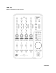
Front panel with controls
3 4
RODEC
f i l t e r t e c h n o l o g y
2
1
21
i n s id e
5
6
RE
20
19
18
22
23
14
17
12
13
8
7
15
9
10
11
16
1)
Input level potentiometer
With this control the input level audio processor can be set.
2)
Over drive LED
When this LED doesn’t light up, the sound is clean (un-distorted). At the moment this
LED lights up the sound becomes distorted. The Restyler contains a soft distortion
system, so even if the sound is slightly distorted, it still sounds comfortable.
3)
Make-up gain potentiometer
With this control the amount of amplification of the output signal of the audio processor
can be set.
4)
0dB LED
This LED lights up at 0dB level of the output signal of the audio processor.
5)
Mix potentiometer
With this knob the proportion between un-processed signal and restyled signal can be
set. When turned completely to the left, only the normal un-processed signal will come
7
at the output. When turned completely to the right only the processed signal will be
audible. This switch works in cooperation with the mix tumbler switch (6).
6)
Mix tumbler switch
This switch turns the audio processor on an off. In the middle position the un–
processed signal will be audible. In the up or down position the mix set with the mix
potentiometer (5) with appear at the output.
Overdrive
LED
0dB
LED
Audio processor
Input
Input
level
Output
level
Mix
potentiometer
Output
Mix
tumbler switch
7)
Master frequency potentiometer
This knob sets the master cut-off frequency at which the built-in filters work.
8)
Slave/trigger frequency potentiometer
This control has two functions; first it defines the operating-frequency of the band-pass
filter which triggers the envelope follower. Secondly it sets, in some situations
depending on the position of the slope-switches (14), the slave cut-off frequency at
which the built-in filters work.
9)
Low pass fader
With this fader the amount of low pass signal can be set.
10)
Band pass fader
With this fader the amount of band pass signal can be set.
11)
High pass fader
With this fader the amount of high pass signal can be set.
12)
Slave frequency guiding LEDs
These LEDs visualize the effective levels with their eventual modulation. These LEDs
also light up when the slave frequency potentiometer (8) is most effective.
In closed fader position the corresponding LED still lights weakly, to indicate what
frequency potentiometer will be significant when the fader is opened.
8
13)
Master frequency guiding LEDs
These LEDs visualize the effective levels with their eventual modulation. These LEDs
also light up when the master frequency potentiometer (7) is most effective.
In closed fader position the corresponding LED still lights weakly, to indicate what
frequency potentiometer will be significant when the fader is opened.
14)
Slope switches
These switches set the slope of the filters and also set the modes in which the audio
processor works.
15)
Slave/trigger frequency indication ring
When this ring lights up totally green, the slave/trigger frequency potentiometer (8)
sets the trigger frequency only. When this ring lights up green and blue, the
slave/trigger frequency potentiometer (8) sets the trigger frequency and the slave filter
frequency.
16)
Master frequency indication ring
When there is no frequency modulation (23) this ring will be blue (static). When the
frequency modulation is activated, the intensity of the LED’s will follow the modulation.
17)
Resonance potentiometer
With this potentiometer it is possible to create a resonance peak at the frequency set
by the master frequency potentiometer (7). By turning this potentiometer more
clockwise the Restyler starts to oscillate at the frequency set by the master frequency
potentiometer (7).
ATTENTION: This oscillation can damage speaker systems or human hearing. So
please be careful by using this control.
18)
Trigger sensitivity
This control sets the input level of the trigger system.
19)
Trigger speed
This control sets the reaction time of the trigger system. When this control is set more
clockwise the trigger acts faster, more counter clockwise the trigger will be delayed.
20)
Trigger transition
Turning this potentiometer more counter clockwise the trigger system will follow the
contours (envelope) of the music signal smoothly. When the potentiometer is turned
more clockwise the transitions between positive and negative trigger signal become
more abrupt because the trigger signal becomes more a square wave.
21)
Trigger indication LED’s
These LEDs display the trigger signal. When the above LED lights up, there is a
positive trigger. When the below LED lights up there is a negative trigger.
22)
Amplitude modulation potentiometers
With these potentiometers in center position there is no amplitude modulation. When
turned clockwise the respective (low pass, band pass or high pass) volume will be
modulated positively (positive trigger signal gives more volume and negative trigger
signal will give less volume). Turned counter clockwise the volumes will be modulated
9
negatively (positive trigger will give less volume and negative trigger will give more
volume).
23)
Frequency modulation potentiometer
With this potentiometer in center position there is no frequency modulation. When
turned clockwise the master filter frequency will be modulated positively (positive
trigger signal will increase the filter frequency and a negative trigger signal will
decrease the filter frequency). Turned counter clockwise the master filter frequency will
be modulated negatively (positive trigger will decrease the frequency and negative
trigger will increase the frequency).
Back panel with connectors
RODEC
RE
f i l t e r t e c h n o l o g y
i n s i d e
PS
E
A
F
E
D
C
B
A)
Power inlet
Inlet to connect the power transformer. Use only the power transformer included with
the Restyler.
B)
Symmetrical input
Symmetrical input, with XLR-JACK combination connector, to connect a synthesizer,
drum-computer, sample-machine, sound-module, guitar, output of a mixing panel, etc..
C)
Asymmetrical analogue input
Input with RCA connectors, to connect the output signal of CD-players, mixing panels,
etc.
D)
Asymmetrical analogue output
Analogue asymmetrical output on RCA connectors, to connect the input of a power
amplifier, a mixing panel, a recording-machine, etc..
10
E)
Symmetrical analogue output
Symmetrical output on JACK connectors, to connect the input of an audio mixing
panel, a power amplifier, an effects-machine, etc..
F)
Symmetrical master output 1 (optional order number 94 002 0028)
Symmetrical output on XLR connectors, to connect the input of an audio mixing panel,
a power amplifier, an effects-machine, etc..
Note: Please use signal cables with a length not exceeding 1 meter for the inputs and the
outputs.
11
Cable configurations
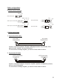
a) Different audio connectors
Sleeve
Tip
RCA (Cinch) male
Pin 2
Sleeve Ring Tip
Pin 1
XLR 3 pole female
JACK 3 pole 1/4 inch male
Sleeve
Pin 3
Tip
Pin 1
JACK 2 pole 1/4 inch male
Pin 2
XLR 3 pole male
Pin 3
b) Different audio cables
1) Asymmetrical RCA cable:
RCA male
Asymmetrical
RCA male
Asymmetrical
Used for connections between: CD-player, MD-player/recorder, Vinyl turntable, DVDplayer/recorder, amplifier, etc and mixing panel.
For connections of analogue signals, you need 2 of these cables for stereo
2) Symmetrical XLR cable:
XLR 3 pole female
Symmetrical
2
1
3
XLR 3 pole male
Symmetrical
1
2
3
Used for connections between: microphone, amplifier, equalizer, loudspeaker-processor,
limiter, etc and mixing panel.
For connections of analogue signals, you need 2 of these cables for stereo
12
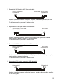
3) Symmetrical XLR female to JACK 3pole male cable:
XLR 3 pole female
Symmetrical
2
JACK 3 pole 1/4 inch male
Symmetrical
1
3
Used for connections between: microphone, amplifier, loudspeaker-processor, etc and
mixing panel.
For stereo connections, you need 2 of these cables
4) Asymmetrical JACK 2 pole male to RCA male cable:
JACK 2 pole 1/4 inch male
Asymmetrical
RCA male
Asymmetrical
Used for connections between: electronic musical instrument, synthesizer, sampler,
effects-machine, amplifier, recorder, etc and mixing panel.
For stereo connections, you need 2 of these cables
5) Symmetrical XLR female to asymmetrical RCA male cable:
XLR 3 pole female
Symmetrical
2
RCA male
Asymmetrical
1
3
Used for connections between: professional CD-player, professional MD-player, sampler,
effects-machine, etc and mixing panel.
For stereo connections, you need 2 of these cables
6) Asymmetrical RCA male to symmetrical XLR male cable:
RCA male
Asymmetrical
XLR 3 pole male
Symmetrical
1
2
3
Used for connections between: professional recorder, sampler, effects-machine, amplifier,
etc and mixing panel.
13
For stereo connections, you need 2 of these cables.
7) JACK 3 pole 1/4 inch male to 2 times JACK 2 pole 1/4 inch male (Y-split) cable:
JACK 3 pole 1/4 inch male
Symmetrical
JACK 2 pole 1/4 inch male
Asymmetrical
JACK 2 pole 1/4 inch male
Asymmetrical
Used for connections between: effects-machine, audio-filter, delay-loop, etc and mixing
panel.
For stereo connections, you need 2 of these cables.
The upper 2 pole JACK is the signal send cable, this has to be connected to the input of
the effects-machine.
The lower 2 pole JACK is the signal return cable, this has to be connected to the output of
the effects-machine.
8) JACK 3 pole 1/4 inch male to 2 times RCA male (Y-split) cable:
JACK 3 pole 1/4 inch male
Symmetrical
RCA male
Asymmetrical
RCA male
Asymmetrical
Used for connections between: effects-machine, audio-filter, delay-loop, etc and mixing
panel.
For stereo connections, you need 2 of these cables
The upper RCA is the signal send cable, this has to be connected to the input of the
effects-machine.
The lower RCA is the signal return cable, this has to be connected to the output of the
effects-machine.
14
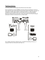
Operating instructions
For correct operation of the Restyler please follow the instructions below.
Ensure all equipment is turned off before connecting anything to the Restyler. Connect an
audio signal to the input of the Restyler and connect the output of the Restyler to the input of a
mixing panel, amplifier, effects machine, computer-soundcard, etc.. When everything is
connected, turn on the different audio units, first all the units and at last the amplifiers.
Because the Restyler has no power-switch, it has to be turned on and off by connecting the
mains power connector to the mains net or by a mains switch.
RODEC
RE
f i l t e r t e c h n o l o g y
i n s i d e
PS
E
LOUDSPEAKER
POWER
AMPLIFIER
CD PLAYER
OR
OR
MIXING PANEL
MIXING PANEL
OUTPUT
DEVICE
LAPTOP
COMPUTER
INPUT
DEVICE
OR
OR
EXTERNAL
SOUNDCARD
SYNTHESIZER
OR
EXTERNAL
SOUNDCARD
LAPTOP
COMPUTER
Due to different experience of Restyler-users, we divided the operating instructions in 3
categories: Basic use, Advanced use and Expert use.
15
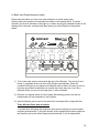
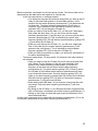
A) Basic use (Single frequency mode)
Please start here when you have never used a Restyler or similar analog units.
Start by placing the actuators in the position as shown on the drawing below. The slope
switches (14) must be activated so they light up. In basic use the grey indicated buttons on the
drawing will not be used, so please keep them during use of the Restyler in the position
shown.
RODEC
f i l t e r t e c h n o l o g y
i n s id e
RE
1) Turn on the audio source connected to the input of the Restyler. Turn the input level
button (1) clockwise till the over drive LED (2) lights up sometimes. When the
overdrive LED lights up, the signal in the Restyler starts to distort. So when you like to
keep the signal clean (undistorted), be sure the input level stays low. If you like a
distorted sound, you can turn the input level (1) more clockwise.
2) Place the mix tumbler switch (6) on the upper (Mix latching) position and the mix
potentiometer (5) fully clockwise on “wet” position.
3) Now the Restyler can be used as low-pass filter, band-pass filter or high-pass filter.
These different filters work as follows:
- Low pass filter: All signals with frequency lower as the frequency set by the master
frequency potentiometer (7) will pass through, all the signals with frequency higher as
the frequency set by the master frequency potentiometer (7) will be suppressed.
16
- Band pass filter: All signals around (bandwidth 1 oktave) the frequency set by the
master frequency potentiometer (7) will pass through, all signals with higher or lower
frequency as the frequency set by the master frequency potentiometer (7) will be
suppressed.
- High pass filter: All signals with frequency higher as the frequency set by the master
frequency potentiometer (7) will pass through, all the signals with frequency lower as
the frequency set by the master frequency potentiometer (7) will be suppressed.
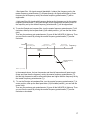
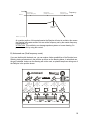
4) To use the Restyler as low pass filter, turn the master frequency potentiometer (7) full
clockwise, slide up the low pass fader (9) till middle position ( you can feel the center
click).
Then turn the make-up gain potentiometer (3) open till the 0dB LED (4) lights up. Then
you can filter the sound by turning the master frequency potentiometer (7) counter
clockwise.
Level
Low frequenc y
(example: Bass guitar)
Cut off
frequency
Mid frequency
(example: Human voice)
High frequency
(example: Cymbals)
Frequency
Maximum
Fader
position
Master frequency
position
Minimum (= no sound)
In the example above, the low frequencies and the mid frequencies will pass trough
(these are lower than the frequency set by the master frequency potentiometer (7))
and the high frequencies will be attenuated (these are higher than the frequency set by
the master frequency potentiometer (7)).
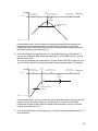
5)
To use the Restyler as bandpass filter, turn the master frequency potentiometer (7) in
center position, slide up the band pass fader (10) till middle position ( you can feel the
center click).
Then turn the make-up gain potentiometer (3) open till the 0dB LED (4) lights up. Then
you can filter the sound by turning the master frequency potentiometer (7) counter
clockwise or clockwise.
17
Level
Cut off
frequency Mid frequency
(example: Human voice)
Low frequenc y
(example: Bass guitar)
High frequency
(example: Cymbals)
Frequency
Maximum
Fader
position
Master frequency
position
Minimum (= no sound)
In the example above, the mid frequencies will pass trough (these are around the
frequency set by the master frequency potentiometer (7)) and the low and high
frequencies will be attenuated (these are lower and higher than the frequency set by
the master frequency potentiometer (7)).
6) To use the Restyler as high pass filter, turn the master frequency potentiometer (7)
fully counter clockwise, slide up the high pass fader (11) till middle position ( you can
feel the center click).
Then turn the make-up gain potentiometer (3) open till the 0dB LED (4) lights up. Then
you can filter the sound by turning the master frequency potentiometer (7) clockwise.
Level
Low frequenc y
(example: Bass guitar)
Cut off
frequency
Mid frequency
(example: Human voice)
High frequency
(example: Cymbals)
Frequency
Maximum
Fader
position
Master frequency
position
Minimum (= no sound)
In the example above, the low frequencies will be attenuated (these are lower than the
frequency set by the master frequency potentiometer (7)) and the mid and high
frequencies will pass trough (these are higher than the frequency set by the master
frequency potentiometer (7)).
7) You can accentuate the cut-off frequency by turning the resonance potentiometer (17)
more clockwise.
18
Level
Low frequency
(example: Bass guitar)
Mid frequency
(example: Human voic e)
High frequency
(example: Cymbals)
Frequency
Maximum
Resonance
position
Minimum (= no sound)
At a certain position of this potentiometer the Restyler will start to oscillate, this means
the Restyler will create sound of his own at the frequency set by the master frequency
potentiometer (7).
ATTENTION: This oscillation can damage speaker systems or human hearing. So
please be careful by using this control.
B) Advanced use (Dual frequency mode)
If you are familiar with the basic use, you can explore further possibilities of the Restyler here.
Start by placing all actuators in the position as shown on the drawing below. In advanced use
the grey indicated buttons on the drawing will not be used, so please keep them during use of
the Restyler in the position shown.
RODEC
f i l t e rt e c h n o l o g y
i n s i d e
RE
19
1) Turn on the audio source connected to the input of the Restyler. Turn the input level
button (1) clockwise till the over drive LED (2) lights up intermittent. When the
overdrive LED lights up, the signal in the Restyler starts to distort. So when you like to
keep the signal clean (undistorted), be sure the input level stays low. If you like a
distorted sound, you can turn the input level (1) more clockwise.
2) Place the mix tumbler switch (6) on the upper (Mix latching) position and the mix
potentiometer (5) fully clockwise on “wet” position.
3) With the 3 slope switches (14) you can create 8 different modes. In some of these
modes both (master (7) and slave (8)) frequency potentiometers will have influence on
the audio signal, in other modes only the master frequency potentiometer (7) will have
influence on the audio signal. By using all of these modes, you can create different
filter patterns with different filter slopes, double bandpass peaks, low or high pass in 2
steps, etc., please check the table below.
20
SLOPE SWITCH
POSITION
LOW PASS
FADER UP
BAND PASS
FADER UP
HIGH PASS
FADER UP
Master
Slave
Master
Slave
Master
Slave
Frequency Frequency Frequency Frequency Frequency Frequency
LP
BP
HP
No influence Influence
LP
BP
BP
Influence No influence Influence
HP
Influence
LP
Influence
Influence No influence Influence No influence Influence
HP
No influence Influence No influence Influence No influence Influence
LP
BP
HP
No influence Influence No influence Influence
LP
BP
Influence
Influence
HP
No influence Influence No influence Influence No influence Influence
LP
BP
HP
No influence Influence No influence Influence No influence Influence
LP
BP
HP
Influence
LP
BP
Influence No influence Influence
Influence
Influence
HP
No influence Influence No influence Influence No influence Influence
21
Below we describe, as example, the first two shown modes. The other modes can be
distracted from the table above and explained in a similar way.
- In the first mode shown, no switches pressed:
• You will have a low pass filter with slow slope when you slide up the LPfader (9) (the ideal fader position is at the middle position). In this
position only the master frequency potentiometer (7) will determine the
cut-frequency. The slave frequency potentiometer (8) will have no
influence. This is indicated by the blue Master frequency influence
indication LED (13) just above the LP-fader (9).
• When you slide up only the BP-fader (10), you will have 2 band-pass
filter peaks with slow slope. One you can move with the master
frequency potentiometer (7) and the other you can move with the slave
frequency potentiometer (8). This is indicated by the green slave
frequency guiding LED (12) and the blue master frequency guiding LED
(13) just above the LP-fader (9).
• When you only slide up the HP-fader (11), you will have a high pass
filter. In this case only the master frequency potentiometer (7) will
determine the cut-frequency. This is indicated by the blue Master
frequency guiding LED (13) just above the LP-fader (9).
• When you slide up more than one fader, you will have a combination of
the above described filters.
- The second mode shown, LP slope switch (14) activated, both other switches
not activated:
• When you slide up only the LP-fader (9) you will have a low pass filter
with 2 steps. The cut frequency of the one step is defined by the
position of the master frequency potentiometer (7) and the cut
frequency of the other step can be set with the slave frequency
potentiometer (8). The green and blue guiding LED (12 and 13) above
the LP-fader (9) will indicate which frequency potentiometer will have
most influence at that moment. So when the green guiding LED (12)
lights up, the slave frequency potentiometer (8) will have most influence
and when the blue guiding LED (13) lights up, the master frequency
potentiometer (7) will have most influence.
• When sliding up the BP-fader (10) you become a band pass filter with
slow slope. Only the master frequency potentiometer (7) will have
influence.
• By sliding up the HP-fader (11), the Restyler becomes a high pass filter
with cut frequency controlled by the master frequency potentiometer (7).
• Sliding up more than one fader will again create a combination of the
above described filters.
In each mode, resonance can be added with the resonance potentiometer (17) on the
cut frequency determined by the master frequency potentiometer (7).
22
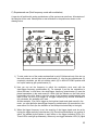
C) Experienced use (Dual frequency mode with modulation)
A user who is familiar with analog synthesizers or filter systems can start here. All actuators of
the Restyler will be used. Please place to start all buttons in the position as shown on the
drawing below.
RODEC
f i l t e rt e c h n o l o g y
i n s i d e
RE
1) To start, select one of the modes as described in point B (Advanced use). Also turn on
the audio source, set the input level potentiometer (1), turn the mix potentiometer (5)
completely clockwise, put the mix tumbler switch (6) on MIX LATCHING position and
turn up the make-up gain potentiometer (3).
2) Now you can set the frequency to which the modulation must react with the
slave/trigger frequency potentiometer (8). For example if you like the modulation to
follow the bass- or kick-drum, the slave/trigger frequency potentiometer (8) must be
placed somewhere in the area around 9 o’clock (the line indicator on the knob points
horizontally to the left). Keep in mind the range of the frequency potentiometers goes
down to 8Hz, so don’t try to trigger on a trigger frequency fully counter clockwise or
fully clockwise, this probably won’t work.
Another example, if you like to trigger on the high-hat (tsssk tsssk tsssk sound) in the
music, you must place the slave/trigger frequency potentiometer (8) somewhere in the
area around 3 o’clock (the line indicator on the knob points horizontally to the right).
3) When the trigger frequency is set, the sensivity of the trigger signal must be set by
turning the trigger sensivity potentiometer (18). Place this potentiometer in a position in
which, the wanted rhythm pattern is well visible on the trigger indication LED’s (21).
These LED’s must light up alternately. When only one trigger indication LED (21) lights
23
up, the trigger sensivity is set too low or too high or the trigger frequency is set to a
frequency which is not present in the used music.
4) Now you can turn one of the amplitude modulation potentiometers (22), clockwise for
positive modulation or counter clockwise for negative modulation. The amplitude of the
associate filter type (LP, BP or HP) will be modulated by the music signal. The
modulation is some kind of automatic sliding up and down the fader (9, 10 or 11)
according to the rhythm of the music. This modulation changes the sound of the music.
To visualize the amplitude modulation, the intensity of the slave frequency guiding
LEDs (12) and master frequency guiding LEDs (13) will follow the modulation pattern
when modulation is activated.
Do not exaggerate with the modulation depth, the best results are obtained with the
modulation depth set around the center position.
5) By turning the frequency modulation potentiometer (23) clockwise or counter
clockwise, the frequency modulation will be activated. This modulation will follow the
trigger pattern set by the slave/trigger frequency potentiometer (8) and trigger sensivity
potentiometer (18). Frequency modulation is some kind of automatic turning the
master frequency potentiometer (7) according to the rhythm of the music. The intensity
of the master frequency indication ring LED’s will also follow the trigger pattern during
frequency modulation. Again, do not exaggerate with the modulation depth, the best
results are obtained with the modulation depth set around the center position.
6) By turning the trigger transition potentiometer (20) counter clockwise, the trigger signal
will become smoother. By turning clockwise the trigger signal will become more
angular. With the trigger speed potentiometer (19) the trigger signal can be delayed.
For example if the modulation of the Restyler is tuned to the bass-drum of the music,
the trigger signal can be delayed by the trigger speed potentiometer, so the trigger
signal will come somewhat later than the bass-drum rhythm.
Both functions, transition and speed, will change the color of the sound.
To keep in mind:
- The working of the RESTYLER depends on the used music. A good effect with certain
settings of the knobs will work perfect on one type of music but will totally destroy the
sound with another piece of music.
- In all user levels a basic rule matters: Practice a lot is the best method to get
experienced with the RESTYLER
24
Options
1) Standard knobs set Restyler
The knobs of a Restyler can be ordered in a set at every authorized RODEC- or
SHERMAN dealer.
Order code: 94 001 0081
2) Symmetrical output
Symmetrical output unit with two 3-pole male XLR-connectors, can be placed in 2 big
holes on the back of the Restyler, without soldering, only a screwdriver needed.
Can be ordered at every authorized RODEC- or SHERMAN dealer.
Order code: 94 002 0028
25
Specifications
0dBm = 0.775V RMS
Input levels:
Output levels:
-
Asymmetrical (RCA): 50mV to 10V / 100kΩ
Symmetrical (JACK): 50mV to 10V / 200kΩ
Symmetrical (XLR): 50mV to 10V / 200kΩ
Asymmetrical (RCA): 0V to 3.3V/ 150Ω
Symmetrical (JACK): 0V to 6.6V / 300Ω
Symmetrical (XLR optional): 0V to 6.6V / 600Ω
Frequency range master and slave frequency potentiometers: 15Hz – 39kHz
Maximum resonance / oscillation level: +15dBm (on asymm. outputs) +21dBm (on symm. outputs)
Crosstalk left to right: >47dB @ 1kHz
Frequency response: +/- 0.50dB from 20Hz to 20kHz
Power supply voltage: 230VAC
Power supply frequency: 50Hz
Power consumption: 18.5W
Operating temperature: 0°C (32°F) – 40°C (104°F)
Operating humidity: 5% - 90% (no condensation)
Mechanical specifications:
Dimensions (W x D x H): 222.0mm (8.74”) x 172.0mm (6.77“) x 115.0mm (4.53“)
Packed box dimensions (W x D x H): 250mm (9.84“) x 250mm (9.84“) x 217mm (8.54“)
Weight (without transfo): 1.90kg (4.19lbs)
Weight (with transfo): 2.60kg (5.73lbs)
Packed weight: 3.10kg (6.83lbs)
26
Explanatory words list
Amplitude: The amplitude is the size or the strength of a vibration. This can be a mechanical vibration,
for example a guitar string or the resulting sound wave or from any other cyclical varying appearance in
time. Because any waveform always varies in size, the value of the wave will also vary. The amplitude
is the value from zero to the maximum hit out or strength of the wave.
AM: Abbreviation of amplitude modulation. With this type of modulation, the amplitude of a signal or the
attenuation of a filter will be modulated by another signal.
Analogue signal: (synonym: analog signal) An analogue signal is any time-continuous signal. The
amplitude of the signal varies continuously in function of time. Human ears can only hear analogue
signals (sounds). Digital sounds must always be converted to analogue signals to make them audible.
Asymmetrical (synonym: unbalanced): An unbalanced line is a transmission line, usually coaxial cable,
whose conductors have unequal impedances with respect to ground.
Bandwidth: The bandwidth of an electronic audio-filter is the difference between the upper and lower
cutoff frequencies.
Band pass filter: This is a type of audio filter. A band pass filter will let all signals within a certain
frequency band pass trough and will attenuate all signals with frequency lower than the lowest cutoff
frequency of the filter and also attenuate all signals with frequency higher than the highest cutoff
frequency of the filter.
Cutoff frequency: In an analog audio filter, the cutoff frequency is the frequency at which the signal is
3dB attenuated comparing to the original (input) signal.
dB: Abbreviation for decibel (1/10 of a Bel). dB is a logarithmic unit of measurement that expresses the
size of a physical quantity relative to a reference level. Its logarithmic nature allows very large or very
small ratios to be represented by a convenient number. The decibel is commonly used in acoustics to
quantify sound levels relative to some 0dB reference. The reference level is typically set at the
threshold of human perception. A reason for using the decibel is that the ear is capable of detecting a
very large range of sound pressures.
DJ: Abbreviation for Disc Jockey. A DJ is a person who plays pre-recorded (not live) music, either or
not in front of an audience.
Dry signal: Opposite of “Wet signal”. This is the signal as it is, without added deformation, effects,
tone-manipulation, etc.
Fader: Is a linear potentiometer. Faders are mostly used to increase or decrease in the level of an
audio signal. By moving the knob, the volume increases or decreases. A fader can be either analogue
whereby a movement of the knob will result in a change of the resistance, or digital where the
movement of the knob generates a binary code used to change the volume.
Filter (audio): An audio filter is an electronic circuit which stops or attenuates certain frequencies or
frequency bands of the audio spectrum. The other frequencies pass trough unattenuated.
FX: Abbreviation for effects-unit. An effects unit is used to manipulate the sound of music or voice.
Some effect units transform the sound completely, others just color the sound picture in a minor way.
27
Frequency: Frequency is the measurement of the number of occurrences of a repeated event per unit
of time. The result is measured in hertz (Hz). A baby can hear tones with frequencies from 20Hz to
20000 Hz (20kHz), but these frequencies become more difficult to hear as people age. When a tone
with a frequency of 20Hz is played by a loudspeaker, the loudspeaker will reciprocate 20 times per
second.
FM: Abbreviation of frequency modulation. With this type of modulation, the frequency of a signal or
cutoff frequency of a filter will be varied by another signal.
High pass filter: This is a type of audio filter. A high pass filter will attenuate all signals with frequency
lower than the cutoff frequency of the filter and let all signal with higher frequency than the cutoff
frequency pass through.
Hz: Abbreviation of Hertz, named after the German physicist Heinrich Rudolf Hertz. The hertz is the unit
of frequency. Its base unit is cycles per second. Each musical note corresponds to a particular
frequency which can be measured in hertz.
I/O: Abbreviation for input / output
Insert: An insert is an access point built into the mixing console, allowing the user to add external line
level devices into the signal flow.
JACK: It is cylindrical in shape, typically with three contacts (TRS), although sometimes with two (a TS
connector) or four (a TRRS connector). TRS stands for Tip, Ring and Sleeve. In audio-systems, it is
used to connect headphones, microphones, effects-units, electrical musical instruments, etc.
kHz: Abbreviation of kilo Hertz, is 1000 Hertz (see Hz)
LED: Abbreviation of Light Emitting Diode. Is an electronic component that emits light when an
electrical current flows through it.
Low pass filter: This is a type of audio filter. A low pass filter will attenuate all signals with frequency
higher than the cutoff frequency of the filter and let all signal with lower frequency than the cutoff
frequency pass through.
Line: Line level is a term used to denote the strength of an audio signal used to transmit analogue
sound information between audio components such as CD-players, DVD-players, input signals of audio
amplifiers, mixing consoles, etc. Sometimes also called AUX (auxiliary) signals.
Modulation: Is the process of varying one waveform in relation to another waveform. The most
common types of modulation are amplitude modulation and frequency modulation.
Modulation depth: This parameter defines how much the signal is modulated by another signal. If the
modulation depth is 0%, there is no modulation, if the modulation depth is 100%, the signal goes on
and off (for amplitude modulation).
Mono: Abbreviation of monaural. Typically there is only one microphone, one loudspeaker, or, in the
case of headphones or multiple loudspeakers, they are fed from a common signal path, and in the case
of multiple microphones, mixed into a single signal path at some stage.
Mute: If an audio signal is muted, it is turned off or it’s volume is turned to a lower level.
Potentiometer: Is an electrical device, which has a user-adjustable resistance. Usually, this is a threeterminal resistor with a sliding contact in the center (the wiper). By moving the wiper, the resistance
changes. These changes are used to to change the characteristics of the audio signal.
28
RCA (cinch, tulip): Is a type of electrical connector that is commonly used in the audio/video market.
The name "RCA" derives from the Radio Corporation of America, which introduced the design by the
early 1940s to allow phonograph players to be connected to amplifiers. Now these connectors are used
for connections between amplifiers, CD-players, phono-turntables, etc. For analogue audio you need 2
of these connectors for a stereo signal. For digital audio (S/P DIF) only one connector is needed for a
stereo signal. The connectors are colour coded: Left or mono -> White, Right -> Red, S/P DIF ->
Orange.
Resonance: In physics, resonance is the tendency of a system to oscillate at larger amplitude at some
frequencies than at others. These are known as the system's resonance frequencies (or resonant
frequencies). At these frequencies, even small periodic driving forces can produce large amplitude
vibrations.
In an electrical (filter) circuit, the resonance is a narrow band of frequencies, around the cutoff
frequency where the signal is amplified.
Sound: Sound can be perceived by the sense of hearing. By sound, we commonly mean the vibrations
that travel through air and are audible to people. Humans and many animals use their ears to hear
sound, but loud sounds and low-frequency sounds can be perceived as vibrations by other parts of the
body via the sense of touch. Sound propagates as waves of alternating pressure, causing local regions
of compression and rarefaction.
Stereo: Stereophonic sound is the reproduction of sound, using two independent audio channels.
Stereophonic sound attempts to create an illusion of location for various instruments within the original
recording.
Subsonic signal: This is an audio signal with frequency below 20Hz. This signal is not audible, it only
creates air movement that can be felt.
Symmetrical (synonym: Balanced): A balanced line or balanced signal pair is a transmission line
consisting of two conductors of the same type, and equal impedance to ground and other circuits.
Balanced lines are operated with differential signals, one of which is the inverse of the other. Balanced
lines reduce the amount of noise per distance, allowing a longer cable run to be practical. This is
because electromagnetic interference will affect both signals the same way. Similarities between the
two signals are automatically removed at the end of the transmission path when one signal is
subtracted from the other.
THD: Abbreviation of Total Harmonic Distortion. When a signal passes through a non-linear device,
additional content is added at the harmonics of the original frequencies. THD is a measurement of the
extent of that distortion.
Volume: The amount of audio level. If the volume increases, the audio level will increase, which results
in a louder sound.
Wave: A wave is a mode of energy transfer from one place to another, often with little or no permanent
displacement of the particles of the medium. Mechanical waves require a medium to transverse the
distance, electromagnetic waves can travel through a vacuum.
Wet signal: Opposite of “Dry signal”. This is the signal inclusive added deformation, effects, tonemanipulation, etc.
XLR: This is a connector invented by Cannon. Originally the "Cannon X" series, subsequent versions
added a Latch ("Cannon XL") and then a Rubber compound surrounding the contacts, which led to the
abbreviation XLR. The most common is the 3-pin XLR3, used almost universally as a symmetrical
audio connector for high quality microphones and connections between equipment.
29
30
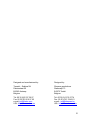
Designed and manufactured by:
Designed by:
Transtel – Sabima NV
Duboisstraat 50
B-2060 Antwerp
Belgium
Sherman productions
Stationwijk 73
B-3272 Testelt
Belgium
Tel: 00 32 (0)3 237 36 07
Fax: 00 32 (0)3 216 97 62
e-mail: [email protected]
URL: http://www.rodec.com
Tel: 00 32 (0)13 78 27 74
Fax: 00 32 (0)13 78 49 21
e-mail : [email protected]
URL: http://www.sherman.be
31