1
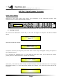
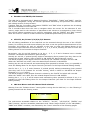
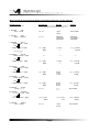
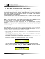
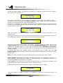
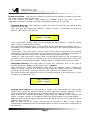
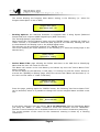
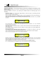
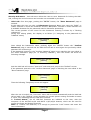
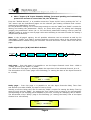
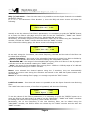
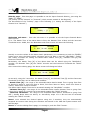
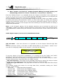
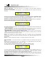
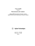
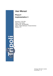
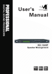
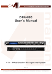
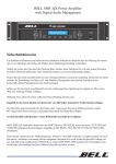
Version 3.0 December.2007
page1
Page2
LMS-2x6 Digital Speaker Processor
Quick User's Manual
Referring to the front panel here below, the description of the LMS-2x6 functions with
reference to the control buttons and encoders.
C3
SERIES
2 x 3 WAY X-OVER
NAV /
PAR 1
A1
ENTER
●
PAR 3
PAR 2
ESC
UTILITY
CLIP
CLIP
CLIP
CLIP
+15dBu
+10dBu
+5dBu
0dBu
-5dBu
+15dBu
+10dBu
+5dBu
0dBu
-5dBu
+15dBu
+10dBu
+5dBu
0dBu
-5dBu
+15dBu
+10dBu
+5dBu
0dBu
-5dBu
A2
1
EDIT
EDIT
ACTIVE
MUTE
2
3
4
5
LMS-2X6
6
Getting Started
As soon as the LMS-2x6 is turned ON, on the LCD will appear in sequence the Device Model
Name
Speaker Management
Class - 3
and the Control Sw Version
Xover 2 x 6
==== Software V0.99C ====
The above screens are temporary ones and after a while they'll disappear leaving the place to
the “Default Screen”.
If no presets are available yet, or if the LMS-2x6 has been reset so to rescue the factory
preset, then the “Default Screen” will be the following
2 x 3 WAY X-OVER
Otherwise, if the LMS-2x6 was running a selected preset, then the “Default Screen” will display
the preset's name, i.e. if the last preset loaded was “Stage1 2x3”, then the screen will be the
following
Stage1
2 x 3
Page3
●
Encoders and ENTER, ESC buttons
The LMS-2x6 is equipped with 3 Relative Encoders, “NAV/PAR1”, “PAR2” and “PAR3”, used for
the “screen navigation” during the several operations allowed by the powerful user interface
and editing section of the processor.
Together with the 3 encoders, the buttons “ENTER” and “ESC” allow to perform the all editing
operations available on the LMS-2x6.
The 3 encoders allow then the user to navigate within the screen for the selection of submenus, pages and for the selection of parameters and values to be assigned to them during
the several editing operations to be used for navigating, and the “ENTER” and “ESC” buttons
allow the euser to confirm or NOT confirm the operations performed by the encoders.
●
UTILITY, A1/A2 and 1/2/3/4/5/6 buttons
The all editing possibilities of the LMS-2x6 can be accessed through the use of the UTILITY
button, for entering the sub-menus allowing the User to set the general charachteristics of the
Processor, the buttons A1 and A1, allowing to the User to enter the Editing Menus of the
Processor's Input Channels and the buttons 1, 2, 3, 4, 5 and 6, allowing the User to enter the
Editing Menus of the Processor's Output Channels.
Particularly, the A1 and A2 buttons so as the 1, 2, 3, 4, 5 and 6 buttons have a double
functions accessible with different “push timings”
Actually A1 and A2, if pushed quickly without maintaining them pressed (but they have to be
pressed for at least 100ms), allow to MUTE or UN-MUTE the Input Channels 1 and 2.
The MUTE condition of the Input Channel is shown by the “ACTIVE” led which will turn ON.
When the “ACTIVE” led is OFF, then the related Input Channel is UN-MUTED.
Pushing the A1 and A2 buttons and maintaining them pressed for almost 2 sec, it is possible to
enter the Editing Menu for the Input Channels (see later for the Input Channel Editing details)
Also for the 1, 2, 3, 4, 5, and 6 buttons, if pushed quickly without maintaining them pressed
(but they have to be pressed for at least 100ms), allow to MUTE or UN-MUTE the Output
Channels 1,2 ,3 ,4 ,5 and 6.
The MUTE condition of the Output Channel is shown by the “MUTE” led which will turn ON.
When the “MUTE” led is OFF, then the related Output Channel is UN-MUTED.
Pushing the 1, 2, 3, 4, 5 and 6 buttons and maintaining them pressed for almost 2 sec, it is
possible to enter the Editing Menu for the Output Channels (see later for the Input Channel
Editing details)
●
LMS-2x6 Menus and Sub-Menus block schemes
Starting from the “Default Screen” coming after turning On the LMS-2x6, i.e. the following if
getting started with the factory preset
2 x 3 WAY X-OVER
The sub-menus accessible thanks to the “UTILITY”, “A1/A2”, “1/2/3/4/5/6”, “ENTER” and
“ESC” buttons, and the accessible parameters and values ranges thanks to the “NAV/PAR1”,
“PAR2” and “PAR3” encoders, are resumed by the “trees” schemes of the following pages:
Page4
MENU “MAIN” [Accessible pushing the “UTILITY” button]
NAV/PAR1 Encoder
[to navigate between menus]
1 MAIN MENU:......
Xover Sub-Menu
ENTER
1.1
1.2
1.3
1.4
>>
ESC
XOVER MENU:......
Load a Xover
>>
XOVER MENU:......
<< Design a Xover >>
XOVER MENU:......
<< Store a Xover
>>
XOVER MENU:......
<< Erase a Xover
>>
2 MAIN MENU:......
<< System Sub-Menu
ENTER
2.1
2.2
PAR2 or PAR3 Encoder
[to chose option, then ENTER to load it;
(*) indicates the not selected option]
ESC
ENTER
ESC
ENTER
ESC
ENTER
Load a Xover
01: Preset 1
:
:
08: Preset 8
Design a Xover
Type: 2x2 WAY XOVER
:
:
Type:
6 WAY XOVER
Store a Xover
01: Preset 1
:
:
01: Preset 8
Erase a Xover
01: Preset 1
:
:
01: Preset 8
>>
SYSTEM MENU:......
<<DelayTime/Distance>>
<<
ENTER
ESC
SYSTEM MENU:......
Initialing Wake-up >>
2.3
ESC
SYSTEM MENU:......
Rotuing Options >>
SYSTEM MENU:......
<< Device Name Title >>
ESC
ENTER
ESC
ENTER
ESC
ENTER
ESC
ENTER
Initialing Wake-up
Wake-up: Mute Hold
Wake-up: Fade-In *
DelayTime/Distance
Display: Time(ms)
Display: Metres *
Rotuing Options
Input Source: Analog
Input Source: Digital
[ENTER] to Editing
Title: Class-3 LMS 2x6
(For Editing the Device's Name, refer to the
Details on the“Utility Menus Use” Section)
3 MAIN MENU:......
<< Interface Sub-Menu >>
ENTER
3.1
ESC
INTERFACE MENU:......
Interface Setup
ESC
ENTER
Remote Interface Setup
Master Source: USB
Master Source:
RS485 *
ESC
ENTER
Remote Id Num =
1
:
32
4 MAIN MENU:......
<< Security Sub-Menu
ENTER
4.1
ESC
SECURITY MENU:......
Unit Lock
ESC
ENTER
Enter Password
[
]
Page5
(For the details about the Password Setting
and Unit Lock, , refer to the “Utility Menus Use”
Section)
MENU “InputA/B” Input Channels Editing [Accessible pushing the “A1/A2” buttons]
NAV/PAR1 Encoder
[to navigate between menus]
NAV/PAR1 Enc.
PAR2 Enc.
PAR3 Enc.
[to chose values for the paramters, no need to confirm the chosen values,
which are automatically loaded during the encoders use]
1. InputA/B
Gain
Gain = + 0.0 dB
PAR1 N.U.
-12 db
:
+12 dB
Same as PAR2
2. InputA/B
Delay =
PAR1 N.U.
000.000mS
[1 mS steps]
2500.979ms
000.000mS
[21 uS steps]
001.000mS
[Freq.] 20Hz
:
20kHz
[Q] 0.05
[Amp.] -15.0 dB
:
+15.0 dB
Delay
0.000 mS
3. InputA/B
PEQ: 1
1.00kHz Q=1.00 + 0.0dB
ENTER
ESC
-> 1.00kHz Q=1.00 + 0.0dB
:
3
[PEQ from 2 to 9]
:::::
12. InputA/B
PEQ: 10
1.00kHz Q=1.00 + 0.0dB
ENTER
:::::
:::::
:::::
ESC
-> 1.00kHz Q=1.00 + 0.0dB
[Freq.] 20Hz
:
20kHz
[Q] 0.05
[Freq.] 20Hz
:
20kHz
Bypass
Lo-1st.
Lo-2nd.
[Freq.] 20Hz
:
20kHz
Bypass
Hi-1st.
Hi-2nd.
PAR1 N.U.
[+]
[ - ]
[Atk time] 5ms
:
200ms
[Rel time] 0.2s
:
2.0s
:
3
[Amp.] -15.0 dB
:
+15.0 dB
13. InputA/B
LoSHF
1.00kHz Bypass + 0.0dB
ENTER
ESC
-> 1.00kHz Bypass + 0.0dB
[Amp.] -12.0 dB
:
+6.0 dB
14. InputA/B
HiSHF
1.00kHz Bypass + 0.0dB
ENTER
ESC
-> 1.00kHz Bypass + 0.0dB
15. InputA/B
Polarity
Polarity = [ + ]
16. InputA/B
A: 5ms
ENTER
-> A:
5ms
[Amp.] -12.0 dB
:
+6.0 dB
Same as PAR2
NoiseGate
R: 0.2s -90dB
ESC
R: 0.2s
-90dB
17. InputA/B
MasterG
Gain = + 0.0 dB
PAR1 N.U.
-12 db
:
+12 dB
Page6
[Amp.] -90.0 dB
:
OFF dB
Same as PAR2
MENU “1/2/3/4/5/6 Output Channels Editing” [Accessible pushing the “1/2/3/4/5/6” buttons]
NAV/PAR1 Encoder
[to navigate between menus]
NAV/PAR1 Enc.
PAR2 Enc.
PAR3 Enc.
[to chose values for the paramters, no need to confirm the chosen values,
which are automatically loaded during the encoders use]
1. Output[x] [Name]
HPF
20.0 Hz
No Cut-Off
PAR1 N.U.
[Freq.] 20Hz
:
20kHz
[Type/Slope] No Cut-Off
:
Chebyshev 24dB/Oct
2. Output[x] [Name]
LPF
20.0 Hz
No Cut-Off
PAR1 N.U.
[Freq.] 20Hz
:
20kHz
[Type/Slope] No Cut-Off
:
Chebyshev 24dB/Oct
[Freq.] 20Hz
:
20kHz
[Q] 0.05
:
3
3. Output[x] [Name] PEQ: 1
1.00kHz Q=1.00 + 0.0dB
ENTER
ESC
-> 1.00kHz Q=1.00 + 0.0dB
[Amp.] -15.0 dB
:
+15.0 dB
[PEQ from 2 to 3]
:::::
6. Output[x] [Name] PEQ: 4
1.00kHz Q=1.00 + 0.0dB
ENTER
:::::
:::::
:::::
ESC
-> 1.00kHz Q=1.00 + 0.0dB
[Freq.] 20Hz
:
20kHz
[Q] 0.05
:
3
[Amp.] -15.0 dB
:
+15.0 dB
[Freq.] 20Hz
:
:
:
20kHz
Bypass
Lo-1st.
Lo-2nd.
Hi-1st.
Hi-2nd.
[Amp.] -12.0 dB
:
:
:
+6.0 dB
PAR1 N.U.
000.000mS
[1 mS steps]
2500.979mS
000.000mS
[21 uS steps]
001.000mS
7. Output[x] [Name] Shelf
1.00kHz Bypass + 0.0dB
ENTER
ESC
-> 1.00kHz Bypass + 0.0dB
8. Output[x] [Name] Delay
Delay =
0.000 mS
9. Output[x] [Name] Limiter
A: 5ms
R: 0.2s +20dB
ENTER
-> A:
5ms
ESC
R: 0.2s
+20dB
[Atk time] 5ms
:
200ms
[Rel time] 0.2s
:
2.0s
[Amp.] -10.0 dB
:
+20.0dB (OFF)
10. Output[x] [Name] Polarity
Polarity = [ + ]
PAR1 N.U.
[+]
[ - ]
Same as PAR2
11. Output[x] [Name] Gain
Gain = + 0.0 dB
PAR1 N.U.
-12 db
:
+12 dB
Same as PAR2
12. Output[x] [Name]
Source = A
PAR1 N.U.
Source
A (ChannelA)
Same as PAR2
B (Channel B)
A+B (Channel A+ Channel B)
13. Output[x] [Name] Name
Name = [Name]
ENTER
-> Name = _
ESC
(For Editing the Device's Name, refer to the Details on the“Utility Menus Use” Section)
Page7
●
Menu “MAIN” [accessed pushing the “UTILITY” button]
From the “Default Screen”, it is possible access the “MAIN” menu pushing the “UTILITY” button
and the Sub-Menus pages can be selected just rotating clockwise and counter-clockwise the
“NAV/PAR1” encoder.
Once selected the sub-menu page, using the “ENTER” button can be accessed the Sub-Menus
pages, again “scrollable” using the “NAV/PAR1” encoder and accessible for the parameters'
editing pushing again the “ENTER' button.
Through the “ESC” button, it is any time possible to go back to the action and page preceding
the “ENTER” button use.
Once inside the Sub-Menus pages, the several options can be scrolled and using the PAR2 or
PAR3 encoders and selected/confirmed pushing the “ENTER” button.
Note: in the all pages' options, the all possible selections appear with an asterisc “*” aside
the option's definition, so to indicate the NOT CURRENTLY RUNNING Options.
The Currently selected and running options HAVE NOT THE ASTERISC aside the option's
definition.
Once a not currently running option, displaied with the asterisc aside, is entered (pushing the
“ENTER” button), then the asterisc will disappear and the shown option will take place as the
currently running one.
Xover Sub-menu – this sub-menu allows to access several operations related to the LMS-2x6
operative mode and to manage the presets storable and recallable with the Unit.
From the “Xover sub-menu”, just pushing the “ENTER” button and then using the “NAV/PAR1”
encoder for sliding the pages, the following pages can be accessed
–
Load a Xover: page allowing the Loading of a preset, of 8 allowed, already stored in the
LMS-2x6 memory.
From this page and rotating the “PAR2” or “PAR3” encoder, it is possible to slide the all
current AVAILABLE presets and their location.
If NO PRESETS are stored yet, the screen will advise that “no presets are available” and
automatically the system will jump back to the “Default” screen.
If Presets are available, then they'll be shown in the “Load a Xover” page
Load a Xover
01: Stage 1 2x6
Using the “PAR2” or “PAR3” encoder it is possible to select the wanted preset to recall.
Pushing furtherly the “ENTER” button, the “[Enter] for Recall.” page will be entered,
showing the selected preset for recalling
[ENTER] for Recall.
01: Stage 1 2x6
Page8
Confirming the preset pushing again the “ENTER” button, will force the LMS-2x6 to load as
current preset the selected one and the following transitory screen will appear
Loading New Xover ......
01: Stage 1 2x6
Once loaded the new preset, the LMS-2x6 will exit the “Load a Xover” page automatically
and the above screen will disappear leaving the place to the “Default” one which will show
the name of the loaded preset and now the current one performed by the LMS-2x6
Stage 1 2x6
Note: any time is possible to quit the recalling action just pushing the “ESC” button.
–
Design a Xover: page allowing to define the operative mode of the LMS-2x6, from a
selection of 5 options.
2x2 WAY XOVER... in this operative mode, the LMS-2x6 is performing a 2 Input to 6
Outputs X-Over, where the 2 Inputs are automatically assigned to the Outputs as follow:
Input A to the Outputs 1/2.
Input B to the Outputs 3/4
the Sum of the 2 Inputs (A+B) to the Outputs 5/6
2x3 WAY XOVER... in this operative mode, the LMS-2x6 is performing a 2 Input to 6
Outputs X-Over, where the 2 Inputs are automatically assigned to the Outputs as follow:
Input A to the Outputs 1/2/3
Input B to the Outputs 4/5/6
4 WAY XOVER... in this operative mode, the LMS-2x6 is performing a 2 Input to 6
Outputs X-Over, where the 2 Inputs are automatically assigned to the Outputs as follow:
Input A to the Outputs 1/2/3/4
Input B or Sum of the 2 Inputs (A+B) to the Outputs 5/6
5 WAY XOVER... in this operative mode, the LMS-2x6 is performing a 2 Input to 6
Outputs X-Over, where the 2 Inputs are automatically assigned to the Outputs as follow:
Input A to the Outputs 1/2/3/4/5
Input B or Sum of the 2 Inputs (A+B) to the Outputs 6
6 WAY XOVER... in this operative mode, the LMS-2x6 is performing a 2 Input to 6
Outputs X-Over, where the 2 Inputs are automatically assigned to the Outputs as follow:
Input A to the Outputs 1/2/3/4/5/6
From this page and rotating the “PAR2” or “PAR3” encoder, it is possible to slide the all
available X-Over oprative modes presets.
The “Design a Xover” page will appear as follow
Design a Xover
Type: 2x3 WAY XOVER
Once selected the desired operative mode for the LMS-2x6, to load it it is enough to push
the “ENTER” button.
Page9
In the case of the following presetted operative modes “2x2 WAY XOVER”, “2x3 WAY
XOVER” and “6 WAY XOVER”, pushing the “ENTER” button to load them, will take to the
following screen, asking for confirming the will to load the selected operative mode
New Xover
[ENTER] to confirm
And if confirmed the will to load the selected operative mode, the LMS-2x6 will be settled
accordingly.
In the case, instead, of the following presetted operative modes “4 WAY XOVER” and “5
WAY XOVER”, pushing the “ENTER” button will be entered a page asking to assign the
Input for the remaining Output channels (the Outputs 5&6, for the “4 WAY XOVER” and the
Output 6 for the “5 WAY XOVER”).
Design a Xover
Output 5&6 Source: A+B
Once assigned the Inputs for the above operative modes, then pushing again the “ENTER”
button the system will go ahead as previously described.
As soon as the operative mode will be loaded, the system will exit automatically the “MAIN
MENU” to jump back to a screen displaying the loaded operative mode.
For the “4 WAY XOVER” operative mode, i.e., the screen will be the following
4 WAY X-OVER + 2
–
Store a Xover: page allowing the Storing of a new preset in the LMS-2x6 memory.
From this page and rotating the “PAR2” or “PAR3” encoder, it is possible to slide the all
current presets, showing the already existent presets' names, or the available empty
(identified by “Empty Program”) locations for new presets.
If No presets are stored yet, the “Store a Xover” page will appear as follow
Store a Xover
01: Empty Program
If we are ready to store an edited configuration of the LMS-2x6, we just need to select the
location we want to use for storing the preset, selecting the location from 8 available
through the “PAR2” or “PAR3” encoder.
Once selected the location (i.e. the location number 1), for editing the Configuration Name
it is necessary to push again the “ENTER” button for entering the “Set Memory Name”
page.
In this page the User can edit an up to 16 Characters Preset's Name just using the
“PAR2” or “PAR3” encoder to chose the character and the “NAV/PAR1” encoder to move
between the 16 available locations for the name's characters positioning.
The current position of the cursor for the characters' entering is shown by a “blinking
underscore”.
Page10
During this editing phase, the display is as follow (i.e. assigning to the preset the “Stage 1
2x6” name to the location 01)
Set Memory Name.
01: Stage 1 2x6
Once chosen the name for the preset, to store it need to push again the “ENTER” button.
The above action will enter the “Enter to Store” page, which will show the selected
location for the preset and the final edited name for it.
If anything is matching our desires, pushing again the “ENTER” button, the preset will be
stored in the selected location with the chosen name and the following transitory screen
will take place on the LCD
Stored to Memory.
01: Stage 1 2x6
Once the preset is stored, the above screen will disappear leaving the place to the
“Default” one.
The “Store a Xover” menu will be exited automatically and if the current loaded preset on
the X-Over was “Stage 1 2x2”, then the screen will be the following
Stage 1
2x2
If during the Preset Storing phase an already occupied location is chosen once in the
“Store a Xover” page, then before to access the “Set Memory Name” page, after having
pushed the “ENTER” button, a further page is entered called “[ENTER] to Overwrite”
asking to confirm the will to Overwrite with the new Preset the one currently stored in the
selected location.
If pushed then again the “ENTER” button, the LMS-2x6 will go ahead with the “Set
Memory Name” page and then with the previously described steps until the preset storing
process end.
Note: any time is possible to quit the storing action just pushing the “ESC” button.
–
Erase a Xover: page allowing to Erase a preset already stored in the LMS-2x6 memory.
From this page and rotating the “PAR2” or “PAR3” encoder, it is possible to slide the all
current AVAILABLE presets and their location.
If NO PRESETS are stored yet, the screen will advise that “no presets are available” and
automatically the system will jump back to the “Default” screen.
If Presets are available, then they'll be shown in the “Erase a Xover” page
Erase a Xover
01: Stage 1 2x6
Using the “PAR2” or “PAR3” encoder it is possible to select the preset that has to be
erased.
Page11
Pushing furtherly the “ENTER” button, the “[Enter] to Erase.” page will be entered,
showing the selected preset will be erased
[ENTER] to Erase.
01: Stage 1 2x6
Confirming the preset pushing again the “ENTER” button, will force the LMS-2x6 to erase
the selected preset and the following transitory screen will appear
Erasing Xover Memory......
01: Stage 1 2x6
Once erased the preset, the LMS-2x6 will exit the “Erase a Xover” page automatically and
the above screen will disappear leaving the place to the “Default”.
Note: any time is possible to quit the recalling action just pushing the “ESC” button.
Page12
System Sub-menu – this sub-menu allows to access several operations related to the LMS2x6 Start Up and General Configuration.
From the “System sub-menu”, just pushing the “ENTER” button and then using the
“NAV/PAR1” encoder for sliding the pages, the following pages can be accessed
–
Initialing Wake-up: page allowing to chose the way of Turning On the LMS-2x6 after
switched the Unit ON.
From this page and rotating the “PAR2” or “PAR3” encoder, it is possible to between to
options: “Mute Hold” and” Fade In”.
Initialing Wake-up
Wake-up: Mute Hold
The currently NOT running option will be displaied wit and “asterisc *” aside the option
name, and the running option without.
After selected the desired option, it can be made active just pushing the “ENTER” button.
In details, the 2 available option are leading the LMS-2x6 to the following behaviour after
turned ON:
MUTE HOLD... when this option is active, after Turning ON the LMS-2x6, the all Outputs,
indepndently from their staus before to turn OFF the Unit, will be MUTED automatically, so
to inhibit the LMS-2x6 to have active Outputs after having been turned ON.
FADE-In... when this option is active, after Turning ON the LMS-2x6, the all Outputs not
previously muted, before to turn OFF the Unit, will be activeted and allowed to “sound” but
the activation is performed through a “Volume Ramp”, avoiding sudden sound to come.
–
DelayTime/Distance: this page allows to select the “Measure's Unit” to be used to
express the Delays: Time (in milliseconds “ms”) or Meters.
Once entered the “DelayTime/Distance” page using the “ENTER” button, rotating the
“PAR2” or “PAR3” encoder, it is possible to select then the Measure's Unit for expressing
the Delay, which will be confirmed entering it just “pushing” the “ENTER” button.
The screen allowing the Measure's Unit for the Delay selection, is the following (i.e. when
the Delay is expressed in “ms”)
DelayTime/Distance
Display: Time(mS)
–
Program Mute Option: this page allows to decide if the “Mute Status” for each output
channel has to be stored together with the all other paramters creating a preset or if it has
to be an independent parameter being everytime ON once turned on the LMS-2x6.
Once entered the “program Mute Option” page using the “ENTER” button, rotating the
“PAR2” or “PAR3” encoder, it is possible to select the desired option for the Mute Status:
OFF: the Mute on the all output channels will be Activated any time on the LMS-2x6 will be
recalled a User's Preset.
ON: the Mute on the all output channels will be Activated or Not on each channel
independently, depending from its last Status before to save as preset the configuration of
the LMS-2x6.
Page13
The screen allowing the Program Mute Option setting, is the following (i.e. when the
Program Mute Option is set on OFF)
Program Mute Option
Mute Status Store: Off
–
Routing Options: the LMS-2x6 Processor is equipped with 2 Anlog Inputs (Balanced
Female XLR) and a stereo S/PDIF Digital Input (RCA connector).
The “Routing Options” page allows
Once entered the “Routing Options” page using the “ENTER” button, rotating the “PAR2” or
“PAR3” encoder, it is possible to select the Main Inputs for the LMS-2x6, allowing the User
to chose between the Analog ones or the S/PDIF Digital ones.
The selection can be confirmed “pushing” the “ENTER” button.
The screen allowing the Input Selection, is the following (i.e. when the Analog Input is the
selected one)
Routing Options
Input Source: Analog
–
Device Name Title: page allowing the Define and Store in the LMS-2x6 an Identifying
Name that the User can chose for the Unit.
This Name will remain in the Unit Memory and shown any time the “Device Name Title”
page is entered.
To set the Name for the LMS-2x6, in this page, it is enough to push the “Enter” button so
to acces the “[ENTER] to Editing” page, where the current Unit's Name will be shown (if i.e.
the Unit's current name is “Class-3 LMS 2x6”)
[ENTER] to Editing
Title: Class-3 LMS 2x6
From this page, pushing again the “ENTER” button, the following “Set Device Name Title”
can be accessed, where it is possible to change the current assigned Name and Edit a new
one..
Set Device Name Title.
Title: _lass-3 LMS 2x6
In the above page the User can edit an up to 16 Characters LMS-2x6 Idenitfying Name
just using the “PAR2” or “PAR3” encoder to chose the character and the “NAV/PAR1”
encoder to move between the 16 available locations for the name's characters positioning.
The current position of the cursor for the characters' entering is shown by a “blinking
underscore”.
Page14
Once chosen the name for the Unit, to store it need to push again the “ENTER” button.
The above action will enter the “Enter to Store” page, which will show the edited
Identifying Name for the LMS-2x6.
If anything is matching our desires, pushing again the “ENTER” button, the Identifying
Name will be stored in the LMS-2x6 Mamory and the following transitory screen will take
place on the LCD
Stored to Memory
Title: Class-3 LMS 2x6
Once the LMS-2x6 Identifying Name is stored, the above screen will disappear leaving the
place to the “Default” one.
Note: any time is possible to quit the storing action just pushing the “ESC” button.
Page15
Interface Sub-menu – this sub-menu allows to access just one Page for the definition of the
Remote Control interface to be used for controlling One or More LMS-2x6 (if working with the
RS485 interface).
From the “Interface sub-menu”, just pushing the “ENTER” button the following page can be
accessed
–
Interface Setup: this “single page” page allows to chose the way of controlling the LMS2x6 by a remote control system.
From this page, pushing the “ENTER” button, can be accessed the futher page allowing to
chose the Physical Layer for the Remote control of the LMS-2x6.
Particularly, the LMS-2x6 can be remotely controlled by an USB interface or by a RS485
interface
Remote Interface Setup
Master Source: USB
If the USB option is selected, then the LMS-2x6 can be controlled 1 to 1 by a Remote
Control System (as the PC).
The USB connection allows the User to control with the Remote Control System ONLY one
LMS-2x6 at time.
If the RS485 option is selected, then the Remote Control System can control MORE LMS2x6 at the same time.
For controlling more LMS-2x6 at the same time, it is necessary to assign to each Unit
connected to the Remote Control Net, and ID number.
Up to 32 LMS-2x6 can be controlled all together by the same Remote Control System.
Once selected the RS485 option for the Remote Interface
Remote Interface Setup
Master Source: RS485
Rotating clockwise the “NAV/PAR1” encoder, the page “Remote ID Num” can be accessed
and in this page just using the “PAR2” or “PAR3” encoder, the ID number for the LMS-2x6
can be assigned, for the Mutli devices Remote Control.
Once assigned the ID number, it has to be confirmed by the “ENTER” button.
If i.e., the ID Number 6 is assigned to the unit, the page will show the following
Remote Interface Setup
Remote ID Num: 6
Page16
Security Sub-menu – this sub-menu allows the User to set a Password for locking the LMS2x6, making the Unit's functions and controls not accessible by the User.
–
Unit Lock: from this page, pushing the “ENTER” button, the “Enter Password” page is
entered.
In this page the User can edit a 6 Characters Password Name just using the “PAR2” or
“PAR3” encoder to chose the character and the “NAV/PAR1” encoder to move between the
6 available locations for the password name's characters positioning.
The current position of the cursor for the characters' entering is shown by a “blinking
underscore”.
During this editing phase, the display is as follow (i.e. assigning to the password the
“LMS2x6” name)
Enter Password
[LMS2x6]
Once edited the Password's name, pushing again the “ENTER” button the “Confirm
Password” page is entered and the LMS-2x6 will ask to write again the previously edited
password for confirming it.
If the password entered in the “Confirm Password” page is not matching the one edited in
the “Enter Password” page (as i.e. Entering “LMS2x0”), then the screen will show the
following message
Confirm Error, Not Set!
[LMS2x0]
And the LMS-2x6 will exit the “Unit Lock” sub-menu and jump to the “Default” screen.
If the password entered in the “Confirm Password” page is matching the one edited in the
“Enter Password” page
Confirm Password
[LMS2x6]
Then the following Temporary screen will appear
Locking Unit
[LMS2x6]
After the unit is locked, the “Unit Lock” menu will be exited automatically and the LMS-2x6
will go back to the “Default” screen showing the current preset running and aside its name
a “Lock” icon indicating that the LMS-2x6 is locked.
In “Locked Status”, the all LMS-2x6 functions are inhibited to the User, with the
exception of the ACTIVE A1/A2 and MUTE 1/2/3/4/5/6 buttons, which can be used for
muting the Input and Output Channels.
Note: to “Unlock” the LMS-2x6, it is enough to press the “Lock” button and enter the
Correct Password.
Page17
●
Menu “Input A/B” Input Channles Editing [accessed pushing and maintaining
pressed for at least 1 second the “A1/A2” buttons]
From the “Default Screen”, it is possible access the “Input A1/A2” menu pushing the “A1” or
“A2” button and the Sub-Menus pages can be selected just rotating clockwise and counterclockwise the “NAV/PAR1” encoder.
For the parameter editing it is on some page enough to use the “PAR2” and “PAR3” encoder for
editing and setting the parameters' values, on some other page, for editing and changing
properly the parameters' values (as i.e. For the filters' parameters setting) need to push the
“ENTER” button in order to enter a page's sub-menu allowing to use each encoder for setting 3
independent parameters.
Note: in the all pages' options, the all possible selections can be selected as said by the
“NAV/PAR1”, “PAR2”, and “PAR3” encoders and the current shown value of the selected option
is AUTOMATICALLY loaded during the encoders' use and stored as current value once left the
page.
Audio Signal Input (A/B) Path Block Scheme
From Input
A/B
G
Delay
10 Band
Param Eq.
Low and High
Shelving Filters
Noise gate
Polarity
MG
To X-Over
and outputs
Gain page – from this page it is possible to set the Input Channels Level from -12db to
+12dB, just using the “PAR1” or “PAR2”.
The value set in this page it is affecting ONLY the input level of the selected Channel, A or B.
The Screenshot of the “Gain” page is the following (i.e. setting the Gain of the Input Channel A
to +0.0dB)
InputA
Gain
Gain = + 0.0dB
Delay page – from this page it is possible to set the Input Channels Delay Time from
000.000mS up to 680.979mS, by steps of 1mS or 21uS.
Actually to set the Delay time can be used the “PAR2” encoder for setting the Delay Time by
steps of 1mS, and the “PAR3”, for setting the “fine” Delay Time by steps of 21 microseconds,
corresponding to the samplng period adopted by the unit, running at a sampling rate of 48kHz.
The Screenshot of the “Delay” page is the following (i.e. setting the Delay Time of the Input
Channel A to 160.187mS)
InputA
Delay
Delay = 160.187mS
Page18
PEQ: [x] sub-menu – from this sub-menu it is possible to set the Input Channels 10 available
Parametric Filters.
If “x” is i.e. The Parametric Filter Number 1, then the PEQ sub-menu screen will show the
following
InputA
PEQ: 1
1.00kHz BW=1.00 + 0.0dB
Actually to set the values of the Filter's parameters, it is necessary to push the “ENTER” button
so to enter the Filter's edit page and to be able to use the “NAV/PAR1”, “PAR2” and “PAR3”
encoders for editing the Filter's Center Freq., Bandwidth BW and Gain.
Particularly, the Center Frequency of the Paramteric Filter can be edited using the “NAV/PAR1”
encoder, the BW the “PAR2” encoder and the Gain the “PAR3” encoder.
Once entered the editing page, the above screen will change as follow
InputA
PEQ: 1
-> 1.00kHz BW=1.00 + 0.0dB
As we said, using the 3 encoders, the Center Fequency, the BW and the Gain of the filter can
be edited and modified.
“Center Frequency”: the range of the selectable frequencies is going from 20Hz to 20kHz by
steps of 1/12 of Octave and can be accessed rotating the “NAV/PAR1” encoder.
“Bandwidth BW”: the range of the selectable BW is going from 0.05 Oct to 3 Oct by steps of
0.05 Oct and can be accessed rotating the “PAR2” encoder.
“Gain”: the range of the selectable Gain is going from -15dB to +15dB by steps of 0.2 dB and
can be accessed rotating the “PAR3” encoder.
Note1: once selected the desired options using the 3 encoders, they are automatically
accepted as current ones during the selection and stored in the LMS-2x6 system status once
left the page.
Note2: to exit the editing filter's page, it is enough to push the “ESC” button.
LoSHF sub-menu – from this sub-menu it is possible to set the Input Channels Low Shelving
Filter.
The LoSHF sub-menu screen, if the filter is bypassed, will show the following
InputA
LoSHF
1.00kHz Bypass + 0.0dB
To set the values of the Filter's parameters, it is necessary to push the “ENTER” button so to
enter the Filter's edit page and to be able to use the “NAV/PAR1”, “PAR2” and “PAR3” encoders
for editing the Filter's Hi Cut Frequency, Filter's Order and Gain.
Particularly, the Hi Cut Frequency of the Low Shelving Filter can be edited using the
“NAV/PAR1” encoder, the Filter's Order can chosen by the “PAR2” encoder and the Gain the
“PAR3” encoder.
Page19
Once entered the editing page, the above screen will change as follow
InputA
LoSHF
-> 1.00kHz Bypass + 0.0dB
As we said, using the 3 encoders, the Hi Cut Frequency, the Order and the Gain of the filter
can be edited and modified.
“Hi Cut Frequency”: the range of the selectable frequencies is going from 20Hz to 20kHz by
steps of 1/12 of Octave and can be accessed rotating the “NAV/PAR1” encoder.
“ Lo Shelving Order”: the selectable Low Shelving Filter's Orders can be selected between
the 1st (Lo-1st.) and the 2nd (Lo-2nd.) one.
It is also possible to Bypass the Low Shelving Filter, selecting the “Bypass” option.
“Gain”: the range of the selectable Gain is going from -15dB to +15dB by steps of 0.2 dB and
can be accessed rotating the “PAR3” encoder.
Note1: once selected the desired options using the 3 encoders, they are automatically
accepted as current ones during the selection and stored in the LMS-2x6 system status once
left the page.
Note2: to exit the editing filter's page, it is enough o push the “ESC” button.
HiSHF sub-menu – from this sub-menu it is possible to set the Input Channels High Shelving
Filter.
The HiSHF sub-menu screen, if the filter is bypassed, will show the following
InputA
HiSHF
1.00kHz Bypass + 0.0dB
To set the values of the Filter's parameters, it is necessary to push the “ENTER” button so to
enter the Filter's edit page and to be able to use the “NAV/PAR1”, “PAR2” and “PAR3” encoders
for editing the Filter's Low Cut Frequency, Filter's Order and Gain.
Particularly, the Low Cut Frequency of the High Shelving Filter can be edited using the
“NAV/PAR1” encoder, the Filter's Order can chosen by the “PAR2” encoder and the Gain the
“PAR3” encoder.
Once entered the editing page, the above screen will change as follow
InputA
HiSHF
-> 1.00kHz Bypass + 0.0dB
As we said, using the 3 encoders, the Low Cut Frequency, the Order and the Gain of the filter
can be edited and modified.
“Low Cut Frequency”: the range of the selectable frequencies is going from 20Hz to 20kHz
by steps of 1/12 of Octave and can be accessed rotating the “NAV/PAR1” encoder.
“High Shelving Order”: the selectable Low Shelving Filter's Orders can be selected between
the 1st (Hi-1st.) and the 2nd (Hi-2nd.) one.
It is also possible to Bypass the High Shelving Filter, selecting the “Bypass” option.
“Gain”: the range of the selectable Gain is going from -15dB to +15dB by steps of 0.2 dB and
can be accessed rotating the “PAR3” encoder.
Note1: once selected the desired options using the 3 encoders, they are automatically
accepted as current ones during the selection and stored in the LMS-2x6 system status once
left the page.
Note2: to exit the editing filter's page, it is enough to push the “ESC” button.
Page20
Polarity page – from this page it is possible to set the Input Channels Polarity, just using the
“PAR1” or “PAR2”.
The polarity can be “Normal” or “Inverted” (which means rotated of 180 Degrees).
The Screenshot of the “Polarity” page is the following (i.e. setting the Polarity of the Input
Channel A to “Normal”)
InputA
Polarity
Polarity = [ + ]
NoiseGate sub-menu – from this sub-menu it is possible to set the Input Channels Noise
Gate Process.
If i.e. The Attack Time of the Noise Gate is 5ms, the Release Time 0.2Sec and the intervent
Threshold set at -90dB, then the NoiseGate sub-menu screen will show the following
InputA
A: 5ms
NoiseGate
R: 0.2s -90.0dB
Actually to set the values of the Noise Gate's parameters, it is necessary to push the “ENTER”
button so to enter the Noise Gate's edit page and to be able to use the “NAV/PAR1”, “PAR2”
and “PAR3” encoders for editing the Noise Gate's Attack Time [A]., Release Time [R] and
Intervent Threshold.
Particularly, the Attack Time [A] of the Noise Gate can be edited using the “NAV/PAR1”
encoder, the Release Time [R] the “PAR2” encoder and the Intervent Threshold the “PAR3”
encoder.
Once entered the editing page, the above screen will change as follow
InputA
-> A: 5ms
NoiseGate
R: 0.2s -90.0dB
As we said, using the 3 encoders, the Attack Time [A], the Release Time [R] and the Intervent
Threshold of the filter can be edited and modified.
“Attack Time [A]”: the range of the selectable Noise Gate's Attack Time is going from 5ms
to 200ms by steps of 1ms from 5ms to 20ms, 5ms from 20ms to 30ms, 10ms from 30ms to
100ms, 20ms from 100ms to 200ms.
The Noise Gate's Attack Time can be accessed rotating the “NAV/PAR1” encoder.
“ Release Time [R]”: the range of the selectable Noise Gate's Release Time is going from
0.2s to 2s by steps of 0.1s and can be accessed rotating the “PAR2” encoder.
“ Intervent Threshold”: The range of the selectable Noise Gate's Threshold is going from
OFF (-100dB; Noise Gate not active) to -90.0dB by steps of 1.0 dB and can be accessed
rotating the “PAR3” encoder.
Note1: once selected the desired options using the 3 encoders, they are automatically
accepted as current ones during the selection and stored in the LMS-2x6 system status once
left the page.
Note2: to exit the editing filter's page, it is enough o push the “ESC” button.
Page21
Master Gain page – from this page it is possible to set the Input Channels Master Level from
-12db to +12dB, just using the “PAR1” or “PAR2”.
The value set in this page it is affecting the input level of both Channels A and B.
The Screenshot of the “Gain” page is the following (i.e. setting the Master Gain +3.0dB)
InputA
MasterG
Gain = + 3.0dB
Page22
●
Menu “Output 1/2/3/4/5/6” Output Channels Editing [accessed pushing and
maintaining pressed for at least 1 second the “1/2/3/4/5/6” buttons]
From the “Default Screen”, it is possible access the “Output 1/2/3/4/5/6” menu pushing the
“1” or “2” or “3” or “4” or “5” or “6” button and the Sub-Menus pages can be selected just
rotating clockwise and counter-clockwise the “NAV/PAR1” encoder.
For the parameter editing, it is on some page enough to use the “PAR2” and “PAR3” encoder
for editing and setting the parameters' values, on some other page, for editing and changing
properly the parameters' values (as i.e. For the filters' parameters setting) need to push the
“ENTER” button in order to enter a page's sub-menu allowing to use each encoder for setting 3
independent parameters.
Note: in the all pages' options, the all possible selections can be selected as said by the
“NAV/PAR1”, “PAR2”, and “PAR3” encoders and the current shown value of the selected option
is AUTOMATICALLY loaded during the encoders' use and stored as current value once left the
page.
Audio Signal Output (1/2/3/4/5/6) Path Block Scheme
From Input
A/B
G
Delay
Low and High
Pass Filters
4 Band Param
Equalizer
Low OR High
Shelving Filt.
Limiter
Polarity
To X-Over
and outputs
HPF sub-menu – from this sub-menu it is possible to set the Output Channels High Pass
Filter.
The HPF sub-menu screen, if the filter is 24dB Linkwitz/Riley on the Output1...named “Low”
(see later for assigning a Name to the outputs..), will show the following
Output1 Low
HPF
20.0 Hz Lnk/Ril 24dB
To set the values of the Filter's parameters, it is enough to use the “PAR2” and “PAR3”
encoders for editing the Filter's Low Cut Frequency and the Filter's Type and Order.
Particularly, the Low Cut Frequency of the High Pass Filter can be edited using the “PAR2”
encoder and the Filter's Type and Order the “PAR3” encoder.
“Low Cut Frequency”: the range of the selectable frequencies is going from 20Hz to 20kHz
by steps of 1/12 of Octave and can be accessed rotating the “PAR2” encoder.
“High Pass Type and Order”: this page allow to select the X-Over's High Pass Filter Shape
and Order.
The available shapes and orders for the High Pass Filter, accessible rotating the “PAR3”
encoder, is listed below:
– NoCut-Off
(High Pass Filter Bypassed)
– Butwrth 6dB
(Butterworth Filter 6dB/Oct Slope)
– Butwrth 12dB
(Butterworth Filter 12dB/Oct Slope)
– Lnk/Ril 12dB
(Linkwitz/Riley Filter 12dB/Oct Slope)
– Bessel 12dB
(Bessel Filter 12dB/Oct Slope)
– Chebysv 12dB
(Chebyshev Filter 12dB/Oct Slope)
Page23
–
–
–
–
–
Butwrth 18dB
Chebysv 18dB
Butwrth 24dB
Lnk/Ril 24dB
Chebysv 24dB
(Butterworth Filter 18dB/Oct Slope)
(Chebyshev Filter 18dB/Oct Slope)
(Butterworth Filter 24dB/Oct Slope)
(Linkwitz/Riley Filter 24dB/Oct Slope)
(Chebyshev Filter 24dB/Oct Slope)
Note1: once selected the desired options using the 2 encoders, they are automatically
accepted as current ones during the selection and stored in the LMS-2x6 system status once
left the page.
Note2: to exit the editing filter's page, it is enough to push the “ESC” button.
LPF sub-menu – from this sub-menu it is possible to set the Output Channels Low Pass Filter.
The LPF sub-menu screen, if the filter is 24dB Linkwitz/Riley on the Output1...named “Low”
(see later for assigning a Name to the outputs..), will show the following
Output1 Low
LPF
20.0 Hz Lnk/Ril 24dB
To set the values of the Filter's parameters, it is enough to use the “PAR2” and “PAR3”
encoders for editing the Filter's High Cut Frequency and the Filter's Type and Order.
Particularly, the High Cut Frequency of the Low Pass Filter can be edited using the “PAR2”
encoder and the Filter's Type and Order the “PAR3” encoder.
“High Cut Frequency”: the range of the selectable frequencies is going from 20Hz to 20kHz
by steps of 1/12 of Octave and can be accessed rotating the “PAR2” encoder.
“Low Pass Type and Order”: this page allow to select the X-Over's Low Pass Filter Shape
and Order.
The available shapes and orders for the Low Pass Filter, accessible rotating the “PAR3”
encoder, is listed below:
– NoCut-Off
(Low Pass Filter Bypassed)
– Butwrth 6dB
(Butterworth Filter 6dB/Oct Slope)
– Butwrth 12dB
(Butterworth Filter 12dB/Oct Slope)
– Lnk/Ril 12dB
(Linkwitz/Riley Filter 12dB/Oct Slope)
– Bessel 12dB
(Bessel Filter 12dB/Oct Slope)
– Chebysv 12dB
(Chebyshev Filter 12dB/Oct Slope)
– Butwrth 18dB
(Butterworth Filter 18dB/Oct Slope)
– Chebysv 18dB
(Chebyshev Filter 18dB/Oct Slope)
– Butwrth 24dB
(Butterworth Filter 24dB/Oct Slope)
– Lnk/Ril 24dB
(Linkwitz/Riley Filter 24dB/Oct Slope)
– Chebysv 24dB
(Chebyshev Filter 24dB/Oct Slope)
Note1: once selected the desired options using the 2 encoders, they are automatically
accepted as current ones during the selection and stored in the LMS-2x6 system status once
left the page.
Note2: to exit the editing filter's page, it is enough to push the “ESC” button.
Page24
PEQ: [x] sub-menu – from this sub-menu it is possible to set the Output Channels 4
available Parametric Filters.
If “x” is i.e. The Parametric Filter Number 1, then the PEQ sub-menu screen will show the
following
Output1 Low
PEQ: 1
1.00kHz BW=1.00 + 0.0dB
Actually to set the values of the Filter's parameters, it is necessary to push the “ENTER” button
so to enter the Filter's edit page and to be able to use the “NAV/PAR1”, “PAR2” and “PAR3”
encoders for editing the Filter's Center Freq., Bandwidth BW and Gain.
Particularly, the Center Frequency of the Paramteric Filter can be edited using the “NAV/PAR1”
encoder, the BW the “PAR2” encoder and the Gain the “PAR3” encoder.
Once entered the editing page, the above screen will change as follow
Output1 Low
PEQ: 1
-> 1.00kHz BW=1.00 + 0.0dB
As we said, using the 3 encoders, the Center Fequency, the BW and the Gain of the filter can
be edited and modified.
“Center Frequency”: the range of the selectable frequencies is going from 20Hz to 20kHz by
steps of 1/12 of Octave and can be accessed rotating the “NAV/PAR1” encoder.
“Bandwidth BW”: the range of the selectable BW is going from 0.05 Oct to 3 Oct by steps of
0.05 Oct and can be accessed rotating the “PAR2” encoder.
“Gain”: the range of the selectable Gain is going from -15dB to +15dB by steps of 0.2 dB and
can be accessed rotating the “PAR3” encoder.
Note1: once selected the desired options using the 3 encoders, they are automatically
accepted as current ones during the selection and stored in the LMS-2x6 system status once
left the page.
Note2: to exit the editing filter's page, it is enough to push the “ESC” button.
Shelf sub-menu – from this sub-menu it is possible to select the Shelving Filter type and
Order.
The selectable Shelving filters are Lo (Low Shelving) or Hi (High Shelving) and the Filters'
order can be selected between the 1st and the 2nd one.
It is also possible to Bypass the Shelving filter, selecting the “Bypass” option.
The LoSHF sub-menu screen, if the filter is bypassed, will show the following
Output1 Low
Shelf
1.00kHz Bypass + 0.0dB
To set the values of the Filter's parameters, it is necessary to push the “ENTER” button so to
enter the Filter's edit page and to be able to use the “NAV/PAR1”, “PAR2” and “PAR3” encoders
for editing the Filter's Cut Frequency, Filter's Type and Order and Gain.
Particularly, the Cut Frequency of the Selected Shelving Filter can be edited using the
“NAV/PAR1” encoder, the Filter's Type and Order can chosen by the “PAR2” encoder and the
Gain the “PAR3” encoder.
Page25
Once entered the editing page, the above screen will change as follow
Output1 Low
Shelf
-> 1.00kHz Bypass + 0.0dB
As we said, using the 3 encoders, the Cut Frequency, the Type and Order and the Gain of the
filter can be edited and modified.
“ Cut Frequency”: the range of the selectable frequencies is going from 20Hz to 20kHz by
steps of 1/12 of Octave and can be accessed rotating the “NAV/PAR1” encoder.
“Shelving Type Order”: the selectable Shelving Filter's Type can be selected betweenn Low
and High Shelving, and the Orders can be selected between the 1 st (Lo/Hi-1st.) and the 2nd
(Lo/Hi-2nd.) one.
It is also possible to Bypass the Shelving Filter, selecting the “Bypass” option.
“Gain”: the range of the selectable Gain is going from -15dB to +15dB by steps of 0.2 dB and
can be accessed rotating the “PAR3” encoder.
Note1: once selected the desired options using the 3 encoders, they are automatically
accepted as current ones during the selection and stored in the LMS-2x6 system status once
left the page.
Note2: to exit the editing filter's page, it is enough to push the “ESC” button.
Delay page – from this page it is possible to set the Output Channels Delay Time from
000.000mS up to 680.979mS, by steps o 1mS or 21uS.
Actually to set the Delay time can be used the “PAR2” encoder for setting the Delay Time by
steps of 1mS, and the “PAR3”, for setting the “fine” Delay Time by steps of 21 microseconds,
corresponding to the samplng period adopted by the unit, running at a sampling rate of 48kHz.
The Screenshot of the “Delay” page is the following (i.e. setting the Delay Time of the Output
Channel 1 to 160.187mS)
Output1 Low
Delay
Delay = 160.187mS
Limiter sub-menu – from this sub-menu it is possible to set the Output Channels Limiter.
If i.e. The Attack Time of the Limiter is 5ms, the Release Time 0.2Sec and the Intervent
Threshold set at +5dB, then the Limiter sub-menu screen will show the following
Output1 Low
Limiter
A: 5ms R: 0.2s +5.0dB
Actually to set the values of the Limiter's parameters, it is necessary to push the “ENTER”
button so to enter the Limiter's edit page and to be able to use the “NAV/PAR1”, “PAR2” and
“PAR3” encoders for editing the Limiter's Attack Time [A]., Release Time [R] and Intervent
Threshold.
Particularly, the Attack Time [A] of the Limiter can be edited using the “NAV/PAR1” encoder,
the Release Time [R] the “PAR2” encoder and the Intervent Threshold the “PAR3” encoder.
Page26
Once entered the editing page, the above screen will change as follow
Output1 Low
Limiter
-> A: 5ms R: 0.2s +5.0dB
As we said, using the 3 encoders, the Attack Time [A], the Release Time [R] and the Intervent
Threshold of the filter can be edited and modified.
“ Attack Time [A]”: the range of the selectable Limiter's Attack Time is going from 5ms to
200ms by steps of 1ms from 5ms to 20ms, 5ms from 20ms to 30ms, 10ms from 30ms to
100ms, 20ms from 100ms to 200ms.
The Limiter's Attack Time can be accessed rotating the “NAV/PAR1” encoder.
“Release Time [R]”: the range of the selectable Limiter's Release Time is going from 0.2s to
2s by steps of 0.1s and can be accessed rotating the “PAR2” encoder.
“Intervent Threshold”: the range of the selectable Limiter's Threshold is going from +20dB
(Limiter not active) to -10.0dB by steps of 0.5 dB and can be accessed rotating the “PAR3”
encoder.
Note1: once selected the desired options using the 3 encoders, they are automatically
accepted as current ones during the selection and stored in the LMS-2x6 system status once
left the page.
Note2: to exit the editing filter's page, it is enough to push the “ESC” button.
Polarity page – from this page it is possible to set the Output Channels Polarity, just using
the “PAR1” or “PAR2”.
The polarity can be “Normal” or “Inverted” (which means rotated of 180 Degrees).
The Screenshot of the “Polarity” page is the following (i.e. setting the Polarity of the Output
Channel 1 to “Normal”)
Output1 Low
Polarity
Polarity = [ + ]
Gain page – from this page it is possible to set the Output Channels Level from -12db to
+12dB, just using the “PAR1” or “PAR2”.
The value set in this page it is affecting ONLY the Output level of the selected Channel,
1/2/3/4/5 or 6.
The Screenshot of the “Gain” page is the following (i.e. setting the Gain of the Output Channel
1 to +0.0dB)
Output1 Low
Gain
Gain = + 0.0dB
Page27
Source page – from this page it is possible to assign the Input for the edited Output Channel.
Particularly, to any Output Channel can be assigned one of the following Inputs:
1. Input A
2. Input B
3. Sum of Input A + Input B
The Screenshot of the “Source” page is the following (i.e. Assigning to the Output Channel 1
the Input A)
Output1 Low
Source
Source = A
The Input for the edited Output channel can be selected rotating either “PAR2” or “PAR3”.
Name page – from this page it is possible to assign a NAME to the edited Output Channel.
To Edit and assign a 6 Charachters Name to the edited Output Channel, it is necessary from
the Name Page to push the “ENTER” button so to access the Name editing phase.
The Screenshot of the “Name” page is the following (i.e. When the name is “Low” for the
Output Channel 1 )
Output1 Low
Name = Low
Name
To Edit a new Name, push “ENTER” button and the following page will appear
Output1 Low
->
Name = _Low
Name
Where the “underscore” will be blinking.
Now, just select the Charcter position from 6 available, sliding between them using the
“NAV/PAR1” encoder, then using the “PAR2” or 'PAR3” encoder, it is possible to select the
desired character for Editing the desired Name.
Once defined the new Name, i.e. “Sub”, push the “ENTER” button for confirming the edited
Name....an the new name will take the place of the old one on the screen
Output1 Sub
Name = Sub
Page28
Name
●
LMS-2x6 Technical Specifications
The LMS-2x6 Digital Speaker Processor is based on a powerful analog and digital 4xDSP
platforms having the following specifications
Analog Input Signal:
Maximum Input Level:
Analog Output Signal:
Maximum Output Level:
ChA/ChB,
+20dBu
Ch1/Ch2/Ch3/Ch4/Ch5/Ch6
+20dBu
Digital Processing (DSP):
A/D Converters:
D/A Converters:
Sampling Frequency:
S/PDIF Stereo Digital Input:
4xTMS57002, 24bits (data) x 32 bits (coeff.)
AKM5383, 24bits
AKM4393, 24bits
48kHz
32kHz, 44.1kHz and 48kHz Sources Accepted
S/N:
THD+N:
Frequency Response (Bypass):
106dBA; 115dBA [With Noise Gate Active]
0.005%
20Hz – 20kHz (+- 1 dB)
Power Supply:
Remote Control:
Switching Power Supply
USB, RS485 [For Multiprocessors Net]
Page29
Bal. Female XLR
Bal. Male XLR