1
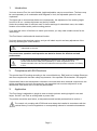
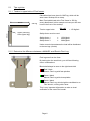
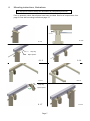
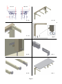
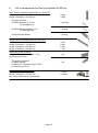
FlexiElectric 30-66XXX-3 User Manual Mounting Instructions Keep this folder with product at all times! PDF 6087 / 01.09.2014 PA 2004 00634 Contents 1. INTRODUCTION ................................................................................................................................................. 3 2. COMPLIANCE WITH EU-DIRECTIVES ........................................................................................................ 3 3. APPLICATION ..................................................................................................................................................... 3 4. TECHNICAL DATA FLEXI ............................................................................................................................... 4 5. SUPPLY POINTS, WATER SUPPLY AND WASTE ....................................................................................... 5 5.1 Tips og tricks ................................................................................................................................................. 6 5.1.1 Tension in upper bolts of Flexi frames .......................................................................................................... 6 5.1.2 Determine the difference between a MANUEL and Electric Flexi Leg. ....................................................... 6 6. MOUNTING INSTRUCTIONS, ILLUSTRATIONS ........................................................................................ 7 6. MOUNTING INSTRUCTIONS, DESCRIPTIONS ......................................................................................... 12 6.1 6.2 6.3 6.4 6.5 6.6 6.7 6.8 6.9 6.10 6.11 6.12 6.13 6.14 6.15 6.16 Assembly of frame ....................................................................................................................................... 13 Mounting the frame on the wall .................................................................................................................. 14 Mounting of fittings for front fascia ............................................................................................................ 14 Mounting the worktop ................................................................................................................................. 14 Mounting the wooden front fascia .............................................................................................................. 14 Mounting the side fascia ............................................................................................................................. 14 Adjusting the worktop/ support arms .......................................................................................................... 15 Mounting the control unit ........................................................................................................................... 15 Mounting the operating unit ....................................................................................................................... 15 Mounting the safety strip under the worktop .............................................................................................. 16 Mounting the flexible water connections and waste hoses.......................................................................... 16 Mounting the supporting feet ...................................................................................................................... 16 Mounting the covers for the legs ................................................................................................................. 16 Mounting the press pad for disabled persons ............................................................................................. 17 Mounting of distance plates (1cm) for skirting board ................................................................................. 17 Mounting the concealment panels............................................................................................................... 17 7. PERFORMANCE TEST .................................................................................................................................... 18 8. LIST OF COMPONENTS FOR FLEXI FOR WORKTOP 60-300 CM ........................................................ 19 8. LIST OF COMPONENTS FOR FLEXI FOR WORKTOP 60-300 CM ........................................................ 20 9. OPTIONS FOR FLEXI ...................................................................................................................................... 21 10. SAFETY IN USE ................................................................................................................................................. 23 11 CLEANING AND MAINTENANCE ................................................................................................................ 24 11.1 Cleaning ...................................................................................................................................................... 24 11.2 Maintenance................................................................................................................................................ 24 11.3 Service schedule, operation and maintenance ............................................................................................ 25 12. TROUBLE SHOOTING ..................................................................................................................................... 25 13. CE-MARKING ......................................................................................................................................................... 26 14. FLEXI ELECTRIC QUICKSTART GUIDE ................................................................................................... 27 14. COMPLAINTS .................................................................................................................................................... 28 Page 2 1. Introduction You have chosen Flexi, the multi-flexible, height-adjustable, easy-to-mount frame. The frame may be used separately or in combination with Diagonal or Verti, the adjustable system for wall cupboards. The frame has no inconvenient fascia and, consequently, the adjustment of the working height from 65 to 95 cm + worktop thickness may be fully utilised. Under the worktop there is sufficient room for knees and legs for wheelchair users, who obtain freedom of movement and a perfect working posture. If you want the colour of the frame to match your kitchen, you may order suitable covers for the vertical legs. The Flexi frame is delivered with electrical function. You have chosen the electrical version, and you will obtain a quick and easy adjustment of the frame by activating the control buttons. This document must ALWAYS be kept with the product and have been read and understood by the user. The correct use, operation and inspection are decisive factors for efficient and safe performance. If this product is electrically adjustable in height there is a risk of squeezing. The product must therefore always be operated by or under the guidance of an experienced adult, who has read and understood the importance of section 10 ”Safety in use”. 2. Compliance with EU-Directives This product has CE-marking according to the current Machinery, EMC and Low Voltage Directives and thus complies with the basic safety requirements. See separate CE-declaration. See page 26. If these table frames are assembled or otherwise connected with other electrical components, this will be considered a new unit. Consequently, the assembled unit must be subjected to a risk assessment, after which the CE mark may be awarded. 3. Application The Flexi frame is adjustable in height in order to obtain optimum working height for user and helper. Do NOT use Flexi as a lifting table or person lifter. The product should be used indoor, at temperatures and humidity as described in section 4 The control unit complies with IP32/ll and must always be installed in accordance with the national Heavy Current Regulations or corresponding national or international standards. Page 3 4. Technical data Flexi Product name: Flexi Length of worktop = 60-300 cm (205-300 cm supported by three legs) Item numbers: Electrical 30-66XXX: XXX = Length of worktop The frame is always 5 cm shorter than the worktop Height adjustment: 65–95 cm without worktop Material: Welded steel tubes St. 37 Aluminium alloy 606045-T6 Stainless steel spindle and various plastic components Surface treatment: Chromite, Powder coating, Standard RAL 9010, mat white Max. load of frame: 150 kg evenly distributed over the entire worktop Power supply: 230VAC / 2.5A / 50 Hz - Alternatively 100VAC / 50/60 Hz Standby primary: ≤0,3W Control voltage: 24VDC Duty circle: Max. 10 % conform to 1 min. active / 9 min. pause Speed: Approx. 32 mm/sec Lifting time stroke 30 cm: Approx. 10 sec. Temperature: 5-45°C Air humidity: 5-85% (non-condensing) Complaints: See complaints, page 28. Manufacturer: Ropox A/S, DK-4700 Naestved, Tel.: +45 55 75 05 00 Page 4 5. Supply points, water supply and waste 8 14 Length of the worktop længde Length of Aluminum profile = Length of worktop minus 5 cm Length of Hexagon shaft = Length of worktop minus 15 cm It is advisable to place water supply and waste within the hatched area. Also it is important to use flexible hoses for water supply and waste to ensure that the Flexi will move freely without obstacles within the height adjustment range 65-95 cm. excl. worktop. It is advisable to place the water supply and waste close to the sink. The drain may also be installed in the floor. Arrange for the fixed feed pipes on the wall to be pointing down, at a height of max. 30 cm. This will ensure that the flexible feed pipes will always flex in a neat curve close to the wall without kinking. A 90 degree valve with a 1/2" exposed thread is recommended. The control unit complies with IP32/ll and must always be installed in accordance with the national Heavy Current Regulations or corresponding international or national standards. The cables to the control unit must be able to move freely during height adjustment of the Flexi. For worktops with cut-outs the distance from either side of the worktop should be considered as shown on the illustration. 10 cm 10 cm Page 5 Always keep 0,5 cm space all away around the worktop 5.1 Tips og tricks 5.1.1 Tension in upper bolts of Flexi frames Calculation has been done for ONE leg, which will be worst case. Worktop 62 cm deep. 62 cm 150 Kg Max. Permissible load at the Flexi frame is 150 Kg, evenly distributed. In this example we have put the max. Load in the front of the worktop. 150 x 62 35 x 2 35 cm Tension upper bolts: Upper mounting holes (2pcs./leg) = 133 Kg/bolt Safety factor must be used: Safety factor 1 Safety factor 2 Safety factor 3 133 Kg/bolt 266 Kg/bolt 399 Kg/bolt Under normal circumstances the load will be distributed to the two legs (4 bolts) 5.1.2 Determine the difference between a MANUEL and Electric Flexi Leg. Flexi leg seen from the front: By looking thru the small hole, you will face following colour combinations: Black shall always be seen to the right hand side! Red / black Electric Flexi Leg with fast spindles Green / black Manuel Flexi Leg with slow spindles Green / black Manuel Flexi Leg, which might be retrofitted to an Flexi electric, running with a slow. This is very important information to make a visual verification of the exact Flexi model. Page 6 6. Mounting instructions, illustrations The equipment should always be assembled by competent personnel. Prior to assembly check that all parts have been provided. See list of components, from page19. See also mounting instructions page 13. 2,5 cm 6.1.1 6.1.2 Stop ring Nylon Spacer 6.1.3 6.1.4 6.1.5 6.1.6 Stop ring Nylon spacer 6.1.7 6.1.8 Page 7 21,5 cm 18,5 cm 6.1.9 6.1.10 6.1.11 6.2.2 6.3.1 6.3.2 6.4.1 Page 8 2,5 cm 6.4.2 6.4.3 6.5.1 6.5.2 6.6.1 6.7.1 6.7.2 6.8.1 Page 9 Connections to Control box 6.8.2 Power Cable Motor Cable M2 Split Cable for safety stop Motor Cable M1 S2 Cable for Control switch Safety strip (option) 6.8.3 . 6.9.1 Option: Safety strip Location of drain 6.10.1 6.11.1 Page 10 Mounting of accessories 6.12.1 6.12.2 6.13.1 6.13.2 6.14.1 6.14.3 Page 11 6.14.2 6.15.1 45 cm L= Worktop length 6.16.1 6.16.2 L= Worktop length 40 cm Lower consealment panel Lower consealment panel in case of supporting feet 8 cm 6.16.3 Distance between feet 3 cm 40 cm L= Worktop length 8 cm 6.16.4 Page 12 6. Mounting instructions, descriptions The equipment should always be assembled by competent personnel. Prior to assembly check that all parts have been provided. See list of components, from page 19. See also mounting drawings page 7. 6.1 Assembly of frame 6.1.1 Push the left leg into the groove of the lower side of the aluminium profile. 6.1.2 Position the adjustable legs on the aluminium profile, 2,5 cm from the left edge. If there are any socket outlets obstructing the legs, move the leg a little towards the middle. For frames with two legs, place one leg on either side. For frames with three legs, place the third leg at the middle of the aluminium profile. Secure each leg to the aluminium profile with two bolts. 6.1.3 Push the connecting spindle through the leg on the left side. Push the washer and stop ring onto the connecting spindle so that the washer faces the leg. 6.1.4 Push the motor with fittings onto the spindle. If the motor is not parallel with the leg then turn the motor to vertical position, see 6.1.7 6.1.5 All support arms, but 2, may be pushed into the aluminium profile from the right hand side to the required position and fastened with two screws on each support. We recommend a maximum distance between the support arms of 60 cm in order to obtain optimum stability. 6.1.6 The left hand side support arm may be pushed into the profile, positioned direct on top of the left leg and fasten it. 6.1.7 For worktop length 105-300 cm an additional motor must be mounted as described. Place the washer and stop ring between the motor and the right-hand leg so that the washer faces the leg. 6.1.8 Push the right-hand leg into the groove of the bottom side of the aluminium profile and fasten it in a distance of 2,5 cm from the edge of the aluminium. 6.1.9 Place the motors at the illustrated distance from either end of the aluminium profile and fasten them. 6.1.10 The right hand side support arm may be pushed into the profile, positioned direct on top of the left leg and fasten it. 6.1.11 Move the stop rings and washers on the spindle to both sides, so that the washer always faces the leg. Secure it by fastening of stoprings. Where you have an adjustable leg always position a support arm directly over it. Do not adjust the tilting of the arm supports that are positioned on top of the legs (see 6.7). If the sink or hotplate is placed at the middle of the worktop, move the third leg if any, to the right or left to ensure that the leg and support arm are fitted in the immediate vicinity of the sink, hotplate etc. Page 13 6.2 Mounting the frame on the wall 6.2.1 Place the frame against the wall and align it. Adjust the two threaded bolts under the legs to ensure that the frame is horizontal. To obtain the correct height (65-95 cm without worktop) adjust the threaded bolt to each leg. After mounting, turn the threaded bolts up so they are hidden by the leg. Mark and drill the holes for fastening. Fasten the frame to the wall by means of screws and raw plugs suiting the material of the wall. 6.2.2 Misalignments up to 0,45 cm on the wall may be adjusted by fitting the provided spacers (0,15 cm) between the legs and the wall. Loosen the legs a bit and slide the spacers in between the wall and the legs, as required, at the top or bottom depending on whether the wall is vertical. 6.3 Mounting of fittings for front fascia 6.3.1 Fittings for mounting of the wooden front fascia are provided, corresponding to the number of support arms. Place the front fascia fittings on the side of the support arm and fasten them loosely by means of the screw provided. 6.3.2 On the outermost support arms we recommend pointing the front fascia fittings towards the middle of the frame to prevent them from conflicting with the side fascia. 6.4 6.4.1 Mounting the worktop Place the tabletop on the frame. The maximum permissible distance from the back of the tabletop to the wall is 0.5 cm. (safety issue) If the frame is moved away from the wall, the distance from the back of tabletop to the wall MUST still be equal to or less than 0.5 cm. 6.4.2 The standard aluminium profile is 5 cm shorter than the worktop, resulting in a 2.5 cm projection on either side. 6.4.3 Fasten the worktop with screws through the holes of the support arms. 6.5 Mounting the wooden front fascia 6.5.1 Fasten the wooden front fascia at the required position under the worktop by means of a clamp. Press the front fascia fittings forward against the wooden front fascia and fasten with screws from the inside. 6.5.2 By screwing the front fascia fittings into the worktop you pull the front fascia upward. Finally tighten the screws on the side of the support arm. 6.6 Mounting the side fascia Page 14 6.6.1 Furniture fittings are provided with the frame to keep the wooden side fascia up against the worktop. 6.7 Adjusting the worktop/ support arms 6.7.1 After placing the worktop on the frame you may have to compensate for the weight of the worktop if the frame is no longer horizontal from the wall to the front fascia. 6.7.2 By means of the two lower screws of each support arm the ”tilting” may be adjusted. Start by loosening the two screws fastening the support arm to the aluminium profile and adjust the two lower screws to make the worktop horizontal. Finally retighten the two upper screws. Repeat this procedure for the support arms in the middle. Do not adjust the support arms placed directly above the legs. 6.8 Mounting the control unit Warning ALWAYS switch off mains voltage during assembly Check national regulations to determine the correct location of the control unit. 6.8.1 The 2 special nuts on the control box plate are turned vertically, making them fit into the long track in the alu profile. The plate is positioned on the front of the alu profile and the 2 M6 screws are tightened. (The special nuts are automatically turned in place, when the screws are tightened) 6.8.2 Mount all cable connections as illustrated. Note that the safty strip sit in S2. For connection sequence see section 7 (start-up procedure) on page 18 6.8.3 Place the loose cables in the cable bearers and fit the bearers in the grooves of the aluminium profile. 6.9 Mounting the operating unit 6.9.1 The control switch for the height adjustment must be fitted in the wooden front fascia. It consists of a control switch with a 1,5 m long cable provided with a DIN plug for the control switch. Choose the required position in the front fascia and drill an 18 mm dia. hole in the fascia. Push the cable through the hole in the front fascia from the front. The control switch has double-adhesive tape on the back. Remove the protective paper and fit the control switch on the wooden front fascia. Fit the DIN plug of the cable on the control switch. After fitting the socket, fasten the cable under the worktop with the cable bearer so that it does not sag. Relieve the cable on the inside of the wooden front fascia in the immediate vicinity of the control switch. Page 15 6.10 Mounting the safety strip under the worktop * Option: Ropox always recommends the use of safety strips for electrically operated frames. Be careful not to bend or damage the safety strip during transport or mounting. Be careful when mounting the safety strip, bending or twisting can reflect on the performance of the safety strip. The surface to which the safety strip is to be attached must be clean, dry and degreased to obtain optimum adhesion. Please refer to safety strip mounting guide 6.10.1 Mount the safety strip on the bottom side of the wooden front fascia by means of the double-adhesive tape. Remove the protective paper of the tape and press on the safety strip. Be aware of minimum bending radius (2 cm inside) Remove the yellow end resistor from adapter cable of control box Connect safety stop cable into split cable in S2. (See picture 6.8.2) 6.11 Mounting the flexible water connections and waste hoses Arrange for the fixed feed pipes on the wall to be pointing down, at a height of max. 30 cm. This will ensure that the flexible feed pipes will always flex in a neat curve close to the wall without kinking. A 90 degree valve with a 1/2" exposed thread is recommended. 6.11.1 When connecting hot and cold water as well as waste hoses ALWAYS use flexible hoses to enable the frame to move freely within the height adjustment range (65-95 cm). The flexible hoses should be fitted so that they may move in an arch parallel with the wall, but without getting squeezed. The length of the hoses must suit the fastening and the travel of the frame. We recommend that water seal and waste pipe be directed backwards towards the wall in order to obtain optimum space under the table and the sink. 6.12 Mounting the supporting feet * Option 6.12.1 Remove the adjusting screw of the leg. 6.12.2 Fit the foot and the extension to the leg with the screws provided and tighten the screws. 6.13 Mounting the covers for the legs * Option 6.13.1 Press the covers, consisting of an inside and an outside cover, carefully over the leg. Page 16 6.13.2 Lift up the upper/outside cover and press the snap lock into the hole of the leg. It is important to pull the snap lock completely out prior to mounting. Now press in the snap lock to lock it. 6.14 Mounting the press pad for disabled persons * Option 6.14.1 The press pad for height adjustment must be placed in the wooden front fascia. It consists of a press pad contact and a 150 cm long cable provided with a DIN-plug. The press pad and the cable are delivered as one unit ready for mounting. Drill holes as illustrated to suit the required position. 6.14.2 Fit the press pad by pulling the cable through the large hole and fasten it in the small holes by means of the M6 nuts provided. 6.14.3 After fitting the press pad, fasten the cable under the worktop with cable bearers so that it does not sag. Finally fit the DIN-plug in the control unit. 6.15 Mounting of distance plates (1cm) for skirting board * Option 6.15.1 In case of skirting boards, you can use the 1 cm deep distance plate to pack the frame out from the wall. 6.16 Mounting the concealment panels * Option: Fittings for mounting the concealment panels (panels not supplied by Ropox) For three-legged frames use two sets of fittings. 6.16.1 Inside/lower concealment panels: Fasten the Z-fittings to the wall in the middle between the legs. Fit Velcro on the Z-fittings and the concealment panels. Also fit Velcro on the legs and the concealment panels. The concealment panels may now be fitted. Outside/upper cover plate: Fit the two angular fittings on the inside of the outside/upper concealment panel. Now fit the angular fittings on the bottom side of the worktop. 6.16.2 Dimension sketch outside/upper concealment panel. The length is identical with the length of the worktop. The height must be 45 cm. 6.16.3 Dimension sketch inside/lower concealment panel. The length is identical with the length of the worktop. The height must be 40 cm. 6.16.4 Inside/lower concealment panel (in case of supporting feet). The length is identical with the length of the worktop. The height must be 40 cm. Cut-out for feet must be 8 cm wide and 3 cm high. The cut-outs of the cover plate must suit the position of the supporting feet. Page 17 7. Performance test After installation and prior to use all functions of Flexi must be tested. The test must be carried out by competent personnel. Subsequently the test shall be carried out at least once a year: Testing prior to connection of mains voltage: 1. Check that the mounting instructions have been observed. 2. Check that all bolts have been tightened. 3. Check that all cables have been connected correctly and that the plugs have been pressed home. 4. Check that there is no load on the Flexi frame. 5. Check that there is nothing preventing the Flexi from moving freely within the height adjustment range. Start-up Procedure 1. Connect the net cable and turn on the power 2. Connect the motor cables to M1 and M2 3. Connect the control switch to HS 4. Press DOWN on the control switch, move the frame to bottom position, check that the movement is even and smooth. Make sure that the hose connections follow the movement of the frame and that they do not get squeezed. The frame is now reset. 5. Press UP on the control switch, move the frame to top position and check that the movement is even and smooth. Make sure that the hose connections follow the movement of the frame and that they do not get squeezed. If a safety strip has been mounted under the Flexi frame it must be tested as follows: Press DOWN on the control switch and let the Flexi frame move 2-5 cm downward. Now activate the safety strip by pressing it lightly. The frame must stop the downward movement, move 1-2 cm upward and stop. If a safety strip and smartbox2 has been fitted above the frame, e.g. on a wall cupboard ”Diagonal”, this must also be tested as follows: Make sure that the Flexi frame is in the bottom position. Press UP on the button and let the frame move 2-5 cm upward. Now the safety strip above the Flexi frame will be activated. The Flexi frame must now stop its UPWARD movement and move 1-2 cm downward and stop. If all these tests are ok, the Flexi frame is ready for use. Se section 10 “Safety in use”. Page 18 8. List of components for Flexi for worktop 60-300 cm Legs, Electric standard height 65-95 cm. 30-67607: Length of worktop = 60-204 cm Length of worktop = 205-300 cm The legs comprise: 30-67681 Spacers (0.15 cm) For misalignment 2 legs 3 legs 3 pcs./leg 30-67680 Distance plates (1 cm) For skirting board 2 pcs/leg 30-67685 Cable bearer 1 pc./leg Support arm for worktop 60-62 cm 30-67620: Length of worktop = 60-104 cm Length of worktop = 105-204 cm Length of worktop = 205-249 cm Length of worktop = 250-300 cm 2 pcs. 4 pcs. 5 pcs. 7 pcs. Aluminium profile 30-68xxx: Length (XXX) = Worktop length 5cm At increments of 5 cm 1 pc. The profile comprises: 30-69xxx Spindle Length (xxx) = Worktop length -15cm At increments of 5 cm 1 pc. Motor (16x8x8 cm) 30-67800: Length of worktop = 60-104 cm Length of worktop = 105-300 cm Incl. motor cable (200 cm) and fittings 1 motor 2 motors Page 19 8. List of components for Flexi for worktop 60-300 cm Control box, fast (26,5x10,5x3,7 cm): Control box for 1 motor : 30-67859 Worktop length = 60-104 cm Control box for 2 motors: 30-67877 Worktop length = 105-300cm 240VAC, incl. netcable (250 cm) 1 pc Enclosed with control box: 96000598 Adapter cable 98002082 Adapter plug 98002035 End resistor 2,2 KΩ, yellow 97702-433 Plate for fitting of Contol box 30-67870 Extension cable 250 cm for safety stop (black) 1 pc 30-67840 Control switch, (3x6 cm) incl. 150 cm cable 1 pc Mounting parts 30-67670: 98000-555 Stopring 2 pc 97004159 Distance washer ø15/ø8 2 pc 97002730 Angle fitting 4 pc Page 20 9. Options for Flexi Support arm for worktop depth 70-72 cm 30-67621: Length of worktop = 60-104 cm Length of worktop = 105-204 cm Length of worktop = 205-254 cm Length of worktop = 255-300 cm 2 pcs. 4 pcs. 5 pcs. 7 pcs. Support arm for worktop depth 58-60 cm 30-67624: Length of worktop = 60-104 cm Length of worktop = 105-204 cm Length of worktop = 205-254 cm Length of worktop = 255-300 cm 2 pcs. 4 pcs. 5 pcs. 7 pcs. Support arm for worktop depth 50-52 cm 30-67622: Length of worktop = 60-104 cm Length of worktop = 105-204 cm Length of worktop = 205-254 cm Length of worktop = 255-300 cm 2 pcs. 4 pcs. 5 pcs. 7 pcs. Distance plate (1 cm) 30-67680: For skirting board 1 pc. Distance bracket (7 cm) 30-67672: For void behind the frame 1 pc. Cover 30-67735: Length of worktop = 60-204 cm Length of worktop = 205-300 cm 2 pcs. 3 pcs. Cover for supporting foot 30-67737: Length of worktop = 60-204 cm Length of worktop = 205-300 cm 2 pcs. 3 pcs. Cover, Stainless Steel 30-67736: Length of worktop = 60-204 cm Length of worktop = 205-300 cm 2 pcs. 3 pcs. Cover for supporting foot, Stainless Steel 30-67738: Length of worktop = 60-204 cm Length of worktop = 205-300 cm 2 pcs. 3 pcs. Fittings for concealment panels 30-67760: 1 set Supporting foot, L = 30 cm 30-67702: Length of worktop = 60-204 cm Length of worktop = 205-300 cm 2 pcs. 3 pcs. Page 21 9. Options for Flexi Supporting foot L = 49 cm 30-67703: Length of worktop = 60-204 cm Length of worktop = 205-300 cm Each foot comprises: 2 pcs. 3 pcs. 30*65561-004 Leg extension for foot 1 pc. Press pad (14x7 cm) 30-67841: For disabled people, incl. 150 cm cable 1 pc. Infrared control, 30-67849: Range 150-200 cm 1 pc. The infrared control is supplied with: 96000629: Split cable 1 pc. Safety strip 30-69XXX: Length ”X” in whole cm 1 pc. Smartbox 30-69002: Option for safety stop Flexi, (when two Flexi frames are situated side by side). Coupling Diagonal and Flexi 30-67002: Option for safety stop plate Diagonal (40900) To be ordered together with safety stop The coupling comprises: 30-67870 Extension cord (250 cm) 1 pc. 1 pc. 1 pc. Extension cord 30-67870: For safety stop, 250 cm (black) 1 pc. Spiral extension 30-67871: For safety stop, 25-100 cm (black) 1 pc. British standard 3-pin plug 30-67879: with 200 cm cable 1 pc. Page 22 10. Safety in use The Flexi frame should only be used by people, who have read and understood these instructions. Flexi is a height-adjustable frame and should not be used as a lifting table or person lifter. On electrically height-adjustable Flexi frames we recommend the fitting of safety stop rails in order to guard against and avoid injury and accidents. Nevertheless, always make sure that there are no people, animals or objects under the Flexi frame during height adjustment. Always use the Flexi frame so there is no risk of damage to people or property. The person, who operates the Flexi frame, is responsible for avoiding damage or injury. If the Flexi frame is used in publicly accessible locations where children or people with reduced observation ability may get close to the Flexi frame, the person operating the Flexi frame must pay sufficient attention in order to prevent dangerous situations. Make sure that there is free space above and below the Flexi frame to allow height adjustment. Do not overload the Flexi frame and make sure that the load distribution is correct. Do not operate the Flexi frame in case of errors or damage. Do not use the Flexi frame in an explosive environment. Any modification of the Flexi frame, which may influence its operation or construction, is forbidden. Installation, service and repairs must be carried out by competent personnel. In case of inspections, service or repairs make sure that the Flexi frame is not loaded. If the Flexi frame has not been installed in accordance with these mounting instructions, the guarantee may become void. Only use Ropox original spare parts as replacement parts. If other spare parts are used, the guarantee may become void. Page 23 11 Cleaning and maintenance 11.1 Cleaning The frame may get dirty during use. It is very important to clean the frame as described in these instructions. The frame must not be connected to the mains voltage during cleaning. Do not flush electrical components with water. Clean the frame with a damp cloth using lukewarm water and ordinary cleaning agents. Do not use Corrosive/ abrasive liquids or abrasive cloths, brushes or sponges. After cleaning dry the frame. 11.2 Maintenance The frame is maintenance-free and the moving parts have been lubricated for life. For reasons of safety and reliability we recommend inspection of the frame once a year. Inspections, service and repairs must be carried out by competent personnel During inspections: Check that all bolts have been tightened. Check that the frame moves freely from bottom to top position without problems. Resetting the frame: Press DOWN on the control switch and move the frame to bottom position. Press DOWN once more and keep the switch depressed for 5 sec. to reset the control unit. Check that the movement is even and smooth. Make sure that the mains cable moves freely. Check that water and waste pipes are tight and undamaged. Check that all cables have been fitted correctly and are undamaged. After each inspection the service schedule shall be filled in. See item 11.3. Only use Ropox original spare parts as replacement parts. If other parts are used, the guarantee may become void. Page 24 11.3 Service schedule, operation and maintenance 12. Service and maintenance Serial No.: Service and maintenance Serial No.: Date: Date: Sign: Sign: Remarks: Remarks: Service and maintenance Serial No.: Service and maintenance Serial No.: Date: Date: Sign: Sign: Remarks: Remarks: Trouble shooting a) The frame seems loose or unstable The screws assembling the frame have not been securely tightened. Tighten all screws, cf. mounting instructions. b) The worktop is not horizontal in relation to the wall After installation of the frame the worktop will be loaded. This deflection may be balanced by repeating item 6.7 ”Adjusting the Support arms” of the mounting instructions. Also check that the legs are vertical – see item 6.2. 1. 2. 3. 4. 5. 6. c) The frame cannot be height adjusted Check mains and voltage to the control unit and that power is switched on Check cables and plug-in connections between control box and motor/motors. If The control box makes several click sounds the plug-in connections are not correct Check cables and plug-in connections between control box and control switch Check cable connections between safety stop and control box Check safety stop has not been activated If above does not solve the problem: Dismount motor cable/cables from control box Dismount netcable from control box and wait min. 5 sec. Connect netcable Connect motor cable/cables Move frame to Lowest/bottom position for “reset” Page 25 13. CE-marking The undersigned hereby declares that the following products: Flexi, electrical with 1 motor and 2 legs Flexi, electrical with 2 motors and 2 legs Flexi, electrical with 2 motors and 3 legs 60 – 104 cm 105 – 204 cm 205 – 300 cm all belong to risk class I and conform to the Directives and Standards mentioned below: DIRECTIVES The Machinery Directive 2006/42/EC STANDARDS DS/EN 12182: 2012 Assistive products for functionally disabled persons General requirements and test methods DS/EN 14971: 2012 Medical devices – Application of risk management to medical devices Risk analyses according to the Machinery Directive 2006/42/EC DS/EN 60335-1: 2012 Household and similar electrical appliances Safety – Part 1: General requirements DS/EN 9999: 2011: Assistive products for functionally disabled persons Classification and terminology Dato: ___20-09-2013_____ Page 26 Page 27 Press DOWN button first Check any potential gaps with adjacent units or worktops -either fill the gaps with fascia or use Ropox safety strips. For adjacent adjustable frames a Safety Strip / Smartbox should be used for each frame. Control Box must be mounted on Underside of worktop Space all around of 5mms Tips: Upstand to worktop back to prevent items or water flowing over Recommendations: •Ropox recommendation is to always make use of fascias on all 3 sides Start-up: •The frame must move freely and unimpeded throughout height adjustment. Check all connections of flexible hoses, cables etc. to make sure none of these parts or other items are trapped when frame is operated Trouble shooting: - No movement – Check mains and power connection to control box •Check adapter cable with end resistor is connected correctly to control box •If frame is supplied with safety stop, remove/dismount connection to safety stop and replace yellow end resistor. If frame moves downwards now, safety stop has to be examined to check if it is activated, has been bend with a radius of less than 20mm or has been damaged •Check if label on control box describes a Flexi control with either 1 or 2 motors, corresponding to number of motors on the frame •If you hear several “clicks” when connecting to main power it means plugs between control box, motors and control switch are not connected correct or pushed/plugged right in (under normal circumstances the control box would “click” twice) •Before use: •If these frames are mounted/installed or rebuild together with other electrical components, the whole product will be looked at as a new unit and must therefore undergo risk assessment, by which it can receive CE-marking Fascias on all three sides • Checks: •Bolts are firmly tightened on the frame and into the wall •Stop rings and washers are in place on the spindle inside the legs •The spindle runs fully through each leg •There are no obstructions to full movement 14. Flexi electric Quickstart Guide 14. Complaints We refer to our general Terms of sale and delivery on our homepage www.ropox.com ROPOX A/S Ringstedgade 221 DK – 4700 Naestved Tel.: +45 55 75 05 00 Fax.: +45 55 75 05 50 E-mail: [email protected] www.ropox.com Page 28