1
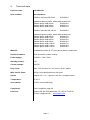
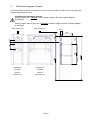
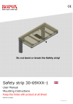
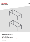
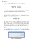
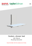
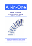
2 VertiElectric User manual Mounting instruction Keep this folder with product at all times! PDF 6010 / 01.11.2009 Table of Contents TABLE OF CONTENTS ..................................................................................................................................................1 TABLE OF CONTENTS ..................................................................................................................................................2 1. INTRODUCTION......................................................................................................................................................3 2. COMPLIANCE WITH EU-DIRECTIVES ...........................................................................................................3 3. APPLICATION ..........................................................................................................................................................3 4. TECHNICAL DATA .................................................................................................................................................4 5. SCHEMATIC DIAGRAM OF FRAME ................................................................................................................5 5.1 Tips and tricks ..................................................................................................................................................6 5.1.1 Tension of bolt connections to wall.................................................................................................................6 5.1.2 Pulling of cables for control............................................................................................................................6 6. MOUNTING INSTRUCTIONS, ILLUSTRATIONS ..........................................................................................7 6. MOUNTING INSTRUCTIONS, DESCRIPTIONS .......................................................................................... 12 6.1 6.2 6.3 6.4 6.5 6.6 6.7 6.8 6.9 6.10 Marking of wall ............................................................................................................................................. 12 Reinforcement of wall units.......................................................................................................................... 12 Marking of holes in wall unit........................................................................................................................ 12 Mounting of safety stop plate........................................................................................................................ 12 Mounting of Verti unit................................................................................................................................... 12 Mounting of wall units .................................................................................................................................. 13 Mounting of motor......................................................................................................................................... 13 Placing of cables for safety stop................................................................................................................... 13 Mounting of safety stop plate........................................................................................................................ 13 Connection of cables..................................................................................................................................... 13 7. PERFORMANCE TEST........................................................................................................................................ 14 8. LIST OF COMPONENTS FOR VERTIELECTRIC ....................................................................................... 15 9. OPTIONS FOR VERTIELECTRIC.................................................................................................................... 16 10. SAFETY IN USE..................................................................................................................................................... 17 11. CLEANING AND MAINTENANCE................................................................................................................... 17 11.1 11.2 11.3 Cleaning of frame.......................................................................................................................................... 17 Maintenance .................................................................................................................................................. 18 Service schedule, operation and maintenance ............................................................................................ 18 12. TROUBLE SHOOTING ........................................................................................................................................ 19 12.1 The height of the frame cannot be adjusted (adjustment seems very difficult) ......................................... 19 13. CE-MARKING ........................................................................................................................................................ 19 14. COMPLAINTS ........................................................................................................................................................ 20 Page 2 1. Introduction VertiElectric is a electric height adjustable frame for wall units. VertiElectric is especially suitable for wheelchair users or persons who normally have difficulties reaching upper shelves in wall units. This document must ALWAYS accompany the product and be read by and available to users All users must follow these instructions. It is very important that the instructions have been read and understood prior to operation of the product. This instruction must be accesseble to the user and keept with the product if it is moved to another place. If this product is electrically adjustable in height there is a risk of trapping. The product must therefore always be operated by or under the guidance of an experienced adult, who has read and understood the importance of section 10 “Safety in use” The correct use, operation and inspection are decisive factors for efficient and safe performance. 2. Compliance with EU-Directives This product has CE-marking according to the current Machinery, EMC and Low Voltage Directives and thus complies with the basic safety requirements. See separate CE-declaration, section 13 . If these frames are assembled or otherwise connected with other electrical components, this will be considered a new unit. Consequently, the assembled unit must be subject to a risk assessment, after which the CE mark may be awarded. 3. Application VertiElectric is designed to obtain optimum working height for the user. VertiElectric has been designed for height adjustment of wall units. VertiElectric must NOT be used as a lifting table or person lifter. The product must be used indoor, under normal room temperatures and humidity as stated in section 4. The control unit complies with IP32/ll and must always be installed in accordance with the national Heavy Current Regulations or corresponding national or international standards. Page 3 4. Technical data Product name: VertiElectric Item numbers: Item numbers: Width of wall units 30-59 cm : 30-40603-9 Additional bottom profile, same width as wall unit! Bottom profile width 30cm 30-40610-9 Bottom profile width 40cm 30-40611-9 Bottom profile width 50cm 30-40612-9 Width of wall units 60-120 cm : 30-40606-9 Additional bottom profile, same width as wall unit! Bottom profile width 60cm 30-40613-9 Bottom profile width 70cm 30-40614-9 Bottom profile width 80cm 30-40615-9 Bottom profile width 90cm 30-40616-9 Bottom profile width 100cm 30-40617-9 Bottom profile width 110cm 30-40618-9 Bottom profile width 120cm 30-40619-9 Material: Welded steel tubes St. 37 and various plastic components. Surface treatment: Blue chromate, powder coating. Power supply: 230VAC / 2,5A / 50Hz Standby primary: 1W Control voltage: 24VDC Duty circle.: Max. 10% conform to 1 min. active / 9 min. pause Max. load of frame: 80 kg evenly distributed over the frame Speed: Approx. 33 mm/sec - Approx. 9 sec for a complete stroke Temperature: 5-45° C Air humidity: 5-85% (non-condensing) Complaints: See Complaints, page 20 Producer: Ropox A/S, DK-4700 Naestved, Tlf.: +45 55 75 05 00 E-mail: [email protected] - www.ropox.com Page 4 5. Schematic diagram of frame Its important that electrical connections to control unit are flexible and can move freely within the range of adjustment of frame. Conditions for schematic diagram: Height of wall units = 704 mm – (with another height of wall unit regulate diagram accordingly) Height of upper edge of wall unit = 2120 mm (if another height required, regulate diagram accordingly) 230V connection 50 ± 1 VertiElectric 30-40606 wall unit 300-500 mm wall unit 600-1200 mm Page 5 * 2120 704 * 1672 VertiElectric 30-40603 Height of wall unit 704-914 300 330 128 60 39 448 150 230V connection 5.1 Tips and tricks 5.1.1 Tension of bolt connections to wall 80 Kg incl. wall unit The maximal load must be evenly distributed in the entire wall unit. As example we have put max load in front edge of wall unit. This calculation presupposes fixation of 11 bolts. 80 x 38 19 x 11 19 cm Tension upper bolts: = 14,5 Kg/bolt Safety factor must be used: Safety factor 1 Safety factor 2 Safety factor 3 15 Kg/bolt 30 Kg/bolt 45 Kg/bolt This is subject to min. 11 bolts having optimum fixation to wall. 38 cm 5.1.2 Wiring to control switch Pull down cable from wall units to edge of worktop for placement of control. We recommend a build-in pipe in wall where the cable can be pulled through (ø3cm). If a high wall unit is placed right next to a VertiElectric, it is an advantage to pull the cable for the control trough wall unit then a pipe in wall can be avoided. Page 6 6. Mounting instructions, illustrations Assembly must always be carried out by competent personnel Prior to assembly check that all parts have been provided. See list of components, section 8 Height of top wall unit (edge) = 2120 mm – see schematic diagram page 5 *1672 mm From the Floor Wall unit centre 6.1.1 6.1.2 6.1.3 6.1.4 1602 mm From the floor 1672 mm From the floor ////////////// ////////////// ////////////// 6.2.1 6.2.2 Page 7 3 x Marking 6.3.1 6.3.2 3 x ø12 1 x ø30 1x Marking 6.3.3 6.3.4 1 x Distance washer 6.4.1 6.4.2 Page 8 9 x screws 6.5.1 6.4.3 6.5.3 6.5.2 418 40 6.5.4 Page 9 Ø 12 (4x) 6.5.5 62 Fastening in top and bottom 6.6.1 6.6.2 Bottom of Cabinet Top of Cabinet 6.6.3 6.6.4 6.7.1 6.7.2 Page 10 Short cable to upwards movement (”Red”) 230V Cable Motor Cable Press pad Y-Cable Long Cable for downwards movement (”Yellow”) Plug w/resistor (red) 6.7.3 6.7.4 Placement of cable to Safety stop plate Placement of Plug w/resistor 6.8.1 6.8.2 230V Flexible main cable Flexible connection to press pad 6.9.1 6.10.1 Page 11 6. Mounting instructions, descriptions Prior to assembly check that all parts have been provided. See list of components, from page 8. See mounting illustrations from page 6 6.1 Marking of wall 6.1.1 A wall unit height of 704mm – mark centre measurement of wall unit on wall in a height of 1672mm from floor. Se schematic diagram page 5 for correct marking.! Drill hole and insert raw plug. 6.1.2 Fasten mounting plate with a screw in the middle. 6.1.3 Level mounting plate in correct height whereupon marking for remaining screws is carried out. 6.1.4 Secure mounting plate with remaining screws which are necessary. 6.2 Reinforcement of wall units 6.2.1 Bottom profile to be hooked onto the frame. 6.2.2 Mount the bottom profile with the two screws. 6.3 Marking of holes in wall unit 6.3.1 Place wall unit on the floor with the backside turned upwards, position VertiElectric on top of the wall unit in the centre. 6.3.2 Mark 3 holes trough the frame and gear box, be careful not to damage any parts of VertiElectric. 6.3.3 Mark one hole in the top of wall unit. 6.3.4 Finally drill all 4 holes (3 x ø12) - (1 x ø30) 6.4 6.4.1 Mounting of safety stop plate 6.4.2 Turn wall unit upside down, whereupon safety stop plate is positioned thus its metal frame is level with the wall units front edge and sides. It might be necessary to place a washer under the metal frame at the middle fastening. Mount all screws around the frame 6.4.3 Secure all 9 screws 6.5 Mounting of Verti unit 6.5.1 Lift VertiElectric onto mounting plate and adjust that it is placed in the centre of the wall unit, Mark additional 2 mounting holes. Remove VertiElectric before drilling and inserting of raw plugs. 6.5.2 Once more lift VertiElectric onto mounting plate, place and adjust in centre of wall unit. Secure the frame with mounting one screw in centre. 6.5.3 Adjust the frame plumb with the 2 adjustment screws which are placed at bottom coil/cylinder. Use 1 in each side. 6.5.4 Insert and fasten remaining 2 adjustment screws. Page 12 6.5.5 6.6 Mark up the Four holes in the back panel of the wall unit for later adjustment according to 6.5.3 & 6.5.4 Mounting of wall units 6.6.1 Lift wall unit onto frame and place in centre. 6.6.2 Secure wall unit in top and bottom. 6.6.3 Press wall unit into frame and fasten the top first. 6.6.4 Press wall unit into frame at the bottom and fasten. 6.7 Mounting of motor 6.7.1 Motor, with spindle, is mounted through back plate and into gearbox 6.7.2 Safely turn the shaft for correct mounting of motor. Tighten the two screws. 6.7.3 Mount cables in control box and motor as shown 6.7.4 Place control box on upper shelve, which is placed as high as possible in wall unit 6.8 Placing of cables for safety stop 6.8.1 Cable for safety stop is drawn from control box through the hole at the top of the cabinet. The cable is placed long the left side of the cabinet and connected to the wire from the safety stop frame. 6.8.2 Secure other end of cable for safety stop with strip in the right side. Note that a “red” short-circuit plug has to be mounted. 6.9 6.9.1 6.10 Mounting of safety stop plate Mount safety stop plate from below and fasten safety stop to metal frame. Note! The safety stop plate should be able to move freely after mounting for it to function as anti trapping. Connection of cables 6.10.1 Secure flexible 230V cable to upper edge of wall unit and to the wall. Lead cable for control switch under tabletop and connect to control switch which should be fitted in the front fascia. Page 13 7. Performance test After installation and prior to use all functions of unit must be tested. The test must be carried out by competent personnel. Subsequently the test shall be carried out once a year. 1. 2. 3. 4. 5. 6. 7. 8. 9. Testing prior to connection to mains voltage: Check that mounting instructions have been observed Check that all bolts have been tightened. Check that all cables have been connected correctly and that the plugs have been pressed home. Check that there is no load on the frame. Check that there is nothing preventing the frame from moving freely within the height adjustment range. Now connect mains voltage to the control unit: Press DOWN on the control switch and move the frame to bottom position. Press DOWN again and keep the switch depressed for approx 5 sec. to reset control box. Check that the movement is even and smooth. Make sure that main cable follow the movement and can move freely. Press UP on the control switch, move the frame to the top position and check that the movement is even and smooth. Make sure that main cable follow the movement and can move freely. If safety stop has been mounted under the wall unit it must be tested as follows: Press DOWN on control switch and let frame move 2-5 cm downwards together with safety stop. The frame must stop downwards movement and move 1-2 cm upwards and stop. If a smart box has been mounted – (is used if a FlexiElectric has been mounted below this unit) follow additional instructions for smart box. If all test are ok, the frame is ready for use. See section 10 “Safety in use”. Page 14 8. List of components for VertiElectric VertiElectric unit 30-40603-9: 1 pc. The VertiElectric comprises: 30*40601-079 Mounting parts, VertiElectric 30*40601-096 Mounting plate Additional choice of Bottom profile: 30-40610-9 Bottom profile width 30cm 30-40611-9 Bottom profile width 40cm 30-40612-9 Bottom profile width 50cm 1 set 1 pc. 1 stk. 1 stk. 1 stk. Motor for VertiElectric incl. fitting 30-40675-9: 1 pc. The motor comprises: 96000573 Cable for motor 10098-453 Fitting for motor 98000-555 Stop ring 96000582 Spindle 7mm, Hex7, L=0,14cm 95170508 Facet washer M8 95010510 Insex screw M5x10 95091050 Screw ø4,8x50 Torx 95000009 Allen key Hex2 1 pc.. 1 pc. 1 pc. 1 pc. 1 pc. 3 pcs. 2 pcs. 1 pcs. Control box (21,2x10,5x6,0 cm) 30-40650: Incl. hose connection (300 cm) 1 pc. The control box comprises: 98002014 Y- cable 98002013 Plug w/resistor 1 pc. 2 pcs. 93000161 Extension cord 300 cm + spiral For mains cable, white 1 pc. 93000162 Extension cord 350 cm + spiral For control switch, white 1 pc. 30-67840 Standard switch, (3x6 cm) Incl. 150 cm cable 1 pc. VertiElectric additional parts 30*40601-098: 1 set. Additional part for VertiElectric comprise: 95000044 Bits 95000037 Open-end spanner NV 7mm 95000004 Allen key NV 4mm 95134017 Chip board screw 95170508 Facet washer M8 10098-498 Support angle 30*40601-116 Nails for support angle 1 pc. 1 pc. 1 pc. 14 pcs. 1 pc. 4 pcs. / 8 pcs. 40 pcs. / 75 pcs. VertiElectric unit 30-40606-9: 1 pc. VertiElectric comprises: 30*40601-079 Mounting parts, VertiElectric 30*40601-099 Mounting plate 1 set 1 pc. Page 15 Additional choice of Bottom profile: 30-40613-9 Bottom profile width 60cm 30-40614-9 Bottom profile width 70cm 30-40615-9 Bottom profile width 80cm 30-40616-9 Bottom profile width 90cm 30-40617-9 Bottom profile width 100cm 30-40618-9 Bottom profile width 110cm 30-40619-9 Bottom profile width 120cm 1 stk. 1 stk. 1 stk. 1 stk. 1 stk. 1 stk. 1 stk. Parts supplied as above. 9. Options for VertiElectric Split cable 96000629: To be used if more than one control 1 pc. Infra-red control 30-67847: Remote control via infra-red receiver (cable 250 cm) Range 150-200 cm Large press pad (14x7 cm) 30-67841: For disabled people, incl. 150 cm cable 1 pc. 1 pc. Safety stop plate 30-416xx-9: Safety circle with extension cable (cable 250 cm) Steel plate with mounting parts and plate. 1 pc. Halogen spot 12V 10W 30-41631-9: Incl. transformer. Mounting hole Ø54 cm, cable 200 cm for trafo. 1 pc. Halogen spot 12V 10W 30-41632-9: Incl. transformer. Mounting hole Ø54 cm, cable 200 cm for trafo. 1 pc. Halogen spot 12V 10W 30-41633-9: Incl. transformer. Mounting hole Ø54 cm, cable 200 cm for trafo. 1 pc. Halogen spot 12V 10W 30-41634-9: Incl. transformer. Mounting hole Ø54 cm, cable 200 cm for trafo. 1 pc. Smartbox 30-69001-9: 1 pc. Option for safety stop plate To be ordered if VertiElectric is mounted above a FlexiElectric Extension cord 30-67870: 1 pc. 250 cm (black) for safety stop Spiral extension 30-67871: L =25-100 cm (black) for safety stop 1 pc. Page 16 10. Safety in use The VertiElectric should only be used by people who have read and understood these instructions.. VertiElectric is a height-adjustable frame, and we recommend the filling of a safety stop beneath in order to guard against trapping. Even though a safety stop plate has been mounted always make sure that there are no people, animals or objects under the frame during height adjustment. VertiElectric is a wall unit and must not be used as lifting equipment or person lifter. Always use the frame so there is no risk of damage to people or property. The person, who operates the frame, is responsible for avoiding damage or injury. Children and people with reduced observation must only operate the frame under surveillance. If the frame is used in publicly accessible locations where children or people with reduced observation ability may get close to the frame, the person operating the frame must pay sufficient attention in order to prevent dangerous situations. Make sure that there is free space above and below the frame to allow height adjustment. Do not overload the frame and make sure that the load distribution is correct. Do not operate the frame in case of errors or damage. Do not use the frame in an explosive environment. In case of inspections, service and repairs make sure the frame is not loaded, and that main power is disconnected Any modification to the frame, which may influence its operation or construction, is forbidden Installation, service and repairs must only be carried out by competent personnel. If the frame has not been installed in accordance with these mounting instructions, the guarantee may become void. Only use Ropox original spare parts as replacement parts. If other spare parts are used, the guarantee may become void. 11. Cleaning and maintenance 11.1 Cleaning of frame The frame must not be connected to the mains voltage during cleaning. Do not flush electrical components with water Clean the frame with a damp cloth using lukewarm water and ordinary cleaning agents. Do not use Corrosive/abrasive liquids or abrasive cloths, brushes or sponges. After cleaning dry the frame. Page 17 11.2 Maintenance Inspections, service and repairs must be carried out by competent personnel The frame is maintenance-free and moving parts have been lubricated for life. For reasons of safety and reliability we recommend inspection of the frame once a year: Check that all bolts have been tightened. Check that the frame moves freely from bottom to top position without problems. Resetting the frame: Press DOWN on the control switch and move the frame to the bottom position. Press DOWN once more and keep the switch depressed for 5 sec. to reset the control unit. Check that the movement is even and smooth. Make sure that the mains cable moves freely. Check that all cables have been fitted correctly and are undamaged.. After each inspection the service schedule shall be filled in. Only use Ropox original spare parts as replacement parts. If other parts are used, the guarantee may become void 11.3 Service schedule, operation and maintenance Service and maintenance No.: Serial Service and maintenance No.: Date: Date: Sign: Sign: Remarks: Remarks: Service and maintenance No.: Serial Service and maintenance No.: Date: Date: Sign: Sign: Remarks: Remarks: Page 18 Serial Serial 12. Trouble shooting 12.1 The height of the frame cannot be adjusted (adjustment seems very difficult) Check mains and voltage to the control unit and that the power is switched on. Check cables and plug-in connections between control box and motors. Check cables and plug-in connections between control box and control switch. Check cable connections between safety stop plate, and control box. (see mounting instructions 6.7.5). (If no safety stop has been fitted, a short-circuit plug must be mounted to both safety stop cables (See mounting instruction 6.7.5). If a safety stop has been mounted: Check that safety stop has not been activated. Move short-circuit plug from safety stop to Y-cable in control box. See mounting instruction 6.7.5). If the frame functions without connection to safety stop, the safety stop is activated. 13. CE-marking Product name: VertiElectric Item no: Item no: Width of wall unit 30-59 cm : Width of wall unit 60-120 cm : 30-40603-9 30-40606-9 Conform with the following directives and standards: Directives The Council Directive No. 89/392/EØF, concerning Machinery, modified by Directive No. 98/37/EF The Factories Inspectorate’s notice No. 561 from 24. June 1994 subsequent modifications. 73/23EEC, Low voltage directive, modified by 93/68/EEC 89/336/EEC, EMC-Directive, modified by 92/31/EEC and 93/68/EEC STANDARDS DS/EN ISO DS/EN ISO DS/EN 12001-1: 12100-2: 527-2: 2003 2003 2002 DS/EN DS/EN DS/EN DS/EN DS/EN DS/EN 61000-6-3:2001, EN 55022 Class B 61000-3-2:2001, EN 61000-3-3:1995, A1:2001 61000-6-2:2001, EN 61000-4-2, -3, -4, -5, -6, -8, -11. Declarations of Conformity can be supplied upon request. Page 19 55014-1: 55014-2: 60335-1 : 2000 1997 2002 14. Complaints We refer to our general Terms of sale and delivery on our homepage www.ropox.com Keep this folder with product at all times ROPOX A/S Ringstedgade 221 DK – 4700 Naestved Tel.: +45 55 75 05 00 Fax.: +45 55 75 05 50 E-mail: [email protected] www.ropox.com Page 20