1
CoCon Installation and User Manual
Installation and User Manual
All information in this document is subject to change without notice. No part of
this document may be reproduced or transmitted in any form or by any means,
electronic or mechanical, for any purpose, without the express written permission
of Televic NV.
Copyright © 2014 Televic Conference NV. All rights reserved.
Title
Author
Creation Date
History
Cocon – Installation and User Manual
JV – EVC – KMA
2012/05/31
2014/11/26 Updated info for v3.2 release
2014/09/04 CoCon v3.2 Plixus Engine added
2014/05/08 CoCon v3.1 revision + features added
2013/07/19 CoCon v2.1 features added
2013/04/18 Final v2.0 info & features added
2013/01/31 Additional v2.0 info added
2012/09/25 CoCon v2.0: Authentication, Voting, … added
2012/05/31 T-Cast Connector added
2012/02/01 Initial Version
.
Televic Conference Systems
2014-12-12
2
Installation and User Manual
Table of Contents
Table of Contents
Table of Contents .................................................................................................................................... 3
Section 1 – General Information ........................................................................................................... 11
1
Copyright Statement ..................................................................................................................... 12
2
Trademarks .................................................................................................................................... 13
3
General description ....................................................................................................................... 14
3.1
General system architecture ................................................................................................. 14
3.2
Server application .................................................................................................................. 14
3.3
Client applications ................................................................................................................. 14
3.4
Typical room setup ................................................................................................................ 15
Section 2 – Installation .......................................................................................................................... 17
4
System requirements .................................................................................................................... 18
4.1
4.1.1
Server application .......................................................................................................... 18
4.1.2
Client applications ......................................................................................................... 18
4.1.3
Network ......................................................................................................................... 18
4.2
5
Hardware requirements ........................................................................................................ 18
Software requirements ......................................................................................................... 19
Installation procedure ................................................................................................................... 20
5.1
Prerequisites.......................................................................................................................... 20
5.2
Installer .................................................................................................................................. 20
Section 3 – Application description ....................................................................................................... 22
6
7
License ........................................................................................................................................... 23
6.1
License modules .................................................................................................................... 23
6.2
Use License in CoCon............................................................................................................. 25
6.2.1
Advantages .................................................................................................................... 25
6.2.2
Practical ......................................................................................................................... 25
Server............................................................................................................................................. 30
7.1
Room configuration wizard ................................................................................................... 30
7.1.1
Welcome page ............................................................................................................... 30
7.1.2
Conference system setup .............................................................................................. 30
7.1.3
Database ........................................................................................................................ 33
Televic Conference Systems
2014-12-12
3
Installation and User Manual
7.1.4
Room selection .............................................................................................................. 42
7.1.5
Advanced settings ......................................................................................................... 43
7.1.6
WCAP+ in coupled mode ............................................................................................... 45
7.1.7
Finish.............................................................................................................................. 45
7.2
7.2.1
Info................................................................................................................................. 46
7.2.2
License ........................................................................................................................... 46
7.2.3
System ........................................................................................................................... 46
7.2.4
Database ........................................................................................................................ 46
7.2.5
Clients ............................................................................................................................ 47
7.2.6
T-Cast ............................................................................................................................. 47
7.2.7
Log ................................................................................................................................. 47
7.3
8
9
Room server window............................................................................................................. 45
Additional configuration for Plixus Multimedia Engine ........................................................ 47
7.3.1
Gain reduction ............................................................................................................... 47
7.3.2
IDC interface language and regional settings ................................................................ 48
Shared client components............................................................................................................. 50
8.1
Login window ........................................................................................................................ 50
8.2
General Settings .................................................................................................................... 52
8.2.1
Language setting............................................................................................................ 52
8.2.2
Remember Server .......................................................................................................... 53
8.3
Manual................................................................................................................................... 53
8.4
Status bar............................................................................................................................... 54
8.5
Date chooser ......................................................................................................................... 55
Room configurator ........................................................................................................................ 57
9.1
Synoptic concept ................................................................................................................... 57
9.1.1
Units .............................................................................................................................. 59
9.1.2
Nodes............................................................................................................................. 61
9.1.3
Background .................................................................................................................... 62
9.1.4
Locking of the room....................................................................................................... 63
9.2
Detect units ribbon................................................................................................................ 63
9.3
Edit synoptic ribbon............................................................................................................... 64
9.3.1
Edit ................................................................................................................................. 65
9.3.2
Page ............................................................................................................................... 65
9.3.3
Grid ................................................................................................................................ 65
Televic Conference Systems
2014-12-12
4
Installation and User Manual
9.3.4
9.4
Background .................................................................................................................... 65
Assign units ribbon ................................................................................................................ 66
9.4.1
Wizard............................................................................................................................ 66
9.4.2
Select ............................................................................................................................. 66
9.4.3
Add nodes ...................................................................................................................... 66
9.4.4
Remove nodes ............................................................................................................... 67
9.4.5
Associate........................................................................................................................ 67
9.4.6
Disassociate ................................................................................................................... 67
9.5
Edit nodes ribbon .................................................................................................................. 67
9.5.1
Label location ................................................................................................................ 67
9.5.2
Label font size ................................................................................................................ 67
9.5.3
Node priority ................................................................................................................. 68
9.5.4
Badge Writer ................................................................................................................. 68
9.6
General functions and hot keys............................................................................................. 68
9.7
Special functions.................................................................................................................... 69
9.7.1
Confidea CU: units with a badge reader........................................................................ 69
9.7.2
Confidea CU: units with voting buttons ........................................................................ 71
9.7.3
CPU 5500: split combined units .................................................................................... 72
9.8
Other Settings........................................................................................................................ 73
9.8.1
General Settings ............................................................................................................ 73
9.8.2
Camera Settings: CPU5500 ............................................................................................ 74
9.8.3
Camera Settings: other Central Units ............................................................................ 75
9.8.4
Camera Settings in combination with TREX .................................................................. 76
10
Meeting Manager ...................................................................................................................... 78
10.1
Delegate concept................................................................................................................... 78
10.2
Database management ......................................................................................................... 78
10.2.1
Main screen ................................................................................................................... 79
10.2.2
Delegates ....................................................................................................................... 81
10.2.3
Chipcard Badge Writer .................................................................................................. 84
10.2.4
RFID Badge Reader ........................................................................................................ 86
10.2.5
Authority........................................................................................................................ 87
10.2.6
Optional fields ............................................................................................................... 94
10.2.7
Groups ........................................................................................................................... 96
10.3
Meeting concept ................................................................................................................... 98
Televic Conference Systems
2014-12-12
5
Installation and User Manual
10.4
File menu ............................................................................................................................... 99
10.4.1
New meeting ............................................................................................................... 100
10.4.2
Existing meetings ......................................................................................................... 100
10.4.3
Tools ............................................................................................................................ 101
10.4.4
Settings ........................................................................................................................ 102
10.5
Home tab and ribbon .......................................................................................................... 103
10.6
Import/Export format .......................................................................................................... 106
10.6.1
Standard XML .............................................................................................................. 106
10.6.2
Word docx format ....................................................................................................... 106
10.6.3
Readable XML .............................................................................................................. 106
10.7
Meeting tab ......................................................................................................................... 109
10.7.1
Title .............................................................................................................................. 109
10.7.2
Description .................................................................................................................. 110
10.7.3
Date of the meeting .................................................................................................... 110
10.7.4
Meeting login method ................................................................................................. 110
10.7.5
Meeting agenda editing during meeting ..................................................................... 111
10.7.6
Advanced ..................................................................................................................... 111
10.7.7
T-Cast. .......................................................................................................................... 112
10.8
Delegate list tab................................................................................................................... 112
10.9
Agenda tab .......................................................................................................................... 114
10.9.1
General agenda item functionality .............................................................................. 116
10.9.2
Lecturer agenda item .................................................................................................. 116
10.9.3
Voting agenda item ..................................................................................................... 116
10.10
Translate meeting tab ..................................................................................................... 125
10.10.1
Define languages ..................................................................................................... 125
10.10.2
Translate meeting.................................................................................................... 126
10.11
Speech timer tab ............................................................................................................. 128
10.11.1
Meeting timer.......................................................................................................... 129
10.11.2
Agenda item timer ................................................................................................... 129
10.11.3
Group speech timer ................................................................................................. 129
10.11.4
Delegate speech timer............................................................................................. 131
10.12
Documents tab ................................................................................................................ 132
10.12.1
Document preview .................................................................................................. 133
10.12.2
Document overview ................................................................................................ 134
Televic Conference Systems
2014-12-12
6
Installation and User Manual
10.13
Services tab...................................................................................................................... 134
10.14
Synoptic tab ..................................................................................................................... 136
10.15
Offline functionality ......................................................................................................... 138
10.15.1
Offline Database Management ............................................................................... 139
10.15.2
Offline Meeting Management ................................................................................. 140
10.15.3
Offline Synoptic ....................................................................................................... 140
11
Operator Application ............................................................................................................... 143
11.1
Meeting concept ................................................................................................................. 143
11.1.1
Open prepared meeting .............................................................................................. 144
11.1.2
Create new meeting .................................................................................................... 145
11.1.3
Main screen ................................................................................................................. 147
11.1.4
Closing the Operator Application ................................................................................ 148
11.2
Operator Application views ................................................................................................. 148
11.2.1
Views and user profile ................................................................................................. 148
11.2.2
Room synoptic ............................................................................................................. 151
11.2.3
Delegate list ................................................................................................................. 160
11.2.4
Agenda ......................................................................................................................... 164
11.2.5
Statistics....................................................................................................................... 168
11.2.6
Screen Control ............................................................................................................. 172
11.2.7
Messages ..................................................................................................................... 174
11.2.8
Documents .................................................................................................................. 177
11.3
Ribbons ................................................................................................................................ 178
11.3.1
Home ribbon................................................................................................................ 178
11.3.2
Audio settings .............................................................................................................. 180
11.3.3
Voting ribbon ............................................................................................................... 181
11.3.4
Edit Agenda ribbon ...................................................................................................... 185
11.3.5
Speech Time ribbon ..................................................................................................... 185
11.3.6
Synoptic ribbon............................................................................................................ 186
11.3.7
Delegate ribbon ........................................................................................................... 187
11.3.8
Statistics ribbon ........................................................................................................... 187
11.3.9
Screen control ribbon .................................................................................................. 191
11.3.10
Messages ribbon...................................................................................................... 191
11.3.11
Documents ribbon ................................................................................................... 192
11.4
Diagnostics information ...................................................................................................... 193
Televic Conference Systems
2014-12-12
7
Installation and User Manual
11.5
12
General functions and hot keys........................................................................................... 194
Signage Application ................................................................................................................. 195
12.1
Signage wizard ..................................................................................................................... 195
12.1.1
Choose the room ......................................................................................................... 196
12.1.2
Choose which screen to use ........................................................................................ 197
12.1.3
Signage screen layout .................................................................................................. 197
12.1.4
Customize Signage Screen Font Size ........................................................................... 199
12.1.5
Customize Signage Screen Colours.............................................................................. 201
12.1.6
Voting Display Options ................................................................................................ 202
12.1.7
Automatically start Signage Application ..................................................................... 206
12.1.8
Choose the blank screen ............................................................................................. 207
12.1.9
Signage Logo ................................................................................................................ 208
12.1.10
Key combination ...................................................................................................... 209
12.2
Closing the signage .............................................................................................................. 210
12.3
Starting the signage ............................................................................................................. 210
13
Audio Application .................................................................................................................... 211
13.1
File menu ............................................................................................................................. 211
13.1.1
Show active configuration ........................................................................................... 212
13.1.2
New configuration ....................................................................................................... 212
13.1.3
Open configuration...................................................................................................... 213
13.1.4
Save configuration ....................................................................................................... 213
13.1.5
Import/Export configuration ....................................................................................... 214
13.2
Home ribbon........................................................................................................................ 215
13.3
Routing inputs ..................................................................................................................... 216
13.3.1
Inputs for routing processing ...................................................................................... 217
13.3.2
Routing input groups ................................................................................................... 218
13.4
Routing outputs ................................................................................................................... 220
13.4.1
Outputs for routing processing ................................................................................... 221
13.4.2
Routing output groups ................................................................................................ 222
13.5
Routing ................................................................................................................................ 223
13.5.1
Routing matrix ............................................................................................................. 223
13.5.2
Standard audio configuration ...................................................................................... 225
13.5.3
Advanced audio configuration example...................................................................... 226
13.6
Audio Application offline ..................................................................................................... 228
Televic Conference Systems
2014-12-12
8
Installation and User Manual
14
T-Cast Connector ..................................................................................................................... 229
14.1
Room Server ........................................................................................................................ 230
14.1.1
Room configuration wizard ......................................................................................... 230
14.1.2
Room server window................................................................................................... 232
14.2
Meeting Manager ................................................................................................................ 233
14.3
Operator Application ........................................................................................................... 235
15
FAQ .......................................................................................................................................... 236
15.1
How to add a license onto Confidea Gen 3 or Plixus .......................................................... 236
15.2
How can I change the language of the CoCon applications? .............................................. 240
15.3
How do I connect the CoCon software to my Televic Central Conference Unit? ............... 241
15.4
The clock on UniCOS multimedia units is not correct. ........................................................ 242
15.5
How do I define a synoptic for my meeting room? ............................................................. 243
15.5.1
How do I define a background image for the room synoptic? .................................... 243
15.5.2
How to initialize or retrieve the microphones connected to the Central Unit? ......... 244
15.5.3
How do I create microphone nodes in the synoptic?.................................................. 244
15.6
How can I change a delegate into a chairman?................................................................... 244
15.7
How do I quickly start a meeting? ....................................................................................... 245
15.8
How do I quickly start a vote? ............................................................................................. 247
15.8.1
Instant Voting based on a voting template ................................................................. 247
15.8.2
Create and configure new voting item ........................................................................ 248
15.9
Where can I see the voting results? .................................................................................... 251
15.10
Why doesn’t the voting session start? ............................................................................ 253
15.11
How do I manage my delegate database? ...................................................................... 253
15.11.1
How do I create and manage delegates? ................................................................ 253
15.11.2
How do I add delegates to the meeting? ................................................................ 254
15.11.3
How do I add delegates to a seat in the synoptic?.................................................. 255
16
Known Issues ........................................................................................................................... 255
17
XSD files ................................................................................................................................... 258
17.1
Import/Export delegates ..................................................................................................... 258
17.2
Import/Export prepared meeting information ................................................................... 261
17.3
Export meeting statistics ..................................................................................................... 262
18
Camera Protocols .................................................................................................................... 263
18.1
Overview.............................................................................................................................. 263
18.1.1
RS232 communication ................................................................................................. 263
Televic Conference Systems
2014-12-12
9
Installation and User Manual
18.1.2
TCP/IP communication ................................................................................................ 264
18.1.3
UDP communication .................................................................................................... 264
18.2
Protocols.............................................................................................................................. 265
18.3
Commands for TLVCAM1 protocol (TLV)............................................................................. 266
18.3.1
18.4
Examples...................................................................................................................... 267
Commands for TLVCAM2 protocol (Philips) ........................................................................ 268
18.4.1
Examples...................................................................................................................... 268
18.5
Commands for TLVCAM3 protocol (EP BXL) ........................................................................ 269
18.6
Commands for TLVCAM4 protocol (EP BXL + Name) .......................................................... 270
18.7
Commands for TLVCAM5 protocol (ARBOR) ....................................................................... 271
18.8
Commands for TLVCAM6 protocol (Rumine) ...................................................................... 272
18.9
Commands for TLVCAM7 protocol (Timestamp) ................................................................ 274
18.10
Commands for TLVCAM8 protocol (Philips + Start&Stop Vote) ...................................... 275
18.10.1
Examples.................................................................................................................. 275
Table of figures .................................................................................................................................... 276
Televic Conference Systems
2014-12-12
10
Installation and User Manual
Section 1 – General Information
Televic Conference Systems
2014-12-12
11
Installation and User Manual
1
Copyright Statement
No part of this publication or documentation accompanying this product may be reproduced in any
form or by any means or used to make any derivative such as translation, transformation, or
adaptation without the prior written permission of the publisher, except in case of brief quotations
embodied in critical articles or reviews. Contents are subject to change without prior notice.
Copyright© 2014 by Televic NV. All rights reserved.
The authors of this manual have made every effort in the preparation of this book to ensure the
accuracy of the information. However, the information in this manual is supplied without warranty,
either express or implied. Neither the authors, Televic NV, nor its dealers or distributors will be held
liable for any damages caused or alleged to be caused either directly or indirectly by this book.
Televic Conference Systems
2014-12-12
12
Installation and User Manual
2
Trademarks
All terms mentioned in this manual that are known to be trademarks or service marks have been
appropriately capitalized. Televic NV cannot attest to the accuracy of this information. Use of a term
in this document should not be regarded as affecting the validity of any trademark or service mark.
Televic Conference Systems
2014-12-12
13
Installation and User Manual
3 General description
This document is a manual for the CoCon software suite of Televic. It contains a description of the
various components, as well as giving information about the functionality of the applications it
consists of.
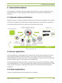
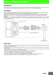
3.1 General system architecture
The goal of CoCon is to provide a complete software suite for conference management, that provides
an intuitive user experience and that allows for flexible setups due to the client-server architecture.
In the image underneath you see the client-server architecture of the system.
Figure 3-1 CoCon overview
3.2 Server application
The server application is responsible for the communication with the central conference unit and is
hence typically installed on a machine located in a server room. In that way, it enjoys the same
power advantages as the central unit itself. The server application is meant to be active continuously;
turning it off and on again for each meeting is not recommended.
The server application allows connection to any type of central conference unit (CPU5500, Confidea
CU, Confidea WCAP Gen 1, 2 and 3, Plixus Engine CU) and keeps track of the conference activity. Next
to that, it makes connection to a database which allows to store and load data pertaining to the
conference.
3.3 Client applications
Currently, the following types of client applications are available:
Televic Conference Systems
2014-12-12
14
Installation and User Manual
Room configurator: this is the application where the room synoptic is created, where the
microphones are allocated to the seats etc.
Operator Application: this is the application that is used during a meeting by eg. a chairman
or operator. It allows to monitoring and steering the microphone activity and other
conference settings.
Signage Application: this allows showing the conference activity on eg. a screen in the
conference room containing the room synoptic, the speaker list etc.
Meeting Manager: in this application, it is possible to create a meeting up front and specify
its details. Additionally, a database with all delegate information can be accessed and edited.
Audio Application: this application allows you to configure the audio routing in the Televic
Plixus Multimedia Engine. This includes the following actions: creating groups of audio input
and output components (microphones, auxiliary input/output, Dante input/output, …);
visualising the various routing groups as a matrix and controlling the audio routing matrix.
API: the Room Server can publish an API which allows to control the meeting from a third
party device. It lets you start a meeting, activate microphones, go through the agenda etc.
For more details about the API, see the document “CoCon API.pdf” that has been installed
with the CoCon installation, in the Help-folder.
In order to activate the API, see Section 7.1.5.
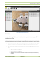
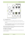
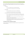
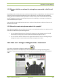
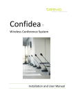
3.4 Typical room setup
The figure below shows a possible setup of a conference room, using the CoCon software suite. This
figure shows a number of delegates on the left-hand side, and an operator on the bottom right-hand
side. The delegates can see changes the Signage Applications (screens in the room), controlled by the
operator using this Operator Application. All client applications are connected to the CoCon Room
Server, which provides connectivity to the conference Central Unit.
Televic Conference Systems
2014-12-12
15
Installation and User Manual
Figure 3-2 Typical conference room setup
Televic Conference Systems
2014-12-12
16
Installation and User Manual
Section 2 – Installation
Televic Conference Systems
2014-12-12
17
Installation and User Manual
4 System requirements
4.1 Hardware requirements
4.1.1 Server application
Processor: Intel i5 2 GHz or higher
RAM: minimum 4 GB
Free disk space: minimum 10 GB
Network connectivity: at least 100 Mb/s
4.1.2 Client applications
Processor: Intel dual-core 2 GHz or higher
RAM: minimum 4GB
Recommended graphical hardware supporting DirectX 9.0 or better.
Free disk space: minimum 10 GB
Network connectivity: at least 100 Mb/s
Note that, when running multiple client applications on the same PC, at least 2GB per client
application needs to be provided.
The following languages are fully supported:
English
French
Spanish
Russian
Italian
Chinese (Simplified)
Dutch
The following languages are partially supported:
Chinese (Traditional)
Japanese
Vietnamese
4.1.3 Network
Network requirements for the following Central Units (connecting over TCP/IP):
Televic Conference Systems
2014-12-12
18
Installation and User Manual
CPU5500
Confidea WCAP+ Gen 1 & 2
Confidea WCAP+ Gen3
Plixus Engine
For these central units following network requirements apply:
Available bandwidth of at least 10Mb/s for each CoCon Room Server/Central unit
connection.
Available bandwidth of at least 10Mb/s for each CoCon Room Server/client connection.
Certain network topologies do not allow the auto-Room Server discovery. A manual setting is
available, see Section 8.1.
4.2 Software requirements
Operating systems supported:
Windows XP SP3
Windows Server 2003 SP2
Windows Vista SP1 or later
Windows Server 2008 (not supported on Server Core Role)
Windows 7
Windows 8
Each PC installed with a CoCon component (any client application or the Server) should also be
provided with the .Net Framework 4.0. This will be installed automatically when CoCon is being
installed.
Televic Conference Systems
2014-12-12
19
Installation and User Manual
5 Installation procedure
The installation of CoCon is performed by executing the file CoConInstaller-RELEASE<VersionNumber>.exe. This will guide you through a typical install wizard with some configuration
options. It is recommended that this installation is performed by technically trained personnel.
Note that it is necessary to let this installation be performed by a Windows user with
Administrator rights.
5.1 Prerequisites
In order to be able to install CoCon, a number of other installed programs are necessary. These are
Microsoft .NET Framework 4.0. This framework is included in the installer package and will
be installed automatically if needed.
Windows Installer 4.5. During installation of the SQL Server Express (the database that CoCon
uses to store its data), Windows Installer 4.5 is needed. This is a software component that
might not be present on older Windows versions. Therefore, the necessary files are installed
with the CoCon suite, and are included in the CoCon installation at
C:\Program Files (x86)\Televic Conference\CoCon\Server\WindowsInstaller4_5 (or similar for
your installation). You can manually install this when the SQL Server Express setup specifies
that these are necessary.
5.2 Installer
The installer of CoCon itself consists of various steps; the most important ones are:
License Agreement.
Choose components: here it is possible to select which components of the CoCon software
suit will be installed on the current PC. Bear in mind that there is usually only 1 Server per
meeting room and only 1 meeting room per Server.
The various client applications that will be installed can also be selected here. Note that the
functionality of the applications plays a role: it is e.g. rather illogical to install the Room
Configurator on a machine which will only be used for signage – installing only the Signage
Application is better suited here. You can position the mouse over any of the client
applications to see a description in the text box on the bottom.
Choose install location.
Installation is performed.
The final step allows you to view the release note. Here some remarks are located regarding
the current installation version.
Televic Conference Systems
2014-12-12
20
Installation and User Manual
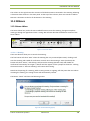
During the installation, Windows firewall will ask your permission to let this program communicate.
Make sure that you allow all connections for the CoCon applications.
Icons for the selected installed applications can be found on the Desktop and in the Start menu.
Televic Conference Systems
2014-12-12
21
Installation and User Manual
Section 3 – Application description
Televic Conference Systems
2014-12-12
22
Installation and User Manual
6 License
The CoCon software needs a license issued by Televic in order to function.
6.1 License modules
The following license modules are available:
CoCon Discussion. It contains all functionality that is required to run a conference system in a
discussion-only situation. It is perfect for corporate board meetings and council meetings
that do not require electronic voting or simultaneous interpretation. Important functionality
is delegate management, meeting construction and control, microphone control, …
Applications included here are the Room Server, Operator Application and Meeting Manager.
CoCon Signage: CoCon Signage is the display application within the CoCon Control suite. It is
a plugin for CoCon Discussion, so the latter is required to run CoCon Signage. CoCon Signage
can be used to display information to the delegates in the room using large screens or
projectors.
The license of the CoCon Signage specifies how many signage screens can be simultaneously
active.
CoCon T-Cast Connector: The T-Cast Connector plug-in integrates the T-Cast on-line
management and control environment into the CoCon Conference Control software. It offers
a seamless synchronisation between the CoCon meeting preparation and the on-line
webcasting environment, as well as control of the T-Cast during a live meeting from the
CoCon Operator Application.
Note that this is a plugin for CoCon Discussion, so the latter is required to run CoCon the TCast Connector.
CoCon Authentication: This module contains the interaction of CoCon with badges. If this
module is present, badges can be read from and written to. For each delegate, a badge can
be created with which he can identify himself to the system.
Note that this is a plugin for CoCon Discussion, so the latter is required to run CoCon
Authentication.
CoCon Voting: The Voting module contains all functionality that relates to the process of
voting. This module will allow to create voting agenda items and templates, start, stop and
control voting sessions and visualize the voting results.
Note that this is a plugin for CoCon Discussion, so the latter is required to run CoCon Voting.
CoCon Configurable Import/Export: This module provides additional functionality to import
and export data to/from CoCon from various formats (XML, Word), as well as providing
advanced printing features.
Televic Conference Systems
2014-12-12
23
Installation and User Manual
CoCon Messages & services: This module adds functionality to the Plixus Multimedia Engine:
with this module, it is possible for the delegates to send messages to one another, and
request configurable services.
CoCon Documents: This module adds functionality to the Plixus Multimedia Engine: with this
module, it is possible to add documents to the meeting. The delegates are able to consult
this document at their leisure, or the Operator can take control of the viewing of these
documents.
CoCon Audio Application: This module allows the usage of the Audio Application. With this
application, it is possible to define audio groups, create a matrix of the audio inputs and
outputs and control the auxiliary and Dante audio inputs and outputs.
Televic Conference Systems
2014-12-12
24
Installation and User Manual
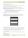
6.2 Use License in CoCon
The license mechanism for CoCon changes depending on the hardware you’re connecting with.
CPU5500,
Confidea Gen 1 and 2
Confidea CU
Simulation plugin
Confidea Gen 3
Plixus Multimedia
• License file based on MAC address of the
Room Server PC
• License located on the Room Server PC
• License based on MAC address of the device
you're connecting with
• License located on the device itself
Figure 6-1 License mechanism for various CU
6.2.1 Advantages
As a customer
•When a PC crashes before the meeting, it suffices to re-install CoCon and start the
meeting, you don't need to request a new license.
•During the meeting you can run a redundant PC into which you have the same
meeting data. Then in case of an unexpected PC error, you can continue the
meeting on the other PC (not seamless).
As an integrator
•You can request and enter the license file already before you actually install the
equipment.
•You don't have to wait until the final PC arrives to obtain that MAC address and request
the license.
As a sales person
•For demo purposes you don't need a license on the PC of each sales person.
Figure 6-2 License mechanism advantages
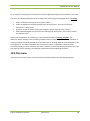
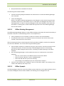
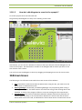
6.2.2 Practical
Televic Conference Systems
2014-12-12
25
Installation and User Manual
There are 2 ways to find the MAC address and add the license file onto your Confidea Gen 3 system:
Use the web page of the CU and do it manually without CoCon (not yet available for Plixus
Multimedia Engines).
Use CoCon and select the correct device type, then you will be guided in the configuration
wizard:
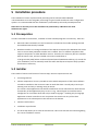
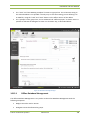
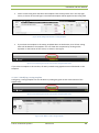
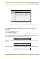
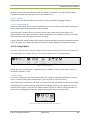
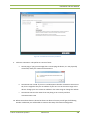
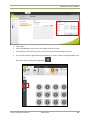
1. After installation of the CoCon Room Server you start the Room Server. Then you will see the
following wizard. Click “Next” to continue.
Figure 6-3 First step of the room configuration wizard
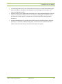
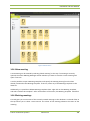
2. Then you have to choose the hardware you will be using with CoCon. When you select
“Conference Simulation Plugin”, “Confidea CU”, “Confidea WCAP+ 2.0 and earlier” or
“CPU5500” and you’ve entered the correct connection parameters (ports, IP addresses) you
will be asked to give a license file based on the MAC address of your PC. In the following we
will proceed with the new mechanism for Confidea 3.0 or Plixus Multimedia Engine.
Televic Conference Systems
2014-12-12
26
Installation and User Manual
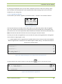
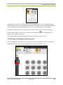
Figure 6-4 Conference system selection
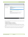
3.
Select your preferred conference system type and enter the correct IP address of the device
you want to connect to.
The default IP for Confidea Gen 3 is 192.168.1.110.
The default IP for Plixus Engine is 192.168.0.100.
The default IP for Confidea Gen 1 and 2 is 192.168.0.10
The default IP for the CPU5500 can be found on the CPU itself under the menu: 4 Settings.
If you cannot connect, please check if your local IP settings (IP address and subnet mask) are
correct.
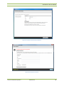
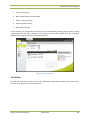
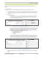
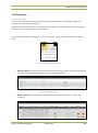
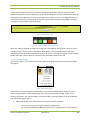
4. When CoCon does detect a device but does not detect a license you will get the following
window. Otherwise you will be able to continue the setup of the Room Configurator.
Televic Conference Systems
2014-12-12
27
Installation and User Manual
Figure 6-5 Confidea 3.0 connection parameters
Figure 6-6 No valid license found
Televic Conference Systems
2014-12-12
28
Installation and User Manual
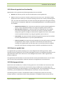
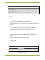
5. When you’ve received the requested license file you can browse for it in this window. Then
you will get the following message:
Figure 6-7 License uploaded successfully
Figure 6-8 Overview of active license modules
Televic Conference Systems
2014-12-12
29
Installation and User Manual
7 Server
The room server is the application which is responsible for the following functionality:
Connection with the central conference unit
Database connectivity
The component to which the various client applications connect
7.1 Room configuration wizard
This wizard is shown when the server is first started, or afterwards if a change to the server
configuration is required. It is built up of the screens shown in the following sections.
7.1.1 Welcome page
Figure 7-1 Welcome to the room configuration wizard
7.1.2 Conference system setup
This screen lets you select the properties for the connection with the central conference unit. A
dropdown box is provided which allows selecting any of the available plugins in the current
installation. Provided plugins are described in the following sections.
Televic Conference Systems
2014-12-12
30
Installation and User Manual
For all CU, you can click the “Test Connection” button at the bottom of this screen to verify your
connection settings to the CU. Note that you can cancel the test if it takes too long. One of two
results will happen:
Connection OK.
Connection not OK. In this case, a link will be shown where you can consult the log files.
7.1.2.1 CPU5500
This component allows connection to the Televic CPU5500 Central Unit. This connection is
established over a standard LAN-connection using the TCP/IP protocol. Parameters here include:
IP-address. This is the IP address of the central conference unit you want to connect to.
The default IP for the CPU5500 can be found on the CPU itself under the menu: 4 Settings.
Port: this is usually port 5011 for the CPU5500.
Figure 7-2 Conference system setup
During connection to the CPU5500, a check is performed if the CPU5500 has a software version
which is high enough to support all the CoCon features. An automatic update procedure is included
Televic Conference Systems
2014-12-12
31
Installation and User Manual
to update the CPU5500. Note however that no firewall or other traffic-blocking programs should be
active during this automatic update process.
Alternatively, you can manually copy the CE5532.EXE (contained typically in C:\Program Files
(x86)\Televic Conference\CoCon\Server) to the CPU5500 (eg. using Total Commander).
7.1.2.2 Confidea CU
This component allows connection to the Televic Confidea Wired (CE2500) Central Unit. This
connection is established using a serial connection over RS232. Parameters here include:
COM-port: specify here the COM-port on the computer to which the serial cable going to the
central conference unit is connected. The other side of the serial cable should be connected
to the port COM 3 on the Confidea Wired Central Unit.
7.1.2.3 Confidea Wireless Generation 1 and 2
This component allows connection to the Televic Wireless Conference Access Point, Generations 1
and 2. This connection is established over a standard LAN-connection using the TCP/IP protocol.
Parameters here include:
IP-address. This is the IP address of the WCAP unit you want to connect to.
The default IP for Confidea Gen 1 and 2 is 192.168.0.10
Port: this is usually port 9000.
7.1.2.4 Confidea Wireless Generation 3
This component allows connection to the Televic Wireless Conference Access Point, Generations 3.
This connection is established over a standard LAN-connection using the TCP/IP protocol. Parameters
here include:
IP-address. This is the IP address of the WCAP unit you want to connect to.
The default IP for Confidea Gen 3 is 192.168.1.110.
Port: this is usually port 5011.
7.1.2.5 Plixus Multimedia Engine
This component allows connection to the Televic Plixus Multimedia Engine. This connection is
established over a standard LAN-connection using the TCP/IP protocol. Parameters here include:
IP-address. This is the IP address of the WCAP unit you want to connect to.
The default IP for Plixus Engine is 192.168.0.100.
Port: this is usually port 5011.
The Plixus Multimedia Engine allows to have multiple virtual rooms on one central unit. That’s why
CoCon shows a box to select the “Room ID”. It is mandatory to click the “Test Connection”-button.
CoCon will then try to connect to the Plixus Engine and retrieve the available room IDs. CoCon will
automatically select the best possible room ID if no human intervention is needed. The layout of the
window is shown in the figure below.
Televic Conference Systems
2014-12-12
32
Installation and User Manual
Figure 7-3 Plixus Multimedia Engine connection window
7.1.2.6 Conference Simulation Plugin
This component allows simulating a conference system without actually using the conference
hardware. It will simulate microphone and voting activity, so that the CoCon client applications can
be used as if a real system would be connected.
For more information: see the document “Conference Simulation Plugin.PDF” contained in the Helpdirectory of the CoCon installation or in the Start Menu, under Televic Conference > CoCon > Help.
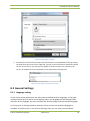
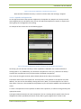
7.1.3 Database
The next steps in the configuration wizard will allow you to choose, create and/or update the database that
CoCon uses to store its data.
During installation of the SQL Server Express (the database that CoCon uses to store its data), a check
is done whether the Computer Name is the same as the User Name. This is a situation which is
considered bad practice in IT terms, and does not allow the successful completion of the SQL Server
installation procedure. In order to remedy this, stop the CoCon Room Server (using Task Manager),
change either the Computer Name or the User Name and restart the CoCon Room Server.
Televic Conference Systems
2014-12-12
33
Installation and User Manual
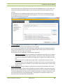
7.1.3.1 Database detection
This step detects any databases that are already present or can be used to run CoCon on. The first
step lets you choose between automatic detection and manual setup.
Figure 7-4 Database setup: recommended or manual
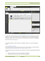
The recommended option will show the following screen, where the CoCon Server is looking for
usable database servers.
Televic Conference Systems
2014-12-12
34
Installation and User Manual
Figure 7-5 Database setup: recommended
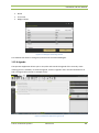
The manual option will show the following screen.
In the top half you can select the database server where from a list, or enter it manually. It also
allows for Windows or SQL Authentication.
The bottom half allows you to install a new database instance, see next section.
Televic Conference Systems
2014-12-12
35
Installation and User Manual
Figure 7-6 Database setup: manual
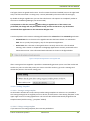
7.1.3.2 No database found: create new database
If no usable database is found, CoCon will recommend creating a new database; this is shown in the
following screen:
Televic Conference Systems
2014-12-12
36
Installation and User Manual
Figure 7-7 Database setup: new database
The following paragraphs describe two possibilities in this situation.
7.1.3.2.1 Install SQL Server Express 2008
No Microsoft SQL Server Express 2008 is installed. The wizard will automatically install this database
component and install a valid instance on the database so CoCon server can function correctly.
Note that this is an automated procedure during which no user input is required. It can however take
some time to complete this operation.
Televic Conference Systems
2014-12-12
37
Installation and User Manual
Figure 7-8 Installing SQL Server 2008 - part1
Figure 7-9 Installing SQL Server 2008 - part2
Televic Conference Systems
2014-12-12
38
Installation and User Manual
Figure 7-10 Installing SQL Server 2008 - part3
7.1.3.2.2 SQL Server Express 2008 installed but no database found
Microsoft SQL Server Express 2008 installed but no instance found. At this point, you should follow
the wizard and allow it to create a new instance.
7.1.3.3 Compatible database found and usable
In this situation, a usable database has been found. CoCon will use this database to store its data.
The screenshot below illustrates this.
Televic Conference Systems
2014-12-12
39
Installation and User Manual
Figure 7-11 Database setup: database found
7.1.3.4 Compatible database found and need to update
Occasionally, the CoCon database will need to be updated. You will be notified of this, using a special
wizard step, as shown in the figure below. The update procedure will take some time to update the
database tables in your database, but no data will be lost.
Televic Conference Systems
2014-12-12
40
Installation and User Manual
Figure 7-12 Database setup: update needed
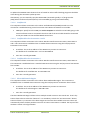
7.1.3.5 Database configuration OK
If you would run through the configuration again and the database is configured correctly, you will see the
following screen.
Clicking on the button “Change database (advanced)” will allow you to change the database, using the steps
described in the previous sections.
Figure 7-13 Database setup: OK
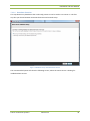
If you click on the “Change database (advanced)” button and then keep the current settings by
clicking “Next”, you will see the following screen:
Televic Conference Systems
2014-12-12
41
Installation and User Manual
Figure 7-14 Database setup: Clear Database
By clicking the button “Clear this database”, all the information contained in the current database is
deleted, so that you can start with a new empty database.
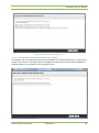
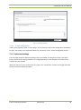
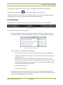
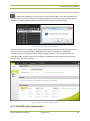
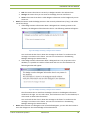
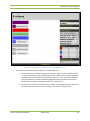
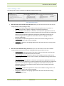
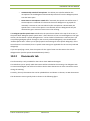
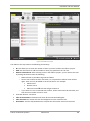
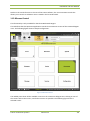
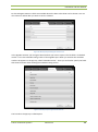
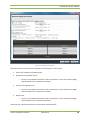
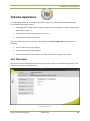
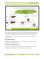
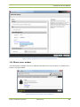
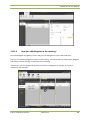
7.1.4 Room selection
7.1.4.1 Room selection
This screen contains the room selection. Here you can create a new room, or connect to an existing
room. In the upper right-hand corner of this window the effects of the action you choose are shown.
To create a new room, fill in name and an optional description in the fields at the top.
If you want to take over an existing room, select any of the room names under “Take over an
existing room”. Be aware that these rooms are already assigned to another server. If you
select this, the current room server will take over the control of the room from the other
server.
Take control of an unassigned room. By selecting any of the names here you can control an
orphaned room (where no CoCon Room Server is associated with it) and assign it to this
server.
Televic Conference Systems
2014-12-12
42
Installation and User Manual
Figure 7-15 Room selection
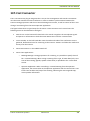
7.1.4.2 T-Cast configuration
If there is an expander called “T-Cast config”, you can click this to fill in the configuration parameters
for the T-Cast setup. For more details about this, see Section 14.1.1 - Room configuration wizard.
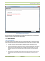
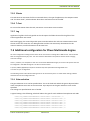
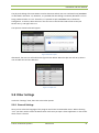
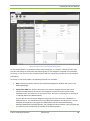
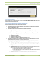
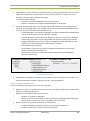
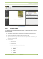
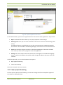
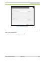
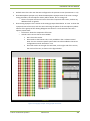
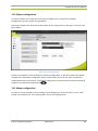
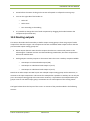
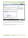
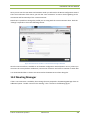
7.1.5 Advanced settings
The next page shows the Advanced settings that are available; an example is shown in the figure
below. Note that the settings available can change depending on the selected CU and the license
modules that are enabled.
When the mouse cursor is hovered over any option, the “Description” section on the right will show
further information about the option.
Televic Conference Systems
2014-12-12
43
Installation and User Manual
Figure 7-16 Advanced settings
The available options include:
General:
o
Check the box “Run the room server at Windows start up” if you want to ensure that
the CoCon server gets started every time this machine starts up. This can be very
convenient for the server application, as no CoCon functionality is available when the
server application is not started.
o
Check the box “Activate the API” to make sure the API is active the next time the
Room Server is started.
Note that the Room Server needs to be started with Administrator Rights to make
sure that the necessary sockets can be opened for the API to function.
API:
Customer specific: this section contains the activation of features that have been developed
specifically for certain customers. This should not be selected for most users.
Voting Management:
Televic Conference Systems
2014-12-12
44
Installation and User Manual
o
Voting buttons: here you can specify if your setup has units with 3 or 5 voting
buttons. This will determine the type of voting items you can create in the client
applications.
Delegate Management:
o
Badge Type: for some type of CUs: here you can choose between chipcard and RFID
card.
o
Badge Option: this allows you to specify how much information should be written on
the badges. The following possibilities are present:
ID only: the badges will only contain the ID of the delegate written on it.
Full badge: in this case, more information will be written to the badge. This
will include the delegate ID, first name, last name, …
T-Cast: see section 14.1.1.
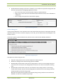
7.1.6 WCAP+ in coupled mode
The following section describes the behaviour of a WCAP+ in slave mode and is only applicable for
the Confidea CU and CPU5500.
If a WCAP+ Central Unit is connected in slave mode to the Confidea CU or CPU5500, then CoCon can
make a parallel connection to this WCAP+ to retrieve additional information about the wireless units.
This additional information consists of the RF and battery status for each of the wireless units. The
Operator Application will then show the states of the wireless units so the operator can quickly see
which of the units is almost out of range or needs to be recharged. Up to 5 WCAP+ Central Units can
be connected in slave mode to a Confidea CU or CPU5500.
In order to make a parallel connection to a WCAP+, the IP address of the WCAP+ needs to be
configured in the Conference system setup. See Figure 7-2 for the configuration of the IP addresses.
Click on the column “Value” of the table to enter the IP addresses of one or more WCAP+.
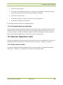
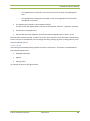
7.1.7 Finish
After completing the room configuration wizard, a restart of the server is needed. The server will
restart automatically.
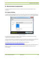
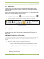
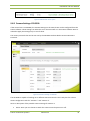
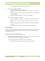
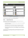
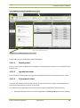
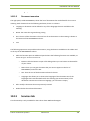
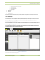
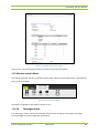
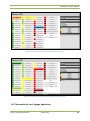
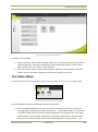
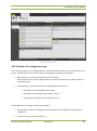
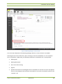
7.2 Room server window
When the room server is active, an icon will appear in the task bar notification area:
or
Right-clicking on this icon gives access to one of three functions:
Room server: see below.
Televic Conference Systems
2014-12-12
45
Installation and User Manual
Configuration wizard: see previous section.
Exit: shuts down the room server.
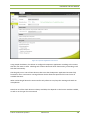
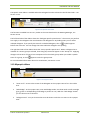
The room server window is shown below.
Figure 7-17 Room server window
7.2.1 Info
This tab contains information about the name of the server, the server version, Room Server IP
address and the protocol version.
7.2.2 License
This tab contains the expiration date of the license, an overview of the enabled licenses, and the
possibility to change your license to another.
7.2.3 System
This tab contains information about the current connection with the central conference unit, its
name, description and current status (Connect, Disconnect).
By pressing the button “Restart System Connection”, the connection with the conference system is
restarted.
By pressing the button “Reboot Central Unit” (if applicable), the central unit to which this Room
Server is connected will be rebooted.
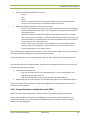
7.2.4 Database
This tab shows the connection state and version of the database.
Televic Conference Systems
2014-12-12
46
Installation and User Manual
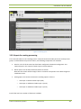
7.2.5 Clients
This tab shows an overview of all the connected clients, the type of application, the computer name
and “last alive check”, which indicates when their connection was last verified.
7.2.6 T-Cast
For more information about this tab, see Section 14.1.2 Room server window.
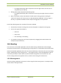
7.2.7 Log
Application log files: the first hyperlink in this tab opens the folder where all the log files of the
CoCon applications are stored.
Real-time logging: the second hyperlink opens a window where the real-time communication with
the CU can be seen. Note this is a debug window and thus not extensively documented in this
manual. However, useful information can be seen here.
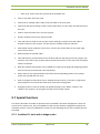
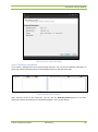
7.3 Additional configuration for Plixus Multimedia Engine
All of the configuration settings for the Room Server are saved to a settings file in XML format. This file should
NOT be changed manually by users. The user interfaces described in the previous sections allow changing
almost all settings.
There is, however, one exception to this rule: for the Plixus Multimedia Engine, there are a few options that can
be configured in this XML settings file. The file can be found here:
C:\Users\<USER>\AppData\Local\Televic Conference\CoCon\CoCoSServerConfig<GUID>.xml
or similar for your configuration.
The following sections describe the settings that can be set manually here. To enable these settings, add the
described lines to the configuration file.
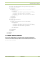
7.3.1 Gain reduction
The gain reduction curve can be specified here. This is the level with which the gain is adjusted when
more microphones are active at the same time. Up to 8 points in the gain reduction curve can be
specified.
The settings are specified with units of 0.1dB.
A typical setting is the following, which will reduce the gain for each additional microphone with 1dB.
<Setting
<Setting
<Setting
<Setting
<Setting
<Setting
<Setting
Name="GainReductionCurveP1"
Name="GainReductionCurveP2"
Name="GainReductionCurveP3"
Name="GainReductionCurveP4"
Name="GainReductionCurveP5"
Name="GainReductionCurveP6"
Name="GainReductionCurveP7"
Televic Conference Systems
2014-12-12
Value="0" />
Value="-10" />
Value="-20" />
Value="-30" />
Value="-40" />
Value="-50" />
Value="-60" />
47
Installation and User Manual
<Setting Name="GainReductionCurveP8" Value="-70" />
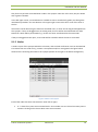
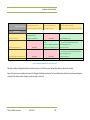
7.3.2 IDC interface language and regional settings
The Plixus Multimedia Engine allows the delegates to change their interface language or regional
settings on the IDC itself. However, it may also be necessary that ALL the IDC’s in a room are put to
the same interface language and/or regional settings. That is the reason that the following two
settings are available:
<Setting Name="CD_CHANGE_INTERFACE_LANGUAGE" Value="1" />
<Setting Name="CD_CHANGE_REGIONAL_SETTINGS" Value="1" />
The first setting CD_CHANGE_INTERFACE_LANGUAGE will change the language of the IDC interface
on each meeting start (including resuming of the meeting). The values that can be set here are
described in the following table:
Televic Conference Systems
Description
Value (integer)
English
0
Suomi
1
Italiano
2
Russian/русский
3
Deutsch
4
Arabic/ال عرب ية
5
Chinese/中文
6
Français
7
Japanese/日本人
8
Korean/한국의
9
Vietnamese/Việt
10
Português
11
Nederlands
12
2014-12-12
48
Installation and User Manual
The second setting CD_CHANGE_REGIONAL_SETTINGS will change the regional settings of the
keyboard on the IDC on each meeting start (including resuming of the meeting). The values that can
be set here are described in the following table:
Description Value (integer)
Televic Conference Systems
US English
0
Suomi
1
Belgisch
2
2014-12-12
49
Installation and User Manual
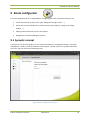
8 Shared client components
This section contains a description of all the components which are shared among the client
applications.
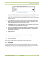
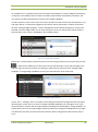
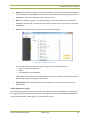
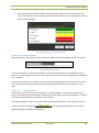
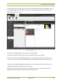
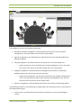
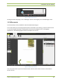
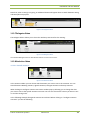
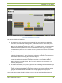
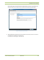
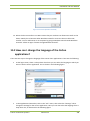
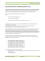
8.1 Login window
In order for the client applications to function, they need to connect to the conference room server.
Therefore, a login dialog appears when starting up the application. This is shown in the figure below.
Figure 8-1 Login dialog
This dialog allows selecting the language in which the application is displayed (this can also be
changed within the applications, see Section 8.2).
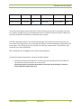
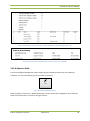
The CoCon clients contain an auto-detection mechanism by which they automatically search for any
active CoCon servers. These are shown in the dialog, and you can select one to logon to.
The protocol used is WS-Discovery. More information can be found here:
http://msdn.microsoft.com/en-us/library/dd352335.aspx
The multicast address used is 239.255.255.250 on IPV4 networks and [FF02::C] on IPV6 networks. In
both cases, multicast messages are sent to port 3702. More information can be found in the
following figure:
Televic Conference Systems
2014-12-12
50
Installation and User Manual
Source IP
Source Port
Destination IP
Destination Port
Protocol
Client request
10.0.40.81
50729 [varies]
239.255.255.250
3702
UDP
Server response
10.0.41.108
3702
10.0.40.81
50729 [varies]
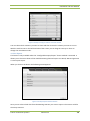
UDP
Figure 8-2 WS-Discovery information
In case the CoCon Room Server(s) that are currently running are not shown in the dialog, there may
be a network configuration (eg. a firewall blocking ports or traffic) that does not allow it. Make sure
the traffic needed for the discovery is allowed on your network.
Check the “Remember Server” box to automatically login to the selected server the next time you
start up this client application. You can change this setting in the General Settings, as described in the
Section 8.2.2. This setting will also be removed if you click the “Logout admin” at the bottom righthand side of the client applications.
After clicking OK, you are logged in to the CoCon client application.
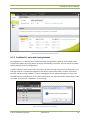
The following advanced parameter is present (see figure below):
Manually provide the host address: This means that you manually enter the IP-address or
the server host name in the box “IP or Host name”.
Note that you have to check the box marked “Use these manual settings” in order for
these advanced settings to be used.
Televic Conference Systems
2014-12-12
51
Installation and User Manual
Figure 8-3 Login dialog: advanced
Note that the servers that have been manually filled in are remembered locally. By clicking
the drop-down box arrow on the right side, you get a view of all previous manually entered
servers. If you click on any of them, they appear in the box and you can connect to the
server, on condition that you checked the “Use these manual settings” box.
Figure 8-4 Login dialog: advanced server tracing
8.2 General Settings
8.2.1 Language setting
All the CoCon client applications are able to be translated to other languages. In the loginwindow (section 8.1) as well as in the Settings-menu, the language can be changed. After
selection of the language, the user interface will directly change into the selected language.
As can be seen in the figure below, selection of the current user interface language is
available in the File-menu, in the section Settings. Here you can select your preferred
Televic Conference Systems
2014-12-12
52
Installation and User Manual
language to view the current CoCon application in. For availability of more languages than
those presented here, contact your Televic contact person.
Figure 8-5 General Settings
This setting will be saved per application, so the next time you start the same client application, the
same language will be used for the interface.
If you want to have CoCon translated in more languages than are currently available, please contact
your Televic Conference contact person. In cooperation with Televic Conference, it is possible to
provide CoCon in other languages as well.
8.2.2 Remember Server
This option shows if there is currently a default remembered Room Server for this application. You
can select here if you want to remember or forget the default Room Server. If you select “No” here,
the client application will ask you to specify the server to log on to when next starting up.
On the right-hand side, the default Room Server is shown.
8.3 Manual
Televic Conference Systems
2014-12-12
53
Installation and User Manual
In the File-menu, under the Help-menu, a button is available which will open this Help-file.
Alternatively, you can click the
icon in the upper right corner of the screen.
There is also a PDF-version located in the installation folder; it can be reached using the WindowsStart Menu folder, under Televic Conference\CoCon\Help\CoCon Manual.
8.4 Status bar
At the bottom of most CoCon client applications, you will see the status bar. It looks like this:
Figure 8-6 Status bar
This component contains (from left to right):
Connections status: this icon shows the status of three connections. If the icon is white, no
connection problems are present. By double-clicking on it, the following window appears:
Figure 8-7 Connection states window
Three components are shown here (if applicable):
o
Server connection state: status of connection with the CoCon server application.
o
Conference system connection state: the status of the connection with the central
conference unit.
Note that for Plixus, this state presents the connection state to a room on the
Central Unit, not to the Central Unit as such. When first connecting CoCon to a new
Plixus Multimedia Engine, the status will be Disconnected until the initialization has
been done successfully (see Section 9.2).
o
Database connection state
o
T-Cast connection state
Faults status: this icon shows if there are any faults. This can e.g. be microphone faults as
well as errors with the connection states described above. Each error has a timestamp when
it occurred. The following colour code is used:
Televic Conference Systems
2014-12-12
54
Installation and User Manual
o
Yellow background: the fault has occurred and has not yet been solved
o
Green background: the fault has occurred and has been solved.
Twos button at the top allow clearing the solved faults from the list, as well as clearing the
entire list.
Figure 8-8 Fault list window
Televic icon
Meeting symbol
Name of the room
Logout button: this button logs you out of the current session, and lets you connect to
another room server. This will also forget the currently remembered default Room Server; so
you will be able to specify which other server you want to connect to next time.
8.5 Date chooser
In several of the CoCon client applications, date choosers are present (eg. to select the start time of a
meeting or the birth data of a delegate). Three of views of this can be seen in the figure below.
Figure 8-9 Language setting
In the text field representing the date, you can manually fill in the date (by using numbers and /), or
you can click the
icon next to the field to open the drop-down date chooser.
Televic Conference Systems
2014-12-12
55
Installation and User Manual
The first view in the figure above shows the way to pick a date in any month. The currently selected
month is shown first. By clicking the left and right arrows next to the month, you can navigate
through the months. After clicking on a day in a month, this date is selected and the chooser closes.
If you want to navigate over longer periods of time, click the month/year combination at the top of
the chooser. This will result in the second view of the figure which allows you to pick a month in the
current year, or navigate the year using the left and right arrows.
Clicking once again on the year at the top of the date chooser, you will get a view of the years that
are available. Clicking on a year will select it, and return to the month view, etc.
Televic Conference Systems
2014-12-12
56
Installation and User Manual
9 Room configurator
This is the application which is responsible for configuring the room; some of its functions are:
Create and edit the synoptic of the room (background image, colour, …)
Automatic or manual detection of conference units (microphones, voting units, badge
readers, …)
Placing of the conference units on the synoptic
Designation of chairman/delegate property
9.1 Synoptic concept
A synoptic is a set of room graphics. It can contain microphones, a background image… The Room
Configurator is used to create and edit the room synoptic. Initially, there is no synoptic attached to
the room, and you will see the following screen.
Figure 9-1 Room configurator start screen
Televic Conference Systems
2014-12-12
57
Installation and User Manual
After defining a name for the synoptic and clicking “Create new”, you will enter the Room
Configurator itself. A few concepts here are crucial to understand how to define the synoptic of your
meeting room:
Unit: a unit is a representation of a physical conference unit connected to the central
conference unit. This can e.g. be a microphone, a voting panel, a camera… Each of these can
be placed on the room synoptic by attaching them to a node.
Node: a node is a location in the room, where a person/delegate/meeting attendee can take
a seat.
On a node, a number of conference units can be associated. This can be a microphone, a
voting panel, a badge reader… This means that a node can contain more than one unit.
A node is a part of the synoptic which has a location, and to which conference units can be
attached.
Background: the background image of your synoptic. This can be a picture or a diagram of
the conference room.
The following screen shows an example of the Room Configurator. It contains 10 units (shown on
the left-hand side), and 5 nodes (shown on the right-hand side). The objects themselves are
visible in the middle, the synoptic itself.
Of the 10 units, 4 are associated with a node in the synoptic (shown in green), 6 are not yet
associated (shown in red).
Televic Conference Systems
2014-12-12
58
Installation and User Manual
Figure 9-2 Room configurator main screen
9.1.1 Units
The units represent the physical units connected to the central conference unit. This can e.g. be a
microphone, a voting panel, a camera… Each of these can be placed on the room synoptic by
attaching them to a node.
They are controlled on the left hand side of the Room Configurator; this table contains the data and
columns described below. Note that the headers in this table can be clicked upon to sort the content.
Nr: this is the ID that the system uses to identify this unit. It also corresponds to the order in
which the unit buttons have been pushed during manual initialization (see Section 9.2).
Type: this describes the type of the conference unit. The following unit types can be shown
here:
o
MIC: this stands for microphone.
o
DCS: this stands for voting panel.
o
MIC&DCS: this is a unit which combines microphone and voting functionalities (eg.
Confidea).
Televic Conference Systems
2014-12-12
59
Installation and User Manual
Capabilities: this column shows the capabilities this specific unit has, using abbreviations. The
following are available:
o
M: Microphone
o
C: Chairman
o
V: Voting functionality
o
B : Badge reader
o
LCD: language LCD
Note that these abbreviations are concatenated into one string. Eg. MCVB means a
Microphone with Chairman functionality, Voting buttons and a Badge reader.
A description and a filter are also available by clicking on the icon
in the header of the
table. Here the abbreviations are shown in full. Additionally, by checking and unchecking the
boxes, the list with all units is filtered to only contain the units with the checked capabilities.
This can also be seen in the figure below.
The figure below shows a list of 10 units; 4 are MIC&DCS, 3 MIC and 3 DCS.
Figure 9-3 Units in the system
Units are constructed by interacting with the central conference unit. This is the component that
controls the conference objects in the conference room. They can be initialized automatically or
manually (see 9.2). After initialization, they appear in this list with a red indication. This means that
Televic Conference Systems
2014-12-12
60
Installation and User Manual
they have not yet been associated with a node in the synoptic. Once this is the case, they are shown
with a green indication.
In the left upper corner, a wizard button is available to start a wizard which guides you through the
initialization procedure. The two buttons in the upper right corner select all or none of the units in
the list.
Association can be done using the functions described in 9.5, or units can be drag-and-dropped onto
the synoptic. If they are dragged onto an existing node, the unit will be associated with this node.
Note that a check will be performed if e.g. no two vote units are allocated to the same node.
If they are dragged into the open, a new node will be created to which the unit is associated.
9.1.2 Nodes
A node is a part of the synoptic which has a location, and to which conference units can be attached.
This means that one node can e.g. contain a microphone and/or a voting panel. The figure below
shows the list containing the nodes in the synoptic (shown on the right in the Room Configurator).
Figure 9-4 Nodes in the synoptic
Each of the nodes has some characteristics (from left to right):
A ‘+’ shows if any units are associated with it. The number next to it shows how many units it
contains. Clicking on this shows which units are associated:
Televic Conference Systems
2014-12-12
61
Installation and User Manual
Figure 9-5 Nodes in the synoptic detail
Note that, by adding multiple units to the same seat, you will activate the microphone couple
mode. This means that the microphones that are attached to the same node will be activated
and deactivated all at once if any of them are activated /deactivated. This is usually a
function given to chairman positions, so the application will ask if the current node should be
made into a chairman.
Nr: this column shows the number of this node; this is also called the “Seat Number”. Seat
numbers can be changed by double-clicking on them and entering a new number. A check
will be performed to make sure that all seat numbers are unique
Name: by double-clicking on the name contained here, you can edit it. This way it is possible
to assign names to the various nodes present in the synoptic.
Priority: here you can define if a certain seat has delegate or chairman priority. A chairman
gets another icon on the synoptic and can always speak. Double-click on this to get a dropdown list to change the property.
Coordinates: X and Y
Description
Right-clicking on any line in this list of nodes allows you to perform the following actions:
Activate the unit(s) positioned on this seat;
Change the seat number.
For the creation of nodes, see 9.3, for the association of units to nodes, see 9.5.
9.1.3 Background
The background image of the synoptic is typically a photograph or a graphic representation (plan,
diagram) of the conference room. Here the nodes can be placed to indicate the physical position of
the microphones in the room. For actions concerning this background, see 9.3.4.
Televic Conference Systems
2014-12-12
62
Installation and User Manual
Figure 9-6 Sample synoptic
9.1.4 Locking of the room
The Room Configurator locks the room it is editing for as long as it is active. This means that:
No other user has access to the Room Configurator. Only one user can edit the room at the
same time.
No CoCon Operator Application has access to the room; no meetings can take place as long
as the room is being edited. This is because the room is in the process of being configured
and it is not allowed to have a meeting here.
Note that if the Room Configurator does not close properly, the room remains in the locked state
and any new instances of the Room Configurator would not have access to the room. It suffices to
restart the Room Configurator to remove this lock.
9.2 Detect units ribbon
This ribbon lets you detect units connected to the central conference unit and load them into the
CoCon Room Configurator.
Televic Conference Systems
2014-12-12
63
Installation and User Manual
Figure 9-7 Detect units ribbon
The first button is the “Save”-button which saves the entire room configuration to the database.
The “Initialization wizard”-button opens a wizard which guides you through the process of
initialization.
The “Start init”-button allows the user to select one of two options:
In the automatic initialization, the central conference unit will detect the units connected to
it automatically, and pass the information to the Room Configurator. This entails that the
user does not need to do anything other than waiting for the units to appear in the left-hand
side of the Room Configurator. The numbering of the microphones in this case has no link to
their physical location, but is based on the underlying cabling of the conference system.
Manual initialization means that all of the microphones will have to be identified by an
action of the user. This usually happens by pushing the microphone-button. This method can
be used if microphones located next to one another should have subsequent numbers.
The “Stop init”-button stops the currently running initialization. This is necessary in a manual init
since the CoCon Room Configurator does not know when all the microphones have been activated.
The “Resume init”-button allows to add units to a previous initialization. This is always a manual
initialization.
The “Retrieve Initialization”-button will request the current initialization from the central unit and
show the initialized microphones in the list with units on the left-hand side.
Note that for the Plixus engine, the initialization can also be done when the Conference system
connection state is Disconnected. This is because this state represents the connection state to a
room on the Central Unit. This room is only created when the initialization process is performed.
9.3 Edit synoptic ribbon
This is the ribbon you see when “Edit Synoptic” is highlighted.
Televic Conference Systems
2014-12-12
64
Installation and User Manual
Figure 9-8 Home ribbon
It contains a number of functionalities; these are described in the following sections.
9.3.1 Edit
Save: this saves the current synoptic with the current settings to the database.
9.3.2 Page
Here you can set the width and height of the page area. This is defined as the “useful” area with in
the synoptic editor. Changing this size can also be achieved by clicking and dragging the bottom right
corner of the page (shown by a small grey rectangle).
9.3.3 Grid
The grid is an overlay to the synoptic editor which allows you to position the objects in a more
structured way.
The button “Show Grid” switches this functionality on and off.
The button “Snap to grid” specifies whether the objects in the synoptic are automatically aligned to
the grid.
The last option allows adjusting the grid size. If the grid size is reduced, it is possible to place the
objects with a greater degree of accuracy.
9.3.4 Background
The functions here control the background image.
Under the button “Signage”, you can access the following functions:
Open new image from file. This opens a file browser where you can select the background
you want.
Reset current image to original. This undoes the editing you performed on the background
and returns the image to the originally loaded file.
Clear current background image. This erases the background image, but keeps the other
components of the synoptic.
Televic Conference Systems
2014-12-12
65
Installation and User Manual
The button “Keep aspect” specifies whether to scale the length of breadth of the figure in a
correlated way.
“Center” places the figure in the middle of the synoptic.
“Fill” expands the figure to fill the entire page area of the synoptic.
“Image width” and “image height” can be set in the next boxes (either entering numerical values or
clicking the up- and down-arrows).
Likewise, “Position left” and “position top” shift the image in the desired direction.
Finally, the button “Background colour” lets you select the colour of the background; this is the area
where the background image does not cover the page area.
9.4 Assign units ribbon
This ribbon lets you construct and manipulate synoptic nodes.
Figure 9-9 Assign units ribbon
9.4.1 Wizard
The first button in the “Wizard”-section, “Node allocation wizard” opens the node allocation wizard,
which will help you to create and/or associate nodes.
The second button “Make synoptic by click”, when toggled, starts a mode in which the unallocated
units (on the left-hand side) are each in turn highlighted. When you click on a location in the
synoptic, a new node is created and the highlighted unit is allocated to that node. This continues
until there are no unallocated nodes left.
The third button “Skip unit” can be used to skip a node when the “Make synoptic by click” is active.
9.4.2 Select
The button “Select all” selects all the nodes currently present in the synoptic view.
The button “Unselect all” deselects any nodes currently selected in the synoptic view.
9.4.3 Add nodes
The functions on the left are options for the adding of nodes.
Amount: specify the amount of nodes that will be added to the synoptic when you click the “Add
nodes”-button.
Televic Conference Systems
2014-12-12
66
Installation and User Manual
Add node by click: if this box is checked, then you will create a node every time you click on the
synoptic.
Node prefix: this is the word that will appear on the synoptic in front of the number. Note that the
node name can be changed manually for each node once the node has been created.
9.4.4 Remove nodes
By clicking this button, you delete the currently selected nodes.
9.4.5 Associate
The button “Auto create seats for all units” creates a new node for each of the units that are not yet
associated to a node. These nodes are created in the upper left corner of the synoptic viewer.
“Auto create seats for selected units” performs the same tasks, but only for the selected units that
are not associated to a node.
The button “Auto position all units for seats” allocates all the non-assigned units (on the left-hand
side) to the seats with the same ID.
9.4.6 Disassociate
“Reset all associations” clears all the unit associations to any node.
“Reset associations for selected units” clears the unit associations for the units that are selected in
the list on the left side of the screen.
“Reset associations for selected nodes” clears the unit associations for all selected nodes in the
synoptic viewer.
9.5 Edit nodes ribbon
9.5.1 Label location
By clicking these buttons after the selection of one or more nodes in the synoptic view, the label
location of the nodes is moved to the direction clicked. This can be useful to arrange the nodes and
their label in a aesthetically pleasing way.
9.5.2 Label font size
By clicking these buttons after the selection of one or more nodes in the synoptic view, the font size
of the labels of the selected nodes is decreased, increased or reset to the default value.
The button “Enable/Disable background” will show or hide a semi-transparent background to the
label. This is to ensure that the text is readable, even with challenging background images.
Televic Conference Systems
2014-12-12
67
Installation and User Manual
9.5.3 Node priority
These two buttons allow to select the priority of the selected node(s). A chairman is a user in a
meeting who has higher priority than the others. This means he can always speak, even when the
speaker-list is full.
By clicking either Delegate or Chairman Priority, the selected priority is set to the selected node. This
will be visible in the Room Configurator in the following ways:
The node icon will look like this:
On the right-hand side, the column “Priority” of the node will change to “Chairman”.
, whereas the delegate nodes look like this:
Figure 9-10 Edit nodes ribbon
This ribbon contains functions to associate detected units to nodes in the synoptic.
9.5.4 Badge Writer
Here you can define the standard badge writer you want to use to write badges. This will then be
selected by default when reading and writing badges for delegates in the Meeting Manager (see
Section 10.2.3).
9.6 General functions and hot keys
This section contains a number of general functions and hot keys that are available within the CoCon
Room Configurator. When you are working in the synoptic viewer, these hot keys are at your
disposal:
Right-click on a node in the synoptic or list allows following actions:
o
Activate unit: this facilitates finding the physical location of the unit in the room.
o
Change seat number: this allows changing the number of the seat. Note that the
number should be unique.
In the upper right corner, there is a zoom control with the following actions available:
o
Mini-map: click to drop down or disappear.
o
Slider: allows zooming in and out.
Televic Conference Systems
2014-12-12
68
Installation and User Manual
o
Zoom to fit: click to have the synoptic fill the available area.
Click on any node: select the node.
CTRL+click on multiple nodes: select all of the nodes at the same time.
CTRL+click and hold and drag: creates a square with which you can select all nodes present in
this area.
CTRL+A: select all nodes in the current synoptic.
Escape: deselects all currently selected nodes.
Click-and-hold any node on the synoptic viewer and drag it around: move the node to
another location on the synoptic. This also works if multiple nodes are selected.
CTRL+wheel mouse up/down: zoom in/out. You can also use the slider on the upper right
corner of the viewer.
Delete: deletes all selected nodes
Click-and-hold any unassociated unit on the left-hand side and drag it onto the synoptic: this
creates a new node on the synoptic and associates the unit with it. This also works if multiple
nodes are selected.
Note that multiple microphones can be added to a single seat by drag-and-dropping multiple
units to the seat (as mentioned in the step above).
Select nodes on the right-hand side of the field: the corresponding nodes in the synoptic
viewer are selected and vice versa.
Each of the green arrows allows you to collapse the top controls, or the left- or right-hand
side components to increase the visible area of the Room Configurator.
Assigning names to seats can be done by double-clicking on the “Name” column in the
“Nodes in the synoptic” on the right-hand side of the synoptic viewer.
9.7 Special functions
This section describes a number of special functions available in the Room Configurator. These are
not meant for common use, but are available to make sure the software configuration reflects the
hardware situation. They are subdivided in sections for the following central units: Confidea CU and
CPU 5500.
9.7.1 Confidea CU: units with a badge reader
Televic Conference Systems
2014-12-12
69
Installation and User Manual
For Confidea CU, it is possible that certain units have the possibility to insert a badge and read/write
it. However, the hardware does not permit to detect this possibility automatically. Therefore, the
user needs to indicate himself which units have the “badge capability”.
In order to do this, select a unit in the Unit List on the left-hand side of the screen (see Section 9.1.1),
and right-click on it. The Room Configurator will show a context menu with a number of functions.
Click the “Change badge capability”, and the message-box shown below will appear to verify if the
selected unit has a badge reader or not. After clicking Yes or No, the functionality will be shown in
the unit table, in the column “Capabilities” (B for Badge reader).
Figure 9-11 Single badge capability
Note that it is also possible to select more than one unit (using the button at the top of the unit view
or CTRL+click or SHIFT+click in the Unit list on the left-hand side). If you select multiple units
and then right-click on any of them, you will get a context menu, where you click “Change badge
capability” to assign badge capabilities to all of your selected units at the same time.
Figure 9-12 Multiple badge capability
Under “File” > “Settings” there is an option in the settings of the Room Configurator that can help in
identifying the various units you want to change the badge capabilities for. See Figure 9-13. If you
check the option “Activate the microphone when indicating units with badge or voting capability”, as
shown below, then the microphone light will be activated if you change the capabilities of any single
unit. Note that this does not work with multi-selection. Other settings will be discussed in section
9.7.4.
Televic Conference Systems
2014-12-12
70
Installation and User Manual
Figure 9-13 Room Configurator Indicator setting
9.7.2 Confidea CU: units with voting buttons
For Confidea CU, it is possible that certain units have voting buttons. However, the hardware does
not permit to detect the voting button presence automatically. Therefore, the user needs to indicate
himself which units have voting buttons.
In order to do this, select a unit in the Unit List on the left-hand side of the screen (see Section 9.1.1),
and right-click on it. The Room Configurator will show a context menu with a number of functions.
Click the “Change voting capability”, and the message-box shown below will appear to verify if the
selected unit has voting buttons or not. After clicking Yes or No, the functionality will be shown in the
unit table, in the column “Capabilities” (V for Voting).
Figure 9-13 Single voting button capability
Televic Conference Systems
2014-12-12
71
Installation and User Manual
Note that it is also possible to select more than one unit (using the button at the top of the unit view
or CTRL+click or SHIFT+click in the Unit list on the left-hand side). If you select multiple units
and then right-click on any of them, you will get a context menu, where you click “Change voting
capability” to assign badge capabilities to all of your selected units at the same time.
Figure 9-14 Multiple voting button capability
There is an option in the settings of the Room Configurator that can help in identifying the various
units you want to change the badge capabilities for. If you check the option “Activate the
microphone when indicating units with badge or voting capability”, as shown below, then the
microphone light will be activated if you change the capabilities of any single unit. Note that this
does not work with multi-selection.
Figure 9-15 Room Configurator Indicator setting
9.7.3 CPU 5500: split combined units
Televic Conference Systems
2014-12-12
72
Installation and User Manual
The physical cabling of the CPU 5500 is used to determine which units are combined units (MIC&DCS
as described in Section 9.1.1). However, it is possible that the cabling erroneously identifies a unit as
being combined when it is not. Therefore, it is possible to split a MIC&DCS unit in the Room
Configurator. To do this, select the unit in the Unit List on the left-hand side of the screen (see
Section 9.1.1), and right-click on it.
The question shown below will appear
Figure 9-16 Unit to split
Afterwards, the Unit List will look like the figure shown below. Note the split unit with ID 2; there is
now one MIC unit and one DCS unit.
Figure 9-17 Split unit
9.8 Other Settings
Under the “Settings” view, there are some other options.
9.8.1 General Settings
Here you can select the language of the program and choose to Remember Server. When choosing
“Yes” you don’t need to select the Room Server each time you open a client application. It also shows
which server is chosen.
Televic Conference Systems
2014-12-12
73
Installation and User Manual
Figure 9-18 Remember Server option
9.8.2 Camera Settings: CPU5500
If the central unit is a CPU5500, the Camera Settings on the Central Unit can be configured from the
CoCon software. These settings can either be set on the CPU itself or in the CoCon software. But it is
advised to apply the settings only on one of these.
The various protocols that can be sent out by the CPU5500 are described in Section 18 Camera
Protocols.
Figure 9-19 Camera Settings on CPU5500
The CPU5500 is capable of sending out 2 different Camera Protocols. That’s why the first column
shows configuration tabs for “Camera 1” and “Camera 2”.
Here’s a description of the possible camera settings for Camera 1:
Status: Here you can choose to switch the camera control option on or off.
Televic Conference Systems
2014-12-12
74
Installation and User Manual
Type: For Camera 1 you have the choice between RS232, TCP/IP and UDP.
Protocol: In total there are 8 protocols to choose from. These all have the same basics
namely: sending a string when a microphone is switched on or off but some give some more
information e.g. Delegates name, Agenda item, etc. For a detailed description of these
different protocols, see Section 18 Camera Protocols.
COM Port: Here you can choose which one of the 2 COM ports you want to use.
COM Speed: By default the communication baudrate is 19200 but this is configurable.
UPD1 and UDP2: these options set the UDP protocol, IP address and port.
Camera 2 can only be configured with type RS232. The other settings are the same.
After configuring the settings don’t forget to press “Save” in order to send your changes to the
CPU.
9.8.3 Camera Settings: other Central Units
If the central unit is not a CPU5500 the Camera Settings can be configured so that the CoCon Room
Server transmits the camera protocol. The various protocols that can be sent out by the CoCon Room
Server are described in Section 18 Camera Protocols.
The following figure shows the interface to configure the camera settings:
Figure 9-20 Camera Settings on Central Unit, other than CPU5500
Note that currently only 1 camera protocol can be sent out by the CoCon Room Server
simultaneously.
The following settings can be configured:
Status: either ON or OFF
Televic Conference Systems
2014-12-12
75
Installation and User Manual
Type: the following possibilities are present
o TCP/IP
o UDP
o Serial
o Protocol: the specific camera protocol that will be sent out by the CoCon Room
Server. For more information, see Section 18 Camera Protocols.
Additional settings, depending on the connection type:
o TCP/IP: for this type of connection, a local TCP Listening Port needs to be configured.
The CoCon Room Server will listen on this local port for incoming connections from
the camera system.
Note that firewalls etc. need be configured so that traffic to this port is possible.
o UDP: for this type of connection, a remote IP-address/port needs to be entered. The
CoCon Room Server will make a UDP-connection to this address/port and send the
camera protocol over UDP to this port.
o Serial: for this type of connection, a local COM-port on the CoCon Room Server
machine needs to be configured. To this local serial port, a serial cable is then
connected that goes to the camera system.
After configuring the settings, be sure to hit the “Save”-button on the right-hand side. This will save
the camera protocol configuration and activate the new settings.
Note that these settings are saved and will be used only after restarting the CoCon Room Server.
The CoCon Room Server installation folder contains two small applications that can be used to test
the following types of connections:
CameraProtocolListener.exe:
o TCP: this tool will connect to the indicated IP/port on the remote machine and
display all activity that is sent out.
o UDP: this tool will listen to the commands sent to the indicated port.
TMSCamPup.exe: this tool will listen to commands being sent on the indicated Serial Port.
These can typically be found under C:\Program Files (x86)\Televic Conference\CoCon\Server (or
similar for your installation).
9.8.4 Camera Settings in combination with TREX
TReX is the Televic Recording software. TReX can take in meta-data originating from CoCon.
TReX can be combined with CoCon by providing the correct camera protocol parameters. For
connection with TReX, the camera protocol TLVCAM5 needs to be selected. Use the settings as
shown in the following figure.
Televic Conference Systems
2014-12-12
76
Installation and User Manual
Figure 9-21 Camera Settings for connection with TReX
Televic Conference Systems
2014-12-12
77
Installation and User Manual
10 Meeting Manager
This section contains a description of the use of the Meeting Manager. This is the application which is
responsible for:
-
Creating and managing the database management. This includes the creation and
management of users, groups, badges, voting rights & weight, creation of authority passes, …
-
Creating a meeting, including the title, time, conference settings, …
-
Specifying the delegates who will be attending the meeting
-
Adding the delegate list to the nodes in the synoptic
-
Creating an agenda for a meeting
-
Creating a voting agenda
-
Specifying the voting settings
-
Specifying the time constraints for various parts of the meeting (speech time for the
delegates and groups, agenda item time, meeting time, …)
Note that the Meeting Manager has need of a synoptic in the room before defining a meeting. This is
necessary because the delegates present should be attributed to a seat. For the definition of a
synoptic, see section 9 or FAQ How do I define a synoptic for my meeting room?
10.1 Delegate concept
A delegate in the CoCon software suite is defined as a person with a number of characteristics (name,
surname, title, address …). A delegate can belong to any number of groups. A group is defined by a
name and (optional) a colour, and have any number of delegates.
When defining a meeting, the delegates that are participating can be defined. As such, there is
knowledge in the system of who participated in what meeting and when.
10.2 Database management
The database management is the part of the Meeting Manager where CoCon allows you to manage
the database with delegates, groups etc. The underlying data is all stored in the central database
connected to the CoCon Room Server. Important to note here is that no delegate data is stored on
the local system; all information entered and modified here is stored in the database, which is
connected to the CoCon Room Server.
The Database Management can be accessed by clicking the right-most button on the Home ribbon of
the Meeting Manager, as shown below.
Televic Conference Systems
2014-12-12
78
Installation and User Manual
Figure 10-1 Home Ribbon
Alternatively, at various locations in the Meeting Manager-application, the Database Management is
available by clicking the following button:
In the Database Management tool, a substantial amount of information is represented in lists
(groups, delegates …). At the top of these lists, a number of functions are available. The figure below
illustrates this.
Figure 10-2 Common list actions
At the top right, two buttons are present to select all (
) or nothing (
) in the list.
Under that, a search box is present which will filter the list when you type text in the box. This will be
instant: the list is filtered as you type the data. Any component of the list below can be entered (if
multiple columns are present). If you have entered text, the icon on the right-hand side of the box (
) will change to an icon that allows you to clear the search terms (
).
Add (
): Click this button to create an empty delegate. All his/her details can be filled in
the right-hand column.
Remove (
): If one or more delegates are selected in the left column, they can be deleted
by clicking this button
The column headers are all sortable. By clicking once, the contents of the list will be sorted
alphabetically according to the clicked column. If you click again, the order will be reversed.
10.2.1 Main screen
After starting the Database Management, the following screen is shown:
Televic Conference Systems
2014-12-12
79
Installation and User Manual
Figure 10-3 Main Screen of the Delegate Management
On the left-hand side, it is possible to select either “Delegates” or “Groups”. Clicking on these tabs,
the view will change to show either the defined groups or the delegates contained in the database.
At the top, in the menu bar, the contextual menus will also change and provide other functionalities
(see below).
At the top, in the Home-ribbon, the following functions are available:
Back: Clicking this button will close the Database Management-window and return to the
Meeting Manager.
Import from TMS: this function will allow you to select a delegate file from the Televic
Conference TMS-software and import the delegates contained into the current CoCon
database format. The extension of this type of file is .del, but it is actually just a renaming of
a .mdb file (MS Access 2003 database).
This can also be used to import delegates and groups for users who have a database in a
different format. The expected format of the MS Access database can be found in a sample
database located under C:\Program Files (x86)\Televic Conference\CoCon\Meeting
Manager\TMSImporter\Sample\Sample_100_Delegates.mdb and Sample_100_Delegates.del
(or similar for your installation). Be mindful of the following items:
Televic Conference Systems
2014-12-12
80
Installation and User Manual
o
The names of the tables (“groups” and “delegates”), as well as the column headers
should not be changed. The import process uses these fields to identify the data
contained.
o
Note that the input file does not have to be renamed to a .del extension; it can also
remain a .mdb format.
Import from …: this button allows you to import delegates from a local file to the central
database. Currently, only a proprietary XML-format is defined as file format for importing
and exporting delegates. This data format is used when exporting (see next bullet).
Export to …: using this button, you can export the delegates and groups contained in the
database to a local file, which you can later import again (using the button described above).
10.2.2 Delegates
The delegates are managed in the first tab of the Meeting Management-tool; click “Delegates” on
the left-hand side of the screen to open this. You will now see the screen as is shown below.
Figure 10-4 Delegate tab
Televic Conference Systems
2014-12-12
81
Installation and User Manual
Two columns are present here: the first (ALL DELEGATES) shows a list of all the delegates currently
contained in the database. The second column (DETAILS) shows the details of the currently selected
delegate in the left column (if any).
In this second column, you can view (and modify) the following details for any delegate:
Title
Badge number: this is a read-only field, generated by the CoCon software suite.
Name
First name
Username
Password
Street
Street number
City
Postal code
Country
District
Date of birth
Email
Phone number
Any optional fields that have been defined. See Section 10.2.6 for more information.
Biography
Vote options:
o
Voting right: check this box if the delegate should be able to vote. By default this box
is checked.
o
Voting weight: when casting a vote, a delegate can have a voting weight which is
different than 1. This can for example be used for:
Delegates with more voting powers than others.
Televic Conference Systems
2014-12-12
82
Installation and User Manual
Delegates that will cast an informative vote; their voting weight can be set to
0.
Authority pass from/to: an overview of the authority passes for this delegate
Groups: a list of all the groups in the current system. A checked box in front of the group
signifies the current delegate belongs to this group.
Picture
The delegates can be added, modified or deleted by pressing the buttons on the Delegate-ribbon as
shown below.
Figure 10-5 Delegate Ribbon
The following buttons are present:
Back: Clicking this button will close the Database Management-window and return to the
Meeting Manager
Add: Click this button to create an empty delegate. All his/her details can be filled in the
right-hand column. This functionality can also be achieved by pressing the hotkey CTRL+N on
the keyboard.
Delete: If one or more delegates are selected in the left column, they can be deleted by
clicking this button.
Edit: after selection of a delegate in the left column, this button allows you to modify its data
in the right column. At that time, the following two buttons are available at the top of the
right column:
. They will allow you to save or cancel your changes.
Saving a delegate can also be achieved by pressing the hotkey CTRL+S on the keyboard.
Find: Searching for a delegate can be done using this functionality. This functionality can also
be achieved by pressing the hotkey CTRL+F on the keyboard. Clicking this button will show
the following window:
Televic Conference Systems
2014-12-12
83
Installation and User Manual
Figure 10-6 Search delegates window
Here you can specify various fields on which the list with delegates will be filtered. Note that
you can enter part of a name or field. Note as well that the search criteria are all applied
(AND-filter). Clicking the “Search”-button at the bottom-right corner will apply your selection
criteria. Afterwards, use the “Remove filter” to clear the filter.
Remove filter: use this button to clear the search criteria describe in the previous step.
10.2.3 Chipcard Badge Writer
Figure 10-7 Chipcard badge writer
This section of the Delegate Management ribbon contains functions to read and write badges. The
following controls are available:
Badge reader: This is a drop-down box containing all units capable of reading and writing a
badge. Select here the device you want to use to read or write. After selection of a unit, a
colour-code will appear next to the drop-down box (you can also hover with the mouse
pointer over the colour to see more information):
Televic Conference Systems
2014-12-12
84
Installation and User Manual
1. Red: this means that there is currently no badge inserted in the selected unit.
2. Orange: this means that you can write to the badge, but not read from it.
3. Green: this means that there is valid delegate information on the badge and you can
write to it.
Read: This button reads the badge present in the currently selected unit (if any), and will do
one of two things:
1. If the badge contains information about a delegate that is already present in the
database, the delegate will be selected in the list. The following window will appear:
Figure 10-8 Badge containing a delegate in the database
You can check the box “Don’t show this message in the future” to make sure the
message is not shown in the future. You can turn this back on in the Meeting
Manager Settings (see Section 10.4.4)
2. If the badge contains information about a delegate that is not yet present in the
database, it is possible to read this information and save it to the database. The
following window will appear:
Figure 10-9 Badge containing a delegate in the database
The information that is read from the badge is shown in the delegate information
window on the right. You can edit it here, and click Save to save it to the database, or
click Cancel to discard the information.
You can check the box “Don’t show this message in the future” to make sure the
message is not shown in the future. You can turn this back on in the Meeting
Manager Settings (see Section 10.4.4)
Write: After selection of a delegate in the list with All Delegates, you can click this button to
write the delegate to the inserted badge of the selected unit.
Televic Conference Systems
2014-12-12
85
Installation and User Manual
10.2.4 RFID Badge Reader
With a number of Central Units (CPU 5500, Confidea Generation 3, Plixus Engines) it is possible to use
RFID badges. CoCon is compatible with RFID badges with 4Byte NUID (like MiFare classic and MiFare
Plus) and 7Byte NUID.
When using RFID badges, no actual data is written on the badge. Instead, the Unique Identifier of the
badge is read and stored in the database. This means that existing RFID applications can still use the
entire data contents of the card.
In that case, the “Badge Writer” section of the Delegates-ribbon looks like the following figure:
Figure 10-10 RFID badge writer buttons
Connect the USB-RFID reader to the PC where you are running the Meeting Manager, and click the
“Refresh readers” button. At that point, you should be able to select the reader and see the
following:
Figure 10-11 RFID badge writer selected
Now the following actions are available:
Select a delegate in the list
Put a badge on or remove a badge from the RFID reader
Using these actions, the following functionality can be accomplished:
Read a badge that is not assigned to a delegate and create a new delegate
1. Put a badge on the RFID reader
2. The selection of the list with all delegates is removed
3. You can enter the data of the new delegate in the panel on the right.
4. Click “Save” when finished. Now a new delegate is created with the badge that was
put on the RFID reader.
Read a badge that is assigned to a delegate:
1. Put the badge of the delegate on the RFID reader
Televic Conference Systems
2014-12-12
86
Installation and User Manual
2. Now the delegate is selected in the list with all delegates.
Write an existing delegate to a badge:
1. Select the delegate in the list with all delegates
2. Click on the “Edit” button in the Delegate-section or the ribbon, or in the Detailssection.
3. Put the badge on the RFID reader. Now the Unique ID is filled in the “Badge number”
field of the delegate.
4. Click “Save”. Now the delegate is associated with the RFID badge.
Remove an existing delegate from a badge:
1. Put the RFID badge on the RFID reader. The delegate is automatically selected in the
list.
2. Click on the “Edit” button in the Delegate-section or the ribbon, or in the Detailssection.
3. Remove the badge from the RFID reader. The “Badge number” field of the delegate
is cleared.
4. Click “Save”. Now the delegate is no longer associated with the RIFD badge.
10.2.5Authority
This part of the Delegate Management-ribbon allows you to create authority passes. This means that
one delegate gives his voting right (and weight) to another delegate for a certain period of time or
the duration of a meeting.
10.2.5.1 Creation of voting authority pass
This section describes how to create a voting authority pass.
Add authority pass/Delete authority pass: Clicking this button will show an additional
window where the creation of an authority pass can be done.
In 5 steps it is possible to pass a voting authority to another delegate.
o
STEP 1: Choose a delegate who will give his voting right to another delegate:
Televic Conference Systems
2014-12-12
87
Installation and User Manual
Figure 10-12 Step 1: Choose a delegate
o
STEP 2: Choose a delegate to give the voting authority to
Televic Conference Systems
2014-12-12
88
Installation and User Manual
Figure 10-13 Step 2: Choose a delegate
o
STEP 3: Choose the authority validation period. This can either be a time period, or the
duration of any meeting that has already been defined in the system.
Figure 10-14 Step 3: Choose the authority validity period
o
STEP 4: Choose a badge number.
An authority badge is defined as a badge that contains only the given voting right of the
first delegate. This badge cannot be used for identification, but is only useful when
voting. After the second delegate has cast his own vote, he can insert the authority
badge in the system to vote with the received authority. As a consequence, this means
that the own vote and the received vote (with the authority pass) can be different.
It will then be registered in the system that this is a voting authority pass from the first
delegate to the second delegate.
Televic Conference Systems
2014-12-12
89
Installation and User Manual
If you don’t create an authority badge, this means that the second delegate will vote only
once, and that his vote will be his own vote and the received authority.
Figure 10-15 Step 4: Choose a badge number
If you select the first option (“Yes, I want to use an authority badge”), you can choose
one of the following actions:
Read: read the badge currently in the selected badge writer. This badge will
then be used as the authority badge for the current authority pass.
Generate: generate a new authority badge and write the relevant
information to the badge currently in the selected badge writer.
Edit: use a previously created authority badge by entering the badge number
of the authority badge.
o
STEP 5: Confirm information
The last step shows an overview of the entered data and lets the user review the data.
Televic Conference Systems
2014-12-12
90
Installation and User Manual
Figure 10-16 Step 5: Confirm Information
10.2.5.2 Authority visualisation
If you select a delegate that has a passed voting authority, you can see the following indications of
given and received authority passes in the Delegate Details on the right hand side:
Figure 10-17 Authority for a delegate
After selection of any of the authorities, you can click the Authority Detail button to see more
information about the authority pass between delegates. This is shown below:
Televic Conference Systems
2014-12-12
91
Installation and User Manual
Figure 10-18 Specific authority details
10.2.5.3 Delete authority
After selection of any of the authorities, you can click the Delete Voting authority pass; this button
will delete the selected authority pass.
10.2.5.4 Points of attention when working with authorities
Note the following restrictions when working with authorities:
The delegate passing his authority should be in the meeting. He can either be allocated on a
seat or not allocated on a seat.
An authority badge can only be created for a delegate with a badge.
When using authorities, it is NOT recommended to use the voting participation (see Section
10.9.3.2) option “All voting units” because this can lead to situations that can be
misinterpreted. The reason is that authorities are ignored when working with “All voting
units” because the voting happens on the UNITS, not on the DELEGATES.
For working with authorities, it is advised to use one of the other three combinations:
1. Delegates with a badge
2. Delegates allocated on a seat
3. Delegates with a badge or delegates allocated on a seat
An authority vote will be shown in textual views as shown in the following figure: the name
of the delegate giving his authority is shown, followed by [A].
The voting result on the right-hand side (of Operator and Signage Application) will also be
changed to show the following info:
1. Authority registered: the number of authorities of which the delegate receiving the
authority is present in the meeting. This is the same for authorities with and without
badge.
2. Authorities present: the number of authorities that have declared themselves in this
meeting. This means that the authority badge has been inserted.
Without badge authorities are always included here.
With badge authorities are only included here IF the badge has been inserted
in this voting session.
3. Authorities voted: the actual number of authority votes that have been cast.
Televic Conference Systems
2014-12-12
92
Installation and User Manual
Figure 10-19 Authority votes in textual view: original delegate name + [A]
An authority vote will be shown on printouts as described here:
1. The printout of an individual voting item is shown in Figure 10-20. In addition to the
3 counters of authority votes (registered, present, voted), there is also the following
detailed info: For each authority vote that has been cast, the name of the delegate
giving his authority is shown, followed by [A]. Note that the printout also shows a
column with the person casting the authority (“Authority by”).
2. The printout of an entire meeting will also contain, at the beginning of the printout, a
list of all authorities present in this meeting. This is shown in Figure 10-21.
Televic Conference Systems
2014-12-12
93
Installation and User Manual
Figure 10-20 Authority votes in printout of a voting agenda item: original delegate name + [A]
Figure 10-21 Overview of authorities present in printout of an entire meeting
10.2.6 Optional fields
The CoCon Delegate Management allows augmenting the delegate information with additional
attributes. For this the following part in the ribbon is reserved:
Figure 10-22 Edit optional fields button
When clicking on this button, a dedicated window is shown where the management of the optional
fields can be performed, as shown in the figure below.
Televic Conference Systems
2014-12-12
94
Installation and User Manual
Figure 10-23 Edit optional fields button
This screenshot shows that there are currently two optional attributes defined. The following actions
are available:
New: this creates a new additional attribute. The user can fill in the name of the attribute.
After doing that, click the “Save”-button on the bottom right.
If an attribute is selected, it is also possible to Edit or Delete this field.
Clear all: this clears all definitions and data of the optional fields.
When finished, close this window by clicking the Close-icon on the upper right. Then the delegate
panel will look like this:
Figure 10-24 Delegate details with optional fields defined
This screenshot shows the two fields that have been defined additionally. Once defined, they are
treated the same as other delegate data fields.
Televic Conference Systems
2014-12-12
95
Installation and User Manual
10.2.7 Groups
Groups are sets of delegates with some common attribute which is expressed using a common name
and a colour. Groups can be defined with a great level of flexibility: a delegate can be in none, one or
many groups though a group can contain a delegate only once.
The main screen consists of three columns:
First column: ALL GROUPS: overview of the existing groups (see figure below)
Figure 10-25 Overview groups
Second column: DETAILS: details of the currently selected group (in the first column)
Third column: UNASSIGNED DELEGATES: this column contains the delegates that are not
assigned to the current group. You can add and remove users from a group by dragging and
dropping them in these columns.
A group can be added, deleted or changed by pressing the corresponding buttons in the Groupsribbon (see figure below).
Figure 10-26 Group ribbon
The following functions are available here:
Add: After pressing this button, you can edit the column in the middle of the screen with the
data of the group you are creating: name and colour. At the top of this column, you can
either save this new group or cancel the modification.
Televic Conference Systems
2014-12-12
96
Installation and User Manual
Delete: After selecting a group in the left-hand column, you can press this button to delete it
from the database. The delegates contained will not be deleted, only the grouping of these
delegates. A verification dialog is shown to prevent errors.
Edit: After selecting a group in the left-hand column, this button allows you to modify the
delegate (name & colour). At the top of the column, buttons allow you to save or cancel the
modification.
Find: By pressing this button, you will activate the window below:
Figure 10-27 Search groups window
This window allows you to search a group using one of the following criteria:
o Name or any part of the name
o Colour
o Any delegate or set of delegates
After filling in the criteria of your choice select the “Search”-button to close this window and
filter the list of groups according to the criteria.
Remove filter: After specifying a filter in the step above, click this button to remove the
applied filter.
Assign delegates to a group
After selecting a group in the left-most column of the Groups-screen (ALL GROUPS), a delegate can
be assigned to this group by selecting him/her in the right-most column (UNASSIGNED DELEGATES),
and clicking the button “Add to group” at the top of this column.
Televic Conference Systems
2014-12-12
97
Installation and User Manual
Figure 10-28 Unassigned delegates
Alternatively, you can also select one or more delegates in the list of Unassigned Delegates and drag
& drop them to the currently selected group (list of delegates) to add them to this group.
Remove delegates from a group
After selecting a group in the left-most column of the Groups-screen (ALL GROUPS), a delegate can
be removed from this group by selecting him/her in the middle column (DELEGATES IN THIS GROUP),
and clicking the button “Remove from group” at the top of this column.
Figure 10-29 Delegates in this group
Alternatively, you can also select one or more delegates in the list of Delegates In This Group and
drag & drop them to list of Unassigned Delegates to delete them.
10.3 Meeting concept
When creating a new (temporary) meeting in the Operator Application (see Section 11.1.2), a certain
amount of information can be specified for the meeting:
Title
Description
Start and end time
Televic Conference Systems
2014-12-12
98
Installation and User Manual
For a temporary meeting, this is sufficient but a full-fledged meeting has more parameters to be set.
Therefore, the Meeting Manager allows to additionally specifying the following data for a meeting:
Define conference settings up front (speech mode, …)
Create an agenda for the meeting with topics and sub-topics. This can be a lecturer,
discussion or voting topics.
Specify a number of speech timers (for delegates, groups, agenda items, voting…)
Define which delegates are present at the meeting and place them in the synoptic view of
the meeting room
Apart from the definition of a meeting, it is also possible to define a meeting template. The
difference with a meeting is that a meeting template does not have a specific start time and date. A
meeting template should be defined when the same type of meeting (with the same delegates or the
same agenda or any other component that is always the same) is repeated a number of times.
Instead of creating a similar meeting every time, it suffices to create the Meeting Template once, and
then opening a new meeting in the Operator Application with this Meeting Template.
10.4 File menu
The File-menu is shown below, and its functions will be described in the following paragraphs.
Televic Conference Systems
2014-12-12
99
Installation and User Manual
Figure 10-30 File menu
10.4.1New meeting
A new meeting can be created by selecting “Blank meeting” at the top. If a meeting is currently
opened, the CoCon Meeting Manager will ask whether you want to close the current meeting and
open a new one.
It is also possible to open a Meeting Template, and specify the meeting starting from the data
already contained in the Meeting Template. To do this, select any of the Meeting Templates in the
lower list.
Additionally, it is possible to delete Meeting Templates here: right-click on the Meeting Template,
and select “Delete this template”. After confirmation of the action, the Meeting Template is deleted.
10.4.2Existing meetings
This tab gives you an overview of the currently created meetings in the database. A calendar filter at
the top allows you to select a time interval. The colour of the meeting indicates the status of the
meeting:
Televic Conference Systems
2014-12-12
100
Installation and User Manual
Grey: new meeting
Blue: meeting which is being edited
Green: running meeting
Yellow: paused meeting
Red: ended meeting
A new meeting can be opened by selecting on the corresponding meeting title and then clicking
“Open” under the list. After selection of a meeting, it can also be deleted from the centralized
database by clicking the “Delete”-button under the list.
Figure 10-31 Existing meetings
10.4.3Tools
This tab-menu will give you access to the other applications of the CoCon software suite. Click any of
the icons or programs to start the application.
Televic Conference Systems
2014-12-12
101
Installation and User Manual
Figure 10-32 Tools
10.4.4Settings
For General Settings see Section 8.2.
The figure below shows the additional settings available in the Meeting Manager. They specify if a
message should be shown when a delegate is successfully read from or written to a badge.
Televic Conference Systems
2014-12-12
102
Installation and User Manual
Figure 10-33 Settings
10.5 Home tab and ribbon
This is the main view of the Meeting Manager. It is shown by default if starting the Meeting Manager;
alternatively it can be reached by clicking the “Home”-tab at the top of the screen. The figure below
shows the home screen.
Note that, for certain license or Central Unit configuration, some of the tabs on the left-hand side
may not be available.
Televic Conference Systems
2014-12-12
103
Installation and User Manual
Figure 10-34 Home screen
The main steps to create a meeting are shown here, using tabs on the left side of the screen:
Meeting: Here you can define the main meeting parameters: title, description, time,
duration…
Delegate list: Here you can indicate which delegates will be attending the meeting.
Translate Meeting: Here you can define languages to be used in the meeting, and translate
the meeting and all its parts into other languages. This is only available for the Plixus
Multimedia Engine.
Agenda: This tab will allow you to define the agenda for the meeting.
Speech time: This tab contains all the settings regarding speech time in the meeting.
Documents: Here you can upload documents that will be accessible by the interactive
delegate units. This is only available for the Plixus Multimedia Engine.
Televic Conference Systems
2014-12-12
104
Installation and User Manual
Services: Here you can specify what services will be available to the delegates with an
interactive delegate unit in the room. This is only available for the Plixus Multimedia Engine.
Synoptic: Here you can specify what positions the delegates will have in the meeting room.
The Home-ribbon at the top of the screen contains the following functions:
Save: Clicking this button will save the current meeting to the central database connected to
the CoCon Room server. Note that this is an operation which transfers the data from the
meeting you are created to the central database. Therefore, no local information is saved
when you perform a Save action.
Save Meeting Template: This function will save the current meeting as a meeting template
(see Section 10.3). This will allow you to create multiple meetings starting from this
template.
Load: After exporting a meeting to a local file, this function will allow you to import it again
by presenting you a browse-dialog where you can select the previously exported meeting.
CoCon Meeting Manager will load the exported meeting – note that at this point, the
meeting is not yet present or saved in the database. To do that, you must save the meeting
using the first Save-button.
See the next section for details about the various formats that can be used here. The format
to use can be selected in the bottom right corner of the file-browser:
Save: This function will export the current meeting to a local file with all its attributes. You
can specify a location using a browse-dialog. The meeting will be saved to the location of
your choosing, so you can later import it again with the “Import from…”-function described
above.
See the next section for details about the various formats that can be used here. The format
to use can be selected in the bottom right corner of the file-browser:
Televic Conference Systems
2014-12-12
105
Installation and User Manual
Database management: As described in Section 10.2, this button opens the Database
Management window, which will allow you to manage the database of delegates and groups.
10.6 Import/Export format
CoCon allows to import and export to/from various formats. These are described below. Note that
these are subject to the Configurable Import/Export license module (see Section 6.1). If this module
is not present, then only the first format will be available.
10.6.1Standard XML
This format is always available, and represents a complete meeting. This format is very similar to
what is being stored in the CoCon database. It is not meant for readability or for easy use by third
party software.
This format is used to Load/Save a complete meeting when working in the offline mode (see Section
10.15), and can be completely imported into the online database.
10.6.2Word docx format
The CoCon Meeting Manager allows you to import agenda and meeting info from a file with docx
format. The formatting of the Word file (title, header, …) defines which content is put where.
Two sample files are available in the following folder:
C:\Program Files (x86)\Televic Conference\CoCon\Meeting Manager\Sample
(Or similar for your installation):
Import_Word_Template.docx: this file contains the definition of what the import-parser will
look for:
o The meeting title is defined as format “Title” in Word.
o The first line after that contains the date and time
o Heading 1, 2, 3 etc define the agenda. Note it is possible to create a hierarchy with
this.
o Another title starts the list of delegates. These need to be each on one line.
Test agenda 1.docx shows an example of an agenda that is put in this format.
Note that delegates, defined in the meeting that is imported and who are not already in the
database, are created and put into the resulting meeting.
10.6.3Readable XML
The following section contains a sample XML file that can be imported. The XSD file can be found in
Section 17.2.
Televic Conference Systems
2014-12-12
106
Installation and User Manual
Note that delegates, defined in the meeting that is imported and who are not already in the
database, are created in the database and put into the resulting meeting.
10.6.3.1 Sample XML file
This file is also available in the following folder:
C:\Program Files (x86)\Televic Conference\CoCon\Meeting Manager\Sample
Or similar for your installation.
<?xml version="1.0" encoding="utf-8"?>
<MeetingInformation>
<MeetingTitle>This is the title of the meeting 25/05/2014</MeetingTitle>
<MeetingDescription></MeetingDescription>
<MeetingDate>25 May 2014</MeetingDate>
<MeetingStartTime>16:00:00</MeetingStartTime>
<Agenda>
<AgendaItem>
<Number>1</Number>
<Title>First agenda item</Title>
<Description>This is the description of the first agenda
item</Description>
<Type>Lecture</Type>
</AgendaItem>
<AgendaItem>
<Number>2</Number>
<Title>Second agenda item, which is also a parent</Title>
<Description>NONE</Description>
<Type>Discussion</Type>
<AgendaItem>
<Number>2.1</Number>
<Title>This is a voting agenda item, using a Voting Template to
define the settings</Title>
<Description> NONE </Description>
<Type>Voting</Type>
<VotingTemplate>3_Vote_Secret</VotingTemplate>
<AgendaItem>
<Number>2.1.1</Number>
<Title>Another agenda item</Title>
<Description>NONE</Description>
<Type>Discussion</Type>
<AgendaItem>
<Number>2.1.1.1</Number>
<Title>Another child item</Title>
<Description>NONE</Description>
<Type>Discussion</Type>
</AgendaItem>
</AgendaItem>
<AgendaItem>
<Number>2.1.2</Number>
<Title>This is agenda item 2.1.2</Title>
<Description>NONE</Description>
<Type>Lecture</Type>
</AgendaItem>
</AgendaItem>
<AgendaItem>
<Number>2.2</Number>
Televic Conference Systems
2014-12-12
107
Installation and User Manual
<Title>2.2 for the WIN! Also a voting item, no voting template
provided.</Title>
<Description>NONE</Description>
<Type>Voting</Type>
<VotingTemplate></VotingTemplate>
</AgendaItem>
<AgendaItem>
<Number>2.3</Number>
<Title>2.3 is better, yes?</Title>
<Description>NONE</Description>
<Type>Lecture</Type>
</AgendaItem>
</AgendaItem>
<AgendaItem>
<Number>3</Number>
<Title>Final agenda item</Title>
<Description>NONE</Description>
<Type>Voting</Type>
<VotingTemplate></VotingTemplate>
</AgendaItem>
</Agenda>
<Delegates>
<Delegate>
<Id>8230</Id>
<Name>76</Name>
<FirstName>76</FirstName>
<SeatNumber>1</SeatNumber>
</Delegate>
<Delegate>
<Id>7780</Id>
<Name>Aers</Name>
<FirstName>Wilfried</FirstName>
<SeatNumber>2</SeatNumber>
</Delegate>
<Delegate>
<Id>7954</Id>
<Name>ALLOSSERY</Name>
<FirstName>JP.</FirstName>
<SeatNumber>3</SeatNumber>
</Delegate>
<Delegate>
<Id>7925</Id>
<Name>ANCEAU</Name>
<FirstName>JJ.</FirstName>
<SeatNumber>4</SeatNumber>
</Delegate>
<Delegate>
<Id>7782</Id>
<Name>Aras</Name>
<FirstName>Dirk</FirstName>
<SeatNumber>5</SeatNumber>
</Delegate>
<Delegate>
<Id>8202</Id>
<Name>ASSOULY</Name>
<FirstName></FirstName>
<SeatNumber>6</SeatNumber>
</Delegate>
<Delegate>
<Id>8046</Id>
Televic Conference Systems
2014-12-12
108
Installation and User Manual
<Name>Aubry</Name>
<FirstName>Jacques-Andre</FirstName>
<SeatNumber>7</SeatNumber>
</Delegate>
<Delegate>
<Id>8177</Id>
<Name>AUDIBERT</Name>
<FirstName></FirstName>
<SeatNumber>8</SeatNumber>
</Delegate>
</Delegates>
</MeetingInformation>
10.7 Meeting tab
After the creation of a new meeting, you can fill the data and specify the parameters of this meeting.
The screen below shows the first tab in the specification of all the parameters: the meeting data.
More information about a meeting can be entered in these fields.
Figure 10-35 Meeting tab
10.7.1Title
Televic Conference Systems
2014-12-12
109
Installation and User Manual
A title can be given to a meeting.
10.7.2Description
More information about the meeting can be entered in this field.
10.7.3Date of the meeting
The date and time of a meeting can be entered here.
Under the start and end time of the meeting, you have the option to enable a meeting timer (by
default this is switched off). If you enable the meeting timer, a timer will count during the meeting
(visible in the Operator Application for the operator and the Signage Application for the delegates).
The duration of the timer is determined by the time elapsed between begin and end time. The
following options are available:
Warning before exceed: this is the time before the scheduled end of the meeting that a
warning will be given. At that time, the colour of the timer bar will change (from green to
orange) to indicate that the meeting time is nearly spent. It can be specified manually or by
using the up/down-spinner next to it.
Timer mode: count down or up. This option will select whether the meeting timer will count
down from the specified duration or up to the specified duration. Note that the entire
meeting duration is specified by begin and end time.
Timer can exceed: this option will specify whether the timer will continue counting if the
meeting timer is spent. If you don’t check this box, the timer will stop counting if the meeting
time has been spent; if you check the box, the meeting timer will continue counting (and
thus exceed the specified time interval).
10.7.4Meeting login method
Here it is possible to specify how the delegates will identify themselves for this meeting. Following
options are available:
Delegates are allocated on a fixed seat; the delegate must introduce their badge before
they can participate in the meeting.
This means that delegates will be allocated a fixed seat in the preparation of the meeting (in
the Meeting Manager). For the meeting, they will have to identify themselves with their
badge to make their presence known to the conference system. The Operator Application
will show this using colours:
o Green: for valid badges, inserted on the correct location.
o Red: for invalid inserted badges.
o Grey: for locations where no badge is inserted.
Delegates are allocated in a fixed seat; Inserted badges are ignored.
This option puts the delegates on a fixed seat. Badges are not used.
Televic Conference Systems
2014-12-12
110
Installation and User Manual
Free seating: Identification through inserted badge.
Here delegates do not have to be put on a seat; their names will be automatically shown on
the seat where they insert their badge. It is also possible to put delegates on a seat (as in
both options above). If they also have a badge, this should of course be inserted on their
allotted place. The Operator Application will show a badge indicator in green (for valid) and
red (for invalid) inserted badges.
IMPORTANT: see Section 10.9.3.2 to consult the interaction between the Delegate Identification
method and the people participating in a vote.
On the right hand side of this choice, you can click the “Make default” button. This will make sure
your currently selected identification mechanism is saved and re-used the next time you create a
meeting in the Meeting Manager.
Note that an empty meeting in the Operator Application (without preparation in the Meeting
Manager) is always created with the third delegate identification option.
10.7.5Meeting agenda editing during meeting
This setting allows you to specify how much editing is available by the operator during the meeting
(using the Operator Application). The following options are available:
Title editable during meeting: check this box to allow the operator to change the title of the
meeting while it is running.
Allow editing of these agenda items during the meeting: here you can specify which agenda
items the operator can edit during the meeting. Available options are:
o None: no editing of the agenda is allowed during the meeting.
o Only non-treated items: the Operator Application will only allow to change agenda
items that have not yet been treated and marked as finished (or busy) during the
meeting.
o All non-lecturer items: this allows the operator to change all agenda items
(excepting the lecturer items).
10.7.6Advanced
10.7.6.1 Print
Check this box to automatically show a print preview with all meeting information after the meeting
has finished. See section 11.3.3.3 for more details about this.
10.7.6.2 Conference settings
Here you can control the way in which delegates can control their microphones.
The first section allows you to select the speech mode. Three possibilities here:
Televic Conference Systems
2014-12-12
111
Installation and User Manual
Operator: in this mode, the operator controls all conference activity. The delegates cannot
switch on their microphones.
Auto Request: in this mode, the microphones that are in request get activated automatically
when one of the active microphones is switched off.
Direct Speak: in this mode, the delegates can switch on their own microphones.
The options next to this speech mode allow the operator to modify it according to his wishes:
“Speakers”: here you can enter the maximum number of microphones that can be active at
the same time. Note that a chairman microphone (indicated with a star) can always be active
on top of the number specified here.
“Requests”: here you can enter the maximum number of microphones that can be in request
at the same time. Note that this is not applicable for some of the microphone modes.
“Options”: here you can select the following (note once again that some options may not be
available for any given microphone mode):
o
Allow delegate to request
o
Allow delegates to cancel requests
o
One delegate overrides another when the speaker-list is full
Volume: this slider controls the volume of the loudspeakers connected to the central unit.
10.7.7 T-Cast.
Check this box to enable the webcasting and archiving functionality for this meeting. This makes a
live stream of all meeting activity (video, audio, microphone activity, agenda…) available over the
internet during the meeting.
For more details, see Section 14.2.
10.8 Delegate list tab
The figure below shows the Delegate List tab. The main functionality of this tab is to specify the
delegates that will be attending this meeting. The various functions are described below.
Televic Conference Systems
2014-12-12
112
Installation and User Manual
Figure 10-36 Delegate list tab
The left-hand column (DELEGATES IN THIS MEETING) shows the delegates that are currently
attending this meeting. For delegates that have already been added to the meeting, it is possible to
consult the groups they belong by clicking the “+” in front of their name. This will show the groups
they belong to; if (for any reason) the delegate should not be in this group for this meeting, the
group can be deleted by clicking the X next to the group.
Adding delegates to this list can be done by clicking the “Add to meeting” button, or dragging &
dropping delegates or groups in this column.
You can reorder the delegates in this list by dragging and dropping them on another location in the
list.
Delegates that have been added to the meeting can be removed by selecting them and clicking the
following button at the top:
The middle column (ALL DELEGATES) shows a list of all the delegates in the database. After selection
of one or more delegates, they can be added to the group by clicking the following button at the top
of the column:
The column on the right (ALL GROUPS) shows the groups that are present in the database. After
selection of the group, you can add an entire group to the meeting by clicking the button
at the top of the column. If you click the “+” icon in front of the group, all the
Televic Conference Systems
2014-12-12
113
Installation and User Manual
users that belong to this group are shown beneath it. By default all users are selected; if you deselect
any, they will not be added to the meeting when adding the group.
10.9 Agenda tab
A meeting agenda can be defined using this tab. The figure below shows the main functionality of the
screen.
Figure 10-37 Agenda tab
The main part of this window shows the current agenda. Initially this is empty. After adding agenda
items, they will be shown here. The following actions are available on agenda items:
Double-clicking on the header will expand the item and show all the details. If the item is
expanded, double-clicking on the header will collapse it.
Click anywhere on an agenda item to select it. This item then appears in bold. De-selecting
can be done again by clicking in empty space or on another agenda item.
Televic Conference Systems
2014-12-12
114
Installation and User Manual
The following functions are available in the Agenda-ribbon at the top:
Add item: Drop-down button which allows you to choose between
o
Discussion item
o
Lecturer item. A lecturer agenda item is one where one or more delegates can be
specified as lecturer(s). See Section 10.9.2.
o
Voting item. See Section 10.9.3.
Figure 10-38 Agenda item possibilities
Delete item: Deletes the currently selected agenda item. Note that if the selected item has
sub-items, these will be removed as well.
Delete all: This will delete the entire agenda.
Selected type: Using this drop-down box, you can modify the type of the currently selected
item.
Move up/down: These functions will move the currently selected agenda item forward or
backward in the agenda. If the selected item is a sub-item, it can only be moved within its
parent.
Decrease indent: This will move the currently selected agenda item one up in the hierarchy
of the agenda items. This can also be controlled by clicking the same icon appearing on the
agenda item itself. Note that the indent cannot be decreased if it is already at the top level.
Increase indent: This will move the currently selected agenda item one down in the
hierarchy of the agenda items. This can also be controlled by clicking the same icon
appearing on the agenda item itself. Note that the indent cannot be increased if it is the subitem.
Expand all/Collapse all: These buttons will expand/collapse all the present agenda items.
Note that there is a + or – button next to an agenda item if it has sub-items.
Show/Hide type: This button allows you to show or hide the types of the agenda items in the
agenda.
Hide all: This function will hide all the details that are currently shown.
Televic Conference Systems
2014-12-12
115
Installation and User Manual
10.9.1General agenda item functionality
Agenda items of any type have the following attributes that can be filled:
General: this tab lets you fill in the title and description of the agenda item.
Timer: this tab lets you enable or disable the agenda item timer for this item. The button “Enable
agenda item timer” allows you to activate a meeting timer for the currently selected agenda
item. This timer will automatically start when activating the agenda item during the meeting
and be shown in the Operator Application and the Signage Application. The following options
are available:
o
o
Agenda item duration: This is the time you want the currently selected agenda item
to last. It can be specified manually or by using the up/down-spinner next to it.
Warning before exceed: this is the time before the scheduled end of the agenda
item that a warning will be given. At that time, the colour of the timer bar will
change (from green to orange) to indicate that the agenda item time is nearly spent.
It can be specified manually or by using the up/down-spinner next to it.
o
Timer mode: This option will select whether the agenda item timer will count down
from the specified duration or up to the specified duration.
o
Timer can exceed: This option will specify whether the timer will continue counting if
the agenda item timer is spent. If you don’t check this box, the timer will stop
counting if the agenda item time has been spent; if you check the box, the agenda
item timer will continue counting (and thus exceed the specified time interval).
10.9.2Lecturer agenda item
This agenda item type allows specifying one or more delegates who will bring a lecture. When
selecting a lecturer agenda item, the list with all delegates present in the database will appear on the
right-hand side of the screen. Select one or more delegates and click the “Add to agenda item”
button to add them.
The agenda item itself will show an overview of all the currently associated lecturers. You can select
one or more of them and click the “Remove”-button on the agenda item to remove them.
10.9.3Voting agenda item
Note that for the Confidea CU, a number of voting options are not available. This means that when
the Meeting Manager is connected to a Room Server using a Confidea CU as system plugin, the
voting functionality will be reduced slightly. In the following section, the full possibilities of voting (as
used with eg. the CPU5500 and the Confidea WCAP+ Generation 2 and 3) are described.
The following sections contain a considerable number of configuration options for the voting
settings. However, a mechanism called “Voting Templates” is available to make sure that you can
Televic Conference Systems
2014-12-12
116
Installation and User Manual
create a configuration once and re-use indefinitely afterwards. See Section 10.9.3.10 for more
details.
10.9.3.1 General
The General tab contains some default fields, but adds a number of configuration options.
Title/description: Here you can enter the name (and optional description) of the voting item.
Print after voting stopped: The voting results will automatically print when you select this
check box.
Nr of voting options:
o For most Televic CU’s: 2, 3, 4 or 5 voting possibilities are possible. After selection of
the number of voting options you want, the user interface will change so you can
enter the details for each of the options.
Figure 10-39 Up to 5 voting options on non-Plixus Engines
For some of the Televic CU’s, it is possible to change the choice of the physical voting
buttons that are shown to the delegates. This is indicated in the “Choice” column.
The delegates can then push the selected button on their voting unit to vote on this
option. This is applicable for the following Televic CU’s:
Confidea Wireless Gen 1 and 2
Confidea Wireless Gen 3
CPU5500
o
For Plixus Multimedia Engines: it is possible to specify 1 up to 10 voting options as
shown in the figure below. After selection of the number of voting options you want,
the user interface will change so you can enter the details for each of the options.
Figure 10-40 Up to 10 voting options on the Plixus Multimedia Engine
Description/Colour/Choice: For each of the voting options you can provide a description and
colour.
Televic Conference Systems
2014-12-12
117
Installation and User Manual
Choice: here the physical voting buttons are shown that the delegates have to push on their
voting unit to vote on this option. A default configuration is provided.
Abstain: for each of the voting options, you can select if this is an “abstain” vote. The
following option will appear on the right-hand side:
Allocate abstain options to:
o None: Abstain votes cannot be a valid choice for the outcome. If this option is
selected, the abstain choice cannot be a valid voting choice for the outcome. As a
consequence, in this situation the outcome will be “Majority not achieved”.
o Abstain votes are subtracted from the vote totals for majority calculations.
o Any of the other items. Select this option if you want that “abstain”-options are
added to the votes for any of the other voting options. You can select a voting option
which will receive the abstain votes.
10.9.3.2 Settings – Vote participation versus delegate identification mechanism
Figure 10-41 Voting settings
The first column of the Settings tab allows you to select who can participate in the vote.
Who can participate in the vote? Here you can select who can participate in the vote. Possibilities
are:
Only delegates with a badge: only the delegates who have introduced their badge and who
have voting right will be allowed to participate in the voting session.
Only delegates allocated on a seat: this means that only the delegates that have been placed
on a seat (see Section 10.12) will be able to vote.
Delegates with a badge or allocated on a seat: combination of the above; one or the other.
All voting units: all voting units present in the room will be able to vote. This includes
delegates without voting right.
Important to note is that there are various ways in which delegates can identify themselves to the
conferencing system – see Section 10.7.4 for more details. The interaction between the two settings
is shown in the figure below.
Televic Conference Systems
2014-12-12
118
Installation and User Manual
Delegate identification mode Delegates are positioned on a seat
they must introduce badges for Identification
Delegates are positioned on a seat
Inserted badges are ignored
Free seating
Identification through inserted badge
Positioning is allowed ==> badge should be inserted correctly
Who participates
Only delegates with a badge
- Correct inserted badges can vote.
- Wrong badge CANNOT vote.
- No badge inserted CANNOT vote
Only delegates positioned on a seat
Delegates with a badge OR positioned on a seat
All voting units
Not available!
Not available!
All voting units
Not available!
Only inserted badges can vote.
- inserted badges CANNOT vote in general
all seats:
can vote if correctly inserted on positioned seat
- CAN vote, IF a delegate is positioned on it - Positioned delegates can vote
- CANNOT vote, if no delegate is present
- empty seats cannot vote
- inserted badges CAN vote in general
can NOT vote if incorrectly inserted on positioned a seat
- Positioned delegates can vote
- empty seats cannot vote
Not available!
All voting units
All voting units
Figure 10-42 Delegate identification versus “Who can vote?”
Note that normally the Delegate Identification mode has priority over the “Who can vote” setting. More details are described in the table.
Some of the options are not available with some of the Delegate Identification mechanisms. For the available options, the table clearly shows what happens
with each of the situations where a badge is inserted correctly or incorrectly.
Televic Conference Systems
2014-12-12
119
Installation and User Manual
10.9.3.3 Settings - other
The Settings tab contains a number of additional settings about voting.
Figure 10-43 Voting settings
Who sees the overall results during the vote? Here you can select who can see the overall
voting results (=totals) during the vote:
o No one: no overall voting results will be shown during the vote. This means no
graphical results will be shown in Signage and Operator Application.
o Only Vote Master: Vote Master is a function in the Operator Application which can
be activated by the Operator (or chairman) who wants to control the vote. Select this
option if only the Operator Application assigned as Vote Master should see the
overall voting results. No graphical results will be shown in Signage and other
Operator Application.
o All Operators: all Operator Applications will show the overall voting results. The
Signage Applications will not show anything.
o Delegates: all Operator and Signage Applications will show the overall voting results
during the vote.
Who sees the individual voting results? Here you can select who can see the individual
voting results (=personal vote choices by delegates) during and after the vote.
o No one, never: choose this option if you want to have a real secret vote. After the
vote, all traces of the individual votes are removed.
o No one during the vote: choose this option if the individual results should not be
shown during the vote. After the vote is finished, the individual voting results will be
visible to all.
o Only Vote Master: Vote Master is a function in the Operator Application which can
be activated by the Operator (or chairman) who wants to control the vote. Select this
option if only the Operator Application assigned as Vote Master should see the
individual voting results. No graphical results will be shown in Signage and other
Operator Application.
o All Operators: all Operator Applications will show the individual voting results. The
Signage Applications will not show anything.
o Delegates: all Operator and Signage Applications will show the individual voting
results during the vote.
Televic Conference Systems
2014-12-12
120
Installation and User Manual
Voting correction: If voting correction is activated, the delegates have the possibility to
correct their vote during the entire vote session. If deactivated, the voting keys are blocked
after the voter cast his vote. No changes possible.
Vote indication: here you can specify (in some of the options mentioned above) if there
should be an indication IF a delegate has voted (as opposed to WHAT he voted):
o Operator voting indication: select this option if the Operator Applications should
show an indication (grey border) that a delegate has voted.
o Signage voting indication: select this option if the Signage Applications should show
an indication (grey border) that a delegate has voted.
o Vote panel: select here what the vote panel should show after the delegate has cast
his vote.
No vote indication: There is no indication that the delegate has voted. This
means the voting LEDs keep flashing and there is no visual feedback to the
delegate that his vote has been registered. On the other hand, his neighbor
also has no indication if the delegate has voted.
Vote indication: There is an indication that the delegate has voted. All the
voting LEDs light up (instead of flashing). The real vote choice is not shown.
Real vote choice: The voting LED with the real vote choice is highlighted. The
delegate can see what he has voted (but his neighbor too).
10.9.3.4 Timer
Enable agenda item timer: Here you can enable the agenda item timer if you want to limit the
agenda item in time. (For more information about timer setting see Section 10.9.1.)
10.9.3.5 Voting Timer
Here you can enable the voting timer if you want to limit the voting session in time. This timer is
started automatically when the voting is started. If the box “Timer can exceed” is not checked, the
voting session will automatically stop once the timer has reached 0 (or its maximum).
Figure 10-44 Voting timer
10.9.3.6 Quorum
The quorum is defined as the percentage of delegates that have to be present in order for the vote to
start. The following options can be set here:
Televic Conference Systems
2014-12-12
121
Installation and User Manual
Enable Quorum: check this box to enable the quorum. Checking this box will result in a check
before the voting session can be started, to verify that the quorum is reached. If it is not
checked, a voting session can always be started.
The quorum can be defined:
o Absolute: a number of delegates that has to be present.
o Relative: a fraction of the totally expected delegates to be present.
Presence determined by: here you can select which method will be used to determine the
presence. The following options are available; the first four are determined BEFORE the vote
can start; the last one is determined AFTER the vote:
o Introduced badges: the number of delegates that have introduced their badge will be
used to count & determine if the quorum is reached.
o Presence detection phase before vote: before the real vote is started, the delegates
will have the opportunity to press the middle vote button to signify their presence.
o Delegates allocated on a seat: the number of delegates that are allocated on a seat
will be used to count & determine if the quorum is reached.
o Entered manually by operator.
o Total number of votes: the value that is compared to the quorum is the actual
number of votes that have been cast.
Note this is the only case in which the voting actually takes place BEFORE the
quorum is determined
Figure 10-45 Voting Quorum
Enable Quorum Message: check this box if you want to show a message if the quorum is not
reached. The default message is “Quorum not OK – voting postponed”.
10.9.3.7 Majority and Outcome
Here you can define two options for the current voting item:
Majority: here you can specify how much of the votes one single voting option should receive
before it is valid/retained/passed.
Note that it is possible to select the majority as
o Absolute: in numbers of delegates
o Relative: in a certain percentage of either the number of delegates with voting right
OR the number of votes cast. This is specified by the next choice:
Majority option: here you can choose one of the following:
o Number of delegates entitled to vote is used for majority calculations.
o Number of votes cast is used for majority calculations.
Televic Conference Systems
2014-12-12
122
Installation and User Manual
Enable Outcome message: if this box is checked, you can define an optional message that will
be shown (on Operator and Signage Application) when:
o Pass: one of the votes has achieved the majority as defined above.
o Hung: two or more votes have received an equal amount of votes, this is defined as a
“Hung vote”.
o Fail: no single vote option has reached the majority.
Figure 10-46 Voting Outcome
10.9.3.8 Hung vote
A hung vote is defined as a non-conclusive vote. This means that more than one vote option have the
required number of votes to reach the majority. In this tab, you can define what should happen if this
situation occurs.
If you don’t specify a special solution here, then the vote is saved to the database without a
successful outcome.
Figure 10-47 Voting Hung vote
The options to solve a hung vote are:
Keep the voting session active until the Operator manually stops it.
Restart the voting session with all voting options available.
Determined by the chairmen votes in this voting session. There is no new voting round; the
votes that were cast by the units designated as chairmen are used to calculate the winning
vote.
Determined by the chairmen votes in a new chairmen-only voting session. A new voting
round will be started, only for the units designated as chairmen units. The voting result will
be determined by this new voting round.
Note that currently the the results of the original (hung) voting round are not saved to the
database, and also not available for printing.
Televic Conference Systems
2014-12-12
123
Installation and User Manual
Stop voting and the operator decides. A message box will appear where the operator can
choose from the two (or more) options that caused the hung vote. This message box will look
like the following figure:
Figure 10-48 Voting Hung vote Operator choice
10.9.3.9 Save Voting Template
When expanded, on the upper right hand side of an agenda item, the following control can be seen:
Figure 10-49 Save as template
If you click the button “Save Voting Template”, the current settings of this voting agenda item are
saved to a voting template. The name of this template is the title of the voting agenda item, followed
by “_Template”.
The second part allows you to apply a previously saved voting template to the current item. Click the
arrow on the drop-down box to show all the voting templates, and select one to apply it on your
item.
10.9.3.10
Voting template
CoCon allows you to save the voting settings to a “voting template”. A collection of these items is
kept in the database and available when creating new voting agenda items. On installation, a number
of default voting templates are available in the database.
The voting templates can be reviewed using the component shown below. This component can be
shown by clicking the expander
Meeting Manager and Operator Application.
Televic Conference Systems
at the bottom of the agenda screen in both
2014-12-12
124
Installation and User Manual
Figure 10-50 Voting Template
The controls here are very similar to the ones described in the previous paragraphs.
On the left-hand side, you can show all the voting templates in the drop-down box. Selecting one
here will show its details in the other tabs.
After you click the “New”-button, you can also create a new voting template here and save it under
the name you enter in the name box.
10.10
Translate meeting tab
This functionality is only available for the Televic Plixus Multimedia Engine.
For Plixus Multimedia Engine, the delegates can look at the meeting in the language they choose. For
this purpose, the meeting title, agenda, voting options, … need to be translated to the other
languages.
The translation of a meeting is done in two steps. These steps are described in the following sections.
10.10.1
Define languages
The first step to translate a meeting is defining the languages. The functionality fo this is provided in
the column on the right-hand side (ALL LANGUAGES), as well as in the ribbon. The figure below
illustrates that each language has the following attributes (each contained in a column):
Checkbox indicating if a language is used for the current meeting.
Picture: an image that matches the language.
Name: the full name of the language.
ISO: the ISO-abbreviation of the language.
A checkmark if this is the default language.
Televic Conference Systems
2014-12-12
125
Installation and User Manual
Figure 10-51 Edit language
The following functions are available in the ribbon and with the buttons in the column ALL
LANGUAGES:
Add: this will open a panel where you can define a new language. A language has the
following attributes:
o Name: the full name of the language.
o ISO: the ISO-abbreviation of the language.
o Icon: an image that matches the language.
You can either “Save” or “Cancel” your changes, using the buttons at the top of the panel.
Delete: delete the selected language in the ALL LANGUAGES-list
Edit: opens the same panel as “Add”, but for an existing language.
Make default: this indicates that the currently selected language is the default language.
Move up/down: change the order of the languages by moving the selected language up or
down in the list of ALL LANGUAGES.
Note that a language, once it has been defined, stays in the database. It is thus not necessary to recreate languages for each meeting. All defined languages will remain available in the list of ALL
LANGUAGES.
10.10.2
Translate meeting
Televic Conference Systems
2014-12-12
126
Installation and User Manual
The second step of translating a meeting is actually providing the translated terms. For this purpose,
it is necessary to indicate which languages will be selected for this particular meeting. This can be
done using the checkbox in the ALL LANGUAGES-column, as shown in the figure below.
Figure 10-52 Two languages selected for the current meeting
The figure shows that the languages “English” and “Dutch” will be used for the current meeting; with
“English” being the default language. “Chinese” is not used, because the checkbox before the
language is not selected.
As soon as the languages are selected, an additional column appears in the “TRANSLATE MEETING”panel. Here you can translate the entire meeting:
Televic Conference Systems
2014-12-12
127
Installation and User Manual
Figure 10-53 Translate all the terms in a meeting
Note that you can use the controls’+’ and ‘-‘ to expand or collapse the tree-structure of the agenda.
The arrows up and down collapse or expand an individual agenda item.
10.11
Speech timer tab
This tab allows you to specify various timers for the meeting. The figure below shows the main
layout of the speech timer tab. Three columns are present:
GLOBAL SPEECH TIME: this column will allow you to define the global speech time (applicable
for ALL groups or delegates).
GROUP SPEECH TIME: this column will show the groups currently present in the meeting.
There will be a timer-icon in front of them if a speech timer is applicable for the group.
DELEGATE SPEECH TIME: this column contains the delegates present in the meeting, and
their speech time information (an icon in front of the delegate if a speech timer is applicable
for this delegate).
At the top of the screen, in the Speech timer-ribbon, you can define the specific timers. These will
only be applicable for the group or delegate currently selected. The difference is also discussed
further in this section.
Televic Conference Systems
2014-12-12
128
Installation and User Manual
Group specific and delegate specific speech timers
Figure 10-54 Speech time tab
Overall group and overall delegate speech timers
The possible timers to be defined are described below.
10.11.1
Meeting timer
This is an overall timer to determine the length of the meeting. See section 10.5 for more details how
to define this.
10.11.2
Agenda item timer
This is a timer for the duration of an agenda item. More information can be found in section 10.9.1.
10.11.3
Group speech timer
This timer will determine the total speech time for a group within the meeting. Any delegate who is
part of the group will have an impact on the timer.
There are two types of group timers (as can be seen in Figure 10-54 Speech time tab above):
Overall group speech timer: this timer is applicable for all the groups present in the meeting.
Televic Conference Systems
2014-12-12
129
Installation and User Manual
Group specific speech timer: this is a timer that is defined for any one group. This can be as
an exception to the previous overall group speech time. Alternatively it can be used because
only one group has need of speech time, and not the others.
The Overall group speech timer is defined in the left-most column of the speech timer interface, in
the panel titled “Overall group speech time”. There is one button to enable or disable the group
speech timer (the action on the button indicates which action you will perform if clicking on it). The
options for this type of timer are:
Speech duration: This is the time you want to give to all the groups for their speech time.
This is the duration during which they will be allowed to speak in the entire meeting. It can
be specified manually or by using the up/down-spinner next to it.
Warning before exceed: this is the time before the scheduled end of the group speech time
that a warning will be given. At that time, the colour of the timer bar will change (from green
to orange) to indicate that the group speech time is nearly spent. It can be specified manually
or by using the up/down-spinner next to it.
Timer mode: This option will select whether the group speech timer will count down from
the specified duration or up to the specified duration.
Options: here you can select/deselect the following options:
o
Include chairmen: This option will specify whether the chairmen should be included
in the group speech time. If activated, the group speech time will diminish for the
chairmen as well; if deselected, the speech time will not diminish for the chairmen.
o
Count for every speaker: This option specifies whether multiple active microphones
from the same group count multiply towards the speech timer. If this option is
selected, and two microphones of the same group are active at the same time, then
2 seconds will be counted in the speech time for every 1 second real-time.
o
Timer can exceed: This option will specify whether the timer will continue counting if
the group speech timer is spent. If you don’t check this box, the timer will stop
counting if the group speech time has been spent; if you check the box, the group
speech timer will continue counting (and thus exceed the specified time interval).
o
Automatically switch off microphone: This allows you to define whether the
microphones of the group will automatically switch off once the group speech time
has been spent.
The Group specific speech timer is defined in the speech time ribbon at the top of the screen, in the
panel titled “Group specific speech time”. After selection of one or more groups in the middle
column, the first button “Specify group timer” can be clicked. If this button is selected, then you are
specifying group specific settings for the currently selected group(s). The second button “Enable
speech timer” allows you to specify speech time settings for that specific group(s). If the second
Televic Conference Systems
2014-12-12
130
Installation and User Manual
button is not selected, then no speech time settings are applicable for the currently selected
group(s).
If you are specifying a timer, then the options for this type of timer are the same as the overall group
timer (see the options described directly above).
10.11.4
Delegate speech timer
This timer will determine the total speech time for delegates participating in the meeting.
There are two types of delegate timers (as can be seen in Figure 10-54 Speech time tab above):
Overall delegate speech timer: this timer is applicable for all delegates present in the meeting.
Delegate specific speech timer: this is a timer that is defined for any one delegate. This can
be as an exception to the previous overall delegate speech time. Alternatively it can be used
because only one delegate has need of speech time, and not the others.
The Overall delegate speech timer is defined in the left-most column of the speech timer interface,
in the panel titled “Overall delegate speech time”. There is one button to enable or disable the
delegate speech timer (the action on the button indicates which action you will perform if clicking on
it). The options for this type of timer are:
Speech duration: This is the time you want to give to all the delegates as speech time. It can
be specified manually or by using the up/down-spinner next to it.
Warning before exceed: This is the time before the scheduled end of the speech time that a
warning will be given. At that time, the colour of the timer bar will change (from green to
orange) to indicate that the speech time of the delegate is nearly spent. It can be specified
manually or by using the up/down-spinner next to it.
Timer mode: This option will select whether the delegate speech timer will count down from
the specified duration or up to the specified duration.
Options: here you can select/deselect the following options:
o
Include chairmen: This option will specify whether the chairmen should be included
in the speech time. If activated, the chairmen will have speech time as well; if
deselected, no speech time will be counted for the chairmen (it will be possible to
start a chairman speech time counter during the meeting).
o
Speech time can exceed: This option will specify whether the timer will continue
counting if the delegate speech timer is spent. If you don’t check this box, the timer
will stop counting if the delegate speech time has been spent; if you check the box,
the delegate speech timer will continue counting (and thus exceed the specified time
interval).
Televic Conference Systems
2014-12-12
131
Installation and User Manual
o
Automatically switch off microphone: This allows you to define whether the
microphones of the delegate will automatically switch off once the delegate speech
time has been spent.
o
Reset timer on microphone switch off: If activated, the speech time will be reset if
the microphone is switched off. This means that each delegate can eg. Speak for
maximally 5 minutes at one time. When his/her microphone is deactivated, the
speech timer is reset. If this option is not selected, then the delegate will only be
allocated the given amount of time once in the meeting.
The Delegate specific speech timer is defined in the speech time ribbon at the top of the screen, in
the panel titled “Delegate specific speech time”. After selection of one or more delegates in the right
column, the first button “Specify delegate timer” can be clicked. If this button is selected, then you
are specifying delegate specific settings for the currently selected delegate(s). The second button
“Enable speech timer” allows you to specify speech time settings for that specific delegate(s). If the
second button is not selected, then no speech time settings are applicable for the currently selected
delegate(s).
If you are specifying a timer, then the options for this type of timer are the same as the overall
delegate timer (see the options described directly above).
10.12
Documents tab
This functionality is only available for the Televic Plixus Multimedia Engine.
This tab allows you to specify which documents will be included in the meeting. The delegates with
an interactive delegate unit will then be able to look at these documents on their interactive screen
during the meeting.
Currently, the only documents that can be uploaded here and shown on the IDC, are PDF-documents.
The documents screen typically looks as shown in the following figure.
Televic Conference Systems
2014-12-12
132
Installation and User Manual
Figure 10-55 Documents tab
10.12.1
Document preview
The middle pane shows a preview of the document selected. At the top of this panel, a number of
controls are available:
Toggle sidebar: toggles a sidebar with thumbnails of the pages in the document shown.
Previous/next page: scrolls the viewer to the previous or next page.
Page: shows the current page and the total. The current page number is modifiable so you
can jump to a page you wish.
Zoom functions:
o
–: decrease zoom
o
+: increase zoom
o
A number of predefined zoom levels, such as
Automatic zoom
Actual Size
Fit Page
Full Width
Televic Conference Systems
2014-12-12
133
Installation and User Manual
10.12.2
…
Document overview
The right panel, titled DOCUMENTS, shows the list of documents that are defined for the current
meeting. Each document has the following attributes, shown in columns:
Language: a document can be defined in any of the languages that are available in the
meeting.
Name: the name that is given during saving.
Size: the size of this document. The total size of ALL documents in the meeting is shown at
the bottom of the DOCUMENTS column.
Icon
The following operations are possible on documents, using the buttons available on the ribbon and
at the top of the DOCUMENTS column:
Add: this function opens an additional panel where the following functions are available, as
shown in Figure 10-55 Documents tab:
o
Browse: click this button to open a file dialog where you can browse to the PDF file
of your choice.
o
Name: here you can give the name that you want to appear in the list of
DOCUMENTS, and on the IDC.
o
Size: here the size of the document selected is shown.
o
Language: this allows you to choose the language of the document out of the
languages that have been defined for the meeting (see Section 10.10). If the
document contains more than one language, you can leave it empty.
Edit: modify a document that was previously created.
Delete: delete the selected document.
10.13
Services tab
This functionality is only available for the Televic Plixus Multimedia Engine.
Televic Conference Systems
2014-12-12
134
Installation and User Manual
This tab allows you to specify which services will be included in the meeting. The delegates with an
interactive delegate unit will be able to request services using the tab “Services” on the IDC. The
figure below shows this screen.
Figure 10-56 Services tab
The pane in the middle shows the list of services already defined.
The column “Enabled” indicates if the service is available in the current meeting.
Note that a service, once it has been defined, stays in the database. It is thus not necessary to recreate services for each meeting. All defined services will remain available in the list of Services.
The panel on the right, titled DETAILS, shows the list of services that are defined for the current
meeting. Each service has a default name, and an icon.
Note that a service can be translated into other languages. For this, it is necessary that more
languages have been defined for the meeting (see Section 10.10).
Televic Conference Systems
2014-12-12
135
Installation and User Manual
The following operations are possible on services, using the buttons available on the ribbon and at
the top of the SERVICES column:
Add: this function opens an additional panel where the following functions are available::
o
Browse: click this button to open a file dialog where you can browse to the image file
of your choice that characterizes the service.
o
Name: here you can give the default name that you want to appear in the list of
Services, and on the IDC.
o
Language: this allows you to translate the service into other languages. Just select
the language you want to translate into, and provide the translated term in the
“Name”-field.
Edit: modify a service that was previously created.
Delete: delete the selected service.
10.14
Synoptic tab
This tab in the Meeting Manager allows you to place the delegates that have been added to the
meeting (see section 10.8) on the seats present in the room. The figure below shows the Synoptic
tab.
Figure 10-57 Synoptic tab
Televic Conference Systems
2014-12-12
136
Installation and User Manual
The main objective here is to associate the delegates contained in this meeting (shown on the righthand side in the panel DELEGATES IN THIS MEETING) to the seats defined in the meeting room. This
can be performed by performing one of the following three actions:
Drag-and-drop: click-and-hold a delegate in the list with delegates in this meeting, and drag it
to a seat in the synoptic.
Use the button “Position all” in the Edit-part of the Synoptic ribbon. This will position all the
delegates in the list to the seats with the same identification number in the synoptic. The
number in front of the delegate will be used.
Note that this feature is only available if no delegates have already been positioned on a
seat.
Use the functionality “Position by click”. When activating this functionality, a selection will
appear in the list with “Delegates in this meeting”. When you click on a seat that has not yet
a delegate assigned, the highlighted delegate will be put on this seat.
You can use the “Skip delegate” button to continue to the next delegate.
Note that as a result of these actions the coloured square in front of the delegate name will change:
Red: not positioned on a seat in the room;
Green: positioned on a seat in the room.
The “+” in front of the delegate names can be clicked to view the groups the delegate belongs to in
this meeting. Click “X” to remove a group from this delegate for the duration of the current meeting.
The functions in the Synoptic ribbon at the top of the screen are the following:
Zoom to fit: Click this button to zoom the synoptic view to fit the current visible area.
Select all: Clicking this button will select all nodes in the current room.
Associate:
o
Position by click and Skip delegate: see previous paragraphs.
o
Position all: see previous paragraphs.
Unselect all: Click this button to deselect all nodes.
Clear all associations: This button will clear all the associated delegates.
Clear selected: This button will clear the delegates from the selected nodes.
Three toggle buttons determining how each of the seats appear on the synoptic screen:
o
Show seat names
Televic Conference Systems
2014-12-12
137
Installation and User Manual
o
Show delegate names
o
Show group names
Make default: save the configuration of the toggle buttons to automatically use the next
time you use the Meeting Manager.
Note that the synoptic window in the Meeting Manager also shows the following information:
Badge capability and information: to the right of the seat, a small square is visible if the unit
has a badge reader/writer. The following colour code is used:
o
Grey for a badge reader that is present with no badge introduced.
o
Green for a badge reader that is present with a badge introduced.
Voting indications for the seats with units that can vote.
10.15
Offline functionality
The Meeting Manager has an extensive range of offline features. These can be used without a connection to
the CoCon Room Server, and this means that they can be used away from the conference centre or the room.
This allows the creation of meetings or a delegate database in another location.
The figure below shows the login window of the Meeting Manager, including the “Offline” button. Note that
the Meeting Manager also goes into offline mode when the connection with the Server is lost.
Figure 10-58 Meeting Manager logon window with Offline button
The offline Meeting Manager application looks very much like the online version. Some small
differences can be seen in the figure below:
Televic Conference Systems
2014-12-12
138
Installation and User Manual
The “Save” and “Save Meeting Template”-buttons are greyed out. This is because saving to
the online database is not possible. The only way to save the meeting you are defining is to
an XML-file, using the “Load” and “Save”-buttons in the offline section of the ribbon.
The “Synoptic”-tab is greyed out, and an additional tab “Offline Synoptic” is shown. Here it is
possible to allocate the delegates to seats in a schematic way, as described below.
Figure 10-59 Offline Meeting Manager
10.15.1
Offline Database Management
The offline Database Management is very similar to the online Database Management with the
following exceptions:
Badges cannot be read or written
Delegates cannot be allocated to groups
Televic Conference Systems
2014-12-12
139
Installation and User Manual
No optional fields can be defined or edited.
The following actions ARE available:
Consult the existing delegate database of the Room Server to which the Meeting Manager
last connected.
Create new delegates:
When in the Offline Database Management, new delegates can be created using the same
procedure and actions as described in 10.2.2. At that point, the delegates only exist in the
local application. In order to copy these delegates to the online database, they need to be
allocated to a meeting that is saved to XML and imported in the online Meeting Manager.
See also next section.
10.15.2
Offline Meeting Management
The Offline Meeting Manager allows to create offline meetings with mostly the same functionality as
described in Section 10.3 and following sections. The exceptions are:
Voting Templates are not accessible, as these are stored in the online database.
The synoptic of the room is not available. Instead, a schematic view of the room can be
created, as discussed in the next section.
After the meeting has been created using all of the functionality available, it needs to be imported
into the online database. This can be done using the following steps:
Save the offline meeting to an XML-file using the “Save”-button. This file will contain all the
meeting information, as well as the newly created delegates that are in this meeting.
Note that an offline delegate needs to be in a meeting to enable importing in the online
database.
Start the Meeting Manager in online mode and connect to a Room Server. Now do the
following:
o Click the “Load”-button in the Offline-section of the Home-ribbon.
o Select as format “XML-file” (not the “Readable XML”)
o Select the XML-file with your online meeting.
o The meeting is now loaded and you can review and/or modify it.
Click the “Save”-button in the “Database”-section of the Home-ribbon. The meeting is now
saved in the database, and ready to use.
10.15.3
Offline Synoptic
The following figure shows the view of the offline synoptic. Note that, on the right hand side, there is
a list with all delegates that have been added to the meeting in the “Delegate List” tab.
Televic Conference Systems
2014-12-12
140
Installation and User Manual
Figure 10-60 Offline Synoptic
The ribbon at the top contains the following functionality:
Nr: this allows you to enter the number of seats you want to add to the offline synoptic.
Add: click this button to add the number of seats you specified in the “Nr”-box.
Remove selected seat: after selecting a seat in the offline synoptic, you can remove this seat
by clicking this button. Note the following:
o Multi-selection is possible using CTRL and SHIFT.
o Once a seat number has been removed, it is not possible to add the same number
again. Seats can only be added at the end of the list. For example:
Add 10 seats
Remove seat 4
Add 1 extra seat this seat will get number 11
o If you want to re-use a removed seat number, all the seats need to be removed, and
then the seat number counter is reset.
Associate-buttons: see below.
Clear all associations: This button will clear all the associated delegates.
Clear selected: This button will clear the delegates from the selected nodes.
Orientation: use this drop-down button to layout the seats either vertical or horizontal
Televic Conference Systems
2014-12-12
141
Installation and User Manual
Delegates can be allocated to seats using the following actions:
Drag-and-drop: click-and-hold a delegate in the list with delegates in this meeting, and drag it
to a seat in the synoptic.
Use the button “Position all”. This will position all the delegates in the list to the seats with
the same identification number in the synoptic. The number in front of the delegate will be
used.
Note that this feature is only available if no delegates have already been positioned on a
seat.
Use the functionality “Position by click”. When activating this functionality, a selection will
appear in the list with “Delegates in this meeting”. When you click on a seat that has not yet
a delegate assigned, the highlighted delegate will be put on this seat.
You can use the “Skip delegate” button to continue to the next delegate.
Televic Conference Systems
2014-12-12
142
Installation and User Manual
11 Operator Application
This is the application that is used to control and operate the meetings. Here, the operator can view
and control microphone activity, have a clear view on the meeting synoptic and define the way in
which the delegates interact with the conference system.
Note that the Operator has need of a synoptic in the room before controlling a meeting. This is
necessary because the microphone activity is reflected by the synoptic nodes. For the definition of a
synoptic, see section 9 or FAQ How do I define a synoptic for my meeting room?
11.1 Meeting concept
The Operator Application works with the concept of a meeting. A meeting takes place in a room, and
only one meeting can take place in a room at the same time. A meeting has the following attributes:
Title
Description
Start and end time
Possibly additional attributes if the meeting has been defined in the Meeting Manager up
front (see Section 10.3).
There is also a clearly defined meeting state. A meeting can have only one of these five meeting
states at any time:
New: a newly created meeting which has not yet been started.
Being edited: a meeting that is opened in the Meeting Manager and to which changes are
being made.
Running: a started meeting which is running.
Paused: a started meeting which is currently paused.
Ended: a meeting which has been started and finished.
Only a meeting that is in the new, running or paused state can be opened in the Operator
Application.
After logging in to the CoCon room server, this is the start screen of the Operator Application:
Televic Conference Systems
2014-12-12
143
Installation and User Manual
Figure 11-1 Operator Application start screen
On the left-hand side, you can access typical functions of the CoCon client applications. They include:
Open: the default tab which allows you to open prepared or new meetings.
Meeting status: here you can see an overview of the current room status and meeting status
(if any).
An additional button is available here to save the running meeting as a Meeting Template.
This feature is also available in the Meeting Manager, see section 10.3 for more information.
Tools: this tab-menu will give you access to the other applications of the CoCon software
suite. Click any of the icons or programs to start the application.
Settings: here some views of the user interface can be changed. This includes the language
choice, as well as the different user profiles which change the ribbons and views in the user
interface.
Under the Open-tab, you can choose between two options:
Open prepared meeting
Create new meeting
These are discussed in the next sections.
11.1.1 Open prepared meeting
Click the option “Open prepared meeting” to view the meetings that have already been prepared.
This shows the following screen:
Televic Conference Systems
2014-12-12
144
Installation and User Manual
Figure 11-2 Operator Application: open prepared meeting
Here you can browse the prepared meetings for a certain time-range using the two date-choosers
available at the top. By standard all the meetings of the current day are shown, but you can specify a
range.
The window shows all meetings found in the specified time-range, ordered by date. A colour-code is
present here to represent the meeting states (see Section 11.1):
New: grey
Being edited: blue
Running: green
Paused: orange
Ended: red
After selection of a meeting in the scrolling list, it can be opened by clicking the “Open”-button.
If you want to connect multiple Operator Applications to the same meeting, start the meeting in the
first Operator Application. Then open the second Operator Application search for the meeting on the
current day which is coloured green. If you then click “Open”, the meeting is concurrently opened in
multiple Operator Applications and you can control it simultaneously from the different applications.
11.1.2 Create new meeting
A new meeting is a meeting which has not been prepared with the date and time information in the
Meeting Manager.
Televic Conference Systems
2014-12-12
145
Installation and User Manual
Click the option “Create new meeting” to view the following screen:
Figure 11-3 Operator Application: create new meeting
In the middle column, there are again two options: “Empty meeting” and “Use Template”. The
difference is that an empty meeting has not been prepared in the Meeting Manager, whereas a new
meeting based on a Meeting Template contains a number of settings prepared in the Meeting
Manager (delegates attending, agenda, …). For more information about Meeting Templates, see
Section 10.3.
Note that an Empty meeting uses the third Delegate Identification option: free seating (see Section
Error! Reference source not found. for more details).
On the right-hand side, you can enter the information you want, and click the “Open”-button. Once
you have done this, the meeting has been created and is in the new state. This means that you can
see the synoptic of the room, but cannot yet access the meeting room functionality. At the top of the
synoptic screen you will see the message:
Figure 11-4 New meeting
Televic Conference Systems
2014-12-12
146
Installation and User Manual
Any other instances of the Operator Application which would connect now will detect the new
meeting state. They will then display the following dialog with title “Open running meeting”
Figure 11-5 Operator Application open running meeting
If you answer “Yes” here, you will open the currently constructed meeting.
If you answer “No”, then the start screen of the Operator Application will be opened. Here you can
specify the details for another meeting, but you will not be able to start it.
11.1.3 Main screen
The following figure shows the main screen of the Operator Application.
Figure 11-6 Operator Application main screen
This contains the following components:
Televic Conference Systems
2014-12-12
147
Installation and User Manual
At the top: control ribbons
On the left: switch between various views: synoptic view, delegate list, agenda tab, speech
timers. Note that some of these may not be available in a meeting.
In the centre: room synoptic
At the right: speaker list, request list, group list, active agenda item.
At the bottom: diagnostics information
Each of these will be discussed in the following sections
11.1.4 Closing the Operator Application
When closing the Operator Application and there is a meeting running, you will be asked if you want
to finish the current meeting. If you stop the current meeting, it will be archived and you won’t be
able to start it again. If you exit the Operator Application without finishing the meeting, this means
that another Operator Application can take over the current meeting session.
11.2 Operator Application views
The Operator Application allows the operator to have various views on the conference. These can be
selected by clicking the tab items on the left-hand side like “Synoptic”, “Agenda” or “Statistics”.
11.2.1Views and user profile
The Operator Application allows configuration for various user profiles. This configuration is done
under “File” > “Settings” > “User Profile”, as is shown in the following screen:
Televic Conference Systems
2014-12-12
148
Installation and User Manual
Figure 11-7 Operator Application main screen
Using simple checkboxes, this allows to configure the Operator Application according to the actions
that the user wants to have. Checking each of these boxes will show functionality; unchecking it will
hide the functionality.
Checking only one or two of these boxes makes sure that the Operator Application becomes fully
focused on one or two actions. Leaving all boxes checks allows the Operator full control over all
available functions.
When unchecking all boxes the User Interface only allows to start/stop the meeting and switch on
microphones.
Note that not all the check boxes are always available; this depends on the license modules enabled,
as well as on the type of CU connected.
Televic Conference Systems
2014-12-12
149
Installation and User Manual
The checkboxes contains the following information:
Microphone & audio management: This hides/shows the button for the microphone
management in the Home ribbon and the Audio settings ribbon.
Agenda management: This hides/shows the Agenda tab and its corresponding ribbons for
editing the agenda.
Voting management: This hides/shows the voting buttons in the Home ribbon and
o
Delegate management: This hides/shows the Delegate list tab and the corresponding
Delegate ribbon which contains the Authority overview.
o
Instant voting: Can only be activated when Voting management is active. This adds
the “Instant vote” button in the Home ribbon and in the Voting ribbon.
Speech time management: Can only be activated when the Delegate management is
active. This adds the Timer ribbon when clicking on the Delegate list tab. This way
the user has more control over the speech timers.
Statistics management: This hides/shows the Statistics tab and the corresponding ribbons.
The following check boxes area additionally available when the CoCon Room Server is connected to a
Plixus Multimedia Engine:
Screen control: This hides/shows the tab where the operator can control the delegates’
screens.
Televic Conference Systems
2014-12-12
150
Installation and User Manual
Message management: This hides/shows the tab where the operator can control the
delegates’ screens.
Document management: This hides/shows the tab where the operator can see and control
the documents, contained in the meeting.
Service management: This determines whether this Operator Application will show the
services that are being requested by the delegates using the interactive delegate units. It will
also determine whether the operator can control the status of the requests.
11.2.2Room synoptic
The room synoptic is the area where the meeting activity can be monitored and controlled. It
contains the synoptic, as defined in the CoCon Room Configurator (for more info about this
application, see Chapter 9). This contains the following elements:
Nodes: locations where no conference equipment is associated (see 9.1.2)
Seats: conference units in the room that can be controlled (see 9.1.1). E.g. microphones,
voting panels…
The example below contains an image background with 7 seats, each with 1 microphone unit that
can be controlled
Televic Conference Systems
2014-12-12
151
Installation and User Manual
Figure 11-8 Operator Application synoptic
The colour code for the activity is the following:
Red: microphone is active; delegate can speak. This can usually be switched on and off in the
Operator Application by left-clicking on a unit (if no other constraints are active regarding the
microphone management, see 11.3.1) or by doing a right-click and choosing “Activate” in the
context menu.
Figure 11-9 Operator Application: right click on microphone
Green: microphone is in request; delegate cannot speak but has shown the intention of
wanting to speak. This can usually be switched on and off in the Operator Application by
holding the Control button and right-clicking on a unit (if no other constraints are active, see
11.3.1), or by doing a right-click and choosing “Request on” in the context menu.
Figure 11-10 Operator Application: right click on microphone
Another quick way to toggle the request status is to hold down the CONTROL-key and rightclick on a unit.
Yellow: the unit is reported as broken by the CU. No microphone activity is possible.
In the upper right corner, there is a zoom control with the following actions available:
Figure 11-11 Operator Application: zoom level of the synoptic
Mini-map: click to drop down or disappear.
Slider: allowing to zoom in and out.
Zoom to fit: click to have the synoptic fill the available area.
Televic Conference Systems
2014-12-12
152
Installation and User Manual
Furthermore, the following options are available when right-clicking on any seat in the synoptic:
Activate/deactivate
Request on/off
The following commands are only available for the Plixus Multimedia Engine with UniCOS units.
Reset Display: This can be used to reset the display of any interactive unit of which the
screen does not show the expected display behaviour. The display will then be reset.
Service Management: If the delegate positioned on the seat that you right-clicked has just
selected a service, you can manage the Services here. The various services that the delegate
requested are shown here. By clicking on a service, you indicate that the service is being
handled. This will also be shown on the delegates’ screen.
Sensitivity offset (dB): this allows you to change the individual sensitivity for the microphone
of this delegate. In this way, you can change the input volume of the audio signal being
picked up by the microphone. You can control the individual sensitivity in the following way:
o
Using a slider between 12 and -12 dB.
o
Clicking on any of the numbers that are shown next to the slider.
This is illustrated in the figure below.
Televic Conference Systems
2014-12-12
153
Installation and User Manual
Figure 11-12 Operator Application: individual sensitivity offset
Note that the individual sensitivity is reset for all units when the meeting is stopped.
11.2.2.1 Speaker and request list
On the right-hand side of the Operator Application, the Speaker List, Request List, Group List and
Active Agenda Item can be found. Here you can see which microphones are active, in request and
which groups are configured in the meeting.
An example of this can be seen in the following figure.
Figure 11-13 Operator Application speaker and request list with delegate speech timers
At the top, you can see that currently 1 of the 3 speakers is allowed in the current conference
settings (See 11.3.1). Additionally, one chairman microphone is active (+1); chairmen can always
activate their microphones on top of the number of allowed microphones.
The crosses at the right-hand side, when clicked, delete the line they are located on.
The bottom half contains the request list. Currently there is one speaker in the request list (Laura
Wilkins). The seat can be activated by clicking the arrow (“Next”) or the microphone-icon next to
their name. If there is a slot available in the speakers list, the seat will be added to this and become
active.
To move a microphone from the speaker list back to the request list, it suffices to drag and drop the
appropriate name.
The figure bellows illustrates the same components, but in a meeting where speech timers for the
delegates have been specified (see Section 10.10). Here a green progress bar is shown in the
Televic Conference Systems
2014-12-12
154
Installation and User Manual
background of all speaking delegates. This indicates how much time they have remaining. If a “Time
before exceed” has been specified, then the progress bar will colour orange for the last part of the
allotted speech time.
Additional controls are present on the top bar:
Reset: This will reset all delegate speech timers.
Play: This will start the delegate speech timers, starting from their previous point.
Pause: Pauses all delegate speech timers.
The same functions are present for each delegate separately.
Figure 11-14 Operator Application speaker and request list with delegate speech timers
11.2.2.2 Group list
If delegates that are located in groups are present in the meeting, the following group list will be
shown at the right-hand side of the Operator Application.
Figure 11-15 Operator Application group list with group timers
Here you can see the various groups that are present in the meeting. The “+” in front of the group
will, if clicked, show which delegates are present of this group in the meeting. The figure above
Televic Conference Systems
2014-12-12
155
Installation and User Manual
shows a case where a group timer is active. The controls are the same as described in the previous
section for the delegate speech timers.
11.2.2.3 Speech timer indications
If additional timers have been activated, these will also be shown in the bottom right-hand corner.
The figure below shows an example of this.
Figure 11-16 Operator Application: timer indications
An agenda item timer is shown if the currently active agenda item has a speech timer associated.
Two buttons are available: reset and pause.
The meeting timer is shown if there was a meeting timer specified for the current meeting. Similar
functions are available.
11.2.2.4 Active agenda item
On the bottom right-hand corner you see currently activated agenda item.
Figure 11-17 Operator Application: Active agenda item
Note: The small dragging stripes above each sub division allow you to change the size of the
subdivisions or you can hide them all together.
Figure 11-18 Operator Application: drag stripes let you change the size of the subdivisions
11.2.2.5 Voting result statistics
When voting is on-going or finished, and voting results are available, these will also be shown on the
right-hand side in the Operator Application. An example of this is shown in the figure below.
Televic Conference Systems
2014-12-12
156
Installation and User Manual
Figure 11-19 Operator Application voting result list
Note that the button in the top-right corner (
) can be used to switch between voting results
and the view with speaker list, request list, group list and speech timers.
This voting result table contains the following components:
Voting title: the title of the agenda item
Voting summary: the description of the agenda item
Voting result: three statistics about the number of participating delegates in the vote:
o
Total voted: the total number of delegates who have voted
o
Total not voted: the total number of delegates who have not voted
o
Entitled to vote: the number of delegates (and their weight) who are entitled to vote
in this voting session. See Section 10.9.3.2 for more details about voting
participation.
Details: for each of the voting options: their colour, description and the number of votes that
have been cast for this option.
Voting outcome: the voting outcome (if available).
Televic Conference Systems
2014-12-12
157
Installation and User Manual
If there are delegates in the current meeting that have a voting weight which is not 1 (=the default),
then the results will look similar to the figure below. Note that a voting weight of 0 also falls under
this category.
Figure 11-20 Operator Application voting result list with voting weights
This view of the results includes also the weights of the votes cast. Each of the resulting statistics
shows two values: the first number represents the count of delegates; the second number the total
of their voting weight.
Total voted: all delegates who have voted, and their voting weight
Total not voted: all delegates who have not voted, and their weight
Entitled to vote: the number of delegates who are entitled to vote in this voting session, and
their weight. See Section 10.9.3.2 for more details about voting participation.
The list with all the Details always shows the total voting weight of votes that have been cast on each
of the options.
11.2.2.6 Voting result synoptic
The synoptic can show the voting results as shown in the figures below:
Televic Conference Systems
2014-12-12
158
Installation and User Manual
Figure 11-21 Operator Application voting result synoptic – example 1
Figure 11-22 Operator Application voting result synoptic – example 2
You can switch between this Voting Synoptic and the Microphone Synoptic by clicking the following
buttons:
Televic Conference Systems
2014-12-12
159
Installation and User Manual
in the Synoptic ribbon
on the right side of the screen next to the voting title.
In the Microphone Synoptic, similar buttons are present to switch to the Voting Synoptic if a vote is
ongoing.
The vote synoptic shows the following items:
The synoptical layout is the same as the one defined in the Room Configurator.
Microphone icons are replaced by voting icons:
stands for a vote on the green option.
Names and groups are shown depending on the settings in the Synoptic ribbon.
The colour of the group is shown as a full circle around the voting icon:
stands for a vote on the blue option, by somebody in the red group.
Note that it is not possible to turn on and off microphones in the Voting Synoptic; for this function
you should switch to the Microphone Synoptic.
11.2.3 Delegate list
On the left-hand side of the Operator Application screen, the “Delegate list” tab item will switch to
the delegate list view.
Televic Conference Systems
2014-12-12
160
Installation and User Manual
Figure 11-23 Operator Application delegate list
At the top of this list, there is a search bar where you can enter any part of the delegate information
to search for (priority, name, groups …). Sorting on the headers is possible by clicking on them.
The symbols are the same as in 11.2): red for active microphone, green for a microphone in request.
You can also left-click on a microphone symbol to turn it on or off or in request or off while holding
Control and right-clicking. Additionally by right-clicking on the microphone symbol, a context menu
appears where you can switch on the microphone, or put the microphone in request.
The colour bars underneath the microphone symbol indicate to which group the delegates belong.
When an individual speech timer is specified for a delegate, a
symbol appears before the
delegate seat icon. When a group speech timer is specified, then the same symbol also appears
under the group name the delegates belonging to that group.
Note: the votes are also shown in this table (if they are allowed to be shown by the voting settings).
Televic Conference Systems
2014-12-12
161
Installation and User Manual
Figure 11-24 Operator Application delegate list with votes and filtering
This figure also contains a filtering on the list of all delegates present in this meeting. This is done by
typing “ca” in the text box at the top of the list. At that moment, the list is filtered for all delegates
matching this pattern. Note also that the pattern is matched against ALL attributes of the delegates
(first and last name, priority, group, …).
Two additional windows can be accessed on the “Delegates”-ribbon, if your license configuration
allows it:
11.2.3.1 Authority Overview
This window will show the authorities that are active in the current meeting. For a full description of
authorities and how to define them before the meeting, see Section 10.2.5.
This window will show you the authorities that are present in the current meeting using the following
columns:
Authority passed from: the person who is giving his voting right.
Authority passed to: the person who receives the voting right.
Televic Conference Systems
2014-12-12
162
Installation and User Manual
Meeting title: the title of the meeting for which the authority is being passed (if applicable).
Authority start and end: the start and end of the authority.
Note that, for each authority, only one of the two last items is filled. For a full description of the
validity period of an authority, see Section 10.2.5.1, step 3 of the Authority Creation Wizard.
Figure 11-25 Authority Overview window
The following actions are available:
View Details of the selected authority: this will show a window as shown below.
Figure 11-26 Authority Information window
Remove the selected authority.
Create new: this will show the wizard described in Section 10.2.5.1, and create an authority
that is immediately active in the current meeting.
Close: closes the window.
11.2.3.2 Delegates in Meeting
This window shows more information about the delegates currently in the meeting, as shown in the
figure below:
Televic Conference Systems
2014-12-12
163
Installation and User Manual
Name
First name
Badge number
Figure 11-27 Delegates in Meeting window
This window also allows to change the password of the selected delegate.
11.2.4 Agenda
The Operator Application allows you to view, edit and control the agenda of the currently active
meeting (if one is available). To view the agenda, click the “Agenda” tab in the left-hand side list of
tabs. The figure below shows an example of this.
Figure 11-28 Operator Application: Agenda tab
Televic Conference Systems
2014-12-12
164
Installation and User Manual
The figure shows an agenda with 7 items. The first 4 items have been handled (icon on the right-hand
side). The fifth item which is a voting item, is active (indicated by the two arrows left and right).
By double clicking an agenda item you can also edit the item. The options are completely similar to
the ones in the Meeting Manager (see Section 10.8).
It is important to click the save icon
after editing an agenda item. If this action is not
performed, the change will only be available locally; and not on the Server, any of the other
connected client applications or the interactive delegate units.
It is also important in this section to distinguish between the selected and the activated agenda item:
o
Selected item: this is the item in the agenda view that has been clicked. It is indicated in
bold. This is a purely local property, only for the Operator Application.
o
Active item: this is the item in the agenda that is currently active. This is for the whole
meeting, and is shown on all Operator and Signage Applications currently connected to the
CoCon Room server. This is illustrated with indications as shown in the figure below:
Figure 11-29 Operator Application: active agenda item
After a voting item has stopped it is possible to automatically generate a print out of the results and
send it to a print. To select the printer you want to send the results to, go to File > Settings and
choose the printer in the Printer setting part:
11.2.4.1 Voting Template
11.2.4.1.1 Saving a voting template
As discussed in Section 10.9.3.10, CoCon provides Voting Templates to make sure it is possible to
save voting settings that are regularly used. To do this, click the button “Save Voting Template” in the
upper right corner of a voting agenda item. The current title will be automatically assigned as the
template name (with the string “_Template” added).
11.2.4.1.2 Using a voting template
If you want to use a voting template, there are two possibilities:
Televic Conference Systems
2014-12-12
165
Installation and User Manual
Create a new voting item and select the template from the drop-down list in the top-right
corner, as shown in the next figure. The selected template will be applied to the voting item
Figure 11-30: Voting item based on a voting template
If you select the template in the Voting Template editor at the bottom, then all new voting
items will be based on the template. You can show this component by clicking on the
expander on the bottom of the screen, as shown in this figure:
Figure 11-31: Click the green arrow to access the voting template editor
If you select a template in this window, all newly created voting agenda items will be based on this
template.
11.2.4.1.3 Modifying a voting template
Configuring a voting template can also be done by clicking the green arrow at the bottom of the
agenda view:
Figure 11-32: Click the green arrow to access the voting template editor
Figure 11-33: Make or edit a voting template
Televic Conference Systems
2014-12-12
166
Installation and User Manual
By clicking the drop-down menu you can select a template you want to edit. Or by clicking “New”,
you can make a new template with a user-specified name. After clicking “Save” you can use this
template for your voting items.
11.2.4.2 Agenda navigation
In each ribbon you have the “Agenda” part with the “Next”, “Previous” and “Activate” buttons:
Figure 11-34: Agenda control
The first two buttons are actually arrows which allow you to select the previous and next agenda
items. The “Activate” button allows you to activate the currently selected item in the agenda view
(see Section 11.2.4 for more explanation about the difference between selected and activated item).
Note: the shortcut CTRL+left-click does the same as hitting the “Activate” button.
This lets you start the next agenda item. You can check the status of the agenda item in the agenda
view as shown on figure Figure 11-35
A symbol appears when an agenda item is treated and an arrow is shown at the current agenda.
When an agenda item is selected an extra ribbon appears called “Voting”. This will be discussed in
section 11.3.3 of this manual.
Figure 11-35: Symbols showing the current and previously treated agenda items
The figure below shows another indication on the agenda item:
means an item has been voted:
Figure 11-36: Voted indication on agenda item
Televic Conference Systems
2014-12-12
167
Installation and User Manual
11.2.5 Statistics
11.2.5.1 Overview
In this view the operator has a complete view of all the data that is stored in the database. The goal is to
provide a clear view on the collected data.
Additionally, when the license module “Configurable import/export” is activated, the user has the possibility to
export some or all of these statistics to several formats.
The statistics are divided into 4 categories, as can be selected by clicking on the first button in the “Statistics”ribbon
Figure 11-37: Various types of statistics
Meeting statistics: here the general information about the meeting is shown. This comprises: Meeting
start time, pause & resume timestamp, end time and meeting duration.
Figure 11-38 Meeting statistics
Agenda statistics: here all information regarding the agenda and its voting items is shown. This
comprises:
Televic Conference Systems
2014-12-12
168
Installation and User Manual
Figure 11-39 Agenda statistics
o
Sequence: the agenda item sequence number
o
Agenda topic: the name of the agenda topic
o
Type: the type of agenda item (e.g.: discussion, voting, lecturer)
o
Template: the template voting item used (only for voting items)
o
Start time: Timestamp of the start of agenda topic activation
o
End time: Timestamp of the end of the agenda topic activation
o
Duration: The duration of the activated agenda item
o
Mic activation No.: The number of activated microphones during that agenda topic
o
Mic request No.: The number of microphone requests during that agenda topic
o
Voting result: The
o
Outcome
o
Individual result: This shows the results for each vote choice separately. This however is a
clickable item which means that you can click on the individual results to see more details.
Figure 11-40 Meeting statistics: individual voting results
Delegate statistics
Televic Conference Systems
2014-12-12
169
Installation and User Manual
Figure 11-41 Delegate statistics
o
Name
o
First name
o
Groups: when a delegate is member of multiple groups these will be separated with comma’s
o
Voting right: a checkbox indicates the voting right of the delegate
o
Speech time available: this shows a real-time indication of the available speech time for that
delegate
o
Speech time used: this shows a real-time indication of the used speech time for that delegate
o
Mic activation no.: this shows the number of microphone activations a delegate had
o
Last activation: here the timestamp of the last microphone activation is shown
o
Mic request no.: this shows the number of microphone requests the delegate did
o
Last request: here the timestamp of the last microphone request is shown
o
Login no.: this shows the number of logins a delegate did. This comprises multiple login
systems.
o
Last login: here the timestamp of the last login time is shown
o
Authority delegate
o
Authority expired
Group statistics
Figure 11-42 Group statistics
o
Group colour
Televic Conference Systems
2014-12-12
170
Installation and User Manual
o
Group name
o
Member list: this shows the number of members in that group. This is a button, when clicking
on it you see the names of the delegates in that specific group.
Figure 11-43 Group members of a specific group
o
Speech time available: this shows a real-time indication of the available speech time for that
group
o
Speech time used: this shows a real-time indication of the used speech time for that group
The user can switch between the different statistics types by using the “Switch statistics” button in the
Statistics ribbon.
11.2.5.2 Configure statistics overview
Change the statistics presentation:
In the ribbon you can configure which data you want to see in the statistics overview. This is treated
in item 11.3.8 Statistics ribbon. In the statistics overview change the width of the columns. You can
also sort the data on each column by clicking on the name of the column.
Clicking again on the same name of that column changes the sorting order from up to down and vice
versa.
The interface also allows to drag and drop the columns in order to change the order of the columns:
Search function:
Televic Conference Systems
2014-12-12
171
Installation and User Manual
Similar to the search function in the rest of the CoCon software, this is an automatic search that
allows you to search on whatever term is stated in the list underneath.
11.2.6Screen Control
This functionality is only available for the Plixus Multimedia Engine.
This tab allows that the Operator Application controls the interactive screens of the UniCOS delegate
units. The following figure shows a sample configuration:
Figure 11-44 Screen control
The middle pane shows all the available screens on the interactive delegate unit. Clicking on one of
the screens selects that screen, and further actions are possible. The following figure shows a
selected screen:
Televic Conference Systems
2014-12-12
172
Installation and User Manual
Figure 11-45 Voting screen is selected
The following actions can be performed with the buttons shown in the Screen control ribbon:
Blank/unblank all screens: this is a toggle button that will make the entire interactive
delegate screen black.
Hide/Show: show or hide the selected screen on the interactive delegate unit. The following
icon indicates that a screen is hidden:
Figure 11-46 Home screen is hidden on the interactive delegate unit
Lock: clicking this button selects the selected screen on all of the interactive delegate units,
AND locks them there. This means there is no further navigation possible by the delegate.
Clicking Unlock lifts the screen lock.
Go: this selects the selected screen on all of the interactive delegate units, but does not lock
them there. Further navigation is possible by the delegate.
Depending on your license configuration, all or a subset of the following screens will be shown in the
middle pane. For each screen, the additional options for that screen are also described. These are
visible in the Screen control button, next to the buttons described above.
Home
Discussion
o Video full screen
Agenda
o Show and select active item
Delegates
Voting
Documents
Televic Conference Systems
2014-12-12
173
Installation and User Manual
o Show the document full screen
o Lock document
o Go to document
o Go to page
Messages
Services
Configuration
The currently active screen lock (if any) is always shown in the green bar at the top of the screen.
11.2.7Messages
This functionality is only available for the Plixus Multimedia Engine. Messages can be sent from the
Operator Applications to all delegates, as well as to the other Operator Applications that are
connected to the same Room Server.
Interactive delegate units can send messages to all other delegates. Only chairman delegate units can
send messages to the operators.
This screen allows the operator to send and receive messages to and from delegates and operators.
The following figure shows a possible configuration:
Figure 11-47 Message screen
The screen consists of three main parts:
Televic Conference Systems
2014-12-12
174
Installation and User Manual
INBOX: this column contains the messages received by this Operator Application. Messages
are shown with the following attributes:
o From: the name of the delegate that sent the message
o Sent Time: note that this attribute can be hidden by toggling the button “INBOX” in
the ribbon.
o Content: a preview of the content.
If a message is selected, the following items are available:
o Its full content will be shown in the column DETAILS.
o Reply: reply to the sender of the message.
o Forward: forward the message to another delegate or operator.
o Delete: delete the selected message.
SENT ITEMS: this column shows the messages that have been sent by this Operator
Application. Messages are shown with the following attributes:
o To: the name of the delegate that the message was sent to
o Sent Time: note that this attribute can be hidden by toggling the button “INBOX” in
the ribbon.
o Content: a preview of the content.
If a message is selected, the following items are available:
o Its full content will be shown in the column DETAILS.
o Forward: forward the message to another delegate or operator.
o Delete: delete the selected message.
DETAILS: this column shows messages if they are selected in one of the two other columns.
It also allows to create new messages by clicking the button “New Message”. The following
options are available:
o Send: click this button to send the message.
o Cancel: Cancel the creation of a message.
o To: this button opens the following dialogue box.
Televic Conference Systems
2014-12-12
175
Installation and User Manual
Figure 11-48 Message recipients window
This window allows to select recipients using three possible ways:
o
o
Delegates: the list of delegates. You can use the Search box at the top to
filter the complete list of delegates. Select the delegates using the checkbox
before their name.
Groups: if there are groups defined, you can send messages to an entire
group. Check the box before their name.
Operators: it is possible to send a message to another Operator Application
connected to the current Room Server. Operators are shown here with their
computer name.
You can delete recipients by clicking the X next to their name.
Click either OK or Cancel to exit this window.
Clear: this clears all recipients
Message: enter your message here
If a message arrives, the status bar will show an indication that a message has arrived as shown in
the following figure:
Televic Conference Systems
2014-12-12
176
Installation and User Manual
Figure 11-49 Document screen
Clicking on either the popup, or the “Messages”-button will navigate you to the Messages screen.
11.2.8Documents
This functionality is only available for the Plixus Multimedia Engine.
This screen allows you to manage the documents contained in the meeting, as well as add new ones
or synchronizing the document scrolling with the interactive delegate units or the Signage
Applications. The following figure shows an example of this screen:
Figure 11-50 Document screen
The main panel shows a preview of the document selected, with similar controls as described in
Section 10.12.1.
Televic Conference Systems
2014-12-12
177
Installation and User Manual
The column on the right shows the overview of all the documents contained in the meeting. Selecting
a document here shows it in the main panel. At the top of this column, there are controls to Add or
Remove a document to the list of documents in the meeting.
11.3 Ribbons
11.3.1Home ribbon
The home ribbon lets you do the most needed functions. Start the meeting, change microphone
mode, go through the agenda and start a voting. We will now describe the different sections of the
Home ribbon.
Figure 11-51 Home ribbon
11.3.1.1 Meeting
These two buttons allow you to control the meeting:
The first button will show “Start” when the meeting has not yet started (New state). Clicking it will
start the meeting and enable all conference controls. Once the meeting is active (as above) this
button will show “Pause”, and clicking it will pause the meeting (Paused state) and disable all
conference functionality once again. A banner will also appear on the synoptic to show this. Clicking
the Pause button or “Resume meeting” will resume the meeting.
Note that the pausing of a meeting, while a voting session is ongoing, will also pause the vote. When
resuming the meeting, the voting session will automatically resume.
The button “Finish” will show the following screen:
Figure 11-52 Finish meeting popup
Televic Conference Systems
2014-12-12
178
Installation and User Manual
Answering “Yes’” will finish the meeting. “No” will return you to the meeting.
Note: When a meeting is active you cannot change the synoptic of the meeting in the Room
Configurator. To do so, you need to pause the meeting, close all active Operator Applications and
then open the Room Configurator to allow the changes.
11.3.1.2 Conference settings
Here you can control the way in which delegates can control their microphones.
The first section allows you to select the speech mode. The possibilities here are (note that not all are
available for all Central Units):
Operator: in this mode, the operator controls all conference activity. The delegates cannot
switch on their microphones.
Auto Request/Group Discussion: in this mode, the microphones that are in request get
activated automatically when one of the active microphones is switched off.
Direct Speak: in this mode, the delegates can switch on their own microphones.
VOX: Voice Activation: the microphone will be activated when the delegate starts speaking.
The options next to this speech mode allow the operator to modify it according to his wishes:
Speakers: here you can enter the maximum number of microphones that can be active at the same
time. Note that a chairman microphone (indicated with a star) can always be active on top of the
number specified here.
Requests: here you can enter the maximum number of microphones that can be in request at the
same time. Note that this is not applicable for some of the microphone modes.
Options: here you can select the following (note once again that some options may not be available
for any given microphone mode):
Allow delegates to request
Allow delegates to cancel requests
One delegate overrides another when the speaker-list is full
Activation: here you can specify the way that delegates activate their microphones. The following
options are available:
Toggle: this activation type lets the delegate activate or deactivate their microphone with
one tap on the microphone button.
Push: this activation type requires that the delegates keeps pushing the button while talking.
Voice: this is only applicable for the VOX microphone mode.
Televic Conference Systems
2014-12-12
179
Installation and User Manual
11.3.1.3 Microphone controls
These buttons allow controlling the microphones:
Next: this will allow the next speaker in the request list to become active. Note that some constraints
can overrule this (e.g. maximum number of microphones active).
Clear All: clicking on this button directly will turn off all microphones, including chairmen
microphones and those that were in request. If you click on the bottom half of the button and open
the drop-down list, you get the choice to either :
Clear Speakers: clear all active microphones that are not a chairman microphone. This leaves
any active chairman microphones or microphone in request unchanged.
Clear Requests: clears the list of all microphones in request.
Re-activate: this will re-activate the microphone that was last switched off.
11.3.1.4 Agenda
These two buttons will navigate through the items in the agenda for the current meeting (if any
agenda is present for the current meeting). When going through the agenda the current active
agenda item can be seen at the bottom of the right window pane.
Figure 11-53 Right window pane showing the current activate agenda item
11.3.1.5 Voting
When a voting agenda item is activated by going through the agenda the voting control buttons will
become available. This means that the operator can control the voting from within the Home ribbon.
To start the voting, press the “Start” button. When the voting is completed the operator can press
“Stop” to stop the voting. Also the possibility is given to pause or restart the voting.
11.3.1.6 Instant Voting
This function allows you to quickly start a vote. For an in detail description of this feature, see Section
11.3.3.2.
11.3.2Audio settings
Televic Conference Systems
2014-12-12
180
Installation and User Manual
Because each central unit has different audio possibilities and features, the audio settings ribbon
automatically adapts. The following controls are available here.
11.3.2.1 Volume
Here you can enter the floor volume by entering a value in the field or dragging the slider.
11.3.2.2 Audio settings
These two sliders allow you to set these parameters on the central unit. Use the slides to change the
setting. More information about what is being changed:
The limiter gain is used to achieve a constant level of audio output from the microphone, by
determining the reach of the microphone. When the delegate raises or lowers his voice, or changes
the distance from the microphone, the level can change.
The gain reduction indicates how much the gain will be reduced when multiple microphones become
active. The higher the number, the higher the reduction will be applied for multiple microphones.
11.3.3 Voting ribbon
This ribbon contains functions relating to voting. The following section will describe all functions provided here.
The voting ribbon only is available when the currently active agenda item is a voting agenda item.
Figure 11-54 Voting ribbon
Note that the last three buttons are general buttons, available on almost all the ribbons. They are
described in Section 11.2.4.2.
11.3.3.1 Voting
To start the voting, press the “Start” button. When the voting is completed the operator can press
“Stop” to stop the voting. Also the possibility is given to pause or restart the voting.
After clicking stop, the operator can “Clear” the results. This does not delete the results, only disable
the display of the results in Operator Application and Signage. If after that, the Operator wants to
show the results again, he can click the “Retrieve Results”-button as shown in the figure below. At
that moment, the Signage and Operator Application will again show the voting results.
Figure 11-55 Voting controls when results are available
Televic Conference Systems
2014-12-12
181
Installation and User Manual
If a voting is started where a presence check is required (see Section 10.9.3.6), a green bar will
appear in the agenda overview (See Figure 11-56). On the delegate units the 0-vote LED will blink. By
pressing the 0-vote button, you confirm your presence (cf. Figure 11-57). If the required number of
people have confirmed, the voting can be started. If the presence is detected by badge a message
will appear if not enough people are present.
Figure 11-56 Presence check
Figure 11-57: Blinking LED to confirm presence.
When the voting is stopped, and there is a hung vote (=a number of voting options have the same
number of votes), there are some possibilities depending on the hung vote options. One of the
possibilities is that the voting immediately restarts. Or a pop-up message can appear so the operator
decides what the outcome must be. All options are described in Section 10.9.3.8.
11.3.3.2 Instant Voting
This function allows you to quickly start a vote. When clicking on the button, the view in this figure
will appear:
Figure 11-58: Instant Voting.
This shows a list of all the voting templates that are currently available. When clicking on one of
these voting templates, a new voting agenda item will be automatically created, based on the
settings contained in the voting template. If the user selects a voting template from the dropdownbox, the following will happen:
Add a new agenda item. The position of this item should be as follows:
o
On the same level of the currently selected agenda item.
Eg: 1.5 is the selected item create item 1.6. If 1.6 already exists, this becomes 1.7
Televic Conference Systems
2014-12-12
182
Installation and User Manual
o
If no agenda item is selected, on the same level of the currently activated agenda
item.
o
If no agenda item is selected or activated, create a new agenda item at the end of
the agenda, at top level.
The agenda item is based on the template selected.
The title of the new agenda item is the title of the template; with the “_template” removed.
Activate this new agenda item.
See also the distinction between activated and selected agenda item in Section 11.2.4.
After the item has been created, it suffices to hit the “Start” button to start the newly created voting
session. Of course, the Operator can still change the voting settings (eg. title or voting options), save
the item and then start it.
11.3.3.3 Print
The Printing functionalities always possible to choose “Print Entire”. This shows a printable PDF of
the complete agenda with:
Delegates attending
Agenda
Voting results
An example is shown in the figure below:
Televic Conference Systems
2014-12-12
183
Installation and User Manual
Figure 11-59 Print preview
Here you can browse through a preview of the document that will be printed.
The following functionalities are available in the ribbon at the top:
Print: print the current preview with the currently selected printer.
Print Dialog: opens the standard Windows Print Dialog where you can select the printer,
change the printer settings etc.
Zoom: these buttons allow to zoom in and out of the print preview:
o
Zoom Increase
o
Zoom Decrease
Televic Conference Systems
2014-12-12
184
Installation and User Manual
o
Actual Size
Printers: here you can select a default Printer that will always be used when clicking the
“Print” button.
Sorter: this drop-down box allows you to sort the delegates and the voting results in this
print preview according to
o
ID of the delegates
o
Name
o
Group
o
Vote Choice
The “Print” button only comes available if the voting has been stopped. This gives a printable PDF of
the results of the last voting. Similar functions as described above are available.
Important note: With CoCon 3.1 you can also export use the Export statistics button in the Statistics
ribbon. When your license contains the Import-export module you can configure the data you want
to export to your printer.
11.3.3.4 Register as voting master
If “Register as Voting Master” is selected, then the Operator Application running on this PC is the
only one who can control the vote in any way e.g. start, stop, clear vote results. There can only be 1
vote master in the system, meaning that Operator Applications from other PCs will not be able to
control the voting.
11.3.4Edit Agenda ribbon
The Edit Agenda ribbon is available when the Agenda tab is selected on the left-hand side – see
Section 11.2.4.
Figure 11-60 Edit Agenda ribbon
The functions available here are very similar to the ones described in the Meeting Manager see
Section 10.9. The only additional control is the “Show Current”: this button will scroll the agenda
view to the currently active item, and expand it.
11.3.5Speech Time ribbon
Televic Conference Systems
2014-12-12
185
Installation and User Manual
The Speech Time ribbon is available when the Delegate list tab is selected on the left-hand side – see
Section 11.2.5.
Figure 11-61 Speech Time ribbon
The functions available here are very similar to the ones described in the Meeting Manager, see
Section 10.10.
The left-hand side of the ribbon shows the “Delegate specific speech timer”. The actions you perform
here apply to the delegates that are selected in the delegates list. By holding CTRL you can select
multiple delegates. If you specify the timer for individual delegates, then a
symbol appears
before their seat icon. You can change the timers while the delegates are speaking.
The right-hand side of the ribbon shows the “Group specific speech time”. When a delegate that is
member of a certain group is selected, than that group name will appear in the “Group list”. Applying
changes to that timer off course has consequences for the whole group. When you enable a speech
timer for a group, an icon
appears under the group name.
For more detailed information about this visualization, see Section 11.2.3.
11.3.6Synoptic ribbon
Figure 11-62 Synoptic ribbon
“Zoom to fit”: To resize the names of the delegates in the synoptic view to fit in the visible
area.
“Hide badge”: In the synoptic view, units with badge reader are shown with a small rectangle
(grey, green or red depending if the badge is present or not). With the “Hide badge” button
you can choose not to show this.
“Delegate seats”: Lets you choose what must be shown under the unit icons in the synoptic
view.
Televic Conference Systems
2014-12-12
186
Installation and User Manual
Note that, when a voting is on-going, an additional button will appear here to switch between Voting
and Microphone Synoptics:
Figure 11-63 Synoptic ribbon
11.3.7Delegate ribbon
The Delegate ribbon allows you to show the Authority Overview for this meeting.
Figure 11-64 Delegate ribbon
The available dialogues here are described in Sections 11.2.3.1 and 11.2.3.2.
11.3.8Statistics ribbon
11.3.8.1 Switch statistics
Figure 11-65 Statistics ribbon
In the statistics ribbon you can choose which Statistics you want to see in the overview. You can
switch between Meeting statistics, Agenda statistics, Delegate statistics and Group statistics.
When clicking on Configure statistics overview a window pops up allowing you to change the data
you want to see in that specific statistics overview. You can also choose the column you want to sort
on and the sorting order.
In the following example the Agenda statistics are selected. When clicking on “Configure statistics
overview” you see the following:
Televic Conference Systems
2014-12-12
187
Installation and User Manual
Figure 11-66 Step 2 Configure statistics overview window
You can select which statistics you want to show and then choose the column you want to sort on.
With the small arrows on the left hand side of the screen you can drag the rows up or down to
change the visualization order.
11.3.8.2 Export
This button is only available when the “Configurable Import/Export” license module is activated. It
allows you to choose a subset of the available meeting data and export it to Word, XML and generate
a custom print report.
When you click on the button the following wizard appears:
Figure 11-67 Step 3 Export statistics window
Here you can select which data from the Meeting statistics you want to export. The same is valid for
the Group statistics.
Televic Conference Systems
2014-12-12
188
Installation and User Manual
For the Delegate statistics 5 fields are available where the data to be shown can be chosen. You can
also choose on which data you want to sort the columns.
Figure 11-68 Step 4 Export Delegate statistics tab
In the Agenda statistics you can again select the data you want to export. The last field is “Individual
results”. This is the individual voting results of that agenda topic. When you activate this checkbox
another tab appears in the pop-up, called “Individual results”. There you can further specify the fields
that must be shown when showing the individual voting results.
Figure 11-69 Step 5 Export Agenda statistics tab
The last tab in the pop-up is called Export:
Televic Conference Systems
2014-12-12
189
Installation and User Manual
Figure 11-70 Step 6 Export choice tab
By clicking the checkboxes you can choose which formats you want to export to. Also specify the
path where you want to save the files to. The filename uses the date and time of the export e.g.:
2014-5-27_10-27-48Statistic.docx
An example of the export to word is depicted underneath:
Televic Conference Systems
2014-12-12
190
Installation and User Manual
Figure 11-71 Example of the export to Word
In the “Print” you can specify the printer you want to use to do the printing.
11.3.9Screen control ribbon
This ribbon allows the operator to perform actions with relation to the Screen Control. The following
figure shows the ribbon:
Figure 11-72 Screen control ribbon
The buttons available are described in Section 11.2.6
11.3.10
Messages ribbon
The “Messages” ribbon contains functionality related to the sending and receiving of messages
to/from delegates and other Operator Applications.
Televic Conference Systems
2014-12-12
191
Installation and User Manual
Figure 11-73 Messages ribbon
The controls available are:
New Message: this allows you to create a new message using the controls described in
Section 11.2.7.
Clear Inbox: this button will clear the Inbox after confirmation.
Clear Sent Items: this button will clear the Sent Items after confirmation.
Clear All: this button will clear both received and sent items after confirmation.
Visibility of the Sent Time column: with these two buttons you can either show or hide the
column “Sent Time” in the Inbox and Sent Items-column.
11.3.11
Documents ribbon
This ribbon allows you to manage the documents that are contained in the meeting.
Figure 11-74 Documents ribbon
The following actions are available:
Synchronize with Delegate Units: this is a toggle button that activates a mode where the view
of your Operator Application is the same as the delegate units. The interactive delegate units
will automatically put the selected document to full screen, and follow the focus of the
Operator Application. This facilitates the viewing of documents by everybody in the room.
Note that the scrolling only starts at the top of the page.
Synchronize with Signage Applications: this feature shows the document currently in the
Operator Application full screen in the Signage Application. When scrolling through the
document, the Signage Application will scroll accordingly.
Note that the scrolling only starts at the top of the page.
Add: adds a new document to the current meeting, using steps described in Section 10.12.2.
Remove: removes the selected document from the current meeting.
Televic Conference Systems
2014-12-12
192
Installation and User Manual
11.4 Diagnostics information
In the bottom part of the screen you find some diagnostics information.
By clicking “Connections”
a pop-up screen appears with the status of the connections.
Figure 11-75 Connection states pop-up
When for some reason a connection would get lost then the “Connections icon” will turn orange.
In this example the T-Cast connection is not activated so this does not trigger a lost
connection.
By clicking “Faults”
a pop-up appears with a list of faults. The ones in green are resolved
problems. By clicking “Remove all problems” you can clear the list. Clicking “Remove resolved
problems” only clears the “green” problems. When a problem occurs the “Faults icon” turns red and
a message appears. See figures below.
Figure 11-76: Fault list
Figure 11-77 Message popping up after fault
In the right bottom corner some information can be found such as the meeting title and the used
database. There you also have the possibility to log out of the application by clicking “Logout admin”.
Televic Conference Systems
2014-12-12
193
Installation and User Manual
11.5 General functions and hot keys
This section contains a number of general functions and hot keys that are available within the
Operator Application. These hot keys are at your disposal:
In the upper right corner of the synoptic, there is a zoom control with the following actions
available:
o
Mini-map: click to drop down or disappear.
o
Slider: allows to zoom in and out.
o
Zoom to fit: click to have the synoptic fill the available area.
CTRL+wheel mouse up/down: zoom in/out. You can also use the slider on the upper right
corner of the viewer.
Left-click on any microphone/seat icon to activate it. Note that some operator modes will not
allow the microphone to be switched on.
Right-click on any microphone/seat icon to have a context menu which allows you to activate
the microphone, or put the microphone in request.
Hold down Control and right-click on any microphone to put it in request. Note that some
operator modes and central units may not allow a microphone to be put in request.
Press the Num Pad “+” key to activate the first microphone in the request; this is similar to
pressing the “Next”-buttons.
Televic Conference Systems
2014-12-12
194
Installation and User Manual
12 Signage Application
This is the application that can be used to show to the delegates in the meeting room what is going on in the
meeting. The floor plan, microphone activity, agenda etc. can be displayed. An example of such a screen is
shown below.
Figure 12-1 Signage Application: example
This Signage screen in this figure shows the following items:
At the top: title of the meeting and meeting timer.
On the left: speaker list and delegate speech timers.
On the right: group list and group speech timers.
In the middle: synoptic view of the room with microphone activity.
At the bottom: agenda with current agenda item.
Additionally, the Signage Application also has the following capabilities:
The showing of voting results in various layouts: on the synoptic, in a textual/list view,
overview as bar graph and pie chart.
Adapt the colour, layout and font sizes of the components shown.
Configure background and logo.
12.1 Signage wizard
This is the place where the entire configuration to the Signage Application is done. The Signage wizard can be
accessed in the following ways:
Televic Conference Systems
2014-12-12
195
Installation and User Manual
It is shown automatically when the Signage Application is started for the first time.
When the following login dialog is shown, you can show the wizard by clicking on the “Cancel”button:
Figure 12-2 Signage Application: Automatic login window
There is a hotkey that shows the Signage wizard when the Signage Application is activated (this means
you have clicked somewhere on the application). The default of this hotkey is CTRL+W
Note however, that this hotkey can be changed in the Signage wizard.
12.1.1Choose the room
When first starting the Signage Application (or afterwards when configuring), the signage wizard is
displayed. This allows you to enter all the settings necessary to let the signage function as you wish.
Refer to section 8.1 for a description of the login-component; this is also shown in the figure below.
Figure 12-3 Signage Application: Choose the room
Note that the first screen of the Signage Application will look like the following figure, if you have
configured to connect to any room in the past. The figure shows that this Signage Application has
been configured to connect to the “Simulated 500 Room”. To change the room that this Signage
Application will connect to, click the “Change the Room” button to get the view in the figure above.
Televic Conference Systems
2014-12-12
196
Installation and User Manual
Note that the language selection of the Signage Application also happens in the expanded version of
this page (figure above).
Figure 12-4 Signage Application already configured
12.1.2Choose which screen to use
If multiple screens are connected to this computer, you can choose in the next step on which the
Signage Application is displayed; see figure below.
Figure 12-5 Signage Application: Screen selection
12.1.3Signage screen layout
The next screen lets you determine the layout of the signage screen, as shown in the figure below.
Televic Conference Systems
2014-12-12
197
Installation and User Manual
Figure 12-6 Signage screen layout
Check the boxes to select if these components will be present on the screen:
Title of the meeting and meeting timer
Speaker list and speaker timers
o
Group list and group timers
o
Here you can indicate the position of this component on the screen (Left or Right)
and the width of this component (in pixels).
Here you can indicate the position of this component on the screen (Left or Right)
and the width of this component (in pixels).
Request list
o
Here you can indicate the position of this component on the screen (Left or Right)
and the width of this component (in pixels).
Note that only 2 of the previous 3 lists can be shown simultaneously.
Televic Conference Systems
2014-12-12
198
Installation and User Manual
Show the headers in the lists shown. This will hide or show the headers “Speaker List”,
“Request List” and “Group List”.
Synoptic view of the room
o
Enable or disable the badge status of the units in the room: this will show or hide a
small rectangle next to the units with badge reading capability, indicating:
Green: for valid badges, inserted on the correct location.
Red: for invalid inserted badges.
Grey: for locations where no badge is inserted.
o
Show seat names: show or hide the names of the seats on the synoptic.
o
Show delegate names: show or hide the names of the delegates on the synoptic.
o
Show group names: show or hide the names of the groups on the synoptic.
Agenda of the meeting and agenda timer
o
Here you can also indicate the height of this component(in pixels).
o
The following check boxes are available
Choose whether you want to show the agenda timer
Choose whether you want to show the voting timer
Show the entire agenda, or show the active agenda only.
Show the type of the agenda items
At the bottom of the screen, a preview is given of the Signage screen.
12.1.4 Customize Signage Screen Font Size
The following page allows you to configure various font sizes.
Televic Conference Systems
2014-12-12
199
Installation and User Manual
Figure 12-7 Customize Signage Screen Font Size
The following font sizes are available:
Meeting title font size
Agenda item font size
Active agenda item font size
Quorum message font size.
Synoptic font size: this is a read-only attribute. It is defined for all views on the synoptic in
the Room Configurator. See Section 9.5.2 to set and change this.
List font size: this is an overall setting that controls the four following settings. Note that they
can also be changed individually.
o Speaker list font size
o Request list font size
o Group list font size
o List header font size
Voting: textual view font size
o Overall result font size
o Individual result font sizeIn the upper right corner, there is a button to reset all font
sizes to the default.
Televic Conference Systems
2014-12-12
200
Installation and User Manual
At the bottom of the screen, a preview is shown of the latest font size selected and changed, as well
as various font sizes.
12.1.5 Customize Signage Screen Colours
The next page allows you to configure the colours shown in the Signage Application:
Figure 12-8 Customize Signage Screen colours
Each of the coloured squares can be clicked upon and changed to change the colours used in the
Signage Application. An example is shown below:
Figure 12-9 Customize Signage Screen colours
Televic Conference Systems
2014-12-12
201
Installation and User Manual
The function “More Colours” can be used to specify colours not shown already.
At the top right there is a button that will reset all the settings to the default colour.
12.1.6Voting Display Options
This screen is only available when the Voting license module is activated.
In this screen, you can specify – for the current Signage screen – what should be shown in which
phase of the voting. There are three voting phases:
Voting Not Started: the normal situation, when no voting session is active.
Voting Started: the situation where a voting session is active; the delegates are able to vote.
Voting Stopped: the final situation, in which the results of the voting are shown.
Figure 12-10 Signage voting screen layout
In each of these phases, you can select which of the following visualisation to show on the Signage
screen, unless indicated otherwise:
Televic Conference Systems
2014-12-12
202
Installation and User Manual
Default View: this is the view that was configured in the previous screen (see Section 12.1.3).
Show Microphone Synoptic: only show the Microphone Synoptic view of the room. During a
voting procedure, the microphone activity will be shown, but no voting info.
o There is an option Full Screen here to show this component full screen, without any
additional lists or agenda.
Show Voting Synoptic: this is similar to the Voting Synoptic described in 11.2.2.6. It shows the
synoptical view of the room, with the votes colouring the places of the microphone symbols.
Colours of the groups of the relating delegates are shown in a circle around. There are 2
options present here:
o Full Screen: show this component full screen
o Include result: Here 3 choices are available:
Don’t show the results
Show totals at the bottom: this is only available in the 3-column Textual
View: this is a customer-specific option that has to be enabled in the Server
configuration wizard: see Section 7.1.5
Show full results on the right: this will show, on the right side of the screen,
the result of the vote, as shown in the figure below:
Figure 12-11 Signage example: Voting synoptic with result
Televic Conference Systems
2014-12-12
203
Installation and User Manual
Show Result: select this to show the voting results. Some additional options are available
here:
o Full Screen: show this component full screen.
o Visualisation of the result: the following options are available to show the
overall/total results:
Don’t show results
Show full results on the right
Show totals at the bottom
o Choose Graphic: Here you can select which visualisation of the result you want to see
on the screen. Possibilities are very similar to those available in the Operator
Application:
Textual View
Standard
Sorted by group
Sorted by vote choice. Note that this view is not available during
voting, only after the voting has finished.
The font size of the textual views can be controlled using the setting “Voting:
textual view font size” in the wizard step that allows to set the font sizes: see
Section 12.1.4.
Horizontal Bar Chart
Vertical Bar Chart
Pie Chart
3-column Textual View: this is a customer-specific option that has to be
enabled in the Server configuration wizard: see Section 7.1.5.
o Slide increment time: this is a feature that will slowly slide the screen to the right if
the textual voting results are too large to put all on one screen. Here you can adjust
the speed of the sliding action to the right. The higher you set this number, the
slower the screen will slide to the right. Choose a number between 1 and 1000 ms.
The figures below illustrate the Vertical Bar Chart and the textual view:
Televic Conference Systems
2014-12-12
204
Installation and User Manual
Figure 12-12 Signage example: Vertical Bar Chart.
Figure 12-13 Signage example: Textual view sorted by group, not voted.
Televic Conference Systems
2014-12-12
205
Installation and User Manual
Figure 12-14 Signage example: Textual view sorted by group, voted.
Figure 12-15 Signage example: Textual view sorted by vote choice, voted.
12.1.7Automatically start Signage Application
Televic Conference Systems
2014-12-12
206
Installation and User Manual
The next screen presents you with a checkbox specifying whether the Signage Application should
start when Windows starts. This can be convenient for computers which are solely used for signage
functions.
Figure 12-16 Automatically start Signage Application
12.1.8Choose the blank screen
The blank screen is used to display when there is no meeting information to display. This is when no
meeting is started, the meeting is paused, or no connection with the server can be established.
This can e.g. be the logo of the company or meeting centre.
Televic Conference Systems
2014-12-12
207
Installation and User Manual
Figure 12-17 Blank screen
12.1.9 Signage Logo
The next page allows you to select the logo that is shown at the bottom of the Signage screen. By
default, this is a Televic-logo. Here you choose a new image or clear the current background image.
Televic Conference Systems
2014-12-12
208
Installation and User Manual
Figure 12-18 Set Signage Logo
12.1.10
Key combination
Since the Signage Application functions in full screen, a key combination is required to bring up the
wizard again and configure the Signage Application. By default, this is CTRL+W.
Televic Conference Systems
2014-12-12
209
Installation and User Manual
Figure 12-19 Fault list window
12.2 Closing the signage
The Signage Application can be closed by pressing Alt+F4 when the application is active.
Alternatively, in each of the wizard steps, a button “Exit Signage” is present in the bottom right
corner.
Note that a popup window will ask for verification to avoid the unintended closing of the Signage.
12.3 Starting the signage
If the Signage Application has been configured once (as shown in Section 12.1), then this
configuration is saved. Each time the Signage Application starts after that, it will automatically re-use
the settings entered previously. This facilitates the use of the Signage Application on a stand-alone
computer showing information to the delegates on a large screen in the room.
Televic Conference Systems
2014-12-12
210
Installation and User Manual
13 Audio Application
This application allows you to configure the audio routing in the Televic Plixus Multimedia Engine.
This includes the following actions:
Creating groups of audio input and output components (microphones, auxiliary input/output,
Dante input/output, …)
Visualising the various routing groups as a matrix
Controlling the audio routing matrix
All of the audio settings at any one time are defined as an audio configuration. This includes the
following:
A set of audio routing input groups
A set of audio routing output groups
A matrix resulting from the previous two data-sets, and the settings of this matrix.
13.1 File menu
The File menu of the Audio Application allows you to show, open and save audio configurations. The
basic view is shown in the figure below.
Figure 13-1 File menu
Televic Conference Systems
2014-12-12
211
Installation and User Manual
The top part of the screen shows the following information:
Current Room
Currently active configuration
Active meeting in the room
The following sections describe the actions that are available here in the “Configuration” part.
The other parts of the screen that can be selected on the left-hand side are general functionalities,
described in Section 8.
13.1.1Show active configuration
This section shows information about the currently active audio configuration, and provides the
following functionality, as can be seen in Figure 13-1:
Show: clicking this button will show the currently active audio configuration, and allow you
to make changes to it.
View Only: this button will open the currently active audio configuration in view-only mode,
this means you can consult it, but not edit it.
Configuration Name and Description: displays the name and the description of the currently
active audio configuration.
13.1.2New configuration
This section allows you to make a new configuration from the presets currently available in the
database. The figure below shows one blank preset that is available.
Figure 13-2 New Configuration
Televic Conference Systems
2014-12-12
212
Installation and User Manual
13.1.3Open configuration
This section allows you to open previously saved configurations, as well as the standard
configurations that are present in the database.
Selecting a configuration will show the description of the configuration on the right, as shown in the
figure below.
Figure 13-3 Open Configuration
Buttons are available to Load or Delete the selected configuration, as well as to make it the default
configuration. The default configuration will be automatically sent to the CU, when connection is
made between the CU and CoCon. The default configuration is also characterized with the following
symbol in the table with configurations:
.
13.1.4Save configuration
This section can be reached by either clicking “Save Configuration” in the File-menu, or the “Save”button in the Home menu. The resulting view is shown in the figure below.
Televic Conference Systems
2014-12-12
213
Installation and User Manual
Figure 13-4 Save Configuration
The following components are available here:
Configuration Name: enter the name under which the audio configuration will be saved to
the database.
Description: here you can enter a longer description of the audio configuration.
Save: click this button to save the audio configuration to the database.
13.1.5Import/Export configuration
The final part of the File menu provides functionality to import or export the current audio
configuration to or from XML file. The following figure illustrates this:
Televic Conference Systems
2014-12-12
214
Installation and User Manual
Figure 13-5 Import/Export configuration
Two buttons are available:
Import: this opens a file-browser dialogue where you can select an XML file that contains an
audio configuration. The audio configuration will be imported and shown. You can then
either send it to the CU, or save it to the database.
Export: this button opens a file-browser dialogue in which you can enter a file name and
location. The current audio configuration will then be exported to this file.
13.2 Home ribbon
The Home ribbon of the Audio Application is always visible at the top; it can be shown in the figure below.
Figure 13-6 Audio Application Home ribbon
This Home-ribbon contains the following important functionality:
Send: The Audio Application does not have real-time behaviour; the actions that you do
(creating groups, modifying the audio routing matrix, …) only happen locally. It is necessary
to click the “Send”-button to push the audio configuration to the Central Unit. The “Send”button sends the current audio configuration in the Audio Application to the Central Unit.
This means that all the settings that have been defined (groups, routing, volume, …) are
Televic Conference Systems
2014-12-12
215
Installation and User Manual
applied to the audio routing facilities in the Central Unit.
Note that during this process the audio signals of the Central Unit will be disabled. Any active
microphones will be disabled and re-activated afterwards.
Save: this opens the view described in Section 13.1.4.
Show: this enables or disables details of the routing matrix. See Section 13.5 for more details.
13.3 Routing inputs
This section describes the functionality to define input routing groups. These are groups of audio
inputs into the Plixus Engine. The components that are considered audio inputs and can thus be put
into audio input routing groups are:
Seats and their microphones
Dante input channels. Note that this requires that there is a Dante card present in the Plixus
Engine. If a Dante card was not detected during initialization, the Dante components will not
be available here.
Analog inputs: auxiliary inputs on the Central Unit. There are 3 auxiliary inputs available:
o
AUX Input 1: balanced audio input (XLR)
o
AUX Input 2: unbalanced audio input 1 (cinch)
o
AUX Input 3: unbalanced audio input 2 (cinch)
Note that an audio input can be put into multiple input routing group at the same time. This means
for example that a microphone can be put into more than one input routing group.
The figure below shows the layout of this screen. It consists of the parts described in the following
sections.
Televic Conference Systems
2014-12-12
216
Installation and User Manual
Figure 13-7 Routing inputs
13.3.1Inputs for routing processing
This is the left column in the “Routing inputs”-view and contains all audio parts that can be put into
groups. As described in the previous section, the following components are available:
Seat list: a list of all the seats that have been configured in the Room Configurator. The
important part in the context of audio input is the microphone.
Dante inputs: here all the 64 Dante channels are shown.
Note that this section will be empty if there is no Dante card present in the Plixus Engine at
initialization time.
Analog inputs: this section contains the 3 analog inputs on the CU:
o
AUX Input 1: balanced audio input (XLR)
o
AUX Input 2: unbalanced audio input 1 (cinch)
o
AUX Input 3: unbalanced audio input 2 (cinch)
Each of the lists has a number of functions available:
Televic Conference Systems
2014-12-12
217
Installation and User Manual
Arrow before the name: clicking on this arrow will expand or collapse the entire group of
components
Icons on the right of the header to
o
Select all
o
Select none
o
Sort ascending or descending
It is possible to change the size of each component by dragging the border between the
components (horizontal line).
13.3.2Routing input groups
The right column contains the currently defined groups, and offers functionality to create, edit and
remove these groups.
As an example, Figure 13-7 shows three groups that have been defined:
AUX Input Group
Dante In group 1
Microphone Group 1
Each of these groups shows the input routing components (from the left column) that they contain.
In this view, the following operations are possible on the groups:
Add or create a group:
o By clicking the button “Add” in the “Routing Groups”-ribbon
o By dragging and dropping any audio input component into the empty “Routing input
groups”-panel
Select a group: by clicking either on the group header or on any of the audio components in
the group. The header of a selected group is indicated in green, as shown in the following
figure:
Televic Conference Systems
2014-12-12
218
Installation and User Manual
Figure 13-8 Selected and unselected routing input groups
Delete a group: by selecting the group and clicking on the “Delete”-button in the “Routing
Groups”-ribbon
Edit the name of a group:
o by selecting the group and clicking the “Edit name”-button on the “Routing Groups”ribbon.
o by double-clicking on the name of the group
Add audio input components to a group: there are two ways to do this:
o by selecting the audio components in the left column, and clicking on the “Add”
button
o by dragging and dropping audio components from the left column into groups in the
right column
Note that one audio input can be put into several audio input routing groups at the same
time.
Remove audio input components from a group:
o by selecting the audio components in their group, and clicking on the “Remove”
button in the header of the group.
o by dragging & dropping audio components from the right column into the correct
component part on the left.
Copying audio input components between groups:
o by dragging and dropping audio components from one group (right column) to
another group
Note it is possible to select and deselect all audio input routing groups by clicking the “Select
all”/”Deselect all”-buttons next to “ROUTING INPUT GROUPS” at the top right. In this way, it
is possible to delete all of the input routing groups in one operation.
Each of the defined groups has a number of functions available:
Televic Conference Systems
2014-12-12
219
Installation and User Manual
Arrow before the name: clicking on this arrow will expand or collapse the entire group
Icons on the right side of the header to
o
Select all
o
Select none
o
Sort ascending or descending
It is possible to change the size of each component by dragging the border between the
components (horizontal line).
13.4 Routing outputs
This section describes the functionality to define output routing groups. These are groups of audio
outputs from the Plixus Engine. The components that are considered audio outputs and can thus be
put into audio output routing groups are:
Dante output channels. Note that this requires that there is a Dante card present in the
Plixus Engine. If a Dante card was not detected during initialization, the Dante components
will not be available here.
Analog outputs: auxiliary outputs on the Central Unit. There are 3 auxiliary outputs available:
o
AUX Output 1: balanced audio output (XLR)
o
AUX Output 2: unbalanced audio output 1 (cinch)
o
AUX Output 3: unbalanced audio output 2 (cinch)
Note that an audio output can NOT be put into multiple output routing groups at the same time, in
contrast to the input components. This means for example that a speaker or auxiliary out can only be
put in one output routing group at the same time. However, it is possible to let multiple audio input
groups route to one audio output group; see Section 13.5 for a description of the routing matrix.
The figure below shows the layout of this screen. It consists of the parts described in the following
sections.
Televic Conference Systems
2014-12-12
220
Installation and User Manual
Figure 13-9 Routing outputs
13.4.1Outputs for routing processing
This is the left column in the “Routing outputs”-view and contains all audio parts that can be put into
groups. As described in the previous section, the following components are available:
Dante outputs: here all the 64 Dante channels are shown.
Note that this section will be empty if there is no Dante card present in the Plixus Engine at
initialization time.
Analog outputs: this section contains the 3 analog outputs on the CU:
o
AUX Output 1: balanced audio output (XLR)
o
AUX Output 2: unbalanced audio output 1 (cinch)
o
AUX Output 3: unbalanced audio output 2 (cinch)
Each of the lists has a number of functions available:
Arrow before the name: clicking on this arrow will expand or collapse the entire group of
components
Icons on the right side of the header to
Televic Conference Systems
2014-12-12
221
Installation and User Manual
o
Select all
o
Select none
o
Sort ascending or descending
It is possible to change the size of each component by dragging the border between the
components (horizontal line).
13.4.2Routing output groups
The right column contains the currently defined groups, and offers functionality to create, edit and
remove these groups.
As an example, Figure 13-9 shows two groups that have been defined:
AUX Output Group
Dante out group 1
Each of these groups shows the output routing components (from the left column) that they contain.
In this view, the following operations are possible on the groups:
Add or create a group:
o By clicking the button “Add” in the “Routing Groups”-ribbon
o By dragging and dropping any audio output component into the empty “Routing
output groups”-panel
Select a group: the behaviour of selecting and deselecting is the same as described in Section
13.3.2 for routing input groups.
Delete a group: by selecting the group and clicking on the “Delete”-button in the “Routing
Groups”-ribbon
Edit the name of a group:
o by selecting the group and clicking the “Edit name”-button on the “Routing Groups”ribbon.
o by double-clicking on the name of the group
Add audio output components to a group: there are two ways to do this:
o by selecting the audio components in the left column, and clicking on the “Add”
button
o by dragging & dropping audio components from the left column into groups in the
right column
Note that an audio output component can only be put into one audio output group at the
same time.
Remove audio output components from a group:
o by selecting the audio components in their group, and clicking on the “Remove”
button in the header of the group.
Televic Conference Systems
2014-12-12
222
Installation and User Manual
o
by dragging & dropping audio components from the right column into the correct
component part on the left.
Moving audio output components between groups:
o by dragging & dropping audio components from one group (right column) to another
group
Note it is possible to select and deselect all audio output routing groups by clicking the
“Select all”/”Deselect all”-buttons next to “ROUTING OUTPUT GROUPS” at the top right. In
this way, it is possible to delete all of the output routing groups in one operation.
Each of the defined groups has a number of functions available:
Arrow before the name: clicking on this arrow will expand or collapse the entire group
Icons on the right of the header to
o
Select all
o
Select none
o
Sort ascending or descending
It is possible to change the size of each component by dragging the border between the
components (horizontal line).
13.5 Routing
This is the heart of the Audio Application: here the audio routing is defined and can be changed,
customized and monitored. It is visualised using a routing matrix, as is described in the section below.
Note that the Audio Application does not have real-time behaviour; the actions that you do (creating
groups, modifying the audio routing matrix, …) only happen locally, in the Audio Application itself. It
is necessary to click the “Send”-button to push the audio configuration to the Central Unit. The
various settings will then be applied in the CU, and the audio routing will now be active.
13.5.1Routing matrix
All of the routing visualisation and control is done using the audio routing matrix. An example of this
can be shown in the figure below:
Televic Conference Systems
2014-12-12
223
Installation and User Manual
Figure 13-10 Audio routing matrix: standard
The matrix should be read as follows:
The column on the left side of the matrix contains all the audio routing input groups that
have been defined in the tab “Routing inputs”, as described in Section 13.3. These groups
represent the audio coming IN to the Plixus Engine.
Note that the default input routing group “Floor In” is ALWAYS present. This group contains
by default all the microphone units that are connected to the Plixus Engine. This group
cannot be deleted, but if you don’t want to use it, it is possible not to route it to any output
groups.
The row at the bottom of the matrix shows all of the audio routing output groups as defined
in the tab “Routing outputs”; more information can be found in Section 13.4. These groups
define where the audio is coming OUT of the Plixus Engine.
Note that the default output routing group “Floor Out” is ALWAYS present. This group
contains by default all the speakers on delegate units that are connected to the Plixus
Engine. This group cannot be deleted, but if you don’t want to use it, it is possible not to
route any input group to it.
The nodes in the matrix (“cross-points”) represent the audio being routed between AN input
group on the left side and AN output group at the bottom. This node/cross-point has a
number of properties (see below), but the most important one is active (green) or inactive
(grey). An active node will route the audio from the input group to the output group.
A node in the matrix can be selected by clicking once on it. At that point, the following happens:
Televic Conference Systems
2014-12-12
224
Installation and User Manual
The corresponding input and output groups are highlighted, as well as the “path” the audio
would take through the matrix.
The “Routing control”-panel on the right is shown and contains the following information
about the node in the matrix:
o
The status is shown on the top right:
not active :
active :
Clicking on this switch toggle the status of the node between active and not active.
Note that double-clicking on the node itself also toggles between active and not
active.
o
Input group: the name of the audio input routing group, associated with this node.
o
Output group: the name of the audio output routing group, associated with this
node.
o
Volume: here you can decrease the mixing volume with which the audio input
routing group is mixed into the audio output routing group. The volume can be
reduced from 0 to -100 dB.
By varying the volumes of the various input groups in an audio group, it is possible to
create a balanced mix.
The matrix is contained in panel that can be zoomed and scrolled. In the upper right corner, there is
a zoom control with the following actions available:
Figure 13-11 Audio Application: zoom level of the routing matrix
Mini-map: click to drop down or disappear.
Slider: allowing to zoom in and out.
Zoom to fit: click to have the matrix fill the available area.
CTRL+mouse wheel scroll: zoom in and out
If zoomed in: horizontal and vertical scroll bars
13.5.2Standard audio configuration
Televic Conference Systems
2014-12-12
225
Installation and User Manual
Figure 13-10 shows the default audio configuration that is sent from CoCon to the Plixus Engine, if
there is no other audio configuration defined by the user and sent to the CU. This configuration does
the following:
Input groups
o
Floor In: All microphones are put in this default input group
o
Aux Input Group: All 3 analog inputs are put in this input group
Output groups
o
Floor Out: All speakers of the units are put in this default group
o
Aux Output Group: All 3 analog outputs are put in this input group
Routing matrix: there are 3 nodes active, and they accomplish the following:
o
Floor In Floor Out: the audio from the microphones is put through the speakers
o
Floor In Aux Output Group: the audio from the microphones is available on the
auxiliary outputs
o
Aux Input Group Floor Out: the audio that is put on any auxiliary input is put
through the speakers, mixed with the Floor In
o
Aux Input Group Aux Output Group is NOT active, making sure that the audio that
is inserted through the auxiliary inputs is NOT mixed into the audio from the
microphones (Floor In)
13.5.3Advanced audio configuration example
This section describes a more advanced audio configuration example. The figure below shows the
resulting routing matrix:
Televic Conference Systems
2014-12-12
226
Installation and User Manual
Figure 13-12 Audio routing matrix: advanced
This audio configuration consists of the following components:
Input groups
o
Floor In: All microphones are put in this default input group
o
Aux Input Group: All 3 analog inputs are put in this input group
o
Dante In Group 1: a number of Dante channels put in one group
o
Dante In Group 2: a number of other Dante channels put into another group
o
Chairman microphones: only the microphones of the chairmen are put into this
group. This could e.g. be a podium or a jury.
o
Delegate microphones: these are the remaining microphones of the non-chairman
delegates in the room.
Output groups
o
Floor Out: All speakers of the units are put in this default group
o
Aux Output Group: All 3 analog outputs are put in this input group
o
Dante Out Group 1: a number of Dante channels used for output
Routing matrix: the nodes that are not active make sure that no audio is routed between
their respective input and output groups.
The active nodes will accomplish the following:
Televic Conference Systems
2014-12-12
227
Installation and User Manual
o
Input groups Floor out: all of the groups that are routed towards the Floor out
make sure that all of the following audio input groups are played through the
speakers of the delegate units:
Aux Input Group
Dante In Group 1 and 2
Chairman microphones
Delegate microphones
o
Chairman microphones Aux Output Group: the audio of the chairman
microphones will be available on the auxiliary analog inputs.
o
Delegate microphones Dante Out Group 1: the audio of the delegate microphones
will be available on all of the Dante channels in this group.
13.6 Audio Application offline
It is possible to use the Audio Application in offline mode. This means that there is no connection to a
CoCon Room Server, and also no connection to a Plixus Engine CU. Hence a large number of
functionality is not available.
The following is possible:
Creating a new configuration, including creating audio groups and an audio routing matrix.
Import and export a configuration to/from XML-file.
Televic Conference Systems
2014-12-12
228
Installation and User Manual
14 T-Cast Connector
The T-Cast Connector plug-in integrates the T-Cast on-line management and control environment
into the CoCon Conference Control software. It offers a seamless synchronisation between the
CoCon meeting preparation and the on-line webcasting environment, as well as control of the T-Cast
during a live meeting from the CoCon Operator Application.
The figure below shows a typical setup for the CoCon T-Cast Connector and a central unit. The
following items can be identified in the figure:
Central Unit: on the bottom left-hand side. This central unit gather the microphone signals
and passes on information to both the CoCon Room Server and the T-Cast Encoder.
T-Cast Encoder: on the left-hand side. Here the audio and video of the conference room is
gathered, buffered and sent for streaming to the Internet. Viewers can follow the conference
activity over the Internet.
CoCon Room Server: in the middle lower half.
CoCon client applications:
o
Meeting Manager. During preparation of a meeting, it is possible to specify this will
be a T-Casted meeting. When saving a meeting of this type, all meta-data (title, start
time of the meeting, agenda, speaker information) is uploaded to the T-Cast cloud
service.
o
Operator Application. When controlling a T-Casted meeting from the Operator
Application, the actions taken in the Operator Application will also control the T-Cast
itself. These include start/stop of the meeting, indicating the active agenda topic,
active speaker information.
Televic Conference Systems
2014-12-12
229
Installation and User Manual
Figure 14-1 Typical conference room setup
Each of the CoCon components involved in the T-Cast Connector will be discussed in the following
sections. There is an additional set of functionality available in each of these components if the
license used in the CoCon Room Server supports this (see Section 6.1 for more information).
For information about the physical setup and connectivity of the T-Cast Encoder itself, see the
related manual.
14.1 Room Server
The Room Server adds functionality when the T-Cast Connector is enabled, mostly related to
authentication to the T-Cast platform.
14.1.1Room configuration wizard
The options in the figure below are added to the Server Room configuration wizard, Advanced
Settings page. Here you should enter your credentials for the T-Cast platform.
Televic Conference Systems
2014-12-12
230
Installation and User Manual
Figure 14-2 Room configuration wizard: T-Cast user information
Once the credentials have been entered, you can click the “Test connection and choose a customer”
link. A check is now being made if the connection to the cloud service is available and functioning
correctly.
A customer must be chosen in order to proceed. Refer to the information received upon creation of
your T-Cast profile to guide you which customer to choose.
Televic Conference Systems
2014-12-12
231
Installation and User Manual
Figure 14-3 Room configuration wizard: T-Cast customer information
14.1.2Room server window
In the Room Server window, there is an additional tab when the T-Cast Connector is available; this is
shown in the figure below.
Figure 14-4 Room Server window: T-Cast Connector tab
Televic Conference Systems
2014-12-12
232
Installation and User Manual
Here you can see the User Name and Customer Code you selected in the Room configuration wizard.
There is an indication of the status; you click the “Test connection” to start a check regarding to the
connection and functionality of the T-Cast Connector.
Note that it is possible to change the profile you are using with the T-Cast Connector here. Click the
“Change”-expander to show the following section:
Figure 14-5 Room Server window: T-Cast Connector change credentials
Here the same interface is available as in the Room configuration wizard (Section 14.1.1), where you
can enter the T-Cast platform credentials, retrieve the customers and select a customer to work with.
It is recommended that no clients are connected to the Room Server when doing this.
14.2 Meeting Manager
If the T-Cast Connector is available, the meetings that are prepared in the Meeting Manager have an
additional option: “Enable T-Cast for this meeting”. This is shown in the following figure:
Televic Conference Systems
2014-12-12
233
Installation and User Manual
Figure 14-6 Meeting Manager T-Cast Connector
This is the main adaptation of the Meeting Manager when the T-Cast Connector is available.
Checking the box has the effect that, when a meeting is saved to the database, it is also created in
the T-Cast platform. Additionally, the following information is uploaded to the T-Cast platform:
Meeting title
Meeting description
Start time of the meeting
Agenda
Speaker information for the delegates that are allocated to a seat with an active microphone.
These are the delegates that have been associated to a seat with a microphone symbol in the
“Synoptic” tab.
Televic Conference Systems
2014-12-12
234
Installation and User Manual
There is also an indication of connectivity to the T-Cast platform in the cloud. This can be shown by
clicking on the “Connections”-button in the bottom left corner. This shows the following:
Figure 14-7 Connection states
The last item in this list indicates whether the connection with the T-Cast platform is up and running.
If it is not, you cannot select the “Enable T-Cast” function, and a Save for a T-Cast enabled function
will fail. It is not recommended to save a meeting when the connection state is disconnected.
14.3 Operator Application
This application does not show any additional functionality when the T-Cast Connector is available.
However, when opening a T-Cast enabled meeting, the following functionality is relayed from the
Operator Application to the T-Cast platform in the cloud:
Start meeting
Stop meeting
Select a currently active agenda topic
Information about the delegate associated with the currently active microphone.
Televic Conference Systems
2014-12-12
235
Installation and User Manual
15 FAQ
15.1 How to add a license onto Confidea Gen 3 or Plixus
For Confidea G3 and Plixus Engines, the license file is located on the devices itself and based on the
MAC address of the device itself (and not the MAC address of the Room Server PC as for CPU5500,
Confidea Gen 1 and 2 and Confidea CU).
There are 2 ways to find the MAC address and add the license file onto your Confidea G3 AP or Plixus
Multimedia Engine:
Use the web page of the CU and do it manually without CoCon (not yet available for Plixus
Multimedia Engines).
Use CoCon and select the correct device type, then you will be guided in the configuration
wizard:
6. After installation of the CoCon Room Server you start the Room Server. Then you will see the
following wizard. Click “Next” to continue.
Figure 15-1 First step of the room configuration wizard
7. Then you have to choose the hardware you will be using with CoCon. When you select
“Conference Simulation Plugin”, “Confidea CU”, “Confidea WCAP+ 2.0 and earlier” or
“CPU5500” and you’ve entered the correct connection parameters (ports, IP addresses) you
Televic Conference Systems
2014-12-12
236
Installation and User Manual
will be asked to give a license file based on the MAC address of your PC. In the following we
will proceed with the new mechanism for Confidea G3 and Plixus Multimedia Engine.
Figure 15-2 Conference system selection
8.
Select Confidea Gen 3 and enter the correct IP address of the device you want to connect to.
The default IP for Confidea G3 is 192.168.1.110.
The default IP for Plixus Engine is 192.168.0.100.
Televic Conference Systems
2014-12-12
237
Installation and User Manual
Figure 15-3 Confidea G3 connection parameters
9.
Click Test connection. This performs a series of tests:
a.
Cannot ping: if you get a message that it cannot ping the device, it is not physically
connected, check your network infrastructure.
b.
Connection test not OK: If you see a red description that the connection test was not
OK, then it might be that your IP-address of your PC is not in the same range as the
device. Change your IP to a static IP address in the same range or change the subnet.
c.
Connection test OK. This means that everything is set correctly and that
communication is OK.
10. When CoCon does detect a device but does not detect a license you will get the following
window. Otherwise you will be able to continue the setup of the Room Configurator.
Televic Conference Systems
2014-12-12
238
Installation and User Manual
Figure 15-4 No valid license found
11. When you’ve received the requested license file you can browse for it in this window. You’ll
then see if the loaded license is valid.
12. You can click OK. And you will get back to the connection window. When clicking next the
License file will be transferred to the hardware device over FTP. This might take 20 seconds.
If the transfer is successful you will get the following message:
Televic Conference Systems
2014-12-12
239
Installation and User Manual
Figure 15-5 License uploaded successfully
13. When the license transfer is not OK it means that your PC does not allow FTP transfer to the
device. Mostly this is because either Windows Firewall or virusscan does not allow FTP
transfer. You can add CoCon as an exception by going to Windows Control Panel>Windows
Firewall> “Allow an app or feature through Windows Firewall”.
15.2 How can I change the language of the CoCon
applications?
There are two ways to change the language of the CoCon client applications. These are the following:
At the login screen, there is a drop-down list where you can select the language in which you
want to see the CoCon application. This is shown in the following figure:
In the applications themselves, click on the “File”-menu, then select the “Settings”-tab to
change the settings for the current application. Here you can also select the language from a
drop-down list, as illustrated in the following figure:
Televic Conference Systems
2014-12-12
240
Installation and User Manual
15.3 How do I connect the CoCon software to my Televic
Central Conference Unit?
In order to run a meeting from the CoCon software, the CoCon Room Server needs to be configured
to communicate with your conference hardware. To do this, start the CoCon Room Server
The first time you start this server, you will see the Room Configuration wizard that will guide you
through some general settings. For full details, see the CoCon manual section 7.1.
The last of these settings is the setup of the conference system. Here you can select the following
plugins to communicate with your Televic Conference hardware:
CPU5500 Plugin: this component allows connection to the Televic CPU5500 Central Unit. This
connection is established over a standard LAN-connection using the TCP/IP protocol.
Parameters here include:
o
IP-address. This is the IP address of the central conference unit you want to connect
to.
o
Port: this is usually port 5011 for the CPU5500.
Confidea Wired Plugin: this component allows connection to the Televic Confidea Wired
(CE2500) Central Unit. This connection is established using a serial connection over RS232.
Parameters here include:
Televic Conference Systems
2014-12-12
241
Installation and User Manual
o
WCAP + Plugin: This component allows connection to the Televic WCAP. This connection is
established over a standard LAN-connection using the TCP/IP protocol. Parameters here
include:
o
COM-port: the COM-port on the computer to which the serial port of the central
conference unit is connected.
IP-address. This is the IP address of the WCAP unit you want to connect to.
o Port: this is usually port 9000.
Plixus Multimedia Engine:
o IP-address: The default IP is 192.168.0.110.
o Port: this is usually 5011.
o For Plixus Multimedia it is mandatory to click “Test Connection”. This way CoCon
gets the correct Room ID and that field is automatically filled in correctly.
After selecting the appropriate plugin and entering the necessary settings, you can press the “Test
Connection”-button in order to test your settings. If the test succeeds, you will see a message
“Connection OK”. If it does not succeed after a few minutes, click the “Cancel Test”-button and
consult the log files to determine the problem. Common problems are:
o
o
CPU5500 Plugin and WCAP+ Plugin: wrong IP-address or port.
Confidea Wired Plugin: wrong COM-port. Check the Device Manager of your Windows
system to determine the correct COM-port.
15.4 The clock on UniCOS multimedia units is not correct.
This can happen when the Plixus Multimedia Engine has rebooted, while the Room Server was
already running. This can be quickly solved by opening the Room Server. Click on the System tab and
then click “Restart system connection”.
Be careful, this will interrupt the meeting and audio!
Televic Conference Systems
2014-12-12
242
Installation and User Manual
15.5 How do I define a synoptic for my meeting room?
After starting the CoCon Room Server and setting up the communication with the conference
hardware (see previous question), you should start with defining a synoptic for your room. This
synoptic consists of a number of interactive nodes where the microphones and delegates are located
and a background image (eg. picture of the room). To define this, start the CoCon Room Configurator
After selecting the appropriate CoCon Room Server, this application shows there is no synoptic
defined for the current room. Enter a name for the synoptic and click “Create new”.
The following actions should be taken here:
15.5.1How do I define a background image for the room synoptic?
If you have a picture or blueprint of your conference room, you can define it as the background
image of your synoptic by clicking the “Background Image” at the top, and then “Open new image
from file” to browse to it.
Once you have selected it, you can resize it using the controls shown at the top, or clicking the
buttons “Center” and “Fill” to let it fill the available drawing canvas.
Note that you can resize the drawing canvas by changing the Page attributes (“Page width” and Page
height” in the top left corner), or dragging the small grey square in the bottom right corner of the
drawing canvas.
Televic Conference Systems
2014-12-12
243
Installation and User Manual
15.5.2How to initialize or retrieve the microphones connected to the Central
Unit?
Depending on the situation, there are a number of actions that are required here. The best course of
action is to follow the Wizard to define the Units in the System. This wizard can be activated by
clicking the button “Wizard” at the top of the list of Units in the System on the left-hand side. This
wizard will guide you step by step through the process of initializing or retrieving the conference
units connected to your system.
The result of this step should be that you have a number of microphones in the list of Units on the
left side of the screen.
15.5.3How do I create microphone nodes in the synoptic?
After determining which units you have in the system, you should allocate them to a position in the
room. This can be done by the following actions:
You can drag and drop the units from the left column onto the drawing canvas. This will
create nodes in the synoptic, and associate the selected microphone with it.
You can click the “Wizard” button on the right-hand side of the screen. This will guide you
through the steps to create nodes and associate microphones to them.
15.6 How can I change a delegate into a chairman?
This is done in the Room Configurator application:
Make sure you select the microphone icon of the seat you want to change. By clicking either
Delegate or Chairman Priority in the ribbon at the top, the selected priority is set to the selected
node.
Televic Conference Systems
2014-12-12
244
Installation and User Manual
Note: UniCOS multimedia units that are connected to the Plixus network are automatically defined as
delegates. If you want to assign chairmen units, you need to do this as described above.
15.7 How do I quickly start a meeting?
To quickly start a meeting without any preparation (agenda, attending delegates, …), perform the
following actions:
Make sure your CoCon Room Server is running and configured (See the CoCon Walkthrough
or the CoCon Manual for this).
Start the CoCon Operator Application
Choose your CoCon Room Server in the logon dialog.
Click “Create New Meeting”.
Enter the meeting details on the right-hand side
Televic Conference Systems
2014-12-12
245
Installation and User Manual
Click “Open”.
Click “Start Meeting” at the top of the synoptic view of the room.
The meeting is now started, you can now monitor and control microphone activity.
You can also create an agenda during the meeting. To do this, click on the Agenda-tab on the
left-hand side of the Operator Application:
Televic Conference Systems
2014-12-12
246
Installation and User Manual
You will now see the Agenda-tab, where the current agenda is shown. This is off course empty, since
no preparation was done for this meeting.
You can use the functions under the “Edit Agenda”-ribbon at the top to
Add and delete agenda items
Make a hierarchy using the increase and decrease indent
Change the view by expanding or collapsing all
On the Home-ribbon, you can use the Previous- and Next-buttons to activate the agenda items and
navigate through the agenda:
15.8 How do I quickly start a vote?
First, you need to have a meeting active and started. See the previous question how to do this.
There are two ways in which to quickly start a vote. These are described in the sections below.
15.8.1Instant Voting based on a voting template
On the Voting ribbon, there is a button “Instant Voting”, as shown in the figure below:
Televic Conference Systems
2014-12-12
247
Installation and User Manual
When clicking, on this button, all the available voting templates are shown. Selecting one of these
will automatically create a new agenda item based on the settings contained in this voting template.
The only action that the Operator still has to do is hit the “Start”-button to start the voting.
Of course, the Operator can first edit the settings of this voting item (e.g. the title or the voting
options). After editing, it is important to click the small Save button
transfer your changes to the Server.
on the agenda item, to
Finally, the edited voting agenda item can be started by clicking the “Start”-button.
15.8.2Create and configure new voting item
Click the Agenda-tab on the left side of the screen to access the agenda. Each vote is coupled to an
agenda item, so you need to create a new agenda item to be able to start a vote.
Televic Conference Systems
2014-12-12
248
Installation and User Manual
Go to the “Edit Agenda”-ribbon at the top of the screen, and then click the “Add Agenda”-button,
and select “Voting”, as shown in the figure below:
A new voting agenda item will now be create in the agenda. Double-click the header to fill in the
voting settings. You will now see this view:
Now you have two options to fill in the options of your voting item:
1. Use a voting template. To do this, click the drop-down button on the top right of the voting
item, as indicated in the figure above. Here is a list of all current voting templates, with a few
pre-filled by Televic CoCon. For example, you can select the template 3_Vote_Public.
Now the details of the voting template are filled in your voting agenda item. These include:
a. 3 voting options and their colour
b. A number of settings in the various other tab pages. You can for example consult the
tab Settings to see how the voting results are shown to who.
2. Fill in the details on your own. The most important ones include:
a. Title
b. Number of voting options
c. Description and colour of your voting options
Televic Conference Systems
2014-12-12
249
Installation and User Manual
On the settings tab:
d. Who can participate in the vote?
e. Who sees the overall results during the vote? After the vote, all will see the overall
voting results
f.
Who sees the individual voting results?
g. …and a number of other options.
For a full description of all voting options and settings, see Section 10.9.3.
After you have filled the voting options, it is important to click the small Save button
on the
agenda item, to transfer your changes to the Server. Up until now, you have been working locally in
the Operator Application.
After saving the item, you should activate it in the current agenda, by clicking the Next-button
on the Home, Voting, or Edit Agenda-ribbon.
Your voting item is currently active, which you can see by the arrows next to it as shown below:
Now there are two ways to control the vote:
Click the small Start and Stop vote-button on the item itself:
Televic Conference Systems
2014-12-12
250
Installation and User Manual
Click the large Start and Stop vote-button on the “Voting”ribbon:
Starting the vote from any location will have the same effect: the voting units will activate their
voting LEDs to indicate to the delegates that they can vote.
15.9 Where can I see the voting results?
Depending on the options you specified, you can follow the results on one of the following locations:
An overview with the total number of votes and votes per option is always visible on the
right-hand side of the Operator Application. It looks like this:
Note that the button in the top-right corner (
) can be used to switch between voting
results and the view with speaker list, request list, group list and speech timers.
Synoptic tab: in the Voting Synoptic:
Televic Conference Systems
2014-12-12
251
Installation and User Manual
Signage application:
After you stop the vote, you can still look at the results, until another agenda item is activated, or you
click the “Clear” button on the Voting ribbon. After that, the results of a voting item can be retrieved
and shown on the Operator and Signage Application by clicking the “Retrieve Results”-button.
Televic Conference Systems
2014-12-12
252
Installation and User Manual
15.10
Why doesn’t the voting session start?
After clicking the “Start” button on the Voting ribbon, it is possible that the voting does not start.
Reasons for this can be:
No voting units have been initialized in the Room Configurator. A voting unit is characterized
by the following:
o A “V” in the Unit Capabilities column (for voting).
o A tri-colored band at the top of the seat icon.
No delegates can participate in the vote. If you have for example chosen that only users with
a badge can vote, and no badges have been inserted, then there are no valid voting users.
15.11
How do I manage my delegate database?
All of the actions described here are done in the Meeting Manager application; start this application
by starting the Meeting Manager application with the following icon:
15.11.1
How do I create and manage delegates?
First, you have to open the Delegate Management-view. Click on “Delegate Management” at the top
of the main window to open this.
The delegates are managed in the second tab of the Meeting Management-tool; click “Delegates” on
the left-hand side of the screen to open this. You will now see the screen as shown below.
Two columns are present here:
The first (ALL DELEGATES) shows a list of all the delegates currently contained in the
database.
The second column (DETAILS) shows the details of the currently selected delegate in the left
column (if any).
The delegates can be added, modified or deleted by pressing the buttons on the Delegate-ribbon.
Televic Conference Systems
2014-12-12
253
Installation and User Manual
15.11.2
How do I add delegates to the meeting?
Close the delegate management screen and go to the delegate list (on the left-hand side).
Now you can add the delegates you want to the meeting. This can be done by selecting the delegates
and clicking “Add to meeting” to add them to the meeting.
Alternatively, you can drag and drop them from the list of delegates (or groups) to the list of
delegates in this meeting.
Televic Conference Systems
2014-12-12
254
Installation and User Manual
15.11.3
How do I add delegates to a seat in the synoptic?
Go to the synoptic tab on the left-hand side.
Drag and drop the delegates currently in the meeting to their seats.
Alternatively, you can use the “Allocate all” button at the top to allocate all of the delegates in one
move to the synoptic. The identification number of the delegates will be used to put them on the
seat with the same number.
You can first move the delegates in the list by dragging and dropping them into the correct order.
16 Known Issues
The following is a list of known issues with the current version of the software:
API: To be able to communicate with the Room Server using the API, you need to run the
Room Server in administrator mode.
Meeting Manager: Occasionally, the Meeting Manager may stop working when saving a
meeting as a template. This does however not affect the saving of the meeting data to the
database. A restart of the program suffices to continue working with the required data.
All application: Some version of Windows Defender and Microsoft Security Essential can
cause a significant delay in the communication between the Central Unit and the CoCon
Room Server on the one hand, and between the CoCon Room Server and the CoCon clients
Televic Conference Systems
2014-12-12
255
Installation and User Manual
on the other hand. This can be seen by the fact that the “MsMpEng.exe” process takes a lot
of CPU in the Windows Task Manager section Processes while the CoCon applications are
running.
The solution for this is adding exceptions for the CoCon Room Server and CoCon clients on
the management consoles of these Microsoft programs, as shown in the screenshot below
for the Microsoft Security Essentials:
All applications: The Windows multi-user support at this point is limited and depends on the
Windows-platform on which the applications are installed.
For the CoCon client applications, the following is applicable: after the installation has been
done, multiple Windows users on the same machine will be able to access the CoCon client
applications, each with their own settings.
For the CoCon Server application, the following is applicable:
o Windows 7 and Vista: The CoCon Room Server application should be run as a regular
user (without Administrator rights). However, the first time the CoCon Room Server
is started, the installation of SQL Server might ask for Administrator rights to install
this.
o Windows XP: Due to the SQL Server rights policy, the CoCon Room Server should
always be run by a user with Administrator rights. This can be circumvented by using
an external SQL Server installation; in this case the CoCon Room Server can be run by
a regular user.
Server application: During installation of the SQL Server Express (the database that CoCon
uses to store its data), a check is done whether the Computer Name is the same as the User
Name. This is a situation which is considered bad practice in IT terms, and does not allow the
successful completion of the SQL Server installation procedure. In order to remedy this, stop
the CoCon Room Server (using Task Manager), change either the Computer Name or the
User Name and restart the CoCon Room Server.
Televic Conference Systems
2014-12-12
256
Installation and User Manual
Server application: During installation of the SQL Server Express (the database that CoCon
uses to store its data), Windows Installer 4.5 is needed. This is a software component that
might not be present on older Windows versions. Therefore, the necessary files have been
included in the CoCon installation at C:\Program Files (x86)\Televic
Conference\CoCon\Server\WindowsInstaller4_5 (or similar for your installation).
Server application: If the serial communication to the Confidea CU-plugin is specified as
connecting to a COM-port which is used for Bluetooth Serial Communication, then the CoCon
Server is not able to start. This is due to a problem in the .Net framework. The solution is to
change the setting TCS2500COMPort in the Server Config file. This setting contains the COMport to be used to connect to the Confidea CU, eg. “COM5” .
The setting file is located in the configuration directory, which can be found at the following
locations:
o Windows XP: C:\Documents and Settings\<USER>\Local Settings\Application
Data\Televic Conference\CoCon\
o Windows Vista; C:\Users\<USER>\AppData\Local\Televic Conference\CoCon\
o Windows 7: C:\Users\<USER>\AppData\Local\Televic Conference\CoCon\
Server application: If a USB-to-serial convertor is used, the CoCon server might stop
functioning if the USB-convertor is unexpectedly removed. This is due to a problem in the
.Net framework.
Room Configurator: by sorting rapidly on the list of units and nodes, a crash might occur due
to a problem in the Microsoft .Net framework. A patch is available in the CoCon installed
files: from the Solutions for this problem can be found at C:\Program Files (x86)\Televic
Conference\CoCon\Room Configurator\Patch_Net (or similar for your installation)
Operator Application: very infrequently the Operator Application will generate a “Runtime
Error” when exiting. No fix found as yet.
Audio settings: The audio settings (limiter gain, auto gain reduction, general volume) have to
be set on CoCon and not on the used central equipment to allow correct functioning.
Hung voting setting: if the resolution of the hung vote is chosen as “Determined by chairmen
in a new chairmen-only voting session”, then the results of the original (hung) voting round
are not saved to the database, and also not available for printing.
Meeting Manager: meeting templates created with an earlier version might not be aligned
with the latest version of the database. It is safest to make new meeting templates based on
the same settings.
Meeting Manager: Infrequently, this application may lose connection with the Server when a
meeting is being controlled in the Operator Application.
Televic Conference Systems
2014-12-12
257
Installation and User Manual
17 XSD files
This section contains a number of XSD files for the various functionalities that CoCon offers to
import/export XML data.
Note that all of these XSD-files can also be found under C:\Program Files (x86)\Televic
Conference\CoCon\Meeting Manager\Sample\
(or similar for your installation)
17.1 Import/Export delegates
<?xml version="1.0" encoding="UTF-8"?>
<xs:schema xmlns:xs="http://www.w3.org/2001/XMLSchema"
elementFormDefault="qualified" attributeFormDefault="unqualified">
<xs:element name="delegatemanagement">
<xs:complexType>
<xs:sequence>
<xs:element name="groups">
<xs:complexType>
<xs:sequence>
<xs:element name="ArrayOfGroup">
<xs:complexType>
<xs:attribute name="xmlns:i" type="xs:string"></xs:attribute>
<xs:attribute name="xmlns" type="xs:string"></xs:attribute>
</xs:complexType>
</xs:element>
</xs:sequence>
</xs:complexType>
</xs:element>
<xs:element name="delegates">
<xs:complexType>
<xs:sequence>
<xs:element name="ArrayOfUser">
<xs:complexType>
<xs:sequence>
<xs:element name="User" maxOccurs="unbounded">
<xs:complexType>
<xs:sequence>
<xs:element name="EntityKey">
<xs:complexType>
<xs:sequence>
<xs:element name="d3p1:EntityContainerName"
type="xs:string"></xs:element>
<xs:element name="d3p1:EntityKeyValues">
<xs:complexType>
<xs:sequence>
<xs:element name="d3p1:EntityKeyMember">
<xs:complexType>
<xs:sequence>
<xs:element name="d3p1:Key"
type="xs:string"></xs:element>
<xs:element name="d3p1:Value" type="xs:int">
<xs:complexType>
<xs:attribute name="xmlns:d6p1"
type="xs:string"></xs:attribute>
<xs:attribute name="i:type"
type="xs:string"></xs:attribute>
</xs:complexType>
</xs:element>
</xs:sequence>
</xs:complexType>
Televic Conference Systems
2014-12-12
258
Installation and User Manual
</xs:element>
</xs:sequence>
</xs:complexType>
</xs:element>
<xs:element name="d3p1:EntitySetName"
type="xs:string"></xs:element>
</xs:sequence>
<xs:attribute name="xmlns:d3p1"
type="xs:string"></xs:attribute>
<xs:attribute name="xmlns" type="xs:string"></xs:attribute>
<xs:attribute name="z:Id" type="xs:string"></xs:attribute>
</xs:complexType>
</xs:element>
<xs:element name="CoCoSEditState"
type="xs:string"></xs:element>
<xs:element name="Id" type="xs:int"></xs:element>
<xs:element name="PicturePath" type="xs:string"></xs:element>
<xs:element name="Name" type="xs:string"></xs:element>
<xs:element name="FirstName"></xs:element>
<xs:element name="DateCreated" type="xs:string"></xs:element>
<xs:element name="DateLastModified">
<xs:complexType>
<xs:attribute name="i:nil" type="xs:string"></xs:attribute>
</xs:complexType>
</xs:element>
<xs:element name="Street"></xs:element>
<xs:element name="StreetNumber">
<xs:complexType>
<xs:attribute name="i:nil" type="xs:string"></xs:attribute>
</xs:complexType>
</xs:element>
<xs:element name="PostCode"></xs:element>
<xs:element name="City"></xs:element>
<xs:element name="Country"></xs:element>
<xs:element name="BadgeNumber"></xs:element>
<xs:element name="Title"></xs:element>
<xs:element name="FingerData">
<xs:complexType>
<xs:attribute name="i:nil" type="xs:string"></xs:attribute>
</xs:complexType>
</xs:element>
<xs:element name="BadgeValidFrom">
<xs:complexType>
<xs:attribute name="i:nil" type="xs:string"></xs:attribute>
</xs:complexType>
</xs:element>
<xs:element name="BadgeValidUntil">
<xs:complexType>
<xs:attribute name="i:nil" type="xs:string"></xs:attribute>
</xs:complexType>
</xs:element>
<xs:element name="IsTemporary" type="xs:string"></xs:element>
<xs:element name="UserId" type="xs:string"></xs:element>
<xs:element name="ActiveFrom" type="xs:string"></xs:element>
<xs:element name="ActiveUntil">
<xs:complexType>
<xs:attribute name="i:nil" type="xs:string"></xs:attribute>
</xs:complexType>
</xs:element>
<xs:element name="BirthDate">
<xs:complexType>
<xs:attribute name="i:nil" type="xs:string"></xs:attribute>
</xs:complexType>
</xs:element>
<xs:element name="District"></xs:element>
<xs:element name="Biography" type="xs:string"></xs:element>
<xs:element name="VotingWeight" type="xs:int"></xs:element>
Televic Conference Systems
2014-12-12
259
Installation and User Manual
<xs:element name="HaveVotingRight"
type="xs:string"></xs:element>
<xs:element name="VotingRightByGroup">
<xs:complexType>
<xs:attribute name="i:nil" type="xs:string"></xs:attribute>
</xs:complexType>
</xs:element>
<xs:element name="UserName"></xs:element>
<xs:element name="Password" type="xs:string"></xs:element>
<xs:element name="Email"></xs:element>
<xs:element name="PhoneNumber"></xs:element>
<xs:element name="Profile">
<xs:complexType>
<xs:attribute name="i:nil" type="xs:string"></xs:attribute>
</xs:complexType>
</xs:element>
<xs:element name="LecturerAgendaItems"></xs:element>
<xs:element name="MeetingUsers"></xs:element>
<xs:element name="Admin"></xs:element>
<xs:element name="Groups"></xs:element>
<xs:element name="PictureData">
<xs:complexType>
<xs:sequence>
<xs:element name="EntityKey">
<xs:complexType>
<xs:attribute name="xmlns:d4p1"
type="xs:string"></xs:attribute>
<xs:attribute name="xmlns"
type="xs:string"></xs:attribute>
<xs:attribute name="i:nil"
type="xs:string"></xs:attribute>
</xs:complexType>
</xs:element>
<xs:element name="CoCoSEditState"
type="xs:string"></xs:element>
<xs:element name="Id" type="xs:int"></xs:element>
<xs:element name="Data">
<xs:complexType>
<xs:attribute name="i:nil"
type="xs:string"></xs:attribute>
</xs:complexType>
</xs:element>
<xs:element name="Type">
<xs:complexType>
<xs:attribute name="i:nil"
type="xs:string"></xs:attribute>
</xs:complexType>
</xs:element>
<xs:element name="RoomSynoptic_ScreenShot">
<xs:complexType>
<xs:attribute name="i:nil"
type="xs:string"></xs:attribute>
</xs:complexType>
</xs:element>
<xs:element name="Room_RoomIcon">
<xs:complexType>
<xs:attribute name="i:nil"
type="xs:string"></xs:attribute>
</xs:complexType>
</xs:element>
<xs:element name="User_Picture">
<xs:complexType>
<xs:attribute name="i:nil"
type="xs:string"></xs:attribute>
</xs:complexType>
</xs:element>
<xs:element name="RoomSynoptic_BackgroundImage">
Televic Conference Systems
2014-12-12
260
Installation and User Manual
<xs:complexType>
<xs:attribute name="i:nil"
type="xs:string"></xs:attribute>
</xs:complexType>
</xs:element>
<xs:element name="Meeting_MeetingIcon">
<xs:complexType>
<xs:attribute name="i:nil"
type="xs:string"></xs:attribute>
</xs:complexType>
</xs:element>
<xs:element name="Language_LanguageIcon">
<xs:complexType>
<xs:attribute name="i:nil"
type="xs:string"></xs:attribute>
</xs:complexType>
</xs:element>
<xs:element name="Service_IconData">
<xs:complexType>
<xs:attribute name="i:nil"
type="xs:string"></xs:attribute>
</xs:complexType>
</xs:element>
<xs:element name="WebSite_IconData">
<xs:complexType>
<xs:attribute name="i:nil"
type="xs:string"></xs:attribute>
</xs:complexType>
</xs:element>
</xs:sequence>
<xs:attribute name="z:Id" type="xs:string"></xs:attribute>
</xs:complexType>
</xs:element>
<xs:element name="CustomUserField"></xs:element>
<xs:element name="AuthorityGivens"></xs:element>
<xs:element name="AuthorityReceives"></xs:element>
<xs:element name="OptionalFields"></xs:element>
</xs:sequence>
<xs:attribute name="xmlns:z" type="xs:string"></xs:attribute>
<xs:attribute name="z:Id" type="xs:string"></xs:attribute>
</xs:complexType>
</xs:element>
</xs:sequence>
<xs:attribute name="xmlns:i" type="xs:string"></xs:attribute>
<xs:attribute name="xmlns" type="xs:string"></xs:attribute>
</xs:complexType>
</xs:element>
</xs:sequence>
</xs:complexType>
</xs:element>
</xs:sequence>
</xs:complexType>
</xs:element>
</xs:schema>
17.2 Import/Export prepared meeting information
<?xml version="1.0" encoding="UTF-8"?>
<xs:schema xmlns:xs="http://www.w3.org/2001/XMLSchema"
elementFormDefault="qualified" attributeFormDefault="unqualified">
<xs:element name="MeetingInformation">
<xs:complexType>
<xs:sequence>
<xs:element name="MeetingTitle" type="xs:string"></xs:element>
<xs:element name="MeetingDescription"></xs:element>
Televic Conference Systems
2014-12-12
261
Installation and User Manual
<xs:element name="MeetingDate" type="xs:string"></xs:element>
<xs:element name="MeetingStartTime" type="xs:string"></xs:element>
<xs:element name="Agenda">
<xs:complexType>
<xs:sequence>
<xs:element name="AgendaItem" maxOccurs="unbounded">
<xs:complexType>
<xs:sequence>
<xs:element name="Number" type="xs:int"></xs:element>
<xs:element name="Title" type="xs:string"></xs:element>
<xs:element name="Description"></xs:element>
<xs:element name="Type" type="xs:string"></xs:element>
</xs:sequence>
</xs:complexType>
</xs:element>
</xs:sequence>
</xs:complexType>
</xs:element>
<xs:element name="Delegates">
<xs:complexType>
<xs:sequence>
<xs:element name="Delegate" maxOccurs="unbounded">
<xs:complexType>
<xs:sequence>
<xs:element name="Id" type="xs:int"></xs:element>
<xs:element name="Name" type="xs:string"></xs:element>
<xs:element name="FirstName"></xs:element>
<xs:element name="SeatNumber" type="xs:int"></xs:element>
</xs:sequence>
</xs:complexType>
</xs:element>
</xs:sequence>
</xs:complexType>
</xs:element>
</xs:sequence>
</xs:complexType>
</xs:element>
</xs:schema>
17.3 Export meeting statistics
As this is quite a lengthy XSD-file, it can be found under C:\Program Files (x86)\Televic
Conference\CoCon\Meeting Manager\TMSImporter\Sample\MeetingStatisticsExport.xsd
(or similar for your installation)
Televic Conference Systems
2014-12-12
262
Installation and User Manual
18 Camera Protocols
18.1 Overview
Various Televic Conference products offer the ability to connect a camera system. Various protocols
that can be used for this are described in this section.
The camera control can be connected to one of the following Televic Conference products:
The CPU5500 central unit
The CoCon Room Server
The CPU5500 allows for the following type of connection to the camera system.
RS232
RS232 + UDP, when connecting 2 camera systems;
TCP/IP
TCP/IP + UDP, when connecting 2 camera systems;
UDP
The CoCon Room Server allows for the following type of connection to the camera system.
RS232
TCP/IP
UDP
If CoCon sends out the camera protocol, this is done by the CoCon Room Server. This PC will send out
the commands to the camera system.
Note that the CoCon Room Server sends out the SEAT number, whereas the CPU5500 sends out the
unit number. See section 9.1 for more details.
18.1.1RS232 communication
The appropriate serial port to use on the CPU5500 central unit is by default COM4. The
communications port COM4 operates at a default speed of 19200 bits per second.
A complete overview of the settings of the communications port for the camera control:
Port
COM4 Configurable
Bits per second: 19200 Configurable
Televic Conference Systems
Data bits:
8
Parity:
None
Stop bits:
1
Flow control:
None
2014-12-12
263
Installation and User Manual
When using the CoCon Room Server to send out the camera protocols, the local COM-port can of
course be chosen as a part of the camera protocol configuration.
18.1.2TCP/IP communication
In this mode the CPU5500 and CoCon both operate as a TCP/IP server. The default connection port
for the CPU5500 is 5003. The camera systems must make the TCP connection to the CPU5500 or to
the CoCon Room Server!
18.1.3UDP communication
In this mode the CPU5500 sends the camera commands via UDP to a destination IP address.
The default communication port on the CPU5500 is 10001.
Televic Conference Systems
2014-12-12
264
Installation and User Manual
18.2 Protocols
Following protocols are supported:
TLVCAM1 (TLV Protocol (default))
TLVCAM2 (Philips protocol)
TLVCAM3 (EP BXL protocol)
TLVCAM4 (EP BXL+ Name protocol)
TLVCAM5 (ARBOR protocol)
TLVCAM6 (RUMINE)
TLVCAM7 (EP BXL+ Timestamp protocol)
TLVCAM8 (Philips protocol + Start stop vote)
The protocol is configurable via the Central Unit, or using the CoCon Room Configurator – see Section
9.8 Other Settings.
Televic Conference Systems
2014-12-12
265
Installation and User Manual
18.3 Commands for TLVCAM1 protocol (TLV)
All commands sent for this protocol start with a ‘%’ sign. The last character is a character that states
the end of the transmission. Just before the end of transmission character, there are four characters
within the command sent to the camera control which account for the CRC checksum. The CRC
checksum is in uppercase hexadecimal form while all other numbers are in decimal form.
The protocol is described as follows: STX ‘%’ data CRC ETX
With:
STX = start transmit char (0x25 = ‘%’)
ETX = end transmit char (0x0D)
CRC = 16 bit sum of the ASCII characters between STX and CRC
All commands sent by the protocol, need to be acknowledged by the camera system! For UDP
connection this is not necessary.
The protocol will retransmit the command up to 3 times if no acknowledge is received.
The acknowledge frame is 1byte long and holds the value 0x06.
We will adopt a certain notation to explain the messages sent. All separate entities in a message are
represented between curly brackets. If the contents of such an entity is also between quotes (‘ ‘)
then this means that this is a literal string. Otherwise it describes the logical entity. A logical entity
will also contain a number between brackets. This number states how many characters the entity will
exist of. If the subtext 1+ is attached to the entity between curly brackets, then this means that one
or more occurrences of this entity may occur.
Whenever a microphone of a delegate or the microphone of the president is activated, then a
command is sent to the camera control. Whenever an active microphone is deactivated, another
command is sent to the camera control.
The microphone of the president is activated:
{STX}{‘P’}{Microphone number (4)} {CRC (4)}{ETX}
The microphone of the president is deactivated:
{STX}{‘p’}{Microphone number (4)} {CRC (4)}{ETX}
The microphone of a delegate is activated:
{STX}{‘M’}{Microphone number (4)} {CRC (4)}{ETX}
The microphone of a delegate is deactivated:
{STX}{‘m’}{Microphone number (4)} {CRC (4)}{ETX}
The remaining commands are control commands.
All active microphones are deactivated and the camera control should reset itself to a neutral
starting position.
{STX}{‘R’}{CRC (4)}{ETX}
Televic Conference Systems
2014-12-12
266
Installation and User Manual
At a time-interval of around 5 seconds a synchronization message is sent to the camera
control. The message contains all the numbers of the active microphones or the number 0 to
stipulate that there are no microphones active.
{STX}{‘S’}{Microphone Number (4)}1+{CRC (4)}{ETX}
All active microphones are deactivated simultaneously.
{STX}{‘V’}{‘0000’}{CRC (4)}{ETX}
18.3.1Examples
If the president microphone is activated, and the president microphone has the number ‘0001’ then
the following message is sent: %P00010111
When the president microphone is deactivated, then the following message is sent: %p00010131
If a delegate microphone is activated, and that delegate microphone has the number ‘0003’ then the
following message is sent: %M00030110
When the delegate microphone is deactivated, then the following message is sent: %m00030130
Suppose now that the delegate microphone with number ‘0003’ is active. On a synchronization check
the synchronization message will look like this: %S00030116
Suppose now that the delegate microphones with number ‘0002’ and ‘0004’ are also active. On a
synchronization check the synchronization message will look like this: %000300020004029C
When no microphones are active, then the following synchronization will be received: %S00000113
When the camera control system should reset itself to its start position, then the following message
will be received: %R0052
When all microphones are deactivated simultaneously, then the following message is received:
%V00000116
Televic Conference Systems
2014-12-12
267
Installation and User Manual
18.4 Commands for TLVCAM2 protocol (Philips)
All commands sent by this protocol start with a ‘$’ sign or ‘&’.
Commands are terminated with a CR(0xd) and LF(0xa).
The microphone of a delegate is activated:
$1{Microphone number (4)}<CR><LF>
The microphone of a delegate is deactivated:
$2{Microphone number (4)}<CR><LF>
All active microphones are deactivated and the camera control should reset itself to a neutral
starting position.
&30000<CR><LF>
All active microphones are deactivated simultaneously.
&30000<CR><LF>
18.4.1Examples
If the president microphone is activated, and the president microphone has the number ‘0001’ then
the following message is sent: $10001<CR><LF>
When the president microphone is deactivated, then the following message is sent: $20001<CR><LF>
If a delegate microphone is activated, and that delegate microphone has the number ‘0003’ then the
following message is sent: $10003<CR><LF>.
When the delegate microphone is deactivated, then the following message is sent: $20003<CR><LF>
When the camera control system should reset itself to its start position, then the following message
will be received: &30000<CR><LF>
When all microphones are deactivated simultaneously, then the following message is received:
&30000<CR><LF>
Televic Conference Systems
2014-12-12
268
Installation and User Manual
18.5 Commands for TLVCAM3 protocol (EP BXL)
The microphone of a delegate is activated:
micro <microphone n°> ON <LF><CR>
where <microphone n°> is 3 bytes long.
The microphone of a president is activated
micro P ON <LF><CR>
All microphones are deactivated:
micro OR ON <LF><CR>
The microphone of the president is deactivated
micro P OFF <LF><CR>
The microphone of a delegate is deactivated, but a microphone of a president is still on
micro P ON <LF><CR>
The microphone of a delegate is deactivated and no president microphones are on
micro <microphone n°> OFF <LF><CR>
where <microphone n°> is 3 bytes long.
All active microphones are deactivated and the camera control should reset itself to a neutral
starting position.
HARDWARE RESET !!! <LF><CR>
Televic Conference Systems
2014-12-12
269
Installation and User Manual
18.6 Commands for TLVCAM4 protocol (EP BXL + Name)
The microphone of a delegate is activated:
<microphone n°> : <Name>
where <microphone n°> is 3 bytes long.
The microphone of a president is activated
P<microphone n°> : <Name>
where <microphone n°> is 3 bytes long.
All active microphones are deactivated and the camera control should reset itself to a neutral
starting position.
HARDWARE RESET
All active microphones are deactivated simultaneously.
All micro's OFF
(This protocol is mostly used with Led displays)
Televic Conference Systems
2014-12-12
270
Installation and User Manual
18.7 Commands for TLVCAM5 protocol (ARBOR)
All commands sent by this protocol start with a ‘%’ sign. The last character ETX is a character that
states the end of the transmission. Just before the end of transmission character, there are four
characters within the command sent to the ARBOR system which account for the CRC checksum. The
CRC checksum is in uppercase hexadecimal form while all other numbers are in decimal form.
The protocol is described as follows: STX ‘%’ data CRC ETX
With:
STX = start transmit char (0x25 = ‘%’)
ETX = end transmit char (0x0D)
CRC = 16 bit sum of the ASCII characters between STX and CRC
We will adopt a certain notation to explain the messages sent. All separate entities in a message are
represented between curly brackets. If the contents of such an entity is also between quotes (‘ ‘)
then this means that this is a literal string. Otherwise it describes the logical entity. A logical entity
will also contain a number between brackets. This number states how many characters the entity will
exist of. If the subtext 1+ is attached to the entity between curly brackets, then this means that one
or more occurrences of this entity may occur.
Maybe this notation seems a little hard to comprehend at first, but some examples should clarify
them.
Whenever a microphone of a delegate is activated, then a command is sent to the ARBOR system.
Whenever an active microphone is deactivated, another command is sent to the ARBOR system.
The microphone of a delegate is activated:
{STX}{‘M’}{Microphone number (4)}{Delegate’s Full name (60)} {CRC (4)}{ETX}
The microphone of a delegate is deactivated:
{STX}{‘m’}{Microphone number (4)} {CRC (4)}{ETX}
Start recording of the conference
{STX}{‘S’}{Conference room (20)}{Agenda title (40)}{Agenda item (40)}{CRC (4)}{ETX}
Stop recording of the conference
{STX}{‘s’}{CRC (4)}{ETX}
Agenda item
{STX}{‘I’}{Agenda item (40)}{CRC (4)}{ETX}
The remaining commands are control commands:
All active microphones are deactivated and the camera control should reset itself to a neutral
starting position.
{STX}{‘R’}{CRC (4)}{ETX}
All active microphones are deactivated simultaneously.
{STX}{‘V’}{‘0000’}{CRC (4)}{ETX}
Televic Conference Systems
2014-12-12
271
Installation and User Manual
18.8 Commands for TLVCAM6 protocol (Rumine)
All commands sent by this protocol start with a ‘%’ sign. The last character is a character that states
the end of the transmission. Just before the end of transmission character, there are four characters
within the command sent to the camera control which account for the CRC checksum. The CRC
checksum is in uppercase hexadecimal form while all other numbers are in decimal form.
The protocol is described as follows: STX ‘%’ data CRC ETX
With:
STX = start transmit char (0x25 = ‘%’)
ETX = end transmit char (0x0D)
CRC = 16 bit sum of the ASCII characters between STX and CRC
All commands sent by this protocol, need to be acknowledged by the camera system! For UDP
connection this is not necessary.
The acknowledge frame is 1byte long and holds the value 0x06.
We will adopt a certain notation to explain the messages sent. All separate entities in a message are
represented between curly brackets. If the contents of such an entity is also between quotes (‘ ‘)
then this means that this is a literal string. Otherwise it describes the logical entity. A logical entity
will also contain a number between brackets. This number states how many characters the entity will
exist of. If the subtext 1+ is attached to the entity between curly brackets, then this means that one
or more occurrences of this entity may occur.
Maybe this notation seems a little hard to comprehend at first, but some examples should clarify
them.
Whenever a microphone of a delegate or the microphone of the president is activated, then a
command is sent to the camera control. Whenever an active microphone is deactivated, another
command is sent to the camera control.
The microphone of the president is activated:
{STX}{Microphone number (3)}{‘M’}{Delegate’s name (40)}{Delegate’s First name (20)} {CRC
(4)}{ETX}
The microphone of the president is deactivated:
{STX}{Microphone number (3)}{‘m’} {CRC (4)}{ETX}
The microphone of a delegate is activated:
{STX}{Microphone number (3)}{‘M’}{Delegate’s name (40)}{Delegate’s First name (20)} {CRC
(4)}{ETX}
The microphone of a delegate is deactivated:
{STX}{Microphone number (3)}{‘m’} {CRC (4)}{ETX}
The remaining commands are control commands:
All active microphones are deactivated and the camera control should reset itself to a neutral
starting position.
{STX}{‘R’}{CRC (4)}{ETX}
Televic Conference Systems
2014-12-12
272
Installation and User Manual
All active microphones are deactivated simultaneously.
{STX}{‘V’}{‘000’}{CRC (4)}{ETX}
Televic Conference Systems
2014-12-12
273
Installation and User Manual
18.9 Commands for TLVCAM7 protocol (Timestamp)
The microphone of a delegate is activated:
M<microphone n°> : <Timestamp><CR>
where <microphone n°> is 3 bytes long.
Timestamp format: hh:mm:ss
The microphone of a president is activated
P<microphone n°> : <Timestamp><CR>
where <microphone n°> is 3 bytes long.
Timestamp format: hh:mm:ss
The microphone of a delegate is deactivated:
m<microphone n°> : <Timestamp><CR>
where <microphone n°> is 3 bytes long.
Timestamp format: hh:mm:ss
The microphone of a president is deactivated
p<microphone n°> : <Timestamp><CR>
where <microphone n°> is 3 bytes long.
Timestamp format: hh:mm:ss
All active microphones are deactivated and the camera control should reset itself to a neutral
starting position.
HARDWARE RESET<CR>
All active microphones are deactivated simultaneously.
All micro's OFF<CR>
(This protocol is mostly used with Led displays)
Televic Conference Systems
2014-12-12
274
Installation and User Manual
18.10
Commands for TLVCAM8 protocol (Philips + Start&Stop
Vote)
All commands sent this protocol start with a ‘$’ sign or ‘&’.
Commands are terminated with a CR(0xd) and LF(0xa).
The microphone of a delegate is activated:
$1{Microphone number (4)}<CR><LF>
The microphone of a delegate is deactivated:
$2{Microphone number (4)}<CR><LF>
All active microphones are deactivated and the camera control should reset itself to a neutral
starting position.
&30000<CR><LF>
All active microphones are deactivated simultaneously.
&30000<CR><LF>
Start Vote
v1<CR><LF>
Stop Vote
v0<CR><LF>
18.10.1
Examples
If the president microphone is activated, and the president microphone has the number ‘0001’ then
the following message is sent: $10001<CR><LF>
When the president microphone is deactivated, then the following message is sent: $20001<CR><LF>
If a delegate microphone is activated, and that delegate microphone has the number ‘0003’ then the
following message is sent: $10003<CR><LF>.
When the delegate microphone is deactivated, then the following message is sent: $20003<CR><LF>
When the camera control system should reset itself to its start position, then the following message
will be received: &30000<CR><LF>
When all microphones are deactivated simultaneously, then the following message is received:
&30000<CR><LF>
Televic Conference Systems
2014-12-12
275
Installation and User Manual
Table of figures
Figure 3-1 CoCon overview ................................................................................................................... 14
Figure 3-2 Typical conference room setup ............................................................................................ 16
Figure 6-1 License mechanism for various CU ...................................................................................... 25
Figure 6-2 License mechanism advantages ........................................................................................... 25
Figure 6-3 First step of the room configuration wizard ........................................................................ 26
Figure 6-4 Conference system selection ............................................................................................... 27
Figure 6-5 Confidea 3.0 connection parameters ................................................................................... 28
Figure 6-6 No valid license found .......................................................................................................... 28
Figure 6-7 License uploaded successfully .............................................................................................. 29
Figure 6-8 Overview of active license modules ..................................................................................... 29
Figure 7-1 Welcome to the room configuration wizard ........................................................................ 30
Figure 7-2 Conference system setup ..................................................................................................... 31
Figure 7-3 Plixus Multimedia Engine connection window .................................................................... 33
Figure 7-3 Database setup: recommended or manual ......................................................................... 34
Figure 7-4 Database setup: recommended ........................................................................................... 35
Figure 7-5 Database setup: manual....................................................................................................... 36
Figure 7-6 Database setup: new database ............................................................................................ 37
Figure 7-7 Installing SQL Server 2008 - part1 ........................................................................................ 38
Figure 7-8 Installing SQL Server 2008 - part2 ........................................................................................ 38
Figure 7-9 Installing SQL Server 2008 - part3 ........................................................................................ 39
Figure 7-10 Database setup: database found ....................................................................................... 40
Figure 7-11 Database setup: update needed ........................................................................................ 41
Figure 7-12 Database setup: OK ............................................................................................................ 41
Figure 7-13 Database setup: Clear Database ........................................................................................ 42
Figure 7-14 Room selection ................................................................................................................... 43
Figure 7-15 Advanced settings .............................................................................................................. 44
Figure 7-16 Room server window ......................................................................................................... 46
Figure 8-1 Login dialog .......................................................................................................................... 50
Figure 8-2 WS-Discovery information ................................................................................................... 51
Figure 8-3 Login dialog: advanced ......................................................................................................... 52
Figure 8-4 Login dialog: advanced server tracing .................................................................................. 52
Figure 8-5 General Settings ................................................................................................................... 53
Figure 8-6 Status bar ............................................................................................................................. 54
Figure 8-7 Connection states window ................................................................................................... 54
Figure 8-8 Fault list window .................................................................................................................. 55
Figure 8-9 Language setting .................................................................................................................. 55
Figure 9-1 Room configurator start screen ........................................................................................... 57
Figure 9-2 Room configurator main screen........................................................................................... 59
Figure 9-3 Units in the system ............................................................................................................... 60
Figure 9-4 Nodes in the synoptic ........................................................................................................... 61
Figure 9-5 Nodes in the synoptic detail................................................................................................. 62
Televic Conference Systems
2014-12-12
276
Installation and User Manual
Figure 9-6 Sample synoptic ................................................................................................................... 63
Figure 9-7 Detect units ribbon .............................................................................................................. 64
Figure 9-8 Home ribbon ........................................................................................................................ 65
Figure 9-9 Assign units ribbon ............................................................................................................... 66
Figure 9-10 Edit nodes ribbon ............................................................................................................... 68
Figure 9-11 Single badge capability ....................................................................................................... 70
Figure 9-12 Multiple badge capability ................................................................................................... 70
Figure 9-13 Single voting button capability........................................................................................... 71
Figure 9-14 Multiple voting button capability....................................................................................... 72
Figure 9-15 Room Configurator Indicator setting ................................................................................. 72
Figure 9-16 Unit to split ......................................................................................................................... 73
Figure 9-17 Split unit ............................................................................................................................. 73
Figure 9-18 Remember Server option ................................................................................................... 74
Figure 10-1 Camera Settings on CPU5500............................................................................................. 74
Figure 9-20 Camera Settings on Central Unit, other than CPU5500 ..................................................... 75
Figure 9-21 Camera Settings for connection with TReX........................................................................ 77
Figure 10-1 Home Ribbon...................................................................................................................... 79
Figure 10-2 Common list actions ........................................................................................................... 79
Figure 10-3 Main Screen of the Delegate Management ....................................................................... 80
Figure 10-4 Delegate tab ....................................................................................................................... 81
Figure 10-5 Delegate Ribbon ................................................................................................................. 83
Figure 10-6 Search delegates window .................................................................................................. 84
Figure 10-7 Chipcard badge writer ........................................................................................................ 84
Figure 10-8 Badge containing a delegate in the database .................................................................... 85
Figure 10-9 Badge containing a delegate in the database .................................................................... 85
Figure 10-10 RFID badge writer buttons ............................................................................................... 86
Figure 10-11 RFID badge writer selected .............................................................................................. 86
Figure 10-12 Step 1: Choose a delegate ................................................................................................ 88
Figure 10-13 Step 2: Choose a delegate ................................................................................................ 89
Figure 10-14 Step 3: Choose the authority validity period ................................................................... 89
Figure 10-15 Step 4: Choose a badge number ...................................................................................... 90
Figure 10-16 Step 5: Confirm Information ............................................................................................ 91
Figure 10-17 Authority for a delegate ................................................................................................... 91
Figure 10-18 Specific authority details .................................................................................................. 92
Figure 10-19 Authority votes in textual view: original delegate name + [A] ........................................ 93
Figure 10-20 Authority votes in printout of a voting agenda item: original delegate name + [A] ........ 94
Figure 10-21 Overview of authorities present in printout of an entire meeting .................................. 94
Figure 10-22 Edit optional fields button ............................................................................................... 94
Figure 10-23 Edit optional fields button ............................................................................................... 95
Figure 10-24 Delegate details with optional fields defined .................................................................. 95
Figure 10-25 Overview groups .............................................................................................................. 96
Figure 10-26 Group ribbon .................................................................................................................... 96
Figure 10-27 Search groups window ..................................................................................................... 97
Figure 10-28 Unassigned delegates ...................................................................................................... 98
Televic Conference Systems
2014-12-12
277
Installation and User Manual
Figure 10-29 Delegates in this group .................................................................................................... 98
Figure 10-30 File menu ........................................................................................................................ 100
Figure 10-31 Existing meetings ........................................................................................................... 101
Figure 10-32 Tools ............................................................................................................................... 102
Figure 10-33 Settings ........................................................................................................................... 103
Figure 10-34 Home screen .................................................................................................................. 104
Figure 10-35 Meeting tab .................................................................................................................... 109
Figure 10-36 Delegate list tab ............................................................................................................. 113
Figure 10-37 Agenda tab ..................................................................................................................... 114
Figure 10-38 Agenda item possibilities ............................................................................................... 115
Figure 10-39 Up to 5 voting options on non-Plixus Engines ............................................................... 117
Figure 10-40 Up to 10 voting options on the Plixus Multimedia Engine............................................. 117
Figure 10-41 Voting settings................................................................................................................ 118
Figure 10-42 Delegate identification versus “Who can vote?” ........................................................... 119
Figure 10-43 Voting settings................................................................................................................ 120
Figure 10-44 Voting timer ................................................................................................................... 121
Figure 10-45 Voting Quorum............................................................................................................... 122
Figure 10-46 Voting Outcome ............................................................................................................. 123
Figure 10-47 Voting Hung vote............................................................................................................ 123
Figure 10-48 Voting Hung vote Operator choice ................................................................................ 124
Figure 10-49 Save as template ............................................................................................................ 124
Figure 10-50 Voting Template ............................................................................................................. 125
Figure 10-51 Edit language ................................................................................................................. 126
Figure 10-52 Two languages selected for the current meeting ......................................................... 127
Figure 10-53 Translate all the terms in a meeting ............................................................................. 128
Figure 10-54 Speech time tab ............................................................................................................. 129
Figure 10-55 Documents tab ............................................................................................................... 133
Figure 10-56 Services tab .................................................................................................................... 135
Figure 10-57 Synoptic tab.................................................................................................................... 136
Figure 10-58 Meeting Manager logon window with Offline button ................................................... 138
Figure 10-59 Offline Meeting Manager ............................................................................................... 139
Figure 10-60 Offline Synoptic .............................................................................................................. 141
Figure 11-1 Operator Application start screen.................................................................................... 144
Figure 11-2 Operator Application: open prepared meeting ............................................................... 145
Figure 11-3 Operator Application: create new meeting ..................................................................... 146
Figure 11-4 New meeting .................................................................................................................... 146
Figure 11-5 Operator Application open running meeting ................................................................... 147
Figure 11-6 Operator Application main screen ................................................................................... 147
Figure 11-7 Operator Application main screen ................................................................................... 149
Figure 11-8 Operator Application synoptic ......................................................................................... 152
Figure 11-9 Operator Application: right click on microphone ............................................................ 152
Figure 11-10 Operator Application: right click on microphone .......................................................... 152
Figure 11-11 Operator Application: zoom level of the synoptic ......................................................... 152
Figure 11-12 Operator Application: individual sensitivity offset ........................................................ 154
Televic Conference Systems
2014-12-12
278
Installation and User Manual
Figure 11-13 Operator Application speaker and request list with delegate speech timers ............... 154
Figure 11-14 Operator Application speaker and request list with delegate speech timers ............... 155
Figure 11-15 Operator Application group list with group timers ........................................................ 155
Figure 11-16 Operator Application: timer indications ........................................................................ 156
Figure 11-17 Operator Application: Active agenda item .................................................................... 156
Figure 11-18 Operator Application: drag stripes let you change the size of the subdivisions ............ 156
Figure 11-19 Operator Application voting result list ........................................................................... 157
Figure 11-20 Operator Application voting result list with voting weights .......................................... 158
Figure 11-21 Operator Application voting result synoptic – example 1 ............................................. 159
Figure 11-22 Operator Application voting result synoptic – example 2 ............................................. 159
Figure 11-23 Operator Application delegate list ................................................................................. 161
Figure 11-24 Operator Application delegate list with votes and filtering........................................... 162
Figure 11-25 Authority Overview window .......................................................................................... 163
Figure 11-26 Authority Information window ...................................................................................... 163
Figure 11-27 Delegates in Meeting window ....................................................................................... 164
Figure 11-28 Operator Application: Agenda tab ................................................................................. 164
Figure 11-29 Operator Application: active agenda item ..................................................................... 165
Figure 11-30: Voting item based on a voting template....................................................................... 166
Figure 11-31: Click the green arrow to access the voting template editor ......................................... 166
Figure 11-32: Click the green arrow to access the voting template editor ......................................... 166
Figure 11-33: Make or edit a voting template .................................................................................... 166
Figure 11-34: Agenda control .............................................................................................................. 167
Figure 11-35: Symbols showing the current and previously treated agenda items ........................... 167
Figure 11-36: Voted indication on agenda item .................................................................................. 167
Figure 11-37: Various types of statistics ............................................................................................. 168
Figure 11-38 Meeting statistics ........................................................................................................... 168
Figure 11-39 Agenda statistics ............................................................................................................ 169
Figure 11-40 Meeting statistics: individual voting results ................................................................... 169
Figure 11-41 Delegate statistics .......................................................................................................... 170
Figure 11-42 Group statistics .............................................................................................................. 170
Figure 11-43 Group members of a specific group ............................................................................... 171
Figure 11-44 Screen control ................................................................................................................ 172
Figure 11-45 Voting screen is selected ................................................................................................ 173
Figure 11-46 Home screen is hidden on the interactive delegate unit ............................................... 173
Figure 11-47 Message screen .............................................................................................................. 174
Figure 11-48 Message recipients window ........................................................................................... 176
Figure 11-49 Document screen ........................................................................................................... 177
Figure 11-50 Document screen ........................................................................................................... 177
Figure 11-51 Home ribbon .................................................................................................................. 178
Figure 11-52 Finish meeting popup..................................................................................................... 178
Figure 11-53 Right window pane showing the current activate agenda item .................................... 180
Figure 11-54 Voting ribbon.................................................................................................................. 181
Figure 11-55 Voting controls when results are available .................................................................... 181
Figure 11-56 Presence check ............................................................................................................... 182
Televic Conference Systems
2014-12-12
279
Installation and User Manual
Figure 11-57: Blinking LED to confirm presence. ................................................................................ 182
Figure 11-58: Instant Voting. ............................................................................................................... 182
Figure 11-59 Print preview .................................................................................................................. 184
Figure 11-60 Edit Agenda ribbon......................................................................................................... 185
Figure 11-61 Speech Time ribbon ....................................................................................................... 186
Figure 11-62 Synoptic ribbon .............................................................................................................. 186
Figure 11-63 Synoptic ribbon .............................................................................................................. 187
Figure 11-64 Delegate ribbon.............................................................................................................. 187
Figure 11-65 Statistics ribbon .............................................................................................................. 187
Figure 11-66 Step 2 Configure statistics overview window ................................................................ 188
Figure 11-67 Step 3 Export statistics window ..................................................................................... 188
Figure 11-68 Step 4 Export Delegate statistics tab ............................................................................. 189
Figure 11-69 Step 5 Export Agenda statistics tab................................................................................ 189
Figure 11-70 Step 6 Export choice tab ................................................................................................ 190
Figure 11-71 Example of the export to Word...................................................................................... 191
Figure 11-72 Screen control ribbon..................................................................................................... 191
Figure 11-73 Messages ribbon ............................................................................................................ 192
Figure 11-74 Documents ribbon.......................................................................................................... 192
Figure 11-75 Connection states pop-up .............................................................................................. 193
Figure 11-76: Fault list ......................................................................................................................... 193
Figure 11-77 Message popping up after fault ..................................................................................... 193
Figure 12-1 Signage Application: example .......................................................................................... 195
Figure 12-2 Signage Application: Automatic login window ................................................................ 196
Figure 12-3 Signage Application: Choose the room ............................................................................ 196
Figure 12-4 Signage Application already configured ........................................................................... 197
Figure 12-5 Signage Application: Screen selection.............................................................................. 197
Figure 12-6 Signage screen layout....................................................................................................... 198
Figure 12-7 Customize Signage Screen Font Size ................................................................................ 200
Figure 12-8 Customize Signage Screen colours ................................................................................... 201
Figure 12-9 Customize Signage Screen colours ................................................................................... 201
Figure 12-10 Signage voting screen layout.......................................................................................... 202
Figure 12-11 Signage example: Voting synoptic with result ............................................................... 203
Figure 12-12 Signage example: Vertical Bar Chart. ............................................................................. 205
Figure 12-13 Signage example: Textual view sorted by group, not voted. ......................................... 205
Figure 12-14 Signage example: Textual view sorted by group, voted. ............................................... 206
Figure 12-15 Signage example: Textual view sorted by vote choice, voted. ...................................... 206
Figure 12-16 Automatically start Signage Application ........................................................................ 207
Figure 12-17 Blank screen ................................................................................................................... 208
Figure 12-18 Set Signage Logo............................................................................................................. 209
Figure 12-19 Fault list window ............................................................................................................ 210
Figure 13-1 File menu .......................................................................................................................... 211
Figure 13-2 New Configuration ........................................................................................................... 212
Figure 13-3 Open Configuration .......................................................................................................... 213
Figure 13-4 Save Configuration ........................................................................................................... 214
Televic Conference Systems
2014-12-12
280
Installation and User Manual
Figure 13-5 Import/Export configuration ............................................................................................ 215
Figure 13-6 Audio Application Home ribbon ....................................................................................... 215
Figure 13-7 Routing inputs .................................................................................................................. 217
Figure 13-8 Selected and unselected routing input groups ................................................................ 219
Figure 13-9 Routing outputs................................................................................................................ 221
Figure 13-10 Audio routing matrix: standard ...................................................................................... 224
Figure 13-11 Audio Application: zoom level of the routing matrix ..................................................... 225
Figure 13-12 Audio routing matrix: advanced..................................................................................... 227
Figure 14-1 Typical conference room setup ........................................................................................ 230
Figure 14-2 Room configuration wizard: T-Cast user information ...................................................... 231
Figure 14-3 Room configuration wizard: T-Cast customer information ............................................. 232
Figure 14-4 Room Server window: T-Cast Connector tab ................................................................... 232
Figure 14-5 Room Server window: T-Cast Connector change credentials .......................................... 233
Figure 14-6 Meeting Manager T-Cast Connector ................................................................................ 234
Figure 14-7 Connection states............................................................................................................. 235
Figure 15-1 First step of the room configuration wizard .......................... Error! Bookmark not defined.
Figure 15-2 Conference system selection ................................................. Error! Bookmark not defined.
Figure 15-3 Confidea 3.0 connection parameters ..................................... Error! Bookmark not defined.
Figure 15-4 No valid license found ............................................................ Error! Bookmark not defined.
Figure 15-5 License uploaded successfully ................................................ Error! Bookmark not defined.
Figure 15-6 Overview of active license modules ....................................... Error! Bookmark not defined.
Televic Conference Systems
2014-12-12
281