1
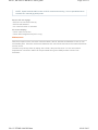
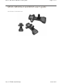
MCU1, MCUlite-2 and MCU5 user's guide
Page 1 of 31
MCU1, MCUlite‐2 and MCU5 user's guide Part Number H-1000-5067-08-A
file://C:\TEMP\~hhC0D2.htm
02/01/2013
MCU1, MCUlite-2 and MCU5 user's guide
Page 2 of 31
Disclaimer & trademarks This document may not be copied or reproduced in whole or in part, or transferred to any other media
or language, by any means, without the prior written permission of Renishaw.
The publication of material within this document does not imply freedom from the patent rights of
Renishaw plc.
Disclaimer RENISHAW HAS MADE CONSIDERABLE EFFORTS TO ENSURE THE CONTENT OF THIS
DOCUMENT IS CORRECT AT THE DATE OF PUBLICATION BUT MAKES NO WARRANTIES OR
REPRESENTATIONS REGARDING THE CONTENT. RENISHAW EXCLUDES LIABILITY,
HOWSOEVER ARISING, FOR ANY INACCURACIES IN THIS DOCUMENT.
Trademarks RENISHAW®, REVO and the probe emblem used in the RENISHAW logo are registered trademarks
of Renishaw plc in the UK and other countries.
apply innovation is a trademark of Renishaw plc.
All other brand names and product names used in this document are trade names, service marks,
trademarks, or registered trademarks of their respective owners.
© 2003 - 2011 Renishaw plc. All rights reserved.
Renishaw part no: H-1000-5067-08-A
Issued: 01 2011
file://C:\TEMP\~hhC0D2.htm
02/01/2013
MCU1, MCUlite-2 and MCU5 user's guide
Page 3 of 31
FCC Information to user (47CFR: 2001 part 15.19) This device complies with Part 15 of the FCC rules. Operation is subject to the following conditions:
1. This device may not cause harmful interference.
2. This device must accept any interference received, including interference that may cause
undesired operation.
Information to user (47CFR: 2001 part 15.105) This equipment has been tested and found to comply with the limits for a Class A digital device,
pursuant to Part 15 of the FCC rules. These limits are designed to provide reasonable protection
against harmful interference when the equipment is operated in a commercial environment. This
equipment generates, uses and can radiate radio frequency energy and, if not used in accordance
with this installation guide, may cause harmful interference to radio communications. Operation of this
equipment in a residential area is likely to cause harmful interference, in which case you will be
required to correct the interference at your own expense.
Information to user (47CFR: 2001 part 15.21) The user is cautioned that any changes or modifications, not expressly approved by Renishaw plc or
authorised representative, could void the user’s authority to operate the equipment.
file://C:\TEMP\~hhC0D2.htm
02/01/2013
MCU1, MCUlite-2 and MCU5 user's guide
Page 4 of 31
EC declaration of conformity RENISHAW plc of New Mills, Wotton-under-Edge, Gloucestershire, GL12 8JR, England declares that:
1. We are the manufacturers of the equipment identified by the following particulars:
Equipment type:
Manual control unit
Model:
MCU1 / MCU5
2. The equipment complies with the protection requirements of directive 89/336/EEC as amended.
3. The equipment conforms to the following standards BS EN 61326:1998/
Electrical equipment for measurement
A1:1998/ A2:2001/
Control and laboratory use
A3:2003 EMC requirements
Immunity to annex A - industrial locations.
Emissions to class A (non-domestic) limits.
BS EN 60204-1: 2006
Safety of machinery - electrical equipment of machines Part 1 General Requirements.
The full EC declaration of conformity is held in the Renishaw technical file. A copy is available on
request.
Renishaw plc declare that the product:
Name:
MCUlite-2
Description:
Manual control unit
has been manufactured in conformity with the following standards:
BS EN 61326-1:2006
BS EN 60204-1: 2006
Electrical equipment for measurement,
control and laboratory use
- EMC requirements Part 1: General requirements
Immunity to Table 2 - industrial locations.
Emissions to Class A - industrial locations.
Safety of machinery - electrical equipment of machines Part 1 General Requirements.
and that it complies with the requirements of the following directives:
2004/108/EC
Electromagnetic compatibility (EMC)
2006/95/EC
Low voltage
file://C:\TEMP\~hhC0D2.htm
02/01/2013
MCU1, MCUlite-2 and MCU5 user's guide
Page 5 of 31
The above information is summarised from the full EC Declaration of Conformity. A copy is available
from Renishaw on request.
file://C:\TEMP\~hhC0D2.htm
02/01/2013
MCU1, MCUlite-2 and MCU5 user's guide
Page 6 of 31
Care & warranty Care of equipment Renishaw probes and associated systems are precision tools used for obtaining precise
measurements and must therefore be treated with care.
Changes to Renishaw products Renishaw reserves the right to improve, change or modify its hardware or software without incurring
any obligations to make changes to Renishaw equipment previously sold.
Warranty Renishaw plc warrants its equipment for a limited period (as set out in our standard terms and
conditions of sale) provided that it is installed exactly as defined in associated Renishaw
documentation.
Prior consent must be obtained from Renishaw if non-Renishaw equipment (e.g. interfaces and/or
cabling) is to be used or substituted. Failure to comply with this will invalidate the Renishaw warranty.
Claims under warranty must be made from authorised service centres only, which may be advised by
the supplier or distributor.
file://C:\TEMP\~hhC0D2.htm
02/01/2013
MCU1, MCUlite-2 and MCU5 user's guide
Page 7 of 31
References & associated documents It is recommended that the following documentation be referred to when installing an MCU.
Renishaw documents Document number Title
H-1000-5223 UCC2 installation guide
H-1000-5109 UCClite-2 installation guide
H-1000-5198 UCCFusion installation guide
External documents
National and international standards including the following may be applicable to the finished machine
or installation:
BS EN ISO 12100:2003 parts 1 and 2 Safety of Machinery - Basic Concepts, General Principles for
Design.
BS EN 60204-1:2006 Safety of machinery - Electrical equipment of machines - Part 1: General
requirements.
file://C:\TEMP\~hhC0D2.htm
02/01/2013
MCU1, MCUlite-2 and MCU5 user's guide
Page 8 of 31
Safety Environmental requirements Indoor use
IP40
Altitude
up to 2000 m
Operating
temperature
+10 °C to +40 °C
Storage temperature -25 °C to +70 °C
Relative humidity
Relative humidity 80% maximum (non-condensing) for temperatures up to
+31 °C.
Linear decrease to 50% at +40 °C
Pollution degree
Pollution degree 2
NOTE: For safety reasons it is recommended that the optional joystick docking station is
mounted outside of the working area of the CMM.
file://C:\TEMP\~hhC0D2.htm
02/01/2013
MCU1, MCUlite-2 and MCU5 user's guide
Page 9 of 31
Manual control systems description NOTE: Unless otherwise specified, all information supplied in this guide applies to the MCU1,
MCUlite-2 and the MCU5.
MCU1 The manual control unit (MCU1) is a comprehensive CMM joystick controller designed for use with
Renishaw’s universal CMM controller range. Including the functionality of both the Renishaw
standard UCC joystick interface and Renishaw PHC10 hand control unit (HCU1), the MCU1 connects
to the UCC controllers as shown.
MCUlite‐2 The MCUlite-2 is a basic low cost joystick . It has the controls necessary to control a 3-axis touchtrigger CMM but without the sophistication of a LCD display screen.
NOTE: The MCUlite-2 is not compatible with UCC1.
MCU5 The MCU5 is a derivative of the MCU1 joystick, the only difference being the addition of a STOP
switch on the membrane keypad.
The MCU5 has been developed for use with Renishaw’s REVO dynamic measuring head and probe
system, where the STOP switch is provided to augment the ESTOP switch. The ESTOP switch has
to cut the motor power to all the axes, including the two REVO axes. This is not always appropriate
as the REVO A axis will drop to 0° by gravity. Operation of the STOP switch will bring the CMM to a
fast stop but the motors will remain engaged in the ‘hold’ state.
file://C:\TEMP\~hhC0D2.htm
02/01/2013
MCU1, MCUlite-2 and MCU5 user's guide
Page 10 of 31
NOTE: The MCU5 is not compatible with UCC1.
file://C:\TEMP\~hhC0D2.htm
02/01/2013
MCU1, MCUlite-2 and MCU5 user's guide
Page 11 of 31
MCU1 features 1
LCD screen
11 Start/stop program button
2
Emergency stop
12 Mode change button
3
Speed override
13 Joystick orientation button
4
Probe disabled LED (red)
14 Axis systems select button
file://C:\TEMP\~hhC0D2.htm
02/01/2013
MCU1, MCUlite-2 and MCU5 user's guide
Page 12 of 31
5
MCU enabled LED (green)
15 F1 function button
6
Joystick enable button
16 F2 function button
7
3-axis joystick with push button
17 Take point/cancel last point button
8
Joystick locks (three separate buttons)
18 F3 function button
9
Probe disable button
19 F4 function button
10
Servo engage button
file://C:\TEMP\~hhC0D2.htm
02/01/2013
MCU1, MCUlite-2 and MCU5 user's guide
Page 13 of 31
MCUlite‐2 features file://C:\TEMP\~hhC0D2.htm
02/01/2013
MCU1, MCUlite-2 and MCU5 user's guide
Page 14 of 31
1
Probe disabled LED (red)
8
Joystick locks (three separate buttons)
2
MCU status LED (tri-colour)
9
Probe disable button
3
Emergency stop
10
Servo engage button
4
Speed override
11
Take point/cancel last point button
5
Slow speed enable buttons
12
F1 function button
6
Fast speed enable buttons
13
F2 function button
7
3-axis joystick
file://C:\TEMP\~hhC0D2.htm
02/01/2013
MCU1, MCUlite-2 and MCU5 user's guide
Page 15 of 31
MCU5 features 1
LCD screen
11 Start/stop program button
2
Emergency stop
12 Mode change button
3
Speed override
13 Joystick orientation button
file://C:\TEMP\~hhC0D2.htm
02/01/2013
MCU1, MCUlite-2 and MCU5 user's guide
Page 16 of 31
4
Probe disabled LED (red)
14 Axis system select button
5
MCU enabled LED (green)
15 F1 function button
6
Joystick enable button
16 F2 function button
7
3-axis joystick with push button
17 STOP switch
8
Joystick locks (three separate buttons)
18 F3 function button
9
Probe disable button
19 F4 function button
10 Servo engage button
file://C:\TEMP\~hhC0D2.htm
20 Take point/cancel last point button
02/01/2013
MCU1, MCUlite-2 and MCU5 user's guide
Page 17 of 31
System operation In normal operation the application software will put the CMM in manual mode, joystick enabled,
except when an automatic DCC program is running.
LCD (Not applicable for MCUlite‐2) This LCD screen is context sensitive to the mode and operation of the MCU. Please refer to the
relevant operational mode section for further details.
Emergency stop The motors are disengaged when the emergency stop switch is operated, any motorised head motion
will also be stopped.
Speed override Controls the machine speed when the CMM is running a program under DCC mode. It will also
control the speed of the REVO head if fitted. The LCD screen displays a percentage value of the
programmed move speed when in DCC operation as shown below. If the speed override is set to less
than 10%, the speed percentage shown on the LCD display will flash.
For MCUlite-2 the indication for the speed override being set below 10% is a flashing ‘MCU enabled’
LED.
Probe disabled LED Indicates the status of the touch probe signal.
LED off - Normal operational mode.
LED lit (red) - Probe disabled.
MCU enabled LED Indicates the operational status of the MCU. For the MCU1 and MCU5 this LED has two states.
LED off - MCU not enabled.
LED lit (green) - MCU enabled.
NOTE: The LED is not illuminated until the joystick is live, so if the setting of the ‘Joystick
file://C:\TEMP\~hhC0D2.htm
02/01/2013
MCU1, MCUlite-2 and MCU5 user's guide
Page 18 of 31
enable’ function is that this button has to be operated the LED will not illuminate until this is
done.
For the MCUlite-2 this LED has 5 states as described below:
LED off - System not switched on or MCUlite-2 not connected
LED lit (red) - System in automatic mode (joystick not enabled)
LED lit (amber) - System in manual mode but joystick not enabled
LED lit (green) - Joystick enabled
LED lit (red flashing) - Speed override set below 10% in automatic mode.
If both the ‘MCU enabled’ LED and ‘Probe disabled’ LED are flashing (‘MCU enabled’ LED flashing
between red and green, ‘Probe disabled’ LED flashing red on/off) this indicates there is a scale failure
on one of the CMM axes.
Joystick enable button On the MCU1 and MCU5 the ‘Joystick enable’ is a single button. On MCUlite-2 there are 4 buttons,
to enable ‘Slow’ speed on each side (left and right handed use) and to enable ‘Fast’ speed on each
side as well.
The ‘Joystick enable’ button is intended to be used as a ‘deadman’s handle’, preventing the
accidental movement of the machine. If enabled, two actions are required to initiate CMM motion:
press ‘Joystick enable’ button and operate the joystick.
Joystick and associated button function All three axis movements are controlled from the one joystick. Moving the joystick left, right,
backwards and forwards controls the CMM X and Y movements. The Z axis is controlled by twisting
the joystick clockwise and anti-clockwise (configurable) *.
If a trigger event occurs during joystick operation, the CMM will stop and back away from the surface
along the vector that it was travelling. After the back off operation, it is necessary for the joystick to
return to its null position for a set period of time before the joystick will permit movement of the CMM.
The default value is 0.05 seconds *. The back-off speeds and distances are defined by the UCC
configuration settings *.
When in head mode, operation of the joystick can move the axis of the head. Pushing the joystick
forwards and backwards will operate the A axis and twisting the joystick will operate the B axis.
For the MCU1 and MCU5, when in rotary table mode, the W axis of the table is controlled by the
twisting of the joystick.
* These values and configuration settings will have been set by your CMM service provider.
Joystick axis locks buttons Permit the locking of one or more axes of the CMM, ignoring any joystick deflections for that axis.
On each of the axis lock buttons there is a LED indicator that will light red when the respective axis is
locked, on the MCU1 and MCU5 there will also be a padlock symbol next to the respective axis, see
file://C:\TEMP\~hhC0D2.htm
02/01/2013
MCU1, MCUlite-2 and MCU5 user's guide
Page 19 of 31
figure below. These buttons toggle on or off.
NOTE: If an axis lock is released when the joystick is deflected, that axis is immediately free to
move.
NOTE: On the MCU1 and MCU5 the axis locks will be transposed when operation of the
CMM joystick orientation function of the joystick is operated.
When the MCUlite-2, MCU1 or MCU5 are in head mode, the axis locks are applied to the comparable
head axes.
On the MCU5 only, when the joystick is in head mode and a REVO head is fitted, the left / right axis
lock button is used to initialise / cancel ‘SNAP ON’. ‘SNAP ON’ is the ability to move the head to the
nearest multiple of a defined head angle. These axis locks will only be active during manual (MCU)
controlled CMM movements. When the CMM is under DCC operation, all axis locks will be released
and be re-latched when returning to manual operation.
Probe disable button Gives the CMM user the ability to move the CMM while the probe is triggered or disconnected by
disabling the probe trigger signal.
WARNING: When operating in this mode the probe is disabled and therefore probe contact with
a surface will NOT stop the CMM. No measured data will be returned to the CMM host
computer.
The ‘Probe disable’ function will only work while in manual mode and cannot be applied while in DCC.
Press and hold the ‘Joystick enable’ button and then press the ‘Probe disable’ button. The CMM can
now be moved irrespective of the probe trigger status. Releasing the ‘Joystick enable’ button cancels
the ‘Probe disable’ function. In all modes the application of ‘Probe disable’ is confirmed by the red
‘Probe disabled’ LED being illuminated.
‘Engage’ button The engage button gives the CMM user the ability to engage or disengage the servos whilst the CMM
is in manual mode.
This button is configured as a toggle switch and has an associated LED to indicate the servo status.
The LED (located within the button) identifies the various operational states and these are as listed
below. On the MCU1 and MCU5 a symbol at the top of the LCD screen (next to the direction arrow)
also indicates whether the servos are engaged.
file://C:\TEMP\~hhC0D2.htm
02/01/2013
MCU1, MCUlite-2 and MCU5 user's guide
Page 20 of 31
CMM servos are disengaged (MCU1 and MCU5 only) LED off – The CMM servos are disengaged.
CMM servos engaging LED amber – The servos are in the process of engaging.
CMM servos engaged (MCU1 and MCU5 only) LED red – The servos are engaged but the joystick is not enabled.
CMM servos engaged and movement is demanded (MCU1 and MCU5 only) LED green – The servos are engaged and the joystick is enabled and ready.
REVO damped mode file://C:\TEMP\~hhC0D2.htm
02/01/2013
MCU1, MCUlite-2 and MCU5 user's guide
Page 21 of 31
LED amber flashing - CMM servos are engaged but REVO head in damped mode.
When REVO or PH20 are fitted, operating the engage switch to disengage the drives puts the REVO
or PH20 into heavily damped mode where it will slowly droop due to gravity. The CMM axes will
disengage as normal..
Program button (MCU1 and MCU5 only) This button can be used to request the application software to start or stop a DCC program by a
system integrator. The button only gives an event to the application software and is not a state button.
NOTE: It is the system integrator’s responsibility to ensure adequate precautions are taken if
this switch is utilised. If it is considered dangerous for the operator to be in the machine working
volume when the DCC program is started, then a second confirmation switch operation is
required (possibly one of the function switches) or this switch should not be enabled at all.
If the button is used to start a program (enter auto mode), the LCD screen will display ‘AUTO’, the
speed, the controller status and an optional text line from the OEM whilst the program is running.
If the button is used to stop a program (enter manual mode) the MCU returns to the previous mode
selected before going into DCC. The LCD screen will then display the normal features for that mode.
Modes of operation (MCU1 and MCU5 only) There are six possible MCU operational modes in addition to the DCC auto mode.
Pressing the ‘MODE’ button on the MCU keypad changes the MCU operational mode, the current
mode is indicated in the top left of the LCD.
NOTE: The modes available to the user of the MCU are configurable. If the mode is not
required it can be switched off.
CMM manual mode Default on start-up.
In manual mode the LCD display will show the tip position of the stylus in the current part co-ordinate
system, in either metric or imperial measurements.
file://C:\TEMP\~hhC0D2.htm
02/01/2013
MCU1, MCUlite-2 and MCU5 user's guide
Page 22 of 31
NOTE: When the MCUlite-2 is in this mode the MCU status LED is amber and changes to
green when a ‘Joystick enable’ button is pressed.
CMM auto mode (MCU1 and MCU5 only) This mode is not selectable via the ‘MODE’ button, but is automatically invoked whenever the UCC is
placed into ‘DCC mode’ (automatic mode).
NOTE: DCC mode is indicated on the LCD (refer to section 4.3). For the MCUlite-2 it is
indicated by the MCU status LED being RED.
Head mode Provides the user with control over the Renishaw PH10, PH20 or REVO heads.
In this mode the joystick will move either of the motorised head axis. The LCD display will indicate the
angle of the two-head rotation axis. For the PH10 the joystick fast/slow button will give jog operation if
not pressed or fast sweep operation if pressed. For the REVO the fast / slow button will control the
speed. If no head is fitted then the LCD screen will display ‘None’.
NOTE: However, to ensure correct operation, the head type must be set correctly within the
configuration.ini file.
With the REVO or PH20 head there is an additional facility of ‘SNAP ON’. The use of ‘SNAP ON’ is
controlled by the use of the left / right axis lock button, repeated pressing will toggle the facility on and
off. ‘SNAP ON’ is displayed in text on the LCD display when it is selected. When ‘SNAP ON’ is
selected the up / down and twist operation of the joystick will move the REVO or PH20 ‘A’ and ‘B’
axes normally, but after about 1 second of the joystick being returned to its null position the head will
automatically move to the nearest multiple of the snap angle.
The snap angle is configurable via the configuration file. The maximum snap angle is 7.5° and the
minimum is 0.05°.
Rotary table mode (MCU1 and MCU5 only) This mode provides the user with control over a rotary table if it is connected to the system. Twisting
the joystick will cause rotary table movement. The joystick fast/slow button will control fast (pressed)
or slow (not pressed) operation. The LCD display will indicate its angle of rotation.
file://C:\TEMP\~hhC0D2.htm
02/01/2013
MCU1, MCUlite-2 and MCU5 user's guide
Page 23 of 31
Sticky button mode (MCU1 and MCU5 only) The purpose of ‘Sticky button mode’ is to allow the user to alternate between two MCU modes without
having to scroll through all of the enabled MCU modes. This feature could be useful when generating
a part program using the application software ‘teach’ utility, where alternating between CMM and
head moves is often required.
If the use of ‘Sticky button mode’ has been enabled by your CMM service provider, you will notice that
when a MCU mode is selected, the title (e.g. CMM Manual, Head Mode, etc), will be highlighted by
displaying it in reverse video (see following example). The highlighted mode title will persist for the
time set in the ‘Sticky Button Time Delay’ parameter.
If you want to toggle between two specific modes, this can set by using the following procedure :a) Using the MCU mode switch, select one of the desired modes, then wait until the mode title returns
to a normal video display.
b) Next select the other desired mode and again wait for its mode title to return to normal video.
c) The sticky buttons are now set. The next time you press the MCU mode button you will return to
the original selected mode and, provided you do not press the MCU mode button before the title has
returned to normal video, the next button press will return you to the other selected mode, and so on.
Sticky button mode is not permanent, you can still access the other modes. If the MCU mode button is
pressed before the previous mode title has returned to normal video, then the mode becomes unstuck
and all the MCU modes can be scrolled through.
Joystick orientation (MCU1 and MCU5 only) file://C:\TEMP\~hhC0D2.htm
02/01/2013
MCU1, MCUlite-2 and MCU5 user's guide
Page 24 of 31
The joystick orientation button changes the relative deflection of the joystick to be transposed to the
actual axis of the CMM. This allows the user to move freely around any side of the CMM and
transpose the joystick orientation such that the machine X and Y axis correspond to joystick direction
of deflection. If any axis lock is asserted and the joystick orientation is changed then the relative axis
lock will be transposed also.
An arrow in the top right of the LCD indicates the orientation of the MCU, see figure below, and
pressing the joystick orientation button will enable the user to scroll through the four operational
positions. The direction of the arrow is to indicate the +Y axis direction of the machine when the
machine co-ordinate system is in force.
NOTE: 1. When switching the system to CMM auto mode, the joystick orientation feature will
drop out and then be re-asserted when the system is placed into CMM manual mode.
2. MCUlite-2 does not have an orientation switch but the default orientation of the joystick can
be preset by your CMM service provider.
Axis select button (MCU1 and MCU5 only) The axis select button changes the CMM motion in any one of three different axis systems.
Machine axis (green LED) In this axis system, the joystick directly controls the machine axes, i.e. a
forward deflection of the joystick produces a pure Y+ movement of the CMM. This is the default
machine setting when the machine is initialised.
Part axis (red LED) In this axis system, the joystick controls the machine axes in the current part axis
system. i.e. a forward deflection of the joystick produces a movement in the part Y+ direction. This
could be a compound of 2 or 3 machine axes.
Stylus axis (amber LED) In this axis system, the joystick controls the machine axes in the axis system
of the selected stylus. i.e. a twist (Z) deflection of the joystick produces a movement along the axis of
the probe stylus. This could be a compound of 2 or 3 machine axes. The stylus axis is a secondary
part coordinate system, applicable only to the MCU joystick, and this needs to be updated by the
file://C:\TEMP\~hhC0D2.htm
02/01/2013
MCU1, MCUlite-2 and MCU5 user's guide
Page 25 of 31
application software to reflect the active stylus axis.
The axis system in which the MCU is moving the CMM is indicated on the LCD by indicating the axis
system that is active by a M, P or S, and by a tri-colour LED mounted below the axis select button.
Pressing the axis select button will enable the user to scroll through the 3-axis systems.
To change to the required axis system the ‘axis select’ button must be pressed and held on the
desired axis system. This selection is confirmed by pressing the ‘Joystick enable’ switch. Both
switches can then be released. This complex change procedure prevents unintentional changing of
the axis system which could give unexpected machine movement.
Take point/cancel point This button is designed to allow the user to record or cancel chosen machine positions.
When a program is being generated by the ‘teach and learn’ method, the user will use the take point
button to permit the CMM to record a waypoint and use it in the program. When using the cancel point
button it will indicate to the application software that the point just taken (either a touch point or a
position generated by the take point button) should be removed from the program.
The cancelling process can be repeated many times and the front-end program will use it to delete
multiple stored points.
NOTE: When the take point button is pressed, the machine’s XYZ position will be recorded and
a waypoint is created. However, if the MCU1 or MCU5 are in ‘Rotary Head’ or ‘Table’ mode, it
only records the relevant index position.
Function buttons The application software can define the F1 to F4 function buttons (on MCUlite only F1 and F2 are
available). Their status can be read at any time and in any mode. These buttons have no effect on
the UCC controller as they are solely for the use of the front-end software. The associated keypad
LEDs can also be switched on and off at any time.
An example of use is that one of the buttons may be used to initiate a circle measurement command
when the system is in a manual mode and being used for teach and learn programming. Another
may be used for a plane measurement etc.
STOP button (MCU5 only) The STOP button only operates when the CMM is in automatic (DCC) mode. It gives the operator the
ability to rapidly stop the CMM and REVO head without disengaging. When the CMM has stopped
the system stays in hold state with both the CMM and REVO head engaged. For a REVO system the
STOP system is a better way of stopping the system than emergency stop. The emergency stop
works by removing power from all motors which causes the REVO probe to drop due to gravity.
file://C:\TEMP\~hhC0D2.htm
02/01/2013
MCU1, MCUlite-2 and MCU5 user's guide
Page 26 of 31
Installation Part numbers There are three MCU joysticks available:
• A-1333-0007 - MCU1
• A-5121-0003 - MCU5
• A-5331-0015 - MCUlite-2
Each of these kit are provided with a 5 metre flexible joystick cable. Replacement or longer cables
are available from your machine supplier or directly from Renishaw.
• A-1016-8098 - 5 m cable
• A-1016-8099 - 10 m cable
• A-1016-8100 - 20 m cable
Connecting the MCU to the UCC controller The MCU joystick kits include a 5 metre flexible cable provided as standard. The cable is fitted from 9
pin D connector on the rear of MCU to a 9 pin D connector on the rear of the UCC controller.
Connecting to the UCC2 Connecting to the UCClite‐2 file://C:\TEMP\~hhC0D2.htm
02/01/2013
MCU1, MCUlite-2 and MCU5 user's guide
Page 27 of 31
Connecting to the UCCFusion The emergency stop button on the MCU1, MCUlite-2 or MCU5 has a dedicated circuit that is fed
directly into the rear of the UCC2. These connectors are then integrated to the CMMs emergency
stop system in the SPA2-2, SPAlite or Fusion. If non-Renishaw servo power amplifiers are used then
it is the integrators responsibility to connect the MCU E-stop switch into the emergency stop system.
System configuration Joystick configuration
There are various configuration settings that have to made to ensure the MCU joystick functions to
the operators requirements. These settings must be made when setting up the UCC controller using
the UCCassist-2 Commissioning software. They are described in the following table.
Machine description section Parameter Default value Comment
Parameter
Default Comment
value
JoystickMaxFastSpeed
100
mm/s
file://C:\TEMP\~hhC0D2.htm
This value is the target speed for full joystick deflection
with the joystick fast button operated.
02/01/2013
MCU1, MCUlite-2 and MCU5 user's guide
Page 28 of 31
JoystickMaxFastAcceleration
500
mm/s2
This is the maximum acceleration and deceleration value
used when operating the joystick in fast mode.
JoystickMaxTouchSpeed
30 mm/s This value is the target speed for full joystick deflection in
measure mode (without the joystick fast button operated).
JoystickMaxTouchAcceleration 30
mm/s2
This is the maximum acceleration and deceleration value
used when operating the joystick in measure mode.
StandardBeepTime
0.2 s
This controls the time the MCU buzzer operates for a
probe trigger event, it can be set to zero if the buzzer is
not required.
ZAxisDirection
N/A
The standard configuration is for a clockwise rotation of
the joystick to cause –Z motion. This can be inverted if
required.
InitialMCUOrientation
N/A
This parameter sets the initial orientation of the MCU, the
default setting is that forward movement of the joystick
will cause +Y motion of a YXZ configured machine.
EnableButtonDelay
N/A
This setting enables the use of the “Joystick Enable”
button, the default setting is enabled, if its use is not
enabled then the joystick will always be live when the
machine is in manual mode (Not Recommended)
EnableButtonOperation
N/A
If the use of the “Joystick Enable” button is enabled this
parameter sets the time after the button has been
operated that the joystick is enabled for. The default
setting is 0, i.e. the button has to be depressed to allow
motion.
NumberOfMCUModes
5
This setting controls the number of MCU modes that can
be accessed.
ModesSequence
N/A
These settings control the mode types and the sequence
in which they are displayed.
NullWaitTime
0.05 s
If a limit switch or surface is encountered when under
joystick control the system will switch to automatic mode
for the backoff, the null wait time sets the time the joystick
has to be in its null position after the backoff has finished
before joystick movement is permitted.
EnableJoystickSpeedOverride N/A
The speed override control is normally enabled when the
machine is in DCC mode, this can be disabled using this
control.
RemeasureMode
N/A
This parameter switches on and off remeasure mode.
The default setting is off.
StickyButtonTimeDelay
0s
This parameter sets the sticky button time delay (see
section 2.12.6) The default setting is 0 (off).
NOTE: The Joystick assembly has deadbands. In joystick mode the frist 11% of mechanical
movement does not produce motion and full speed is reached at 91%. These deadbands are
file://C:\TEMP\~hhC0D2.htm
02/01/2013
MCU1, MCUlite-2 and MCU5 user's guide
Page 29 of 31
necessary to accomodate electro-mechanical tolerences in the joystick assembly, these settings
are not user configurable.
Fault finding Examining the MCU LCD display, status LED’s, the system configuration and current conditions, can
solve many problems.
NOTE: As with most cable connected ancillary equipment, it is the actual cable that is the most
vulnerable part, particularly with a joystick where it can be trapped by the part under inspection,
pulled if caught by machine motion, trodden on, run over, etc. If any malfunction with the MCU
occurs, the first step should be an examination of the cable.
Suspect operation of joystick or buttons
There is a comprehensive test program for the MCU joystick operation and button function within
UCCassist-2. Plese refer to the UCCassist-2 user’s guide (Renishaw part number H-1000-5224) for
details.
The joystick will not move the CMM
Several conditions have to be satisfied before joystick controlled moves can be made:
• The is connected to the UCC should have been set up in the configuration file.
• The joystick should be 'enabled'.
• The MCU ‘joystick enable’ button must be pushed.
• The axis locks must not be applied.
• The CMM application software must be in manual (joystick) mode..
• The probe must not be ‘deflected’, unless probe override is on.
• No limit switches should be open, unless disabled.
• The CMM position must be inside all ‘soft limits’ if these are enabled.
The speeds are too low or too high
• Check the joystick speeds and accelerations that are set in the UCC configuration file, are correct.
• Check the operation of the fast/slow switch. Higher speeds will be obtained when this switch is
active.
The motors disengage during joystick operation
• If the joystick max speed is set to a high value, the machine may be able to exceed the maximum
move speed to cause an overspeed error.
• If the joystick max fast acceleration is set to too high a value, the motor signals may attempt to
exceed the overdrive limits and cause an overdrive fault.
• If the system proportional gains are set too high, or the velocity gains are too low, an overdrive fault
may occur.
Speed override does not work correctly
• This feature must be enabled separately from the general joystick enabling: it is an entry in the UCC
configuration file.
file://C:\TEMP\~hhC0D2.htm
02/01/2013
MCU1, MCUlite-2 and MCU5 user's guide
Page 30 of 31
NOTE: Speed override ONLY works on DCC moves and scanning. It is not operational when
the MCU is in manual (joystick) mode.
Servos will not engage
• ESTOP not connected correctly
• ESTOP still asserted
• An outer limit switch is activated
No screen display
• Check cable connection
• Check MCU daughtercard (UCC1 only)
Maintenance With the exception of the connection cable the MCU1, MCU5, MCUlite and MCUlite-2 have no user
serviceable parts. Should a unit become defective then it should be returned to the nearest Renishaw
service centre.
The MCU may be kept clean by wiping with a clean, damp lint-free cloth. Do not use solvents.
Replacement connection cables can be purchased through the CMM provider or direct from
Renishaw:
file://C:\TEMP\~hhC0D2.htm
02/01/2013
MCU1, MCUlite-2 and MCU5 user's guide
file://C:\TEMP\~hhC0D2.htm
Page 31 of 31
02/01/2013