1
IS20008696
CAGE No. 79272
20 November 1998
(Preliminary)
Direct Access System User’s Guide
for the EOS–AM Spacecraft
(ICD–107)
Prepared under:
Contract NAS5–32500
NASA Goddard Space Flight Center
Greenbelt, Maryland 20771
Prepared by:
Lockheed Martin Corporation
Lockheed Martin Missiles & Space
Valley Forge Operations
P.O. Box 8555
Philadelphia, PA 19101
DMC112098
Sheet 1 of 55
IS20008696
20 November 1998
(This page intentionally left blank.)
DMC201198
2
IS20008696
20 November 1998
REVISION LOG
This log identifies those portions of this document which have been revised since the original
issue. Revised portions of each page, for the current revision only, are identified by marginal
striping.
Revision
Paragraph Number(s) Affected
Rev. Date
Preliminary 1
Feb. 28 1997
Preliminary 2
Nov. 20 1998
3
Approval
DMC201198
IS20008696
20 November 1998
(This page intentionally left blank.)
DMC201198
4
IS20008696
20 November 1998
TABLE OF CONTENTS
SECTION /
PARAGRAPH
TITLE
PAGE
1
SCOPE . . . . . . . . . . . . . . . . . . . . . . . . . . . . . . . . . . . . . . . . . . . . . . . . . . . . . .
9
2
APPLICABLE DOCUMENTS . . . . . . . . . . . . . . . . . . . . . . . . . . . . . . . . . . .
11
2.1
Lockheed Martin Documents . . . . . . . . . . . . . . . . . . . . . . . . . . . . . . . . . . .
11
2.2
NASA Documents . . . . . . . . . . . . . . . . . . . . . . . . . . . . . . . . . . . . . . . . . . . .
12
OVERVIEW OF THE DIRECT ACCESS SYSTEM (DAS) . . . . . . . . . . . .
13
3.1
DAS RF Communication Links . . . . . . . . . . . . . . . . . . . . . . . . . . . . . . . . .
13
3.2
DAS Functional Description . . . . . . . . . . . . . . . . . . . . . . . . . . . . . . . . . . . .
14
3.3
DAS–to–Earth Station Communication Link Interface Description . . . . . .
14
3.4
Baseband Signal Characteristics . . . . . . . . . . . . . . . . . . . . . . . . . . . . . . . . .
23
3.4.1
Convolutional Coding . . . . . . . . . . . . . . . . . . . . . . . . . . . . . . . . . . . . . . .
23
3.4.2
Viterbi Decoding . . . . . . . . . . . . . . . . . . . . . . . . . . . . . . . . . . . . . . . . . . .
23
DAS Management . . . . . . . . . . . . . . . . . . . . . . . . . . . . . . . . . . . . . . . . . . . .
29
3.5.1
Scheduling . . . . . . . . . . . . . . . . . . . . . . . . . . . . . . . . . . . . . . . . . . . . . . . .
29
3.5.2
Anomalies . . . . . . . . . . . . . . . . . . . . . . . . . . . . . . . . . . . . . . . . . . . . . . . . .
29
DAS SUBSYSTEM OPERATING MODES . . . . . . . . . . . . . . . . . . . . . . . . .
31
4.1
Pseudo–Random Bit Stream Test . . . . . . . . . . . . . . . . . . . . . . . . . . . . . . . .
31
4.2
Direct Broadcast of MODIS Instrument Data . . . . . . . . . . . . . . . . . . . . . . .
31
4.3
Direct Downlink of ASTER Instrument Data . . . . . . . . . . . . . . . . . . . . . . .
32
4.4
Direct Playback of Recorded Science and Housekeeping Data . . . . . . . . .
33
4.5
Standby . . . . . . . . . . . . . . . . . . . . . . . . . . . . . . . . . . . . . . . . . . . . . . . . . . . .
33
5
DAS RF CHARACTERISTICS . . . . . . . . . . . . . . . . . . . . . . . . . . . . . . . . . . .
35
6
DAS COMMUNICATION LINK BUDGETS . . . . . . . . . . . . . . . . . . . . . . . .
39
6.1
Direct Broadcast (DB) Link Budget . . . . . . . . . . . . . . . . . . . . . . . . . . . . . .
39
6.2
Direct Downlink (DDL) Link Budget . . . . . . . . . . . . . . . . . . . . . . . . . . . . .
39
6.3
Direct Playback Link Budgets . . . . . . . . . . . . . . . . . . . . . . . . . . . . . . . . . . .
40
3
3.5
4
5
DMC201198
IS20008696
20 November 1998
TABLE OF CONTENTS (Continued)
SECTION /
PARAGRAPH
TITLE
PAGE
APPENDIX I
1
ANTENNA PERFORMANCE DATA . . . . . . . . . . . . . . . . . . . . . . . . . . . . . .
45
APPENDIX II
2
IMPACT OF DATA CODING ON REQUIRED EB/NO AND
BIT ERROR RATE . . . . . . . . . . . . . . . . . . . . . . . . . . . . . . . . . . . . . . . . . . . .
49
APPENDIX III
3
DMC201198
ACRONYM LIST . . . . . . . . . . . . . . . . . . . . . . . . . . . . . . . . . . . . . . . . . . . . .
6
51
IS20008696
20 November 1998
LIST OF FIGURES
FIGURE
TITLE
PAGE
1
X–band Block Diagram . . . . . . . . . . . . . . . . . . . . . . . . . . . . . . . . . . . . .
15
2
DAS Antenna Configuration . . . . . . . . . . . . . . . . . . . . . . . . . . . . . . . . .
16
3
DAS Satellite–to–Earth Station Geometry . . . . . . . . . . . . . . . . . . . . . .
18
4
EOS–AM DAS Digital Satellite Communications Link Model . . . . . .
19
5
Spacecraft–to–User Downlink Configuration for DAS Direct Broadcast
Mode with Q:I=4:1 . . . . . . . . . . . . . . . . . . . . . . . . . . . . . . . . . . . . . . . .
20
Spacecraft–to–User Downlink Configuration for DAS Direct Downlink
(DDL) or Direct Playback 2 (DP2) Modes With Q:I=4:1 . . . . . . . . . . .
21
Spacecraft–to–User Downlink Configuration for DAS Direct Playback 1
(DP1) or Pseudo–Random Bit Stream (PRBS) Modes with Q:I=1:1 . .
22
8
Format of Channel Access Data Unit (CADU) with Science Data . . .
24
9
Format of CADU with Fill Data . . . . . . . . . . . . . . . . . . . . . . . . . . . . . .
25
10
PRN GEN . . . . . . . . . . . . . . . . . . . . . . . . . . . . . . . . . . . . . . . . . . . . . . .
26
11
Functional Configuration of the Convolutional Encoder . . . . . . . . . . .
27
12
n–Parallel Data Encoder and the n–Encoded Sequences . . . . . . . . . . .
28
13
DAS System EIRP Minus Axial Ratio Loss . . . . . . . . . . . . . . . . . . . . .
46
14
DAS System Antenna Gain (dBi) Versus Antenna Boresight Angle . .
47
15
DAS System Axial Ratio Versus Ground Antenna Elevation Angle . .
48
16
Theoretical Curves of The Probability of Error, Pe, As A Function of
Data Coding Methods . . . . . . . . . . . . . . . . . . . . . . . . . . . . . . . . . . . . . .
50
6
7
7
DMC201198
IS20008696
20 November 1998
LIST OF TABLES
TABLE
TITLE
PAGE
I
Science Data Downlink Service Allocations . . . . . . . . . . . . . . . . . . . .
13
II
Major Components . . . . . . . . . . . . . . . . . . . . . . . . . . . . . . . . . . . . . . . .
14
III
DAS Subsystem Operating Modes . . . . . . . . . . . . . . . . . . . . . . . . . . . .
32
IV
X–band (DAS) Subsystem Performance Characteristics . . . . . . . . . . .
35
V
DAS Return Link Performance Summary [1] . . . . . . . . . . . . . . . . . . . .
39
VI
DAS Return Downlink Budget for Direct Broadcast (DB) Mode
with Q:I = 4:1 . . . . . . . . . . . . . . . . . . . . . . . . . . . . . . . . . . . . . . . . . . . .
41
DAS Return Downlink Budget for Direct Downlink (DDL) or
Direct Playback 2 (DP2) Modes . . . . . . . . . . . . . . . . . . . . . . . . . . . . . .
42
DAS Return Downlink Budget for Direct Playback 1 (DP1) Mode . . .
43
VII
VIII
DMC201198
8
IS20008696
20 November 1998
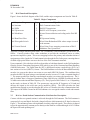
1
SCOPE
This document provides the following:
a. an overview of the types of services which will be provided to the user community by
the EOS–AM Spacecraft Direct Access System (DAS)
b. information which provides the user community an understanding of the ground station
requirements for accessing the DAS services.
9
DMC201198
IS20008696
20 November 1998
(This page intentionally left blank.)
DMC201198
10
IS20008696
20 November 1998
2
APPLICABLE DOCUMENTS
The following documents are listed for the convenience of the user. These documents do not form
a part of this document and are not controlled by their reference herein.
The EOS–AM Spacecraft Communications Subsystem Specification, PS20008580, controls the
requirements for the DAS design and operation. This specification shall govern in the event of a
conflict between this DAS User’s Guide and any of the documents listed below.
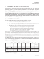
2.1
Lockheed Martin Documents
Design Documents:
20054745
EOS–AM–1 Spacecraft Flight Systems Manual,
Volume III, Communications Subsystem
EOS–DN–COMM–014B
X–band Design Approach
EOS–DN–COMM–021
Design and Breadboard Report for the KSA and DAS
Modulators
EOS–DN–COMM–025
Design and Breadboard Report for the Convolutional
Encoder Boards in the EOS KSA and DAS Modulators
EOS–DN–C&DH–052
Command and Data Handling Subsystem Functional
Description
Specifications:
PS20005396
EOS–AM Spacecraft Contract End Item Specification
(SEP–101)
PS20008506
Critical Item Development Performance Specification:
Direct Access System Antenna
PS20008573
Critical Item Development Performance Specification:
DAS Upconverter
PS20008575
Critical Item Development Specification: Science Data
Formatting Equipment
PS20008580
Performance Specification, Communications
Subsystem for EOS–AM Spacecraft
PS20008589
Critical Item Development Performance Specification:
DAS Modulator
PS20008590
Critical Item Development Performance Specification:
DAS SSPA
11
DMC201198
IS20008696
20 November 1998
2.2
PS20008745
Critical Item Development Performance Specification:
Command and Data Handling/Communications
Equipment Module
IS20008658
Interface Control Document Data Format Control
Book for EOS AM Spacecraft (ICD–106)
Source:
Lockheed Martin Missiles and Space
P.O. Box 8555
Philadelphia, PA 19101–8555
NASA Documents
Design Documents:
Memo to J. Deskevich, GSFC Code 502 from J. Hart,
STel “EOS AM1 Interference to DSN at X–band,”
March 20, 1995.
Specifications:
531–RFICD–EOS AM–1/EPGN X–band Radio Frequency Interface Control Document
(RFICD) Between the EOS–AM–1 Spacecraft and the
EOS Polar Ground Network (EPGN)
Source:
NASA Goddard Space Flight Center
Code 531.1
Greenbelt, MD 20771
CCSDS 101.0–B–2
Jan. 1987
Consulting Consortium of Space Data Systems
Telemetry Channel Coding, Issue 2, Blue Book
Source:
CCSDS Secretariat
Communications and Data Systems Div. (Code–TS)
National Aeronautics and Space Administration
Washington, DC 20546
DMC201198
12
IS20008696
20 November 1998
3
OVERVIEW OF THE DIRECT ACCESS SYSTEM (DAS)
The Direct Access System (DAS) provides real–time science data from the EOS–AM–1 Spacecraft
Instruments directly to the science community independent of the EOS Data and Information
System (EOSDIS). In addition to providing a direct–to–user communications link, the DAS serves
as a backup to the TDRSS Ku–band science data return communications path.
The DAS transmits science data via an 8.2125 GHz link directly to user ground stations on the earth
at the data rates shown in Table III. The DAS return link is a scheduled service which is available
100% of the time during Spacecraft science mode, and the availability of DAS services does not
depend on High Gain Antenna (HGA) operability.
3.1
DAS RF Communication Links
The DAS provides three types of science data return capabilities, including:
a.
real–time direct downlink (DDL) of ASTER instrument data
b. real–time direct broadcast (DB) of MODIS instrument data and Spacecraft ancillary data
c. direct playback (DP) for a backup to the Ku–band science data downlink.
The direct playback service is described here for completeness. The
performance requirements for the DAS contingency direct playback
service are controlled by the X–band Radio Frequency Control
Document (RFICD), 531–RFICD–EOS AM–1/EPGN.
These services are used to downlink data from Spacecraft Instruments as shown in Table I. The
Spacecraft Bus will include packetized ancillary data in the DB and DP data streams which are
identical to the ancillary data included with the science data for transmission via the Ku-band link.
When DP service is used, the C&DH will include Spacecraft housekeeping telemetry in the data sent
to the DAS Modulator.
The DB and DDL services will be provided during normal Spacecraft operations. The DP service
will be used in contingency conditions only, i.e., when the Spacecraft is incapable of normal recorder
playback via the HGA–TDRSS link.
Table I. Science Data Downlink Service Allocations
ASTER CERES
DDL
DB
DP
MISR
MOPITT
MODIS
Ancillary
Data
n
n
n
n
n
n
n
n
n
Housekeeping
Telemetry
n
In addition to these three science data downlinks, the DAS provides a Pseudo–Random Bit Stream
(PRBS) downlink for test purposes.
13
DMC201198
IS20008696
20 November 1998
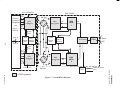
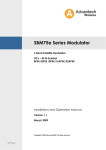
3.2
DAS Functional Description
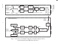
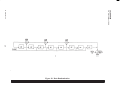
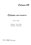
Figure 1 shows the block diagram of the DAS, and the major components are listed in Table II.
Table II. Major Components
Subsystem Component
Qty
Major Function
DAS Antenna
1
DAS Communications Links
DAS SSPA
2
DAS RF Transmission
DAS Upconverter
2
DAS IF to RF Frequency conversion
DAS Modulator
2
Science Data modulation and coding on the DAS RF
link
DAS Band Pass Filter
1
RF Spectrum limiting
DAS Waveguide Switch
1
Select Prime/Redundant SSPA whose output is routed
to the antenna
DAS Coaxial Switch
2
Select Prime/Cross–strapping connections of DAS/
Modulator/ Das Upconverter
The DAS is a single antenna system with 2–for–1 redundancy of the modulators, upconverters, and
SSPAs. Coaxial switches allow either modulator to provide the modulated carrier to either
upconverter/amplifier system. This cross–strapping between the primary and redundant chains of
equipment provides 4 paths for X–band transmission through the DAS subsystem, ensuring that no
credible single point failure can cause the loss of the DAS communication link.
Upon command, 4–bit wide data is delivered on either or both data channels to the DAS modulator
from the Science Formatting Equipment (SFE) which is part of the Command and Data Handling
(C&DH) Subsystem. The signal from the SFE is differential emitter–coupled logic (ECL) in a
non–return to zero level (NRZ–L) format. The DAS Modulator reclocks the data and differentially
encodes it to convert the data to non–return to zero mark (NRZ–M) format. The modulator then
encodes the NRZ–M signal using a convolutional encoder at a rate of 1/2 and a constraint length of
7. The output symbol rate from the convolutional encoder is two times the input bit rate. The I–
and Q–channel data is Staggered Quadrature Phase Shift Keying (SQPSK) modulated onto the
X–band carrier at the intermediate frequency (IF). The Q:I power ratio is either 1:1 or 4:1 depending
on the mode, as shown in Table III. The upconverter converts the IF frequency to X–band and
delivers this signal to the solid state power amplifier (SSPA). The SSPA provides the final
amplification required to provide adequate RF power at X–band to close the communication link.
The output of the SSPA is routed to the DAS antenna via a waveguide transfer switch and transmit
filter.
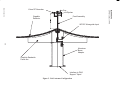
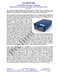
3.3
DAS–to–Earth Station Communication Link Interface Description
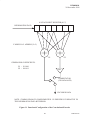
Contact with the user ground stations is achieved through the DAS antenna. The DAS antenna is
composed of a cup and dipole feed with a shaped reflector which transmits in X–band, as shown in
Figure 2. The antenna operates with right hand circularly polarized signals. The reflector is shaped
to provide approximately constant power density on the earth for a subtended angle of ±63.8° about
the Spacecraft earth pointing axis.
DMC201198
14
RECORDER EM
4 MHz
CH–1
DATA
Science
Formatting
Equipment
(SFE)
(Part of
C&DHS)
DAS PANEL
FROM
MO1
LO
4
CLK1
LO
SWITCH
LO
CLK2
CH–2
DATA
RF
DAS
Upconverter
1
DAS
Modulator
1
IF
RF
7.5 V
IF
4
DAS
SSPA
1
EPC 1
EPC 2
Side–A
FDB
Part of
EPS
BDU
Part of
C&DHS
FDB
BDU
Part of
EPS
Part of
C&DHS
RF
W/G Switch
DAS
Filter
RF
X–Band
RHCP
15
Side–B
EPC 1
EPC 2
CH–1
DATA
4
CLK1
CLK2
CH–2
DATA
2
DAS
Modulator
2
LO
LO
IF
4
IF
4 MHz
FROM
MO2
DAS
Upconverter
2
RF
DAS
SSPA
2
RF
7.5 V
IF
SWITCH
DMC201198
Figure 1. X–band Block Diagram
120 V
IS20008696
20 November 1998
– DAS Equipment
CMD/TLM Signals
PRA
Cup
Dipoles
Feed Assembly
Graphite
Reflector
WR112 Waveguide Input
16
Aluminum
Boom
Adapter
Graphite Sandwich
Panel ribs
Interface to DAS
Support Tripod
Figure 2. DAS Antenna Configuration
IS20008696
20 November 1998
DMC201198
Vitron RF Absorber
IS20008696
20 November 1998
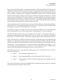
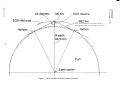
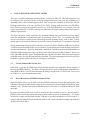
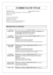
Figure 3 shows the DAS satellite–to–earth station geometry. The boresight of the DAS antenna will
continuously point toward the center of the earth. User ground stations, which are assumed to be
either 3 meter or 11.3 meter receiver dishes, should be programmed to track in X–band as the satellite
passes overhead. The Spacecraft–to–earth station link distance ranges from 2575 km (at a ground
station elevation angle of 5 degrees) to 705 km (at a station elevation angle of 90 degrees). Ground
antenna support is dependent on favorable radio line–of–sight conditions when the ground antenna
angle is greater than 5 degrees (i.e. above the local mask). The ground station location determines
the orbits and portions of orbits in which contacts can be made, and the ground station acquisition
cone determines the duration of the contact for the given orbit.
The ground antenna will be selected by the user to provide the performance needed for satisfactory
link performance. The ground antenna which meets the user’s requirements may be different from
the antennas assumed in the link budget tables in Section 6.
Note that 3 meter dishes are suitable only for the lower data rates of DB service, not for the high data
rates of DDL and DP service which require dishes of approximately 11.3 meters diameter.
The DAS transmits all data at the fixed frequency of 8.2125 GHz. The frequency reference is
generated by an Ovenized Crystal Oscillator (OCXO). The center carrier frequency derived from
the OCXO is 912.5 MHz ±300 Hz. The frequency stability of the OCXO are as shown in Table IV.
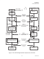
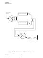
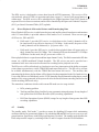
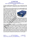
Figure 4 illustrates the overall DAS communications link. Onboard the Spacecraft, instrument data
undergoes a concatenated encoding process in which Reed Solomon coding is applied by the SFE
and then convolutional encoding is applied within the DAS modulator prior to transmission to the
earth station. At the earth station, it is assumed that the demodulator will employ a 3–bit
soft–decision Viterbi decoding process (code rate of 1/2 and constraint length of 7) and that the bit
stream will be Reed Solomon decoded prior to delivery to the data users.
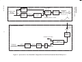
The specific Spacecraft–to–user downlink configurations for the various DAS services are shown
in the following figures:
a. Figure 5 – Direct Broadcast (DB) with Q:I=4:1
b. Figure 6 – Direct Downlink (DDL) or Direct Playback 2 (DP2) with Q:I=4:1
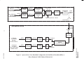
c. Figure 7 – Direct Playback 1 (DP1) or Pseudo–Random Bit Stream (PRBS) Test with
Q:I=1:1
The user is encouraged to review the X–band RFICD for a detailed description of NASA’s approach
to preparing the direct playback data at EPGN.
17
DMC201198
18
Figure 3. DAS Satellite–to–Earth Station Geometry
IS20008696
20 November 1998
DMC201198
Note: the link distance is 2575 Km at the min–
imum ground station elevation angle of 5 degrees.
IS20008696
20 November 1998
11.3M or 3M
Earth Station
8212.5 MHz
SSPA
DAS Antenna
Receiver
DAS
Upconverter
Waveform
Continuous
Channel
QPSK
Modulator
Demodulator
Discrete
Error Coding
Channel
DAS
Modulator
NRZ–M
Rate = 26.25, 150, 210 Msps
(I/Q Channels)
Viterbi
Decoder
Rate 1/2, K=7
Convolutional
Encoder
NRZ–L
Rates = 13.125,
75, 105 Mbps
(I,Q Channels)
NRZ–L
Rate = 13.125, 75, 105 Mbps
(I/Q Channels)
13% Bits/Frame
Overhead
Reed Solomon Encoder
Bits
Added
Data
Storage
Reed–Solomon Decoder
Bits
Subtracted
SFE
Discrete Source
Channel
EOS
Instruments
Users
Figure 4. EOS–AM DAS Digital Satellite Communications Link Model
19
DMC201198
Differential
Encoder
CCSDS CADUs
DB Data
13.125 Mbps
NRZ–L
Differential
Encoder
Power Ratio
Q:I = 4:1
NRZ–M
I Channel
NRZ–M
Q Channel
Convolutional
Encoder
(1)
SQPSK
Modulator
Upconverter
Power
Amplifier
DAS
Antenna
RHC
Frequency Source: OCXO
8212.5 MHz
RHC
Receive
Antenna
USER GROUND STATION
20
Down
Converters
I Channel (not used)
SQPSK
Demodulator / Receiver
Q Channel
13.125 Mbps
CCSDS CADUs
NRZ–L
Differential
Decoder
NRZ–M
Viterbi
Decoder
Bit
Sync
Q Channel
Figure 5. Spacecraft–to–User Downlink Configuration for DAS Direct Broadcast Mode With Q:I=4:1
IS20008696
20 November 1998
DMC201198
SPACECRAFT
NRZ–L
DB Data
13.125 Mbps
CCSDS CADUS
DDL or DP2 Data
105 Mbps
CCSDS CADUS
NRZ–L
Differential
Encoder
Differential
Encoder
NRZ–M
I Channel
NRZ–M
Q Channel
Convolutional
Encoder
(1)
Convolutional
Encoder
(8)
SPACECRAFT
Power Ratio
Q:I = 4:1
SQPSK
Modulator
Upconverter
Power
Amplifier
DAS
Antenna
RHC
Frequency Source: OCXO
8212.5 MHz
RHC
Receive
Antenna
USER GROUND STATION
21
Down
Converters
I Channel
13.125 Mbps
DB data
CCSDS CADUs
NRZ–L
Q Channel
105 Mbps
DDL or DP2 data
CCSDS CADUs
NRZ–L
Differential
Decoder
NRZ–M
Viterbi
Decoder
(1)
Bit
Sync
I Channel
SQPSK
Demodulator / Receiver
Differential
Decoder
NRZ–M
Viterbi
Decoder
(8)
Bit
Sync
Q Channel
IS20008696
20 November 1998
DMC201198
Figure 6. Spacecraft–to–User Downlink Configuration for DAS Direct Downlink (DDL) or
Direct Playback 2 (DP2) Modes With Q:I=4:1
Differential
Encoder
Formatted Science
(DP1) Data
De–Bit–Interleaver
150 Mbps
CCSDS CADUS
PRBS Data
75 Mbps
NRZ–M
I Channel
NRZ–M
Differential
Encoder Q Channel
Convolutional
Encoder
(8)
Convolutional
Encoder
(8)
SPACECRAFT
Power Ratio
Q:I = 1:1
SQPSK
Modulator
Power
Amplifier
Upconverter
Frequency Source: OCXO
NRZ–L
USER GROUND STATION
DAS
Antenna
RHC
8212.5 MHz
RHC
Receive
Antenna
22
Down
Converters
BER Test Set
NRZ–L
DP1 data
150 Mbps
CCSDS CADUS
I Channel
75 Mbps
Bit–Interleaver
NRZ–L
Q Channel
75 Mbps
Differential
Decoder
NRZ–M
Viterbi
Decoder
(8)
Bit
Sync
I Channel
SQPSK
Demodulator / Receiver
Differential
Decoder
NRZ–M
Viterbi
Decoder
(8)
Bit
Sync
Q Channel
BER Test Set
Figure 7. Spacecraft–to–User Downlink Configuration for DAS Direct Playback 1 (DP1) or
Pseudo–Random Bit Stream (PRBS) Modes With Q:I=1:1
IS20008696
20 November 1998
DMC201198
NRZ–L
PRBS Data
75 Mbps
IS20008696
20 November 1998
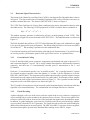
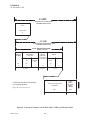
3.4
Baseband Signal Characteristics
The format of the Channel Access Data Units (CADUs) which are the DAS downlink data is shown
in Figure 8. The Spacecraft Science Formatting Equipment (SFE) will use fill data as necessary to
maintain constant data rates. The format of the fill CADU is shown in Figure 9.
The VCDU Data Unit Zone for Science Data is randomized to ensure data transition density in the
downlink stream. The following CCSDS polynomial is XOR’ed with the data to randomize it.
h(x) = x8 + x7 + x5 + x3 + 1
The random sequence generator is initialized to all One’s at the beginning of each VCDU. This
randomizing is applied to science data and to SFE fill VCDU’s. This randomization is as shown in
Figure 10.
The DAS downlink data will have a (255,223) Reed Solomon (RS) outer code with interleave depth
I=4 to provide improved bit error performance. The RS encoding will achieve a bit error rate (BER)
of less than 10–7. RS encoding is performed on the randomized data.
Convolutional encoding and Viterbi decoding with eight levels of quantization (3–bit soft decision)
are used to provide a performance gain for each type of DAS service, as explained below.
3.4.1
Convolutional Coding
For the X–band downlink, a non–systematic, transparent convolutional code with a code rate of 1/2
and a constraint length of 7 is used. The I– and Q–channel data signals are differentially formatted
separately, and then rate–1/2 convolutionally encoded prior to transmission to the I– and
Q–channels.
Each rate 1/2 convolutional encoder is an “n–parallel encoder.” An “n–parallel encoder” consists
of n–branch encoders in parallel, where the quantity “n” is either 1 (for the DB data) or 8 (for the
DDL, DP1, and DP2 data). The composite serial symbol output from the n–parallel encoder consists
of the branch encoder output symbols interleaved every nth symbol. Each branch of the n–parallel
encoder has the shift register representation shown in Figure 11. The n–parallel encoder and the
composite serial n–encoded sequences are shown in Figure 12.
The G2 symbol is inverted to provide an increased symbol transition density when the uncoded data
signal has a low transition density. The commutation rate and input data rate are coherent.
3.4.2
Viterbi Decoding
A phase ambiguity will occur in the carrier reference signal in the receiver whenever a suppressed
carrier tracking loop is used to synthesize the coherent carrier reference. The incorrect phase of the
reference signal will result in an inversion of the baseband data signal at the demodulator output.
In addition, a symbol ambiguity exists since the Viterbi decoder has no prior knowledge whether
a given symbol is from the G1 or G2 generator. The Viterbi decoder resolves the symbol ambiguity
and decodes either the true or inverted symbol. The NRZ–M to NRZ–L converter resolves any phase
inversions that might be present in the baseband data resulting in true NRZ–L output.
23
DMC201198
IS20008696
20 November 1998
CADU
(Channel Access Data Unit)
8192 Bits (1024 Octets)
SYNC
”1ACFFC1D”
32
(4 octets)
CVCDU
(Coded Virtual Channel Data Unit)
8160 Bits (1020 Octets)
VCDU PRIMARY HEADER
48 Bits (6 Octets)
VERSION
NUMBER
VCDU
IDENTIFIER
(VCDU–ID)
SPACECRAFT
ID
”01”
”2A”
2
8
VIRTUAL
CHANNEL
ID
6
(2 octets)
VIRTUAL
CHANNEL
DATA UNIT
COUNTER
SIGNALLING
FIELD
SPARE
REPLAY
FLAG
”0”
1
24
(3 octets)
VCDU Data Unit Zone Randomized
per following equation.
7
(1 octet)
VCDU DATA UNIT ZONE
Randomized
h(x) = x8 + x7 + x5 + x3 +1
7088
(886 octets)
CVCDU
REED–
SOLOMON
CHECK
SYMBOLS
1024
(128 octets)
Figure 8. Format of Channel Access Data Unit (CADU) with Science Data
DMC201198
24
IS20008696
20 November 1998
FILL CADU
(Fill Channel Access Data Unit)
8192 Bits (1024 Octets)
SYNC
“1ACFFC1D”
32
(4 octets)
CVCDU
(Coded Virtual Channel Data Unit)
8160 Bits (1020 Octets)
VCDU PRIMARY HEADER
48 Bits (6 Octets)
VERSION
NUMBER
VCDU
IDENTIFIER
(VCDU–ID)
SPACECRAFT
ID
“01”
“2A”
VIRTUAL
CHANNEL
ID
“111111”
2
8
6
(2 octets)
VIRTUAL
CHANNEL
DATA UNIT
COUNTER
SIGNALLING
FIELD
“00...00”
“0”
24
1
(3 octets)
VCDU Data Unit Zone Randomized
per following equation.
SPARE
REPLAY
FLAG
7
(1 octet)
VCDU DATA UNIT ZONE
Randomized
“0101...0101”
h(x) = x8 + x7 + x5 + x3 +1
7088
(886 octets)
CVCDU
REED–
SOLOMON
CHECK
SYMBOLS
1024
(128 octets)
Figure 9. Format of CADU with Fill Data
25
DMC201198
IS20008696
20 November 1998
DMC201198
26
Figure 10.
Figure 10. Data Randomization
IS20008696
20 November 1998
K–STAGE SHIFT REGISTER (K=7)
INFORMATION DATA
V MODULO–2 ADDERS (V=2)
G1
G2
GENERATOR COEFFICIENTS:
G1 – 1111001
G2 – 1011011
INV
COMMUTATOR
(2X DATA RATE)
ENCODED DATA
NOTE: SYMBOL FROM G2 COMPLEMENTED. G1 PRECEDES G2 RELATIVE TO
THE INFORMATION DATA BIT PERIOD.
Figure 11. Functional Configuration of the Convolutional Encoder
27
DMC201198
IS20008696
20 November 1998
INPUT DATA
NRZ–M
DATA ENCODER 1
D
D
n=1
D
D
n=1
D
n=8
DATA ENCODER n
n=1
8
8
{
{
n=8
D
D
n=8
D
D
G2,G2....G2
G1,G1....G1
Figure 12. n–Parallel Data Encoder and the n–Encoded Sequences
DMC201198
28
IS20008696
20 November 1998
3.5
3.5.1
DAS Management
Scheduling
The user must schedule DAS services for a time when the Spacecraft passes over the user’s ground
station. The scheduling of DAS services will be achieved by Relative Time Sequences (RTS)
commands uplinked from the EOS Operations Center (EOC). Typically, the DAS commands will
be uplinked the day before the scheduled contact. The instrument mode changes and commands
will be controlled independently of the DAS commands.
There will be no automatic coordination of the start of DAS transmission with the start of a data
packet. That is, data will be transmitted continuously from the moment that the DAS Modulator
mode is selected, without regard to synchronization with the beginning of a data set. The user can
choose to coordinate instrument operations with a scheduled contact by coordinating the timing
requirements in the instrument and DAS command instructions provided to the EOC.
3.5.2
Anomalies
The Flight Operations Team (FOT) at the EOC will not have direct visibility of DAS output
performance because the science telemetry transmitted by the DAS will not be routed to the EOC.
The Spacecraft does not support any automated Fault Detection, Isolation, and Recovery (FDIR)
for the DAS System.
Therefore, the user must notify the EOC of any problems with DAS service in order to start an
investigation of the anomaly.
29
DMC201198
IS20008696
20 November 1998
(This page intentionally left blank.)
DMC201198
30
IS20008696
20 November 1998
4
DAS SUBSYSTEM OPERATING MODES
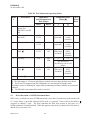
There are seven DAS subsystem operating modes, as shown in Table III. The DAS subsystem can
be configured for only one of these seven operating modes at any time, but any combination of
operating modes can be used during any orbit. DAS services are available all of the time, and the
DAS operational duty cycle can vary from 0% to 100%. During mode transitions, the DB, DDL,
and DP services may be interrupted for about 5 sec. If the DAS Modulator is ever turned off, it will
require approximately 15 minutes warmup time after turn–on before meeting long–term frequency
stability requirements.
The DAS subsystem is only required to be operational during Spacecraft nominal science mode,
when the instruments are functioning and are producing science data. It is possible that DAS
services may also be available in non–nominal Spacecraft operating modes, such as delta–V mode
and the type of safe mode in which the Spacecraft Controls Computer (SCC) continues to function.
During nominal operation, the DAS subsystem will provide Direct Broadcast (DB) service (Mode
3) and for Direct Downlink (DDL) service (Mode 4) at scheduled times when the Spacecraft passes
over user earth stations. Typically, both Mode 3 and Mode 4 would be performed using unbalanced
SQPSK modulation which provides a Q channel with 4 times the power of the I channel. In between
times when DB and DDL science data downlinks are scheduled, the DAS subsystem would operate
in standby mode, in which RF transmission is disabled. The other operating modes will be used less
frequently, typically during checkout or contingency conditions.
4.1
Pseudo–Random Bit Stream Test
DAS mode 1 provides for PRBS data to be generated internal to the modulator for the purpose of
bit error rate (BER) checking. The DAS is designed to achieve positive link margins with a Bit Error
Rate (BER) of 10–5 prior to Reed Solomon decoding (as required by CCSDS Grade 2 of service)
on all direct–to–user communications links.
v
4.2
Direct Broadcast of MODIS Instrument Data
Direct Broadcast is a service in which real–time MODIS instrument science data and ancillary data
is broadcast directly to earth stations. Data for direct broadcast is accepted on DAS Modulator input
channel 1 only. The DAS transmits the DB data stream in real time via a QPSK-modulated X-band
downlink.
In normal operation, DAS mode 3 will be used for the direct broadcast service. In DAS mode 3,
DB data is provided with positive link margin on the higher–powered Q channel (Q:I = 4:1) and is
encoded in a single convolutional encoder. DB data is provided on channel I in DAS modes 2, 3,
4, and 6, and the I channel data is uncoded in modes 2 and 3 and is encoded in a single convolutional
encoder in modes 4 and 6.
31
DMC201198
IS20008696
20 November 1998
Table III. DAS Subsystem Operating Modes
Mode
#
Description
Input Data
and Maximum Data
Rate [Mbps]
Output Data Rate
[Mbps]
Data 1
Data 2
I
Q
Q:I
Power
Ratio
1
Pseudo–Random Bit
Stream Test
(DB, DDL, and DP
off)
N/A
N/A
75
75
1:1
2
DB only – Q:I = 1:1
(not used)
DB
13.125
N/A
13.125
(uncoded)
13.125
(serial
encoded)
1:1
3
DB only – Q:I = 4:1
DB
13.125
N/A
13.125
(uncoded)
13.125
(serial
encoded)
4:1
4
Direct Downlink,
DDL
DB
13.125
DDL
105
13.125
(DB, serial
encoded)
105
(DDL,
parallel
encoded)
4:1
5
DP1 only
N/A
DP1
150
75
75
1:1
6
Direct Playback 2,
DP2
7
Standby
(bit interleaved
for effective rate of 150
Mbps)
DB
13.125
DP2
105
13.125
(DB, serial
encoded)
105
(DP2,
parallel
encoded)
4:1
N/A
N/A
0
0
N/A
Notes:
The final output is 1/2 rate encoded data at symbol rates two times the data rates shown.
The IF and LO outputs of the DAS Modulator are switched off in Standby mode,
providing a means of disabling RF output while maintaining oscillator stability for operational
readiness.
The DB link is not required for modes #4 and #6.
4.3
Direct Downlink of ASTER Instrument Data
DDL service, in which real–time ASTER instrument science data is broadcast to earth stations with
11.3 meter dishes, is provided whenever DAS mode 4 is selected. Data for direct downlink is
accepted on channel 2 only. The DAS transmits the DDL data stream in real time via a
QPSK-modulated X-band downlink. DDL data appears only on the Q-channel for DAS mode 4,
and the Q:I power ratio is 4:1.
DMC201198
32
IS20008696
20 November 1998
The DDL service is dedicated to science data from the ASTER instrument. This service will be
activated only when ASTER is in operation and when a target 11.3 meter DAS ground station is
within range. The DDL service will be scheduled by the Flight Operations Team (FOT) based on
requests for service from user stations, and it will be controlled by the Spacecraft Controls Computer
(SCC) per Stored Command Table (SCT) uploads.
4.4
Direct Playback of Recorded Science and Housekeeping Data
Direct Playback (DP) service, in which stored science and ancillary data is broadcast to earth stations
with 11.3 meter dishes, is provided whenever DAS modes 5 or 6 is selected. There are two types
of DP service, DP1 and DP2:
d. DAS mode 5 provides DP1 service, in which data on the I and Q channels will be
bit–interleaved for an effective data rate of 150 Mbps. In this mode, the power of the
I and Q channels will be balanced (i.e. Q:I power ratio = 1:1).
e. DAS mode 6 provides DP2 service, in which direct playback data will appear only on
the Q–channel at a rate of 105 Mbps. The I–channel will be used to transmit 13.125 Mbps
of DB data. In this mode, the Q:I power ratio will be 4:1.
Direct playback data is accepted on modulator input channel 2 only. The DAS transmits the DP data
stream via a QPSK-modulated X-band downlink. The DP service can not be provided on a
continuous basis since time must be allocated for recording before playback can occur.
The DP service will be utilized only as a backup in case of any interruption of the ability to transmit
science data to ground users via the TDRSS Ku-band return link service. The DP service will not
be available simultaneously with the TDRSS Ku-band return link service. The ancillary data
transmitted in the direct playback data will be identical to that transmitted in the Ku–band services.
Users of the DPI service should only use the VCDU data after Reed Solomon decoding due to a small
number of bit errors generated in the spacecraft after the Reed Solomon encoding and before the
viterbi encoding (DPI mode only).
The anomalous conditions which would warrant DP mode service usage include:
a. HGA pointing problem
b. Tracking and Data Relay Satellite System communication path outage for any length of
time greater than Solid State Recorder (SSR) recording capabilities
c. EOS Data Operations System (EDOS) outage for any length of time greater than SSR
recording capabilities.
4.5
Standby
The standby mode, DAS mode 7, provides a means for disabling RF output while maintaining
oscillator stability for operational readiness. By scheduling DB and DDL services to occur over user
ground stations, interference with DSN ground stations is avoided. The standby mode disables the
DAS subsystem RF output by switching off the IF and LO outputs from the DAS Modulator.
33
DMC201198
IS20008696
20 November 1998
(This page intentionally left blank.)
DMC201198
34
IS20008696
20 November 1998
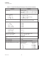
5
DAS RF CHARACTERISTICS
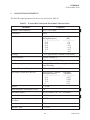
The DAS RF signal parameters for all services are listed in Table IV.
Table IV. X–band (DAS) Subsystem Performance Characteristics
Capability
Parameter
Transmit Center Frequency
8212.5 ± 0.01 MHz
Polarization
RHCP
Axial Ratio
Angle from S/C Antenna
Boresight [degrees]
––––––––––––––––––––
63.8
43.6
29.0
24.0
17.9
0
Coverage
± 63.8, approximates Constant Power Density
Data Modulation
SQPSK, USQPSK (1)
Data Format
NRZ–L: Input; NRZ–M:Output
Data Processing
Reclock, Differential Encoding, Rate 1/2 Convolutional Encoding
Assigned Frequency Range (Bandwidth)
8025 to 8400 MHz (375 MHz)
Gain Slope (10MHz min. interval)
Angle from S/C Antenna
Boresight [degrees]
––––––––––––––––––––
63.8
43.6
17.9
0
AM/PM
<7.5_/dB
Phase Imbalance with respect to ideal
< 4_
Ideal Phase Angles (2)
90_(1:1 modes), 128_, 52_ (1:4 modes)
Gain Imbalance
< 0.2 dBp–p
I/Q Data Skew (with respect to 1/2 symbol offset)
< 0.375 nsec
Data Asymmetry
< 3%
Data Rise Time
< 2.3 nsec
35
Axial Ratio
[dB]
–––––––––––––
<7.4
<9.8
<13.5
<17.0
<32.5
<10.1
Gain Slope
[dB/MHz]
–––––––––––––
0.057
0.085
0.23
0.18
DMC201198
IS20008696
20 November 1998
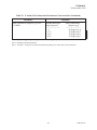
Table IV. X–band (DAS) Subsystem Performance Characteristics (Continued)
Parameter
Data Bit Jitter
In Band Flux Density
0_ < qEL < 5_
5_ < qEL < 25_
25_ < qEL < 90_
Spurious Output Out–of–band
Capability
DB and DP mode:
< 0.37 Radians for BER (< 0.37 radians for BSR)
DDL mode:
< 0.85 Radians for BER (<0.37 radians for BSR)
< –150 dBW/m2/4 kHz
< –150 +(qEL–5)/2 dBW/m2/4 kHz
< –140 dBW/m2/4 kHz
< –39dBm per Hz outside ±5% of transmit freq
–72 dBm per Hz, 2106.4 to 2112.5 MHz
Phase Noise
1 – 10 Hz
10 – 100 Hz
100 Hz – 1 kHz
1 kHz – 150 MHz
1.0_ RMS
2.0_ RMS
3.0_ RMS
2.0_ RMS
Frequency Stability
1 Second Average
5 Hour Average
48 Hour Average
± 5 x 10–12
± 3 x 10–11
± 3 x 10⁻¹⁰
System Bit Error Rate (BER)
DAS Space Segment BER
1 x 10⁻⁵ (Goal: link margin ≥ 3dB)
≤ 0.5x10⁻⁷ DB, DDL, DP2;
≤ 8x10⁻⁵ DP1
Untracked Spurious PM (1 kHz to 150
mHz)
≤ 2 degrees
Carrier Suppression
> 30 dB
Service Interruption
< 5 seconds during mode transitions
Gain Flatness (dBp–p) over ±112 MHz
Antenna Boresight
Angle [degrees]
–––––––––––––––––––
0
17.9
43.6
63.8
DMC201198
36
Gain Flatness
[dB p–p]
–––––––––––––
5.0
5 0 dBp–p
3.7 dBp–p
1.9 dBp–p
2.0 dBp–p
IS20008696
20 November 1998
Table IV. X–band (DAS) Subsystem Performance Characteristics (Continued)
Parameter
Phase Nonlinearity (degrees p–p) over
±112 MHz
Capability
Antenna Boresight
Angle [degrees]
–––––––––––––––
0
17.9
43.6
63.8
Phase Nonlinearity
[degrees p–p]
––––––––––––––––
40 degrees p–p
p p
38 degrees p–p
30 degrees p–p
29 degrees p–p
Note 1: SQPSK: Staggered QPSK; USQPSK: Unbalanced Staggered QPSK
Note 2: Resultant (transmitted) phasors
Note 3: Includes ± 0.6 degrees (circular) DAS Antenna pointing error. (total EOS system allocation).
37
DMC201198
IS20008696
20 November 1998
(This page intentionally left blank.)
DMC201198
38
IS20008696
20 November 1998
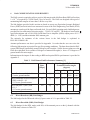
6
DAS COMMUNICATION LINK BUDGETS
The DAS system is required to achieve positive link margin with a Bit Error Rate (BER) of less than
1 x 10⁻⁵, as required by CCSDS Grade 2 level of service. The DAS was designed with a goal of
maintaining link margins of more than 3 dB for every link.
The link budgets provided in this section are based on worst case Equivalent Isotropic Radiated
Power (EIRP) and axial ratio losses measured in tests of the DAS Engineering Test Model (ETM)
antenna on a mockup of the Spacecraft nadir deck. For each DAS operating mode, link budgets are
provided for four earth station elevation angles: 5°, 40°, 63°, and 90°. The budget is based on the
specified minimum end–of–life (EOL) Solid State Power Amplifier (SSPA) output power of 11.5
dBW (i.e. 14 W) and the minimum DAS antenna gain.
The rationale for estimates of the various losses in the link budget is explained in
EOS–DN–COMM–14B.
Antenna performance test data is provided in Appendix 1 in order that the user can revise the
following link margins as required for specific operating conditions. The data shows that the DAS
system EIRP drops significantly around 20 degrees off boresight. NASA does not plan to use the
DAS direct playback service within ±24 degrees of antenna boresight (i.e. above 63.14 degrees of
ground station elevation angle).
Information on the impact of data coding to BER and required Eb/No performance is provided in
Appendix 2.
Table V. DAS Return Link Performance Summary [1]
Mode
Direct Broadcast with Q:I = 4:1
to 3 meter ground antenna
Data
Rate
[Mbps]
Channel
Link Margin (dB) For Various
Ground Elevation Angles
(degrees)
5
40
63
90
13.125
Q
5.97
10.54
0.12
3.82
6.26
9.96
Direct Downlink or Direct Playback
2 (DP2) with Q:I = 4:1
to 11.3 meter ground antenna
105
Q
6.99
11.56
4.84
10.98
Direct Playback 1 (DP1) with
Q:I=1:1
to 11.3 meter ground antenna
150
I,Q
3.6
8.17
1.45
7.59
[1] For ground system with Reed Solomon decoding.
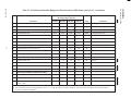
6.1
Direct Broadcast (DB) Link Budget
The link budget for the DB mode with a Q:I power ratio of 4:1 is provided in Table VI.
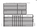
6.2
Direct Downlink (DDL) Link Budget
The link budget for the DDL mode (with 80% of the transmit power on the Q channel with the
ASTER data) is shown in Table VII.
39
DMC201198
IS20008696
20 November 1998
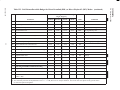
6.3
Direct Playback Link Budgets
The link budget for the the Direct Playback 1 (DP1) mode is shown in Table VIII.
The link budget for the Direct Playback 2 (DP1) mode (with 80% of the transmit power on the Q
channel with the playback data) is shown in Table VII.
DMC201198
40
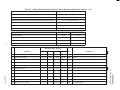
Table VI. DAS Return Downlink Budget for Direct Broadcast (DB) Mode with Q:I = 4:1
Service
DB with Q:I = 4:1
Frequency
8.2125 GHz
Polarization / AR of DAS (dB)
RHCP
Shaped DAS Antenna Pattern for Constant Power Flux Density on Earth
8dB
+ / – 63.8 degrees FOV
Ground Station Antenna Size
3 meter
Ground Station Antenna Gain (3m)
45.6 dBi; Eff = 0.55
Range at Ground Elevation Angle of 5 degrees
2574.5 kM
I Channel
Q Channel
13.125
13.125
1/2 convolutional
1/2 convolutional
Modulation
QPSK
QPSK
Data Type
NRZ–L/M
NRZ–L/M
Data Rate [Mbps]
Coding
41
Gnd Station Elev Angle / DAS Ant
Boresight Angle [degrees]
5 / 63.8
40 / 43.6
63 / 24
90 / 0
Units
Comments
1
DAS Antenna Transmitter Output Power
11.5
11.5
11.5
11.5
dBW 14 W RF, per spec, EOL
2
Passive Circuit Loss
–1.89
–1.89
–1.89
–1.89
dB
per spec
3
EOS TX Antenna Gain
6.20
–1.00
–9.80
–6.00
dBi
measured, worst case
4
EOS DAS DB EIRP
15.81
8.61
–0.19
3.61
dB
Sum 1 through 3
5
Antenna Pointing Loss
0.00
0.00
0.00
0.00
dB
Included in Ant spec
6
Polarization Loss
–1.10
–1.28
–2.15
–1.10
dB
TX/RX axial ratio: 8dB or measured worst case/1.50dB
7
Free Space Loss
–178.95
–170.99
–168.17
–167.70
dB
2575,1029,744,705 km
8
Atmospheric Absorption Loss
–0.80
–0.10
–0.10
–0.10
dB
50% humidity, 20°C
9
Rain Attenuation Loss
–1.70
–0.40
–0.20
–0.10
dB
4mm/hr rain rate
10
Ground Station Antenna Gain
45.60
45.60
45.60
45.60
dBi
3m, eff = 55%
11
Received Carrier Power
–121.14
–118.56
–125.62
–119.79
dBW sum of 4 through 10
IS20008696
20 November 1998
DMC201198
Parameter
Gnd Station Elev Angle / DAS Ant
Boresight Angle [degrees]
Parameter
5 / 63.8
40 / 43.6
63 / 24
90 / 0
Units
Comments
42
12
Ground Station Noise Temperature, K
180.00
155.00
155.00
155.00
deg K
clear sky
13
Noise Temperature Increase Due to Rain, K
116.00
32.00
18.00
6.00
deg K
estimate
14
Total Noise Temp in dB
24.71
22.72
22.38
22.07
dBK
296,187,173,161 deg K
15
Ground Station G/T
20.89
22.88
22.88
23.53
dB/K
G/T degraded by rain
16
Boltzmann’s Constant
–228.60
–228.60
–228.60
–228.60
dB/Hz/K
17
Received Carrier to Noise Density Ration (C/No)
82.75
87.32
80.60
86.74
dB/Hz
(11–14–16)
18
Convert C to Eb
71.18
71.18
71.18
71.18
dB–bps
10*log(13.125e6)
19
Ground Multipath Degradation
0.00
0.00
0.00
0.00
dB
20
Differential Encoder / Decoder Loss
–0.20
–0.20
–0.20
–0.20
dB
21
I–Q Channel Power Split Loss
–1.20
–1.20
–1.20
–1.20
dB
User to supply (Note [1])
4:1 power ratio with tolerance
Link margin Without Reed Solomon Decoding
22
Received Eb/No
10.37
14.94
8.22
14.36
dB
23
Implementation Loss
–2.0
–2.0
–2.0
–2.0
dB
24
Required Eb/No (1/2 CONV)
4.20
4.20
4.20
4.20
dB
25
SYSTEM LINK MARGIN (1/2 CONV)
4.17
8.74
2.02
8.16
dB
26
LINK MARGIN ABOVE 3DB GOAL(1/2 CONV)
1.17
5.74
–0.98
5.16
dB
Note [2]
(21+22–23)
Link margin With Reed Solomon Decoding
27
Required Eb/No (1/2/ CONV + RS)
2.40
2.40
2.40
2.40
dB
28
SYSTEM LINK MARGIN (1/2 CONV + RS)
5.97
10.54
3.82
9.96
dB
29
LINK MARGIN ABOVE 3DB GOAL (1/2
CONV + RS)
2.97
7.54
0.82
6.96
dB
(21+22–26)
[1] User should provide a value for the Ground Multipath Degradation because this item in budget depends on the ground station design.
[2] The uncertainty band for the implementation loss is +/– 0.3 dB, based on two analysis methods. The actual value will depend on the ground station
as well as the spacecraft segment.
IS20008696
20 November 1998
DMC201198
Table VI. DAS Return Downlink Budget for Direct Broadcast (DB) Mode with Q:I=4:1 (continued)
Table VII. DAS Return Downlink Budget for Direct Downlink (DDL) or Direct Playback 2 (DP2) Modes
Service
DDL or DP2
Frequency
8.2125 GHz
Polarization / AR of DAS (dB)
RHCP
Shaped DAS Antenna Pattern for Constant Power Flux Density on Earth
8dB
+ / – 63.8 degrees FOV
Ground Station Antenna Size
11.3 meter
Ground Station Antenna Gain (3m)
56.1 dBi; Eff = 0.55
Range at Ground Elevation Angle of 5 degrees
2574.5 kM
43
I Channel
Q Channel
Data Rate [Mbps]
n/a
105
Coding
n/a
1/2 convolutional
Modulation
n/a
QPSK
Data Type
n/a
NRZ–L/M
Gnd Station Elev Angle / DAS Ant
Boresight Angle [degrees]
5 / 63.8
40 / 43.6
63 / 24
90 / 0
Units
Comments
1
DAS Antenna Transmitter Output Power
11.5
11.5
11.5
11.5
dBW
2
Passive Circuit Loss
–2.14
–2.14
–2.14
–2.14
dB
per spec
3
EOS TX Antenna Gain
6.00
–1.20
–10.00
–6.20
dBi
measured, worst case
4
EOS DAS DDL EIRP
15.36
8.16
–0.64
3.16
dB
Sum 1 through 3
5
Antenna Pointing Loss
0.00
0.00
0.00
0.00
dB
Included in Ant spec
6
Polarization Loss
–1.10
–1.28
–2.15
–1.10
dB
TX/RX axial ratio: 8dB or measured worst case/1.50dB
7
Free Space Loss
–178.95
–170.99
–168.58
–167.70
dB
2575,1029,744,705 km
8
Atmospheric Absorption Loss
–0.80
–0.10
–0.10
–0.10
dB
50% humidity, 20°C
9
Rain Attenuation Loss
–1.70
–0.40
–0.20
–0.10
dB
4mm/hr rain rate
10
Ground Station Antenna Gain
57.30
57.30
57.30
57.30
dBi
11.3m, eff = 55%
11
Received Carrier Power
–109.89
–107.31
–114.37
–108.54
dBW
14 W RF, per spec, EOL
sum of 4 through 10
IS20008696
20 November 1998
DMC201198
Parameter
Gnd Station Elev Angle / DAS Ant Boresight
Angle [degrees]
Parameter
5 / 63.8
40 / 43.6
63 / 24
90 / 0
Units
Comments
44
12
Ground Station Noise Temperature, K
180.00
155.00
155.00
155.00
deg K
clear sky
13
Noise Temperature Increase Due to Rain, K
116.00
32.00
18.00
6.00
deg K
estimate
14
Total Noise Temp in dB
24.71
22.72
22.38
22.07
dBK
296,187,173,161 deg K
15
Ground Station G/T
32.59
34.58
34.58
35.23
dB/K
G/T degraded by rain
16
Boltzmann’s Constant
–228.60
–228.60
–228.60
–228.60
dB/Hz/K
17
Received Carrier to Noise Density Ration (C/No)
94.00
98.57
91.85
97.99
dB/Hz
(11–14–16)
18
Convert C to Eb
80.21
80.21
80.21
80.21
dB–bps
10*log(105e6)
19
Ground Multipath Degradation
0.00
0.00
0.00
0.00
dB
20
Differential Encoder / Decoder Loss
–0.20
–0.20
–0.20
–0.20
dB
21
I–Q Channel Power Split Loss
–1.20
–1.20
–1.20
–1.20
dB
User to supply (Note [1])
1:4 pwr ratio w/ tolerance
Link margin Without Reed Solomon Decoding
22
Received Eb/No
12.39
16.96
10.24
16.38
dB
23
Implementation Loss
–3.0
–3.0
–3.0
–3.0
dB
24
Required Eb/No (1/2 CONV)
4.20
4.20
4.20
4.20
dB
25
SYSTEM LINK MARGIN (1/2 CONV)
5.19
9.76
3.04
9.18
dB
26
LINK MARGIN ABOVE 3DB GOAL(1/2 CONV)
2.19
6.76
0.04
6.18
dB
Note [2]
(22+23–24)
Link margin With Reed Solomon Decoding
27
Required Eb/No (1/2/ CONV + RS)
2.40
2.40
2.40
2.40
dB
28
SYSTEM LINK MARGIN (1/2 CONV + RS)
6.99
11.56
4.84
10.98
dB
29
LINK MARGIN ABOVE 3DB GOAL (1/2
CONV + RS)
3.99
8.56
1.84
7.98
dB
(22+23–27)
[1] User should provide a value for the Ground Multipath Degradation because this item in budget depends on the ground station design.
[2] The uncertainty band for the implementation loss is +/– 1.9 dB, based on two analysis methods. The actual value will depend on the ground station
as well as the spacecraft segment.
IS20008696
20 November 1998
DMC201198
Table VII. DAS Return Downlink Budget for Direct Downlink (DDL) or Direct Playback 2 (DP2) Modes (continued)
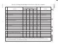
Table VIII. DAS Return Downlink Budget for Direct Playback 1 (DP1) Mode
Service
DP1
Frequency
8.2125 GHz
Polarization / AR of DAS (dB)
RHCP
Shaped DAS Antenna Pattern for Constant Power Flux Density on Earth
8dB
+ / – 63.8 degrees FOV
Ground Station Antenna Size
11.3 meter
Ground Station Antenna Gain (3m)
56.1 dBi; Eff = 0.55
Range at Ground Elevation Angle of 5 degrees
2574.5 kM
I Channel
Q Channel
75
75
1/2 convolutional
1/2 convolutional
Modulation
QPSK
QPSK
Data Type
NRZ–L/M
NRZ–L/M
Data Rate [Mbps]
Coding
45
Gnd Station Elev Angle / DAS Ant Boresight
Angle [degrees]
Parameter
5 / 63.8
40 / 43.6
63 / 24
90 / 0
Units
Comments
DAS Antenna Transmitter Output Power
11.5
11.5
11.5
11.5
dBW
14 W RF, per spec, EOL
2
Passive Circuit Loss
–2.09
–2.09
–2.09
–2.09
dB
per spec
3
EOS TX Antenna Gain
6.10
–1.10
–9.90
–6.10
dBi
measured, worst case
4
EOS DAS DPI EIRP
15.51
8.31
–0.49
3.31
dB
Sum 1 through 3
5
Antenna Pointing Loss
0.00
0.00
0.00
0.00
dB
Included in Ant spec
6
Polarization Loss
–1.10
–1.28
–2.15
–1.10
dB
TX/RX axial ratio: 8dB/1.50dB
7
Free Space Loss
–178.95
–170.99
–168.17
–167.70
dB
2575,1029,744,705 km
8
Atmospheric Absorption Loss
–0.80
–0.10
–0.10
–0.10
dB
50% humidity, 20°C
9
Rain Attenuation Loss
–1.70
–0.40
–0.20
–0.10
dB
4mm/hr rain rate
10
Ground Station Antenna Gain
57.30
57.30
57.30
57.30
dBi
10m, eff = 55%
11
Received Carrier Power
–109.74
–107.16
–114.22
–108.39
dBW
sum of 4 through 10
IS20008696
20 November 1998
DMC201198
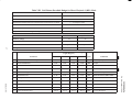
1
Gnd Station Elev Angle / DAS Ant
Boresight Angle [degrees]
Parameter
5 / 63.8
40 / 43.6
63 / 24
90 / 0
Units
Comments
46
12
Ground Station Noise Temperature, K
180.00
155.00
155.00
155.00
deg K
clear sky
13
Noise Temperature Increase Due to Rain, K
116.00
32.00
18.00
6.00
deg K
estimate
14
Total Noise Temp in dB
24.71
22.72
22.38
22.07
dBK
296,187,173,161 deg K
15
Ground Station G/T
32.59
34.58
34.58
35.23
dB/K
G/T degraded by rain
16
Boltzmann’s Constant
–228.60
–228.60
–228.60
–228.60
dB/Hz/K
17
Received Carrier to Noise Density Ration (C/No)
94.15
98.72
92.00
98.14
dB/Hz
(11–14–16)
18
Convert C to Eb
78.75
78.75
78.75
78.75
dB–bps
10*log (75e6)
19
Ground Multipath Degradation
0.00
0.00
0.00
0.00
dB
20
Differential Encoder / Decoder Loss
–0.20
–0.20
–0.20
–0.20
dB
21
I–Q Channel Power Split Loss
–3.20
–3.20
–3.20
–3.20
dB
12.00
16.57
9.85
15.99
dB
User to Supply (Note [1])
1:1 pwr ratio w/ tolerance
Link margin Without Reed Solomon Decoding
22
Received Eb/No
23
Implementation Loss
6.0
6.0
6.0
–6.0
dB
24
Required Eb/No (1/2 CONV)
4.20
4.20
4.20
4.20
dB
25
SYSTEM LINK MARGIN (1/2 CONV)
1.8
6.37
–0.35
5.79
dB
26
LINK MARGIN ABOVE 3DB GOAL(1/2 CONV)
–1.2
3.37
–3.35
2.79
dB
Note [2]
(22+23–24)
Link margin With Reed Solomon Decoding
27
Required Eb/No (1/2 CONV + RS)
2.40
2.40
2.40
2.40
dB
28
SYSTEM LINK MARGIN (1/2 CONV + RS)
3.6
8.17
1.45
7.59
dB
29
MARGIN ABOVE 3DB GOAL (1/2 CONV + RS)
0.6
5.17
–1.55
4.59
dB
(22+23–27)
[1] User should provide a value for the Ground Multipath Degradation because this item in budget depends on the ground station design.
[2] The uncertainty band for the implementation loss is +/– 1.1 dB, based on two analysis methods. The actual value will depend on the ground station
as well as the spacecraft segment. Loss includes allowance for degradation of Reed Solomon decoding from small number of bit errors generated in
spacecraft after the Reed Solomon encoding and before viterbi encoding.
IS20008696
20 November 1998
DMC201198
Table VIII. DAS Return Downlink Budget for Direct Playback 1 (DP1) Mode (continued)
IS20008696
20 November 1998
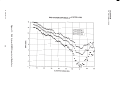
APPENDIX 1
ANTENNA PERFORMANCE DATA
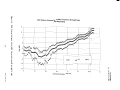
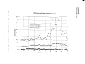
This section provides DAS system test data for reference only. The measured variation in the DAS
system EIRP, gain, and axial ratio as a function of ground antenna elevation angle are shown in
Figures 13, 14, and 15, respectively.
If it is desired to evaluate the link budget for a different ground elevation angle from the ones shown
in this document, the EIRP and polarization loss (rows 4 and 6) in the link budgets can be updated
using the information in Figure 13.
The DAS system tests were performed using an Engineering Test Model (ETM) antenna mounted
on a mockup of the nadir face of the Spacecraft.
The data in these three figures is a weighted average of the ETM antenna measurements at five
frequencies, in which the data is integrated with respect to power spectral density occupancy of the
DP1 150/150 Mbps (I/Q) signal. The following factors should be used to adjust the data in these
figures for other data rates:
Symbol Rate
Correction Factor
26 Mps
+0.3 dB
210 Mps
–0.2 dB
47
DMC201198
IS20008696
20 November 1998
DMC201198
Figure 13. DAS System EIRP Minus Axial Ratio Loss
48
IS20008696
20 November 1998
DMC201198
Figure 14. DAS System Antenna Gain (dBi) Versus Antenna Boresight Angle
49
IS20008696
20 November 1998
50
Figure 15. DAS System Axial Ratio Versus Ground Antenna Elevation Angle
DMC201198
IS20008696
20 November 1998
APPENDIX 2
IMPACT OF DATA CODING ON REQUIRED EB/NO AND BIT ERROR RATE
This appendix provides information about how the BER and required Eb/No depends on the type
of data coding performed by the ground system.
Eb/No is the ratio of received energy–per–bit (i.e. the received power times the bit duration) to the
noise spectral density. The receiver noise bandwidth is determined by the data rate and the choice
of modulation and coding.
The DAS communications link model shown in Figure 4 illustrates a concatenated coding scheme
in which Reed–Solomon (RS) coding and then convolution (CONV) encoding are applied on the
Spacecraft prior to transmission to the earth station. At the earth station, it is assumed that a
demodulator will employ a 3–bit soft–decision Viterbi (CONV) decoding process and that the
subsequent bit stream will be Reed–Solomon decoded prior to delivery to the data users.
Data arrives at the DAS Modulators on the Spacecraft in an NRZ–L format and is converted to an
NRZ–M format prior to convolutional encoding. In the NRZ–M format, data values are defined by
either a change in value from the Nth to the (N+1st)bit (logic 1) or by no change in value from the
Nth to the (N+1st) bit (logic 0). The differential encoding process, in which the format is changed
from NRZ–M to NRZ–L, doubles the bit error rate because a single–bit error in the NRZ–M data
stream produces two adjacent errors after conversion to the NRZ–L data format.
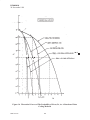
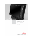
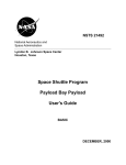
Figure 16 illustrates the significant benefits of data coding by showing the probability of error, Pe,
as a function of Eb/No performance associated with several types of data coding. For a BER of 1
x 10–5, the required Eb/No values range from 9.6 dB for the case of no coding to 4.2 dB for
convolution encoding only to greater than 2.4 dB for convolution plus Reed–Solomon coding (with
I=4).
The link budgets provided in Section 6 are provided for two points on Figure 16:
a. Point A: Convolutional Encoding (length 7, rate 1/2) Only requires a Eb/No of 4.2 dB
to achieve a BER of 1 x 10⁻⁵
b. Point B:
Reed Solomon plus Convolutional Encoding requires a Eb/No of greater than
2.4 dB to achieve a BER of 1 x 10⁻⁵
51
DMC201198
IS20008696
20 November 1998
I
B
D
A
w5
D
Figure 16. Theoretical Curves of The Probability of Error, Pe, As A Function of Data
Coding Methods
DMC201198
52
IS20008696
20 November 1998
APPENDIX 3
ACRONYM LIST
AM
Amplitude Modulation
AZ
Azimuth
BER
Bit Error Rate
Bif–S
Biphase Space
BOL
Beginning of Life
bps
bits per second
BPSK
Binary Phase Shift Keyed
BRF
Band Reject Filter
CADU
Channel Access Data Unit
CCSDS
Consulting Consortium of Space Data Systems
C&DH
Command and Data Handling Subsystem
CMD
Command
COMMS
Communications Subsystem
C&T
Command and Telemetry
CTIU
Command/Telemetry Interface Unit
DAS
Direct Access System
dc
Direct Current
DB
Direct Broadcast
dB
decibel
DDL
Direct Downlink
DG
Data Group, as defined in STDN 101.2
DP
Direct Playback
DSN
Deep Space Network
EDAC
Error Detection and Correction
EIRP
Effective Isotropic Radiated Power
EL
Elevation
EOC
EOS Operations Center
EOL
End of Life
EOS
Earth Observation System
53
DMC201198
IS20008696
20 November 1998
EOSDIS
Earth Observation System Data Information System
EPGN
EOS Polar Ground Network
ESD
Electrostatic Discharge
FDIR
Fault Detection, Isolation, and Recovery
FOT
Flight Operations Team
GHz
Giga Hertz
GN
Ground Network
HGA
High Gain Antenna
H/K
Housekeeping Telemetry
H&S
Health and Safety Telemetry
Hz
Hertz
ICD
Interface Control Drawing
IF
Intermediate Frequency
I/O
Input/Output
Kbps
kilobits per second
kHz
Kilohertz
KSA
Ku–band Single Access
LHCP
Left Hand Circularly Polarized
LNA
Low Noise Amplifier
LPC
Load Power Conditioner
M
Mode, as defined in STDN 101.2
Mbps
Megabits per second
Msps
Megasymbols per second
MHz
Megahertz
MO
Master Oscillator
N/A
Not Applicable
NASA
National Aeronautics and Space Administration
NCO
Numerically Controlled Oscillator
NRZ–L
Non–Return to Zero Level
NRZ–M
Non–Return to Zero Mark
OCXO
Ovenized Crystal Oscillator
omni
omnidirectional
DMC201198
54
IS20008696
20 November 1998
PCB
Printed Circuit Board
PLL
Phase Lock Loop
PM
Phase Modulation
PN
Pseudorandom Noise
pps
pulses per second
PBSG
Pseudorandom Bit Stream Generator
PRBS
Pseudo Random Bit Stream
PWM
Phase Width Modulated
QPSK
Quadrature Phase Shift Keying
RF
Radio Frequency
RFI
Radio Frequency Interference
RHCP
Right Hand Circularly Polarized
RT
Remote Terminal
SCC
Spacecraft Control Computer
SFE
Science Formatting Equipment
SQPN
Staggered Quadriphase Pseudorandom Noise
SQPSK
Staggered Quadrature Phase Shift Keying
SSR
Solid State Recorder
STDN
Spaceflight Tracking and Data Network
TCXO
Temperature Compensated Drystal Oscillator
TDRSS
Tracking and Data Relay Satellite System
TLM
Telemetry
VCO
Voltage Controlled Oscillator
VSWR
Voltage Standing Wave Ratio
WGS
Waveguide Switch
WPS
Wallops Island Station
WSGT
White Sands Ground Tracking
X–band RFICD
NASA document 5310–RFICD–EOS–AM–1/EPGN
55
DMC201198