1
TMS320C6000 DSK
Board Support Library
API User’s Guide
Preliminary
Literature Number: SPRU432
October 2000
Printed on Recycled Paper
IMPORTANT NOTICE
Texas Instruments and its subsidiaries (TI) reserve the right to make changes to their products
or to discontinue any product or service without notice, and advise customers to obtain the latest
version of relevant information to verify, before placing orders, that information being relied on
is current and complete. All products are sold subject to the terms and conditions of sale supplied
at the time of order acknowledgment, including those pertaining to warranty, patent infringement,
and limitation of liability.
TI warrants performance of its semiconductor products to the specifications applicable at the
time of sale in accordance with TI’s standard warranty. Testing and other quality control
techniques are utilized to the extent TI deems necessary to support this warranty. Specific testing
of all parameters of each device is not necessarily performed, except those mandated by
government requirements.
Customers are responsible for their applications using TI components.
In order to minimize risks associated with the customer’s applications, adequate design and
operating safeguards must be provided by the customer to minimize inherent or procedural
hazards.
TI assumes no liability for applications assistance or customer product design. TI does not
warrant or represent that any license, either express or implied, is granted under any patent right,
copyright, mask work right, or other intellectual property right of TI covering or relating to any
combination, machine, or process in which such semiconductor products or services might be
or are used. TI’s publication of information regarding any third party’s products or services does
not constitute TI’s approval, warranty or endorsement thereof.
Copyright 2000, Texas Instruments Incorporated
Preface
About This Manual
The TMS320C6000t DSK Board Support Library (BSL) is a set of application
programming interfaces (APIs) used to configure and control all on-board devices. It is intended to make it easier for developers by eliminating much of the
tedious grunt-work usually needed to get algorithms up and running in a real
system.
Some of the advantages offered by the BSL include: device ease of use, a level
of compatibility between devices, shortened development time, portability,
some standardization, and hardware abstraction. A version of the BSL is available for the TMS320C6711t Developers Starter Kit (DSK).
This document is organized as follows:
- Introduction – a high level overview of the BSL
- Six BSL API module chapters
- Glossary
How to Use This Manual
The information in this document describes the contents of the
TMS320C6000t board support library (BSL) as follows:
- Chapter 1 provides an overview of the BSL, includes a table showing BSL
API module support for various C6000 devices, and lists the API modules.
- Each additional chapter discusses an individual BSL API module and pro-
vides:
J
A description of the API module
J
A table showing the APIs within the module and a page reference for
more specific information
J
A module API Reference section in alphabetical order listing the BSL
API functions, enumerations, type definitions, structures, constants,
and global variables. Examples are given to show how these elements
are used.
Read This First
iii
How
to UseConventions
This Manual/ Related Documentation From Texas Instruments
Notational
Notational Conventions
This document uses the following conventions:
Program listings, program examples, and interactive displays are shown
in a special typeface.
In syntax descriptions, the function or macro appears in a bold typeface
and the parameters appear in plainface within parentheses. Portions of a
syntax that are in bold should be entered as shown; portions of a syntax
that are within parentheses describe the type of information that should be
entered.
Macro names are written in uppercase text; function names are written in
lowercase.
TMS320C6000 devices are referred to throughout this reference guide as
C6201, C6202, etc.
Related Documentation From Texas Instruments
The following books describe the TMS320C6x devices and related support
tools. To obtain a copy of any of these TI documents, call the Texas Instruments Literature Response Center at (800) 477–8924. When ordering, please
identify the book by its title and literature number. Many of these documents
can be found on the Internet at http://www.ti.com.
TMS320C62x/C67x Technical Brief (literature number SPRU197) gives an
introduction to the ’C62x/C67x digital signal processors, development
tools, and third-party support.
TMS320C6000 CPU and Instruction Set Reference Guide (literature
number SPRU189) describes the ’C6000 CPU architecture, instruction
set, pipeline, and interrupts for these digital signal processors.
TMS320C6000 Peripherals Reference Guide (literature number SPRU190)
describes common peripherals available on the TMS320C6000 digital
signal processors. This book includes information on the internal data
and program memories, the external memory interface (EMIF), the host
port interface (HPI), multichannel buffered serial ports (McBSPs), direct
memory access (DMA), enhanced DMA (EDMA), expansion bus, clocking and phase-locked loop (PLL), and the power-down modes.
TMS320C6000 Programmer’s Guide (literature number SPRU198)
describes ways to optimize C and assembly code for the TMS320C6000
DSPs and includes application program examples.
iv
How to Use This Manual
TMS320C6000 Assembly Language Tools User’s Guide (literature number
SPRU186) describes the assembly language tools (assembler, linker,
and other tools used to develop assembly language code), assembler
directives, macros, common object file format, and symbolic debugging
directives for the ’C6000 generation of devices.
TMS320C6000 Optimizing C Compiler User’s Guide (literature number
SPRU187) describes the ’C6000 C compiler and the assembly optimizer.
This C compiler accepts ANSI standard C source code and produces assembly language source code for the ’C6000 generation of devices. The
assembly optimizer helps you optimize your assembly code.
TMS320C62x DSP Library (literature number SPRU402) describes the 32
high-level, C-callable, optimized DSP functions for general signal processing, math, and vector operations.
TMS320C62x Image/Video Processing Library (literature number
SPRU400) describes the optimized image/video processing functions
including many C-callable, assembly-optimized, general-purpose
image/video processing routines.
Read This First
v
vi
Contents
1
BSL Overview . . . . . . . . . . . . . . . . . . . . . . . . . . . . . . . . . . . . . . . . . . . . . . . . . . . . . . . . . . . . . . . . . . . 1-1
Provides an overview of the board support library (BSL), describes its beneficial features, and
lists each of its API modules.
1.1
1.2
1.3
2
AD535 API Module Description . . . . . . . . . . . . . . . . . . . . . . . . . . . . . . . . . . . . . . . . . . . . . . . 2-2
AD535 API Reference . . . . . . . . . . . . . . . . . . . . . . . . . . . . . . . . . . . . . . . . . . . . . . . . . . . . . . . 2-3
BOARD API Module . . . . . . . . . . . . . . . . . . . . . . . . . . . . . . . . . . . . . . . . . . . . . . . . . . . . . . . . . . . . . . 3-1
Provides a description of the BOARD API module, lists the individual APIs within the module,
and includes a reference section showing the API functions and constants that are applicable
to this module.
3.1
3.2
4
1-2
1-3
1-3
1-4
1-5
1-5
1-5
1-5
AD535 API Module . . . . . . . . . . . . . . . . . . . . . . . . . . . . . . . . . . . . . . . . . . . . . . . . . . . . . . . . . . . . . . . 2-1
Provides a description of the AD535 API module, lists the individual APIs within the module,
and includes a reference section with the API functions, structures, and constants that are applicable to this module.
2.1
2.2
3
BSL Introduction . . . . . . . . . . . . . . . . . . . . . . . . . . . . . . . . . . . . . . . . . . . . . . . . . . . . . . . . . . . .
BSL API Modules . . . . . . . . . . . . . . . . . . . . . . . . . . . . . . . . . . . . . . . . . . . . . . . . . . . . . . . . . . .
1.2.1 BSL API Module Support . . . . . . . . . . . . . . . . . . . . . . . . . . . . . . . . . . . . . . . . . . . . .
1.2.2 Using BSL Handles . . . . . . . . . . . . . . . . . . . . . . . . . . . . . . . . . . . . . . . . . . . . . . . . . .
BSL Project Setting . . . . . . . . . . . . . . . . . . . . . . . . . . . . . . . . . . . . . . . . . . . . . . . . . . . . . . . . .
1.3.1 User’s Program Setting . . . . . . . . . . . . . . . . . . . . . . . . . . . . . . . . . . . . . . . . . . . . . .
1.3.2 Compiler Options . . . . . . . . . . . . . . . . . . . . . . . . . . . . . . . . . . . . . . . . . . . . . . . . . . . .
1.3.3 Linker Options . . . . . . . . . . . . . . . . . . . . . . . . . . . . . . . . . . . . . . . . . . . . . . . . . . . . . .
BOARD API Module Description . . . . . . . . . . . . . . . . . . . . . . . . . . . . . . . . . . . . . . . . . . . . . . 3-2
BOARD API Reference . . . . . . . . . . . . . . . . . . . . . . . . . . . . . . . . . . . . . . . . . . . . . . . . . . . . . 3-3
BSL API Module . . . . . . . . . . . . . . . . . . . . . . . . . . . . . . . . . . . . . . . . . . . . . . . . . . . . . . . . . . . . . . . . . 4-1
Provides a description of the BSL API module and includes a reference section showing the
single API function within this module.
4.1
4.2
BSL API Module Description . . . . . . . . . . . . . . . . . . . . . . . . . . . . . . . . . . . . . . . . . . . . . . . . . 4-2
BSL API Reference . . . . . . . . . . . . . . . . . . . . . . . . . . . . . . . . . . . . . . . . . . . . . . . . . . . . . . . . . 4-3
vii
Contents
5
DIP API Module . . . . . . . . . . . . . . . . . . . . . . . . . . . . . . . . . . . . . . . . . . . . . . . . . . . . . . . . . . . . . . . . . . 5-1
Provides a description of the DIP API module, lists the individual APIs within the module, and
includes a reference section showing the single API function and constant within this module.
5.1
5.2
6
FLASH API Module . . . . . . . . . . . . . . . . . . . . . . . . . . . . . . . . . . . . . . . . . . . . . . . . . . . . . . . . . . . . . . 6-1
Provides a description of the FLASH API module, lists the individual APIs within the module,
and includes a reference section showing the API functions and constants that are applicable
to this module.
6.1
6.2
7
DIP API Module Description . . . . . . . . . . . . . . . . . . . . . . . . . . . . . . . . . . . . . . . . . . . . . . . . . . 5-2
DIP API Reference . . . . . . . . . . . . . . . . . . . . . . . . . . . . . . . . . . . . . . . . . . . . . . . . . . . . . . . . . . 5-3
FLASH API Module Description . . . . . . . . . . . . . . . . . . . . . . . . . . . . . . . . . . . . . . . . . . . . . . 6-2
FLASH API Reference . . . . . . . . . . . . . . . . . . . . . . . . . . . . . . . . . . . . . . . . . . . . . . . . . . . . . . 6-3
LED API Module . . . . . . . . . . . . . . . . . . . . . . . . . . . . . . . . . . . . . . . . . . . . . . . . . . . . . . . . . . . . . . . . . 7-1
Provides a description of the LED API module, lists the individual APIs within the module, and
includes a reference section showing the API functions and constants that are applicable to this
module.
7.1
7.2
LED API Module Description . . . . . . . . . . . . . . . . . . . . . . . . . . . . . . . . . . . . . . . . . . . . . . . . . 7-2
LED API Reference . . . . . . . . . . . . . . . . . . . . . . . . . . . . . . . . . . . . . . . . . . . . . . . . . . . . . . . . . 7-3
A
Glossary . . . . . . . . . . . . . . . . . . . . . . . . . . . . . . . . . . . . . . . . . . . . . . . . . . . . . . . . . . . . . . . . . . . . . . . . A-1
B
Index . . . . . . . . . . . . . . . . . . . . . . . . . . . . . . . . . . . . . . . . . . . . . . . . . . . . . . . . . . . . . . . . . . . . . . . Index-1
viii
Tables
1–1. BSL Modules and Include Files . . . . . . . . . . . . . . . . . . . . . . . . . . . . . . . . . . . . . . . . . . . . . . . . . . . .
1–2. BSL Support Library Name and Symbol Conventions . . . . . . . . . . . . . . . . . . . . . . . . . . . . . . . . .
1–3. BSL API Module Support for 6711 DSK . . . . . . . . . . . . . . . . . . . . . . . . . . . . . . . . . . . . . . . . . . . . .
2–1. AD535 API Summary . . . . . . . . . . . . . . . . . . . . . . . . . . . . . . . . . . . . . . . . . . . . . . . . . . . . . . . . . . . . .
3–1. BOARD API Summary . . . . . . . . . . . . . . . . . . . . . . . . . . . . . . . . . . . . . . . . . . . . . . . . . . . . . . . . . . . .
4–1. BSL API Function . . . . . . . . . . . . . . . . . . . . . . . . . . . . . . . . . . . . . . . . . . . . . . . . . . . . . . . . . . . . . . . .
5–1. DIP API Summary . . . . . . . . . . . . . . . . . . . . . . . . . . . . . . . . . . . . . . . . . . . . . . . . . . . . . . . . . . . . . . .
6–1. FLASH API Summary . . . . . . . . . . . . . . . . . . . . . . . . . . . . . . . . . . . . . . . . . . . . . . . . . . . . . . . . . . . .
7–1. LED API Summary . . . . . . . . . . . . . . . . . . . . . . . . . . . . . . . . . . . . . . . . . . . . . . . . . . . . . . . . . . . . . . .
Contents
1-3
1-4
1-4
2-2
3-2
4-2
5-2
6-2
7-2
ix
x
PRELIMINARY
Chapter 1
This chapter provides an overview of the board support library (BSL), describes its beneficial features, and lists each of its API modules.
Topic
PRELIMINARY
Page
1.1
BSL Introduction . . . . . . . . . . . . . . . . . . . . . . . . . . . . . . . . . . . . . . . . . . . . . . 1-2
1.2
BSL API Modules . . . . . . . . . . . . . . . . . . . . . . . . . . . . . . . . . . . . . . . . . . . . . 1-3
1.3
BSL Project Settings . . . . . . . . . . . . . . . . . . . . . . . . . . . . . . . . . . . . . . . . . . 1-5
1-1
PRELIMINARY
BSL Introduction
1.1 BSL Introduction
The BSL provides a C-language interface for configuring and controlling all onboard devices. The library consists of discrete modules that are built and archived into a library file. Each module represents an individual API and is referred to simply as an API module. The module granularity is architected such
that each device is covered by a single API module except the I/O Port Module,
which is divided into two API modules: LED and DIP.
How The BSL Benefits You
The BSL’s beneficial features include device ease of use, shortened development time, portability, hardware abstraction, and a level of standardization and
compatibility among devices. In general, the BSL makes it easier for you to get
your algorithms up and running in the shortest length of time.
1-2
PRELIMINARY
PRELIMINARY
BSL API Modules
1.2 BSL API Modules
For each on-board device, one header file and one source file will be generated with the following names: bsl_device.h and bsl_device.c.
Also, a library will be built for a given board:
i.e: bsl6711dsk.lib
Note : The soource files.c are archived into a single source file bsl.src.
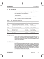
Table 1–1 provides a current list of BSL API Modules.
Table 1–1. BSL Modules and Include Files
Board
Module
Description
Include File
Module Support
Symbol
BSL
Top-level module: Initialization of the BSL
bsl_bsl.h
BSL_init
BOARD
Board-specific module – can call CSL at runtime
bsl_board.h
BOARD_SUPPORT
AD535
Audio codec module (6711 DSK)
bsl_ad535.h
AD535_SUPPORT
DIP
Dip switches module
bsl_dip.h
DIP_SUPPORT
FLASH
Flash ROM module
bsl_flash.h
FLASH_SUPPORT
LED
LED module
bsl_led.h
LED_SUPPORT
Interdependencies
Although each API module is unique, there exists some interdependency between the CSL (Chip Support Library) and BSL modules. For example, the
AD535 module depends on the MCBSP module because MCBSP0 is dedicated to serial communication.
1.2.1
BSL API Module Support
Not all API modules are supported on all boards. For example, the AIC10 module is not supported on the 6711 DSK because the board does not have an
AIC10 codec. When an API module is not supported, all of its header file information is conditionally compiled out, meaning the declarations will not exist.
Because of this, calling an AIC10 API function on a board that does not support
AIC10 results in a compiler and/or linker error.
Note: AIC10 codec is implemented on 5510evm.
PRELIMINARY
BSL Overview
1-3
PRELIMINARY
BSL API Modules
6711 DSK Module Support
Table 1–3 shows which board each API module is supported on. Currently, all
modules described in the following chapters are supported by the 6711 DSK.
In the future, more APIs supported by other platforms will be added to the BSL.
Table 1–2. BSL Support Library Name and Symbol Conventions
Board
BSL library
BSL Symbol
CSL library
CSL symbol
6711DSK
bsl6711.lib
BOARD_6711DSK
csl6711.lib
CHIP_6711
Table 1–3. BSL API Module Support for 6711 DSK
Module
1.2.2
6711 DSK
AD535
X
BOARD
X
DIP
X
FLASH
X
LED
X
Using BSL Handles
Handles are required for devices present more than once. For example, only
one AD535 codec is implemented on-board and associated with mcbsp0;
however, you can use a second AD535 implemented on a daughter board and
make data transfers through mcbsp1.
1-4
PRELIMINARY
PRELIMINARY
BSL Project Settings
1.3 BSL Project Settings
1.3.1
User’s Program Setting
Due to the interdependancies between CSL and BSL, the CSL is initialized by
calling the CSL_init() function followed by the BSL initialization function,
BSL_init().
Also, the two header files <csl.h> and <bsl.h> have to be included in your program in order for you to have access to the BSL APIs.
1.3.2
Compiler Options
In the Compiler Option window, the Chip and Board symbols have to be defined using the –d switch. For example,
–dCHIP_6711 –dBOARD_6711DSK
Also, the paths of the “Include” folder containing the BSL and CSL header files
have to be set with the –i switch.
1.3.3
Linker Options
The paths of the CSL and BSL libraries have to be defined. The two libraries
are named, respectively, csl6711.lib and bsl6711.lib.
Note: Device Identification Symbol
When using the BSL, it is up to the user to define a project-wide symbol from
a predetermined set to identify which device is being used. This board identification symbol is then used in the BSL header files to conditionally define
the support symbols. (See Section 3.2, API Reference, for more information.
PRELIMINARY
BSL Overview
1-5
PRELIMINARY
1-6
PRELIMINARY
PRELIMINARY
Chapter 2
AD535 API Module
This chapter provides a description of the AD535 API module, lists the individual APIs within the module, and includes a reference section showing the
API functions, structures, and constants that are applicable to this module.
Topic
PRELIMINARY
Page
2.1
AD535 API Module Description . . . . . . . . . . . . . . . . . . . . . . . . . . . . . . . . . 2-2
2.2
AD535 API Reference . . . . . . . . . . . . . . . . . . . . . . . . . . . . . . . . . . . . . . . . . . 2-3
2-1
PRELIMINARY
AD535 API Module Description
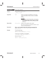
2.1 AD535 API Module Description
The AD535 module (audio codec supported by the 6711 DSK) serves as a level of abstraction such that it works the same for all AD535s supported on TI
EVM/DSKs.
To use an AD535 device, you must first open it and obtain a device handle using AD535_open(). Once opened, use the device handle to call the other API
functions. The codec may be configured by passing an AD535_Config structure to AD535_config().
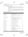
Table 2–1. AD535 API Summary
Syntax
Type
Description
Page
AD535_close
F
Closes the AD535 module
2-3
AD535_Config
S
The AD535 configuration structure used to set up an
AD535 codec
2-3
AD535_config
F
Sets up the AD535 codec using the register value
passed in
2-4
AD535_getMcbsphandle
F
Returns the Handle of the McBSP associated with the
codec previously opened
2-5
AD535_Id
S
The AD535 Identity Structure used to allocate the
Codec device and the associated McBSP
2-5
AD535_inGain
F
Sets the AD535’s input gain
2-7
AD535_micGain
F
Sets the microphone preamplifier gain
2-7
AD535_modifyReg
F
Modifies the AD535 control registers
2-8
AD535_open
F
Opens an AD535 codec for use
2-9
AD535_outGain
F
Sets the AD535’s output gain
2-10
AD535_powerDown
F
Puts the AD535 in power-down mode
2-10
AD535_read
F
Reads received data (voice channel)
2-11
AD535_readReg
F
Reads the contents of AD535 control registers
2-11
AD535_reset
F
Resets the AD535
2-12
AD535_SUPPORT
C
A compile time constant whose value is 1 if the board
supports the AD535 module
2-12
AD535_write
F
Writes data to be sent
2-12
AD535_writeReg
F
Writes to the AD535 control registers
2-13
Note:
2-2
F = Function; C = Constant; S = Structure; T = Typedef
PRELIMINARY
PRELIMINARY
AD535 API Reference
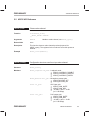
2.2 AD535 API Reference
AD535_close
Closes codec channel
Function
Void AD535_close(
AD535_Handle hAD535
);
Arguments
HAD535
Return Value
none
Description
This function closes a codec channel previously opened via
AD535_open(). The registers for the codec are set to their power-on
defaults.
Example
AD535_close(hAD535);
AD535_Config
Configuration structure used to set up codec channel
Structure
AD535_Config
Members
AD535_Loopback lb_mode Loopback mode:
AD535_LOOPBACK_DISABLE
AD535_LOOPBACK_ANALOG
AD535_LOOPBACK_DIGITAL
Handle to codec channel, see AD535_open()
AD535_MicGain mic_gain Microphone preamp gain:
AD535_MICGAIN_OFF
AD535_MICGAIN_ON
PRELIMINARY
Float in_gain
ADC input gain:
AD535_GAIN_MUTE
AD535_GAIN_0DB
–36 dB <= gain <= 12 dB
(in 1.5 dB steps)
Float out_gain
DAC output gain:
AD535_GAIN_MUTE
AD535_GAIN_0DB
–36 dB <= gain <= 12 dB
(in 1.5 dB steps)
AD535 API Module
2-3
PRELIMINARY
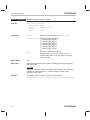
AD535 API Reference
Description
This is the AD535 configuration structure used to set up a codec channel.
You create and initialize this structure and then pass its address to the
AD535_config() function.
Example
AD535_Config myConfig = {
AD535_LOOPBACK_DISABLE,
AD535_MICGAIN_OFF,
AD535_GAIN_0DB,
AD535_GAIN_0DB
};
AD535_config(hAD535,&myConfig);
AD535_config
Sets up AD535 using configuration structure
Function
Void AD535_config(
AD535_Handle hAD535,
AD535_Config *config
);
Arguments
HAD535
Handle to codec channel, see AD535_open()
Config
Pointer to an initialized configuration structure, see
AD535_Config
Return Value
none
Description
Sets up the AD535 using the configuration structure. The values of the
structure are written to the AD535 control registers.
Example
AD535_Config myConfig = {
AD535_LOOPBACK_DISABLE,
AD535_MICGAIN_OFF,
AD535_GAIN_0DB,
AD535_GAIN_0DB
};
AD535_config(hAD535,&myConfig);
2-4
PRELIMINARY
PRELIMINARY
AD535_getMcbsp
Handle
AD535 API Reference
Returns McBSP Handle
Function
Mcbsp_Handle AD535_getMcbspHandle(
AD535_Handle hAD535,
);
Arguments
hAD535
Handle to codec channel, see AD535_open()
Return Value
Mcbsp_handle
Handle to the opened McBSP associated to the
number of McBSP.
Description
Returns the McBSP Handle associated with the McBSP used for AD535
communication.
Note: The Mcbsp_Handle type is defined in the Chip Suppport Library
(CSL) and created by the internal call of the MCBSP_open() function.
Example
Mcbsp_Handle hMcbsp;
hMcbsp = AD535_getHandleMcbsp(hAD535);
AD535_Id
Allocates codec channel
Structure
AD535_Id
Members
Typedef Struct {
Struct {
int mcbsp_no;
} Id;
Struct {
Boolean allocated;
MCBSP_Handle
hMcbsp;
} Obj;
} AD535_Id
PRELIMINARY
The typedef structure AD535_Id includes 2
substructures such as Id and Obj
structures
The internal structure Id contains the field
mcbsp_no. The member mcbsp_no
contains the number of the serial port you
wish to use.
The internal structure Obj contains the
boolean field to allocate the codec and the
McBSP handle associated with the number
of the McBSP which will be open
“mcbsp_no”.
AD535 API Module
2-5
PRELIMINARY
AD535 API Reference
Description
This AD535_Id structure is used to allocate a codec channel. You create
and initialize this structure, then pass its address to the AD535_open()
function. Also, this structure allows you to access to the McBSP handle
through the AD535_getMcbsphandle() function after calling
AD535_open().
If you wish to use the AD535 codec implemented on 6711DSK you can
pass the predefined pointer AD535_localId.
The predefined pointer AD535_locald associates the codec to the
mcbsp0 directly. It’s not necessary to define AD535_Id ponter.
mcbsp_no variable is set to 0 (mcbsp0)
See source file bsl_ad535.c
Example
/* the codec of 6711DSK use the predfined pointer AD535_localId*/
AD535_Handle hAD535;
Mcbsp_Handle hMcbsp;
hAD535 = AD535_open(AD535_localId);
hMcbsp = AD535_getHandleMcbsp(hAD535);
To set up your own AD535_Id, for example:
/* set up a codec using McBSP 1 */
AD535_Handle hAD535;
AD535_Id myId;
myId.Id.mcbsp_no = 1;
Mcbsp_Handle hMcbsp1;
hAD535 = AD535_open(*myId);
hMcbsp1 = AD535_getHandleMcbsp(hAD535);
Note: You can also use the Mcbsp1 if you haven;t opened an AD535
handle with the predefined AD535_localID object.
2-6
PRELIMINARY
PRELIMINARY
AD535 API Reference
AD535_inGain
Sets AD535’s input gain
Function
void AD535_inGain(
AD535_Handle hAD535,
float
inGain
);
Arguments
hAD535
Handle to codec channel, see AD535_open()
inGain
ADC input gain.
Return Value
none
Description
Sets the AD535’s input gain.
6711 DSK
AD535_GAIN_MUTE
AD535_GAIN_0DB
–36 dB <= inGain <= 12 dB (in 1.5 dB steps)
Example
AD535_inGain (hAD535,6.0);
AD535_micGain
Sets microphone preamplifier gain
Function
void AD535_micGain(
AD535_Handle
hAD535,
AD535_MicGain micGain
);
Arguments
hAD535
Handle to codec channel, see AD535_open()
micGain
Microphone preamplifier gain enumeration.
Return Value
none
Description
Sets the microphone preamplifier gain.
6711 DSK
AD535_MICGAIN_OFF = off, 0 dB
AD535_MICGAIN_ON = on, 20 dB
Example
AD535_micGain(hAD535,AD535_MICGAIN_OFF);
PRELIMINARY
AD535 API Module
2-7
PRELIMINARY
AD535 API Reference
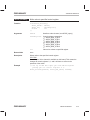
AD535_modifyReg Modifies specified control register
Function
void AD535_modifyReg(
AD535_Handle hAD535,
AD535_Reg
ad535Register,
Uint32
val,
Uint32
mask
);
Arguments
hAD535
Handle to codec channel, see AD535_open()
ad535Register
Control register enumeration:
AD535_REG_CTRL0
AD535_REG_CTRL1
AD535_REG_CTRL2
AD535_REG_CTRL3
AD535_REG_CTRL4
AD535_REG_CTRL5
val
Value to be masked into register
mask
Bit-value mask. A value of 1 sets the bit to the
corresponding value in Val; a 0 keeps the current
value of the bit.
Return Value
none
Description
Modifies the specified control register according to the bit mask (Mask)
and value (Val).
6711 DSK
Note: Only the Voice channel is available on this board. This means the
changes to control registers 0, 1, and 2 will have no effect on the
operation of the codec.
Example
To modify the ADC voice input gain in control register 4:
AD535_modifyReg(hAD535,AD535_REG_CTRL4,0x001F,0x003F);
2-8
PRELIMINARY
PRELIMINARY
AD535 API Reference
AD535_open
Opens codec channel
Function
AD535_Handle AD535_open (
AD535_Id *myId
);
Arguments
myId
Pointer to an object of type AD535_Id. This object
contains the McBSP channel number and a McBSP
handle.
6711 DSK
If you want to use the local codec, you may pass
the predefined pointer AD535_localId. If you want
to use another codec you must create your own
AD535_Id.
Return Value
AD535_Handle
Handle to newly opened codec channel
Note: If the board does not support this function, it will
return the invalid handle INV.
Description
Before a codec channel can be used, it must first be opened by this
function. Once opened, it cannot be opened again until closed. See
AD535_close().
Example
To use the local codec:
AD535_Handle hAD535;
hAD535 = AD535_open(AD535_localId);
To set up your own AD535_Id, for example:
/* set up a codec using McBSP 1 */
AD535_Handle hAD535;
AD535_Id myId;
myId.Id.mcbsp_no = 1;
hAD535 = AD535_open(*myId);
PRELIMINARY
AD535 API Module
2-9
PRELIMINARY
AD535 API Reference
AD535_outGain
Sets AD535’s output gain
Function
void AD535_outGain(
AD535_Handle hAD535,
float
outGain
);
Arguments
hAD535
Handle to codec channel, see AD535_open()
outGain
DAC output gain.
Return Value
none
Description
Sets the AD535’s output gain.
6711 DSK
AD535_GAIN_MUTE
AD535_GAIN_0DB
–36 dB <= outGain <= 12 dB (in 1.5 dB steps)
Example
AD535_outGain(hAD535,AD535_GAIN_0DB);
AD535_powerDown
Enables AD535’s power-down mode
Function
void AD535_powerDown(
AD535_Handle hAD535
);
Arguments
hAD535
Return Value
none
Description
Enables the AD535’s power down mode. This performs a software power
down, so the control registers retain their previous values.
Example
AD535_powerDown(hAD535);
2-10
Handle to codec channel, see AD535_open()
PRELIMINARY
PRELIMINARY
AD535 API Reference
AD535_read
Returns value of ouput from ADC
Function
int AD535_read(
AD535_Handle hAD535
);
Arguments
hAD535
Handle to codec channel, see AD535_open()
Return Value
int
Value returned from output of ADC.
Description
Returns the value of the ouput from the ADC.
Example
int val;
val = AD535_read(hAD535);
AD535_readReg
Returns value of specified control register
Function
Uint32 AD535_readReg(
AD535_Handle hAD535,
AD535_Reg
ad535Register
);
Arguments
hAD535
Handle to codec channel, see AD535_open()
ad535Register
Control register enumeration:
AD535_REG_CTRL0
AD535_REG_CTRL1
AD535_REG_CTRL2
AD535_REG_CTRL3
AD535_REG_CTRL4
AD535_REG_CTRL5
Return Value
Uint32
Value of specified control register.
Description
Returns the value of the specified control register.
Example
Uint32 controlRegVal;
controlRegVal = AD535_readReg(hAD535,
AD535_REG_CTRL3);
PRELIMINARY
AD535 API Module
2-11
PRELIMINARY
AD535 API Reference
AD535_reset
Asserts software reset
Function
void AD535_reset(
AD535_Handle hAD535
);
Arguments
hAD535
Return Value
none
Description
Asserts a software reset and sets all the registers to their power-on default
values.
Example
AD535_reset(hAD535);
Handle to codec channel, see AD535_open()
AD535_SUPPORT Compile time constant
Constant
AD535_SUPPORT
Description
Compile time constant that has a value of 1 if the board supports the
AD535 module and 0 otherwise. You are not required to use this constant.
Currently, all devices support this module.
Example
#if (AD535_SUPPORT)
/* do AD535 operations */
#endif
AD535_write
Writes value to input of DAC
Function
void AD535_write(
AD535_Handle hAD535,
int
val
);
Arguments
hAD535
Handle to codec channel, see AD535_open()
val
Value to be written to DAC.
Return Value
none
Description
Writes value to the input of the DAC.
Example
To read from the codec and write back the same value, use:
AD535_write(hAD535,AD535_read(hAD535));
2-12
PRELIMINARY
PRELIMINARY
AD535 API Reference
AD535_writeReg
Writes value to specified control register
Function
void AD535_writeReg(
AD535_Handle hAD535,
AD535_Reg
ad535Register,
Uint32
val
);
Arguments
hAD535
Handle to codec channel, see AD535_open()
ad535Register
Control register enumeration:
AD535_REG_CTRL0
AD535_REG_CTRL1
AD535_REG_CTRL2
AD535_REG_CTRL3
AD535_REG_CTRL4
AD535_REG_CTRL5
val
Value to be written to specified register
Return Value
none
Description
Writes value to the specified control register.
6711 DSK
Note: Only the Voice channel is available on this board. This means the
changes to control registers 0, 1, and 2 will have no effect on the
operation of the codec.
Example
/* Set up 10.5db ADC input gain and 0dB microphone
preamp gain in control register 4 */
AD535_writeReg(hAD535, AD535_REG_CTRL4, 0x0040);
PRELIMINARY
AD535 API Module
2-13
PRELIMINARY
2-14
PRELIMINARY
PRELIMINARY
Chapter 3
BOARD API Module
This chapter provides a description of the BOARD API module, lists the individual APIs within the module, and includes a reference section showing the
API functions and constants that are applicable to this module.
Topic
PRELIMINARY
Page
3.1
BOARD API Module Description . . . . . . . . . . . . . . . . . . . . . . . . . . . . . . . . 3-2
3.2
BOARD API Reference . . . . . . . . . . . . . . . . . . . . . . . . . . . . . . . . . . . . . . . . 3-3
3-1
PRELIMINARY
BOARD API Module Description
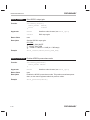
3.1 BOARD API Module Description
The BOARD module is where we put board-specific content. This module has
the potential to grow in the future as more boards are placed on the market.
Currently, the module has some API functions for register access such as
BOARD_readReg(), and BOARD_writeReg().
A predefined symbol is associated with each EVM/DSK, for example,
BOARD_6711DSK ( –d switch for compiler options setting)
Table 3–1. BOARD API Summary
Syntax
Type
Description
Page
BOARD_readReg
F
Reads a specified.BOARD memory–mapped register
3-3
BOARD_SUPPORT
C
A compile time constant whose value is 1 if the board
supports the BOARD module
3-3
BOARD_writeReg
F
Writes into a specified Board memory–mapped
register
3-4
Note:
3-2
F = Function; C = Constant; S = Structure; T = Typedef
PRELIMINARY
PRELIMINARY
BOARD API Reference
3.2 BOARD API Reference
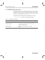
BOARD_readReg
Returns value of specified memory-mapped register
Function
Uint32 BOARD_readReg(
BOARD_Reg boardRegister
);
Arguments
boardRegister
Register enumeration
6711 DSK
BOARD_REG_IOPORT
Return Value
Uint32
Returns specified register value
Description
Returns the value of the specified memory-mapped register.
Example
Uint32 boardRegVal;
boardRegVal = BOARD_readReg(BOARD_REG_IOPORT);
BOARD_SUPPORT
Compile time constant
Constant
BOARD_SUPPORT
Description
Compile time constant that has a value of 1 if the board supports the
different modules via MODULE_SUPPORT constants and 0 otherwise. You
are not required to use this constant.
Currently, all devices support this module.
Example
#if (BOARD_SUPPORT)
/* do DIP operations */
#endif
PRELIMINARY
BOARD API Module
3-3
PRELIMINARY
BOARD API Reference
BOARD_writeReg
Writes value to specified memory-mapped register
Function
void BOARD_writeReg(
BOARD_Reg boardRegister,
Uint32
val
);
Arguments
boardRegister
Register enumeration
6711 DSK
BOARD_REG_IOPORT
val
Value to be written to specified register.
Return Value
none
Description
Writes the value to the specified memory-mapped register.
Example
BOARD_writeReg(BOARD_REG_IOPORT, 0x00000000);
3-4
PRELIMINARY
PRELIMINARY
Chapter 4
BSL API Module
This chapter provides a description of the BSL API module and includes a
reference section showing the single API function within this module.
Topic
PRELIMINARY
Page
4.1
BSL API Module Description . . . . . . . . . . . . . . . . . . . . . . . . . . . . . . . . . . . 4-2
4.2
BSL API Reference . . . . . . . . . . . . . . . . . . . . . . . . . . . . . . . . . . . . . . . . . . . . 4-3
4-1
PRELIMINARY
BSL API Module Description
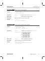
4.1 BSL API Module Description
The BSL module serves to initialize the API modules supported by the
board.The following unique function has to be called before using the API functions:
BSL_init ()
Table 4–1. BSL API Function
Syntax
Type
Description
Page
BSL_init
F
Initializes the BSL library
4-3
Note:
4-2
F = Function; C = Constant; S = Structure; T = Typedef
PRELIMINARY
PRELIMINARY
BSL API Reference
4.2 BSL API Reference
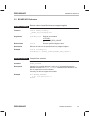
BSL_init
Initializes all programmable modules on board
Function
void BSL_init();
Arguments
none
Return Value
none
Description
This function initializes all of the programmable modules on the board.
6711 DSK
AD535 Codec
BOARD module
DIP switch
FLASH ROM
User LEDs
Example
BSL_init();
PRELIMINARY
BSL API Module
4-3
PRELIMINARY
4-4
PRELIMINARY
PRELIMINARY
Chapter 5
This chapter provides a description of the DIP API module, lists the individual
APIs within the module, and includes a reference section showing the single
API function and constant within this module.
Topic
PRELIMINARY
Page
5.1
DIP API Module Description . . . . . . . . . . . . . . . . . . . . . . . . . . . . . . . . . . . . 5-2
5.2
DIP API Reference . . . . . . . . . . . . . . . . . . . . . . . . . . . . . . . . . . . . . . . . . . . . 5-3
5-1
PRELIMINARY
DIP API Module Description
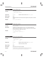
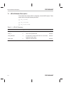
5.1 DIP API Module Description
This module has the following single API for reading DIP switch positions:
DIP_get(dip#) returns a boolean value {0,1}.
Table 5–1. DIP API Summary
Syntax
Type
Description
Page
DIP_get
F
Reads the status of the DIP switches
5-3
DIP_SUPPORT
C
A compile time constant whose value is 1 if the board
supports the DIP module
5-3
Note:
5-2
F = Function; C = Constant; S = Structure; T = Typedef
PRELIMINARY
PRELIMINARY
DIP API Reference
5.2 DIP API Reference
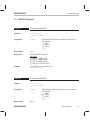
DIP_get
Returns current value of specified DIP switch
Function
Uint32 DIP_get(
Uint32 dipNum
);
Arguments
dipNum
Specifies which DIP switch to be read, can be one of
the following:
DIP_1
DIP_2
DIP_3
…
Return Value
Uint32
Current value of the specified DIP switch.
0 = DIP switch position is off.
1 = DIP switch position is on.
Description
Returns the current value of the specified DIP switch.
6711 DSK
DIP_1 = USER_SW1
DIP_2 = USER_SW2
DIP_3 = USER_SW3
Example
Uint32 val;
val = DIP_get(DIP_1);
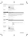
DIP_SUPPORT
Compile time constant
Constant
DIP_SUPPORT
Description
Compile time constant that has a value of 1 if the board supports the DIP
module and 0 otherwise. You are not required to use this constant.
Currently, all devices support this module.
Example
#if (DIP_SUPPORT)
/* do DIP operations */
#endif
PRELIMINARY
DIP API Module
5-3
PRELIMINARY
5-4
PRELIMINARY
PRELIMINARY
Chapter 6
FLASH API Module
This chapter provides a description of the FLASH API module, lists the individual APIs within the module, and includes a reference section showing the API
functions and constants that are applicable to this module.
Topic
PRELIMINARY
Page
6.1
FLASH API Module Description . . . . . . . . . . . . . . . . . . . . . . . . . . . . . . . . 6-2
6.2
FLASH API Reference . . . . . . . . . . . . . . . . . . . . . . . . . . . . . . . . . . . . . . . . . 6-3
6-1
PRELIMINARY
FLASH API Module Description
6.1 FLASH API Module Description
The FLASH module allows access to on-board flash and executes data
memory manipulation by using the following three functions:
FLASH_read(), FLASH_write() and FLASH_erase()
For the 6711 DSK, the 128KB FLASH is split into 128 bytes per page.
Table 6–1. FLASH API Summary
Syntax
Type
Description
Page
FLASH_checksum
F
Returns the check sum
6-3
FLASH_erase
F
Erases the specific segment of the flash and/or erases
the full flash
6-4
FLASH_read
F
Reads the Flash data and copies it to a specified
destination buffer
6-5
FLASH_SUPPORT
C
A compile time constant whose value is 1 if the board
supports the FLASH module
6-6
FLASH_write
F
Writes to Flash data from a specified source buffer
6-6
Note:
6-2
F = Function; C = Constant; S = Structure; T = Typedef
PRELIMINARY
PRELIMINARY
FLASH API Reference
6.2 FLASH API Reference
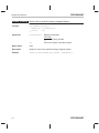
FLASH_checksum Returns checksum of specified Flash data
Function
Uint32 FLASH_checksum(
Uint32 locator,
Uint32 length
);
Arguments
locator
Addressing and page information for location in Flash
memory.
6711 DSK
FLASH_START_ADDR
FLASH_PAGE_ADDR(x) :(x)– page number
32-bit FLASH address
length
Length in bytes of data to be read. This is limited by the
size of the Flash memory.
Return Value
Uint32
Returns the value of the specified checksum
Description
Returns the checksum of the specified Flash data. Checksum calculated
by byte by byte addition.
Note: This function does not affect unspecified segments of Flash. For
example, altering the lower half of a page of Flash memory does not
change the value of the upper half page.
6711 DSK
locator contains 32-bit address of Flash location
FLASH_START_ADDR is 0x9000000
Flash address range: 0x90000000 to 0x90020000
FLASH_PAGE_SIZE = 0x80: 128 bytes
Page number range x: 0 to 1023
FLASH_PAGE_ADDR(x) = FLASH_START_ADDR +
x*FLASH_PAGE_SIZE )
Note: On 5x boards, 16-bit addressing is used and page information is
included in the upper half-word of the address argument.
Example
To get the checksum of page 0 and 1, use:
Uint32 startAddr = FLASH_PAGE_ADDR(0);
Uint32 length = FLASH_PAGE_SIZE * 2;
Uint32 checksum;
checksum = FLASH_checksum(startAddr,length);
PRELIMINARY
FLASH API Module
6-3
PRELIMINARY
FLASH API Reference
FLASH_erase
Erases specified segment of Flash memory
Function
void FLASH_erase(
Uint32 locator,
Uint32 length
);
Arguments
locator
Addressing and page information for location in Flash
memory.
6711 DSK
FLASH_START_ADDR
FLASH_PAGE_ADDR(x) :(x)– page number
32-bit Flash address
length
Length in bytes of data to be erased. This is limited by
the size of the Flash memory.
6711 DSK
length in bytes
FLASH_ERASE_ALL – erase entire FLASH
Return Value
none
Description
Erases the specified segment of Flash memory.
Note: This function does not affect unspecified segments of Flash. For
example, altering the lower half of a page of Flash memory does not
change the value of the upper half page.
6711 DSK
locator contains 32-bit address of Flash location
FLASH_START_ADDR is 0x9000000
Flash address range: 0x90000000 to 0x90020000
FLASH_PAGE_SIZE = 0x80: 128 bytes
Page number range: 0 to 1023
FLASH_PAGE_ADDR(x) = FLASH_START_ADDR +
x*FLASH_PAGE_SIZE )
Note: On 5x boards, 16-bit addressing is used and page information is
included in the upper half-word of the address argument.
Example
To erase page # 0 and # 1 in the Flash:
FLASH_erase(FLASH_PAGE_ADDR(0), FLASH_PAGE_SIZE*2);
To erase the entire FLASH:
FLASH_erase(0, FLASH_ERASE_ALL);
Note: When erasing the entire Flash memory, the locator argument
becomes a dummy parameter.
6-4
PRELIMINARY
PRELIMINARY
FLASH API Reference
FLASH_read
Reads data from FLASH address
Function
void FLASH_read(
Uint32 locator,
Uint32 dst,
Uint32 length
);
Arguments
locator
Addressing and page information for location in Flash
memory.
6711 DSK
FLASH_START_ADDR
FLASH_PAGE_ADDR(x) :(x)– page number
32-bit FLASH address
dst
Destination address
length
Length in bytes of data to be read. This is limited by the
size of the Flash memory.
Return Value
none
Description
Reads data from the FLASH address (locator) and copies it to a
destination address (dst). This function is limited only by the length of the
FLASH memory.
Note: This function does not affect unspecified segments of Flash. For
example, altering the lower half of a page of Flash memory does not
change the value of the upper half page.
6711 DSK
locator contains 32-bit address of Flash location
FLASH_START_ADDR is 0x9000000
Flash address range: 0x90000000 to 0x90020000
FLASH_PAGE_SIZE = 0x80: 128 bytes
Page number range: 0 to 1023
FLASH_PAGE_ADDR(x) = FLASH_START_ADDR +
x*FLASH_PAGE_SIZE )
Example
To read from pages 0 and 1 to readBuffer:
char readBuffer[FLASH_PAGE_SIZE*2];
FLASH_read(FLASH_PAGE_ADDR(0),
(Uint32)readBuffer,
FLASH_PAGE_SIZE * 2);
PRELIMINARY
FLASH API Module
6-5
PRELIMINARY
FLASH API Reference
FLASH_SUPPORT Compile time constant
Constant
FLASH_SUPPORT
Description
Compile time constant that has a value of 1 if the board supports the
FLASH module and 0 otherwise. You are not required to use this constant.
Currently, all devices support this module.
Example
#if (FLASH_SUPPORT)
/* do FLASH operations */
#endif
FLASH_write
Writes data to Flash address
Function
int FLASH_write(
Uint32 src,
Uint32 locator,
Uint32 length
);
Arguments
src
Source address
locator
Addressing and page information for location in Flash
memory.
6711 DSK
FLASH_START_ADDR
FLASH_PAGE_ADDR(x) :(x)– page number
32-bit FLASH address
length
Length in bytes of data to be written. This is limited by
the size of the Flash memory.
Return Value
6-6
none
PRELIMINARY
PRELIMINARY
FLASH API Reference
Description
Writes data to the Flash address (locator) from a source address (src).
This function is limited by the page length of the Flash memory.
Note: This function does not affect unspecified segments of Flash. For
example, altering the lower half of a page of Flash memory does not
change the value of the upper half page.
6711 DSK
Locator contains 32-bit address of Flash location
FLASH_START_ADDR is 0x9000000
Flash address range: 0x90000000 to 0x90020000
FLASH_PAGE_SIZE = 0x80: 128 bytes
Page number range: 0 to 1023
FLASH_PAGE_ADDR(x) = FLASH_START_ADDR +
x*FLASH_PAGE_SIZE )
If the source address begins in the middle of a page, the write will
invalidate all other data on the page.
Example
To write from writeBuffer to pages 1 and 2:
char writeBuffer[FLASH_PAGE_SIZE*2];
FLASH_write((Uint32)writeBuffer,
FLASH_PAGE_ADDR(1),
FLASH_PAGE_SIZE * 2);
PRELIMINARY
FLASH API Module
6-7
PRELIMINARY
6-8
PRELIMINARY
PRELIMINARY
Chapter 7
LED API Module
This chapter provides a description of the LED API module, lists the individual
APIs within the module, and includes a reference section showing the API
functions and constants that are applicable to this module.
Topic
PRELIMINARY
Page
7.1
LED API Module Description . . . . . . . . . . . . . . . . . . . . . . . . . . . . . . . . . . . 7-2
7.2
LED API Reference . . . . . . . . . . . . . . . . . . . . . . . . . . . . . . . . . . . . . . . . . . . . 7-3
7-1
PRELIMINARY
LED API Module Description
7.1 LED API Module Description
This module has a simple API for configuring on-board LED outputs. Three
states can be set by the following functions:
LED_on(led#)
LED_off(led#)
LED_toggle(led#)
Table 7–1. LED API Summary
Syntax
Type
Description
Page
LED_off
F
Turns off the specified LED
NO TAG
LED_on
F
Turns on the specified LED
NO TAG
LED_SUPPORT
C
A compile time constant whose value is 1 if the board
supports the LED module
NO TAG
LED_toggle
F
Toggles the specified LED
NO TAG
Note:
7-2
F = Function; C = Constant; S = Structure; T = Typedef
PRELIMINARY
PRELIMINARY
LED API Reference
7.2 LED API Reference
LED_off
Turns off specified LED
Function
void LED_off(
Uint32 LedNum
);
Arguments
LedNum
Return Value
none
Description
Turns off the specified LED.
6711 DSK
LED_1 = USER_LED1
LED_2 = USER_LED2
LED_3 = USER_LED3
LED_ALL = all user LEDs
Example
If you want to turn off LED # 1 use:
LED_off(LED_1);
LED_on
Turns on specified LED
Function
void LED_on(
Uint32 LedNum
);
Arguments
LedNum
Return Value
none
PRELIMINARY
Specifies which LED to be turned off. Can be one of
the following:
LED_1
LED_2
LED_3
…
Specifies which LED to be turned on. Can be one of
the following:
LED_1
LED_2
LED_3
…
LED API Module
7-3
PRELIMINARY
LED API Reference
Description
Turns on the specified LED.
6711 DSK
LED_1 = USER_LED1
LED_2 = USER_LED2
LED_3 = USER_LED3
LED_ALL = all user LEDs
Example
If you want to turn on LED # 1 use:
LED_on(LED_1);
LED_SUPPORT
Compile time constant
Constant
LED_SUPPORT
Description
Compile time constant that has a value of 1 if the board supports the LED
module and 0 otherwise. You are not required to use this constant.
Currently, all devices support this module.
Example
#if (LED_SUPPORT)
/* do LED operations */
#endif
LED_toggle
Toggles specified LED
Function
void LED_toggle(
Uint32 LedNum
);
Arguments
LedNum
Return Value
none
Description
Toggles the specified LED.
6711 DSK
LED_1 = USER_LED1
LED_2 = USER_LED2
LED_3 = USER_LED3
LED_ALL = all user LEDs
Example
If you want to toggle LED # 1 use:
LED_toggle(LED_1);
7-4
Specifies which LED to be toggled, can be one of the
following:
LED_1
LED_2
LED_3
…
PRELIMINARY
PRELIMINARY
Appendix
AppendixAA
A
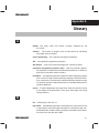
AD535: The audio codec API module. Currently supported by the
6711 DSK.
address: The location of program code or data stored; an individually
accessible memory location.
A-law companding: See compress and expand (compand).
API: See application programming interface.
API module: A set of API functions designed for a specific purpose.
application programming interface (API): Used for proprietary application programs to interact with communications software or to conform to
protocols from another vendor’s product.
assembler: A software program that creates a machine language program
from a source file that contains assembly language instructions, directives, and macros. The assembler substitutes absolute operation codes
for symbolic operation codes and absolute or relocatable addresses for
symbolic addresses.
assert: To make a digital logic device pin active. If the pin is active low, then
a low voltage on the pin asserts it. If the pin is active high, then a high
voltage asserts it.
B
bit:
A binary digit, either a 0 or 1.
big endian: An addressing protocol in which bytes are numbered from left
to right within a word. More significant bytes in a word have lower numbered addresses. Endian ordering is specific to hardware and is determined at reset. See also little endian.
PRELIMINARY
A-1
PRELIMINARY
block: The three least significant bits of the program address. These correspond to the address within a fetch packet of the first instruction being
addressed.
BOARD: The BOARD-specific API Module.
board support library (BSL): The BSL is a set of application programming
interfaces (APIs) consisting of target side DSP code used to configure
and control board level peripherals.
boot:
The process of loading a program into program memory.
boot mode: The method of loading a program into program memory. The
’C6x DSP supports booting from external ROM or the host port interface
(HPI).
BSL: See board support library.
byte:
A sequence of eight adjacent bits operated upon as a unit.
C
cache: A fast storage buffer in the central processing unit of a computer.
cache module: CACHE is an API module containing a set of functions for
managing data and program cache.
cache controller: System component that coordinates program accesses
between CPU program fetch mechanism, cache, and external memory.
CCS: Code Composer Studio.
central processing unit (CPU): The portion of the processor involved in
arithmetic, shifting, and Boolean logic operations, as well as the generation of data- and program-memory addresses. The CPU includes the
central arithmetic logic unit (CALU), the multiplier, and the auxiliary register arithmetic unit (ARAU).
CHIP:
See CHIP module.
CHIP module: The CHIP module is an API module where chip-specific and
device-related code resides. CHIP has some API functions for obtaining
device endianess, memory map mode if applicable, CPU and REV IDs,
and clock speed.
chip support library (CSL): The CSL is a set of application programming
interfaces (APIs) consisting of target side DSP code used to configure
and control all on-chip peripherals.
A-2
PRELIMINARY
PRELIMINARY
clock cycle: A periodic or sequence of events based on the input from the
external clock.
clock modes: Options used by the clock generator to change the internal
CPU clock frequency to a fraction or multiple of the frequency of the input
clock signal.
code: A set of instructions written to perform a task; a computer program or
part of a program.
codec: Coder-decoder, or compression/decompression. A device that
codes in one direction of transmission and decodes in another direction
of transmission.
coder-decoder or compression/decompression (codec): A device that
codes in one direction of transmission and decodes in another direction
of transmission.
compiler: A computer program that translates programs in a high-level language into their assembly-language equivalents.
compress and expand (compand): A quantization scheme for audio signals in which the input signal is compressed and then, after processing,
is reconstructed at the output by expansion. There are two distinct companding schemes: A-law (used in Europe) and µ-law (used in the United
States).
constant: A fixed or invariable value or data item that can be used as an operand.
control register: A register that contains bit fields that define the way a device operates.
control register file: A set of control registers.
CSL: See chip support library.
CSL module: The CSL module is the top-level CSL API module.It interfaces
to all other modules and its main purpose is to initialize the CSL library.
D
DAT: Data; see DAT module.
DAT module: The DAT is an API module that is used to move data around
by means of DMA/EDMA hardware. This module serves as a level of abstraction that works the same for devices that have the DMA or EDMA
peripheral.
PRELIMINARY
Glossary
A-3
PRELIMINARY
device ID: Configuration register that identifies each peripheral component
interconnect (PCI).
digital signal processor (DSP): A semiconductor that turns analog signals—such as sound or light—into digital signals, which are discrete or
discontinuous electrical impulses, so that they can be manipulated.
DIP: The DIP Switches API Module.
direct memory access (DMA): A mechanism whereby a device other than
the host processor contends for and receives mastery of the memory bus
so that data transfers can take place independent of the host.
DMA : See direct memory access.
DMA module: DMA is an API module that currently has two architectures
used on ’C6x devices: DMA and EDMA (enhanced DMA). Devices such
as the ’6201 have the DMA peripheral, whereas the ’6211 has the EDMA
peripheral.
DMA source: The module where the DMA data originates. DMA data is read
from the DMA source.
DMA transfer: The process of transferring data from one part of memory to
another. Each DMA transfer consists of a read bus cycle (source to DMA
holding register) and a write bus cycle (DMA holding register to destination).
DSK: Digital signal processor (DSP) starter kit. Tools and documentation
provided to new DSP users to enable rapid use of the product.
E
EDMA: Enhanced direct memory access; see EDMA module.
EDMA module: EDMA is an API module that currently has two architectures
used on ’C6x devices: DMA and EDMA (enhanced DMA). Devices such
as the ’6201 have the DMA peripheral, whereas the ’6211 has the EDMA
peripheral.
EMIF: See external memory interface; see also EMIF module.
EMIF module: EMIF is an API module that is used for configuring the EMIF
registers.
evaluation module (EVM): Board and software tools that allow the user to
evaluate a specific device.
A-4
PRELIMINARY
PRELIMINARY
external interrupt: A hardware interrupt triggered by a specific value on a
pin.
external memory interface (EMIF): Microprocessor hardware that is used
to read to and write from off-chip memory.
F
fetch packet: A contiguous 8-word series of instructions fetched by the CPU
and aligned on an 8-word boundary.
flag:
A binary status indicator whose state indicates whether a particular
condition has occurred or is in effect.
FLASH: The FLASH ROM API Module.
frame: An 8-word space in the cache RAMs. Each fetch packet in the cache
resides in only one frame. A cache update loads a frame with the requested fetch packet. The cache contains 512 frames.
G
global interrupt enable bit (GIE): A bit in the control status register (CSR)
that is used to enable or disable maskable interrupts.
H
host: A device to which other devices (peripherals) are connected and that
generally controls those devices.
host port interface (HPI): A parallel interface that the CPU uses to communicate with a host processor.
HPI: See host port interface; see also HPI module.
HPI module: HPI is an API module used for configuring the HPI registers.
Functions are provided for reading HPI status bits and setting interrupt
events.
I
index: A relative offset in the program address that specifies which of the
512 frames in the cache into which the current access is mapped.
PRELIMINARY
Glossary
A-5
PRELIMINARY
indirect addressing: An addressing mode in which an address points to
another pointer rather than to the actual data; this mode is prohibited in
RISC architecture.
instruction fetch packet: A group of up to eight instructions held in memory
for execution by the CPU.
internal interrupt: A hardware interrupt caused by an on-chip peripheral.
internal peripherals: Devices connected to and controlled by a host device.
The C6x internal peripherals include the direct memory access (DMA)
controller, multichannel buffered serial ports (McBSPs), host port interface (HPI), external memory-interface (EMIF), and runtime support timers.
interrupt: A signal sent by hardware or software to a processor requesting
attention. An interrupt tells the processor to suspend its current operation, save the current task status, and perform a particular set of instructions. Interrupts communicate with the operating system and prioritize
tasks to be performed.
interrupt service fetch packet (ISFP): A fetch packet used to service interrupts. If eight instructions are insufficient, the user must branch out of this
block for additional interrupt service. If the delay slots of the branch do
not reside within the ISFP, execution continues from execute packets in
the next fetch packet (the next ISFP).
interrupt service routine (ISR): A module of code that is executed in response to a hardware or software interrupt.
interrupt service table (IST) A table containing a corresponding entry for
each of the 16 physical interrupts. Each entry is a single-fetch packet and
has a label associated with it.
IRQ: Interrupt request; see IRQ module.
IRQ module: IRQ is an API module that manages CPU interrupts.
IST: See interrupt service table.
L
least significant bit (LSB): The lowest-order bit in a word.
LED: The LED API Module.
linker: A software tool that combines object files to form an object module,
which can be loaded into memory and executed.
A-6
PRELIMINARY
PRELIMINARY
little endian: An addressing protocol in which bytes are numbered from right
to left within a word. More significant bytes in a word have higher-numbered addresses. Endian ordering is specific to hardware and is determined at reset. See also big endian.
M
µ-law companding: See compress and expand (compand).
maskable interrupt: A hardware interrupt that can be enabled or disabled
through software.
MCBSP: See multichannel buffered serial port; see also MCBSP module.
MCBSP module: MCBSP is an API module that contains a set of functions
for configuring the McBSP registers.
memory map: A graphical representation of a computer system’s memory,
showing the locations of program space, data space, reserved space,
and other memory-resident elements.
memory-mapped register: An on-chip register mapped to an address in
memory. Some memory-mapped registers are mapped to data memory,
and some are mapped to input/output memory.
most significant bit (MSB): The highest order bit in a word.
multichannel buffered serial port (McBSP): An on-chip full-duplex circuit
that provides direct serial communication through several channels to
external serial devices.
multiplexer: A device for selecting one of several available signals.
N
nonmaskable interrupt (NMI): An interrupt that can be neither masked nor
disabled.
O
object file: A file that has been assembled or linked and contains machine
language object code.
off chip: A state of being external to a device.
on chip: A state of being internal to a device.
PRELIMINARY
Glossary
A-7
PRELIMINARY
P
peripheral: A device connected to and usually controlled by a host device.
program cache: A fast memory cache for storing program instructions allowing for quick execution.
program memory: Memory accessed through the ‘C6x’s program fetch interface.
PWR: Power; see PWR module.
PWR module: PWR is an API module that is used to configure the powerdown control registers, if applicable, and to invoke various power-down
modes.
R
random-access memory (RAM): A type of memory device in which the
individual locations can be accessed in any order.
register: A small area of high speed memory located within a processor or
electronic device that is used for temporarily storing data or instructions.
Each register is given a name, contains a few bytes of information, and
is referenced by programs.
reduced-instruction-set computer (RISC): A computer whose instruction
set and related decode mechanism are much simpler than those of microprogrammed complex instruction set computers. The result is a higher
instruction throughput and a faster real-time interrupt service response
from a smaller, cost-effective chip.
reset: A means of bringing the CPU to a known state by setting the registers
and control bits to predetermined values and signaling execution to start
at a specified address.
RTOS Real-time operating system.
S
structure: A collection of one or more variables grouped together under a
single name.
synchronous-burst static random-access memory (SBSRAM): RAM
whose contents does not have to be refreshed periodically. Transfer of
data is at a fixed rate relative to the clock speed of the device, but the
speed is increased.
A-8
PRELIMINARY
PRELIMINARY
synchronous dynamic random-access memory (SDRAM): RAM whose
contents is refreshed periodically so the data is not lost. Transfer of data
is at a fixed rate relative to the clock speed of the device.
syntax: The grammatical and structural rules of a language. All higher-level
programming languages possess a formal syntax.
system software: The blanketing term used to denote collectively the chip
support libraries and board support libraries.
T
tag:
The 18 most significant bits of the program address. This value corresponds to the physical address of the fetch packet that is in that frame.
timer: A programmable peripheral used to generate pulses or to time
events.
TIMER module: TIMER is an API module used for configuring the timer registers.
W
word: A multiple of eight bits that is operated upon as a unit. For the ‘C6x,
a word is 32 bits in length.
PRELIMINARY
Glossary
A-9
PRELIMINARY
A-10
PRELIMINARY
Index
A
A-law companding, defined, A-1
about the BSL manual, iii
AD535 API module, 2-1
API constant, 2-3
AD535_SUPPORT, 2-12
API functions
AD535_close, 2-3
AD535_config, 2-4
AD535_getMcbspHandle, 2-5
AD535_inGain, 2-7
AD535_micGain, 2-7
AD535_modifyReg, 2-8
AD535_open, 2-9
AD535_outGain, 2-10
AD535_powerDown, 2-10
AD535_read, 2-11
AD535_readReg, 2-11
AD535_reset, 2-12
AD535_write, 2-12
AD535_writeReg, 2-13
API structures
AD535_Config, 2-3
AD535_Id, 2-5
API summary table, 2-2
description, 2-2
address, defined, A-1
API, defined, A-1
B
big endian, defined, A-1
bit, defined, A-1
block, defined, A-2
BOARD API module, 3-1
API constant, 3-3
BOARD_SUPPORT, 3-3
API functions
BOARD_readReg, 3-3
BOARD_writeReg, 3-4
API summary table, 3-2
description, 3-2
board support library, defined, A-2
board support library (BSL)
6711 DSK module support, 1-4
about the BSL manual, iii
API module support, 1-3
API module support for 6711 DSK, table, 1-4
API modules, 1-3
device identification symbol, note regarding, 1-5
how the BSL benefits you, 1-2
how to use the BSL manual, iii
interdependencies, 1-3
introduction, 1-2
modules and include files, table, 1-3
notational conventions, iv
overview, 1-1
project settings, 1-5
related documents from Texas Instruments, iv
API module, defined, A-1
boot, defined, A-2
application programming interface, defined, A-1
boot mode, defined, A-2
assembler, defined, A-1
BSL, defined, A-2
assert, defined, A-1
byte, defined, A-2
Index-1
Index
C
cache, defined, A-2
cache controller, defined, A-2
CACHE module, defined, A-2
CCS, defined, A-2
central processing unit (CPU), defined, A-2
CHIP, defined, A-2
CHIP module, defined, A-2
chip support library, defined, A-2
clock cycle, defined, A-3
clock modes, defined, A-3
code, defined, A-3
coder-decoder, defined, A-3
compiler, defined, A-3
compress and expand (compand), defined, A-3
control register, defined, A-3
control register file, defined, A-3
CSL, defined, A-3
CSL module, defined, A-3
D
EMIF, defined, A-4
EMIF module, defined, A-4
evaluation module, defined, A-4
external interrupt, defined, A-5
external memory interface (EMIF), defined, A-5
F
fetch packet, defined, A-5
flag, defined, A-5
FLASH API module, 6-1
API constant, 6-3
FLASH_SUPPORT, 6-6
API functions
FLASH_checksum, 6-3
FLASH_erase, 6-4
FLASH_read, 6-5
FLASH_write, 6-6
description, 6-2
API summary table, 6-2
frame, defined, A-5
G
GIE bit, defined, A-5
DAT, defined, A-3
DAT module, defined, A-3
device ID, defined, A-4
device identification symbol, note regarding, 1-5
digital signal processor (DSP), defined, A-4
DIP API module, 5-1
API constant, 5-3
DIP_SUPPORT, 5-3
API function, DIP_get, 5-3
API summary table, 5-2
description, 5-2
direct memory access (DMA)
defined, A-4
source, defined, A-4
transfer, defined, A-4
DMA, defined, A-4
DMA module, defined, A-4
E
EDMA, defined, A-4
EDMA module, defined, A-4
Index-2
H
host, defined, A-5
host port interface (HPI), defined, A-5
how to use the BSL manual, iii
HPI, defined, A-5
HPI module, defined, A-5
I
index, defined, A-5
indirect addressing, defined, A-6
instruction fetch packet, defined, A-6
internal interrupt, defined, A-6
internal peripherals, defined, A-6
interrupt, defined, A-6
interrupt service fetch packet (ISFP), defined, A-6
interrupt service routine (ISR), defined, A-6
interrupt service table (IST), defined, A-6
IRQ, defined, A-6
Index
IRQ module, defined, A-6
IST, defined, A-6
L
least significant bit (LSB), defined, A-6
LED API module, 7-1
API constant, 7-3
LED_SUPPORT, 7-4
API functions
LED_off, 7-3
LED_on, 7-3
LED_toggle, 7-4
API summary table, 7-2
description, 7-2
linker, defined, A-6
little endian, defined, A-7
M
µ-law companding, defined, A-7
maskable interrupt, defined, A-7
MCBSP, defined, A-7
MCBSP module, defined, A-7
memory map, defined, A-7
memory-mapped register, defined, A-7
most significant bit (MSB), defined, A-7
multichannel buffered serial port (McBSP), defined,
A-7
multiplexer, defined, A-7
N
nonmaskable interrupt (NMI), defined, A-7
notational conventions, iv
O
object file, defined, A-7
off chip, defined, A-7
on chip, defined, A-7
P
peripheral, defined, A-8
program cache, defined, A-8
program memory, defined, A-8
PWR, defined, A-8
PWR module, defined, A-8
R
random-access memory (RAM), defined, A-8
reduced-instruction-set computer (RISC), defined,
A-8
register, defined, A-8
related documents from Texas Instruments, iv
reset, defined, A-8
RTOS, defined, A-8
S
STDINC module, defined, A-8
synchronous dynamic random-access memory
(SDRAM), defined, A-9
synchronous-burst static random-access memory
(SBSRAM), defined, A-8
syntax, defined, A-9
system software, defined, A-9
T
tag, defined, A-9
timer, defined, A-9
TIMER module, defined, A-9
W
word, defined, A-9
Index-3
Index-4