1
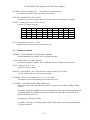
YAESU
FT-450
FT-450AT
Users Manual
18 August 2013
Authors Message
When I started this project, I did so thinking that the Yaesu Manual was too confusing and hard to learn
from. Besides, writing a User’s Manual is a great way to learn any system.
Well, I have to say, I was wrong about the first item. It turns out the Yaesu Manual is very good. It is just
that the FT-450 is a very complex machine. I continued with the effort because my second reason is still
valid. And I wanted a shorter reference manual, structured closer to the way I think, to provide myself
with a slightly different perspective of this impressive machine.
You will find that this is structured to my machine. I do not have the enhanced microphone, a linear
amplifier to boost up the power, and as yet I do not have the software in my computer to drive RTTY ,
packet, or slow scan video.
Where Yaesu’s version of the manual gives explicit instructions on an entire task, I have tried to break it
down to functional procedures and presume that the reader will learn these basic procedures so that I do
not have to spell out the specifics of every keystroke over and over again.
The only area covered by this document that was not clear in the Yaesu manual is found in section 5.2
where I discuss the interaction between M-TUNE, VFO-A, and VFO-B.
YAESU HF/50 mHz Transceiver FT-450 User’s Manual
Table of Contents
General ..................................................................................................................................... 1
Controls .................................................................................................................................... 1
2.1
Power ............................................................................................................................... 3
3
Receiver .................................................................................................................................... 4
3.1
Communications Mode ...................................................................................................... 4
3.2
Band ................................................................................................................................. 4
3.3
VFO (Variable Frequency Oscillator).................................................................................. 5
3.3.1 Clarifier ........................................................................................................................ 6
3.3.2
Split Frequency Operation .............................................................................................. 6
3.4
Extracting the Signal from the Noise ................................................................................... 7
3.4.1 RF Attenuation and Intercept Point Optimization (IPO) .................................................... 7
3.4.2 Noise Blanking .............................................................................................................. 7
3.4.3 Digital Signal Processor ................................................................................................. 7
3.4.3.1
Contour ............................................................................................................ 8
1
2
3.4.3.2
Notch ............................................................................................................... 8
3.4.3.3 Digital Noise Reduction (DNR) ....................................................................... 8
3.4.3.4
Band Pass Width............................................................................................. 8
3.4.3.5 Filter Shift ........................................................................................................ 9
3.4.4
CW Reverse .................................................................................................................. 9
3.4.4.6 CW Spotting .................................................................................................... 9
3.4.5 Radio Frequency Gain.................................................................................................... 9
3.4.5.7 Automatic Gain Control ................................................................................... 9
3.4.5.8 Radio Frequency Volume Control................................................................. 10
3.4.6
Audio Volume Control.......................................................................................... 10
3.4.7 Signal meter ................................................................................................................ 10
4
Transmitter.............................................................................................................................. 10
4.1
Transmission ................................................................................................................... 11
4.1.1 Microphone Button ...................................................................................................... 11
4.1.2 Voice Activated Transmitter Switching (VOX) .............................................................. 11
4.1.3 CW Break-In ............................................................................................................... 11
4.1.4 Data ............................................................................................................................ 11
4.2
Meter .............................................................................................................................. 11
4.3
Automatic Antenna Tuner ................................................................................................ 12
5
Channel Memories ................................................................................................................... 12
5.1
Memory Content.............................................................................................................. 12
5.2
Tuning of the VFO Setup Memory .................................................................................... 13
5.3
Band VFO Setup Memory ................................................................................................ 14
5.4
Home Memory ................................................................................................................ 14
5.5
Quick Memory ................................................................................................................ 14
5.6
Channels Memories ......................................................................................................... 15
5.6.1 Recall ......................................................................................................................... 15
5.6.2 Storage........................................................................................................................ 15
5.6.3 Removal ..................................................................................................................... 15
5.6.4 Labeling ...................................................................................................................... 15
5.7
VFO Memory Scanning ................................................................................................... 16
-i-
YAESU HF/50 mHz Transceiver FT-450 User’s Manual
6
7
8
9
5.8
Programmable Memory scanning ......................................................................................16
System Controls .......................................................................................................................16
6.1
Display Brightness ...........................................................................................................16
6.2
Semi-automatic Keyer ......................................................................................................16
6.3
Custom Switch .................................................................................................................16
Adaptation (Menu) ...................................................................................................................18
7.1
Transceiver function operational parameters ......................................................................20
7.2
Tranceiver Controls ..........................................................................................................21
7.3
Computer Aided Transceiver (CAT) Operation ..................................................................22
7.4
Adaptation of CW communication.....................................................................................22
7.5
Adaptation to exclude bands and modes .............................................................................24
7.6
Adaptation for microphone ...............................................................................................24
7.7
Adaptation of repeater communication...............................................................................24
7.8
Adaptation of Data communication....................................................................................25
7.9
Adaptation of RTTY communication .................................................................................25
7.10
Adaptation of VOX Operation...........................................................................................25
Procedural Uses .......................................................................................................................25
8.1
CW Setup ........................................................................................................................25
8.2
SSB Setup........................................................................................................................26
8.3
Antenna Testing ...............................................................................................................27
8.4
CW Training ....................................................................................................................27
Acronym Glossary....................................................................................................................28
Table of Tables
Table 1 - Controls...............................................................................................................................3
Table 2 – Communication Modes ........................................................................................................4
Table 3 – Transceiver Bands ...............................................................................................................5
Table 5 – Base frequency step size for controls ....................................................................................5
Table 6 – Band Width Filter Settings ...................................................................................................9
Table 7 – Memory Channel Number ..................................................................................................12
Table 8 – Contents of Each Memory Channel.....................................................................................13
Table 9 – 20 Unique Assignable Button Functions ..............................................................................17
Table 10 – 8 Assignable shortcuts of F followed by an existing buttons ...............................................17
Table 11 – 22 Duplicate Button Functions..........................................................................................18
Table 12 – Miscellaneous redundant or useless function......................................................................18
Table 13 – Adaptable Parameters ......................................................................................................20
Table 14 – CTCSS tone frequencies (Hz) ...........................................................................................21
- ii -
YAESU HF/50 mHz Transceiver FT-450 User’s Manual
1
General
The Yaesu FT-450 HF/50 MHz Transceiver is designed for Amateur Radio use. It provides a
general-purpose receiver covering 30 KHz through 56 MHz. The Transceiver range is broken
into 10 Amateur Radio Bands and 1 general purpose band to cover the remaining high frequency
spectrum. The variable frequency oscillator (VFO) setup for each band is remembered
individually as you switch bands. The details of what makes up a VFO setup will be described
when we get into the section on memory. The transceiver allows communication in using side
band, continuous wave, amplitude modulation, frequency modulation, and (when computer
driven) a number of data modes.
2
Controls
The FT-450 front panel contains 24 push buttons, 3 analog rotary dials, 2 rotary digital dials, a lighted
display, and three jacks. The small rotary digital dial (“DSP/SEL”) has 24 steps per revolution and also
functions as a push button. The large rotary digital dial has 100 steps per revolution. A number of push
buttons behave differently if held down for one second (adaptable).
Since there are literally hundreds of settings possible on the FT-450, a button, knob, or dial may be used
to control more than one function. The less often changed values are set by a sequence of buttons and/or
dials. For example, if you press the “F■” button (2nd from right mid height button), the letter F will
illuminate on the display. The upper right six buttons have two names on each. If the F is illuminated, the
button performs the function of the upper name and the F is extinguished. Otherwise those buttons
perform the function of the lower name.
Definitions:
f-press = press a button preceded by the “F■” button
t-press = press a button and hold for 1 second (adaptable 0.5, 1.0, 1.5, or 2.0 seconds)
-1-
YAESU HF/50 mHz Transceiver FT-450 User’s Manual
CONTROL
ON/OFF
DSP
ATT/IPO
BAND▼
ACT
T-PRESS
PRESS
PRESS
T-PRESS
PRESS
PRESS
T-PRESS
PRESS
BAND▲
PRESS
TUNE
PRESS
T-PRESS
PRESS
NB
AGC
F
T-PRESS
METER/DIM
MODE▼
PRESS
T-PRESS
PRESS
T-PRESS
MODE▲
PRESS
A=B
A/B
KEYER
CLAR
FAST
LOCK
SHIFT
DSP/SEL
T-PRESS
PRESS
PRESS
PRESS
PRESS
PRESS
PRESS
PRESS
TURN
STATE
CW
menu
menu
menu
cwtrain
power off
-menu
CW
power off
-menu
CW
-
MEMORY
PRESS
MAIN DIAL
TURN
DSP
MENU
MENU
blink
MEMORY
DSP
MENU
-
FUNCTION
Toggle system ON/OFF
Step DSP contour, notch, digital noise reduc, width, OFF
Step through combinations of ATT and IPO off and on
Voice tone to compare with CW tone to spot the frequency
Toggles noise blanker
Step automatic gain control through auto, fast, slow
Turn off automatic gain control
Steps forward through enabled bands
Steps forward through bands to enable/disable
Steps backward through enabled bands
Steps backward through bands to enable/disable
Toggle enable/disable of automatic antenna tuner
Start tuning to antenna process
Enter the “F■” (function) state
Generates the next group of 5 practice CW characters
Enter or leave the “menu” state (see section 6 adaptation)
Reset adaptation to factory default when turn power on
Step through power, ALC, standing wave ratio meter
Start brightness adjustment via DSP/SQL(end with press)
Steps forward through enabled modes
Steps forward through modes to enable/disable
Toggles between USB and LSB reception
Display software version (194) when turn power on
Steps forward through enabled modes
Steps backward through modes to enable/disable
Toggles between USB and LSB reception
Copy the current VFO settings into the secondary VFO
Swap the current and secondary VFO settings
Toggle CW keyer on/off (manual vs space assisted keying)
Allow offset of receive frequency with “MAIN” dial
Toggle increase in frequency steps for both dials
Lock frequency (see details) to avoid accidental change
Shift the intermediate frequency (IF) pass band
Small kHz steps in frequency (see Table 5)
100 KHx steps in frequency (may be adapted to set CW
side tone, CW speed, 1 mHz steps, mic gain, or rf power)
single channel steps
single groups steps
Step values for selected filter (shown by “>”)
Step through list of adaptable items
Step through allowed values fore individual items
Toggle between small and large steps in frequency
Toggle between groups and individual memory numbers
Toggle type of filter on/off, sense, magnitude (see writeup)
select menu item (blink menu display) for setting
Fine setting of frequency (end memory mode)
-2-
YAESU HF/50 mHz Transceiver FT-450 User’s Manual
CONTROL
SQL/RF GAIN
ACT
TURN
AF GAIN
VOICE/C.S
TURN
PRESS
MW/V/M
PRESS
HOME/RCL
T-PRESS
PRESS
VOX/STO
T-PRESS
PRESS
STEP/SPLIT
PRESS
PMS/SCAN
T-PRESS
PRESS
STATE
not squelch
squelch
F
F
power off
F
F MW
menu blink
power on
F
F
F
-
FUNCTION
Analog setting of radio frequency gain
Analog setting of squelch level
Analog setting of audio frequency gain
Announce the frequency and mode in voice to operator,
Customer adapted function ( see Tables 9, 10, 11, 12)
Memory write VFO setup to selected channel (1 out of 508)
Copy memorized VFO setup into current VFO
Clear memory channels when power turned on
Copy preferred (quick) VFO setup into current VFO
Copy quick VFO setup into current VFO
Copy current VFO setup into home channel
In most cases, the menu item restored to factory default
Reset adapt, clear memory channels when turn power on
Activate or deactivate voice activated transmission
Copy current VFO setup into (preferred (quick) memory
Toggle setting frequency step with DSP/SEL knob
Toggle operation using secondary VFO settings to transmit
Activate quick SPLIT operation
Toggle program memory scan between two frequencies
Toggle upward scanning of frequencies or memory channel
Table 1 - Controls
This document was derived from the information in the Yaesu HF/50 MHz Transceiver FT-450 Operation
Manual.
2.1
Power
To toggle the FT-450 transceiver ON or OFF, t-press the ON/OFF button. Some portion of
the display will show when the unit is on. Needless to say, the 12 volts must already be
supplied to the unit.
The power switch is also used to reset memory and/or adaptation in the FT-450. Warning: Do not perform
any of the first three following steps unless you are prepared to lose information:
1) Turning the power on while holding the “F■” button will restore adaptation
to the factory default settings.
2) Turning the power on while holding the “VM/V/M” button will clear all memory
channels except QMB.
3) Turning the power on while holding the “HOME/RCL” button will both
restore adaptation to the factory default settings and clear all memory channels
except QMB.
-3-
YAESU HF/50 mHz Transceiver FT-450 User’s Manual
4) Turning the power on while holding the “MODE▼” button will display the current software
version. You must then turn the power off and then on to resume normal operation.
3
Receiver
The transceiver provides both a multi-band sensitive receiver and transmitter. Most of the
controls have to do with the operation of the receiver section. However, Mode, Band, and VFO
apply to the transmitter section as well.
3.1
Communications Mode
The FT-450 transceiver is designed to communicate using Lower Side Band
(LSB), Upper Side Band (USB), Continuous Wave (CW, i.e. Morse code),
Data (DATA), Amplitude Modulation (AM), or Frequency Modulation (FM).
Pressing either the “MODE▼” or “MODE▲” will step through the available
modes in the forward or reverse direction respectively. These buttons are found to the right of the
“DSP/SEL” knob. Any unwanted modes may be turned off in adaptation using the MENU functions
described later.
Most user’s will not need all of the communication modes shown in Table 2. When you get to the section
on adaptation, you will find that you can configure the system to skip any modes that are not needed.
MODE
DESCRIPTION
USB
Upper side band
LSB
Lower side band
CW
Continuous Wave
AM
Amplitude Modulation
FM
Frequency Modulation
DATA
Radio teletype, Packet
Table 2 – Communication Modes
3.2
Band
Step through the bands using ”BAND▲” and “BAND▼” buttons on either
side of the “MAIN” dial. Only those bands enabled (via the menu
command) will be selected. The available bands are shown in Table 1
above. Any unwanted bands may be turned off in adaptation using the
MENU functions described later.
BAND
GEN
1.8 MHz
3.5 MHz
7.0 MHz
10 MHz
14 MHz
RANGE
30 KHz ~ 33 MHz
30 KHz ~ 33 MHz
30 KHz ~ 33 MHz
30 KHz ~ 33 MHz
30 KHz ~ 33 MHz
30 KHz ~ 33 MHz
-4-
AMATEUR RADIO BAND
none (stores non-ham fqys )
1.8 MHz ~ 2.0 MHz
3.5 MHz ~ 4.0 MHz
7.0 MHz ~ 7.3 MHz
10.1 MHz ~ 10.15 MHz
14 MHz ~ 14.35 MHz
YAESU HF/50 mHz Transceiver FT-450 User’s Manual
BAND
18 MHz
21 MHz
24 MHz
28 MHz
50 MHz
3.3
RANGE
AMATEUR RADIO BAND
30 KHz ~ 33 MHz
18.068 MHz ~ 18.168 MHz
30 KHz ~ 33 MHz
21 MHz ~21.45 MHz
30 KHz ~ 33 MHz
24.89 MHz ~ 24.99 MHz
30 KHz ~ 33 MHz
28 MHz ~ 29.7 MHz
33 MHz ~ 56 MHz
50 MHz ~ 54 MHz
Table 3 – Transceiver Bands
VFO (Variable Frequency Oscillator)
The display shows the current frequency in 10 Hz increments (left field is MHz, mid
field is KHz). The desired frequency is selected by rotating the “DSP/SEL” knob (24
steps per revolution). Tabke 5 shows the incremental step size. Factory defaults are
highlighted.
Press the “DSP/SEL” knob to blink the left 3 digits of
the frequency display and the “DSP/SEL” knob now
moves in 100 kHz increments changing only those
digits. Pressing the “DSP/SEL” knob again (or pressing
any button or moving the “MAIN” dial) stops the
blinking and the “DSP/SEL” knob action returns to the
smaller increment size.
The “MAIN” (large unlabeled) dial (100 steps per
revolution) allows fine-tuning of the frequency. The
“MAIN” dial is, by default, disabled in AM or FM
modes, but may be enabled by adaptation.
MODE(S)
“DSP/SEL” KNOB
CW, LSB, USB, DATA 1.0, 2.5, 5.0 kHz
AM
2.5, 5.0, 9.0, 10, 12.5, 25 kHz
FM
5.0, 6.25,10, 12,.5, 15, 20, 25, 50 kHz
Table 5 – Base frequency step size for controls
“MAIN” DIAL
1, 10, 20 Hz
100, 200 Hz *
100, 200 Hz *
*Note: By default, “MAIN” dial is inoperative for AM and FM modes unless enabled by adaptation.
To change the frequency step size of the “DSP/SEL” knob, f-press the “STEP/SPLIT” (just above “F■”).
The current step size will show on the bottom right of the display. Change the step size value by rotating
the “DSP/SEL” knob. When the correct value is displayed, press the “STEP/SPLIT” button to exit that
state.
Press the “FAST” button (to the left bottom of “MAIN” dial) to increase the speed of frequency selection.
The word FAST will be highlighted on the display, the “DSP/SEL” increments will be doubled and the
“MAIN” dial increments will be increased by a factor of 10. Pressing “FAST” again to extinguish the
FAST highlight and returns both knobs to their set increments.
The current frequency may be locked to avoid inadvertently changing it. To toggle the lock function,
press the “LOCK” button to the right of the “MAIN” dial. When locked, the word LOCK will appear
-5-
YAESU HF/50 mHz Transceiver FT-450 User’s Manual
above the right end of the frequency display. The frequency lock may be released by pressing “LOCK”
again.
In addition to the display, the FT-450 is able to announce the current frequency through
the speaker or headset. To hear the frequency, f-press the “VOICE” button (2nd upper
button from the right).
Note: Small changes in the receive frequency (under 10 kHz) my also be achieved by use
of the clarifier. See section 4.1.1 of transmission for details.
3.3.1
Clarifier
The receive frequency can be set up to +/-9.99 kHz different
from the transmit frequency. This is toggled on and off by
pressing the “CLAR” button located near the bottom middle
of the front panel. When activated, the word CLAR shows
on the right side of the display with the offset shown below
it (replacing the M-TUNE, VFO-A, or VFO-B on the
display). The offset value may be changed with the “MAIN”
dial. Note that the offset control may be re-assigned to the
“DSP/SEL” knob in adaptation using the MENU functions as described later.
The system will remember the offset value, even when CLAR is turned off. To zero the offset, t-press the
“CLAR” button while the clarifier is turned on. The offset will also be set to zero if the “MAIN” dial is
inadvertently turned when the CLAR is turned off.
3.3.2
Split Frequency Operation
The FT-450 Transceiver is capable of operating on two frequencies; one
for transmission and another for reception. Moreover, there is no restriction
that the two VFOs operate on the same band or even in the same mode.
To toggle split frequency operation, press the “STEP/SPLIT” button. The
work SPLIT is highlighted in the display. The current receive VFO setup
appears on the display. If you want to keep it, press either the “A = B” or “A
/ B” button to either put that setup in the transmit VFO or swap setups with
the current transmit VFO. Then enter the transmit frequency and any other parameters
associated with it and press the “A / B“ button to swap it with the receive VFO setup.
You are now ready to communicate. Whenever the Transceiver is transmitting, the frequency
display will show the transmit frequency. Otherwise it will show the receive frequency.
There is also a quick split feature in the system. If you t-press the “STEP/SPLIT” button, the
system will automatically copy the receive VFO into the transmit VFO and add 5 kHz to the
transmit frequency. You may now communicate as before.
Note: see section 5 for a better understanding of the contents of a VFO setup and section 5.5 a
more complete description of the “A = B” or “A / B” button action.
-6-
YAESU HF/50 mHz Transceiver FT-450 User’s Manual
3.4
Extracting the Signal from the Noise
Every stage of the FT-450 Transceiver contributes to the effort to improve the signal to noise
ratio. In order to deal with the wide dynamic range of input signals, the operator may optionally
insert 20 db of attenuation or disable the radio frequency (RF) amplifier in what is called
intercept point optimization (IPO). The RF amplifier gain is controlled by the automatic gain
control (AGC) circuitry.
The signal is then mixed with the first local oscillator to produce an intermediate frequency of
67.899 mHz, passed through a 10 kHz wide roofing filter and then passed through the first
intermediate frequency (IF) amplifier. The gain of the IF amplifier is also controlled by the AGC
circuitry.
The amplified IF signal is mixed to produce a 24 kHz second IF. The second IF signal is then
converted through an analog to digital converter (ADC). Further filtering is then performed by
the digital signal processor (DSP). The DSP then detects (DET) the signal and provides the AGC
control. The detected signal then passes through a digital to analog converter (DAC) to drive the
speaker circuitry
The operator has direct control of ATT, IPO, noise blanker (NB), several DSP filter properties,
AGC speed, IF gain (or squelch), and audio frequency (AF) gain.
3.4.1
RF Attenuation and Intercept Point Optimization (IPO)
Filtering is done first by the “ATT/IPO” button. To reduce
strong signals, apply these filters. Each time the
“ATT/IPO” button is pressed it advances through the
sequence:
ATT off, IPO off
ATT on, IPO off
ATT off, IPO on
ATT on, IPO on
3.4.2
no attenuation, input preprocessor active
20 db attenuation, input preprocessor active
no attenuation, input processor off
20 db attenuation, input processor off
Noise Blanking
Interference rejection within the bass band follows the IF filtering. This is used to filter noise from
automobiles or any other electrical sparks. It is toggled on and off by the “NB” button and the display will
show the status of the NB on the second figure top right on the display.
3.4.3
Digital Signal Processor
Pressing the “DSP” button will cause a “>” sign to
appear in front of the CONTOUR signal processing
-7-
YAESU HF/50 mHz Transceiver FT-450 User’s Manual
graph on the left side of the display. Repeated press of the “DSP” button will move the “>” sign down to
the NOTCH graph, then to the DNR graph, then to the WIDTH, and finally to remove the “>” sign. While
the “>” sign is displayed and if M-TUNE, VFO-A, or VFO-B shows on the bottom right of the screen, the
“DSP/SEL” knob is used to adjust the digital signal processor parameters.
3.4.3.1
Contour
The shape of the band pass may be rounded up or down
over a small or medium width of the band pass. That
bulge may be moved over the width of the band pass.
The first press of the “DSP” button causes the “>” sign
to be positioned next to the CONTOUR graph. Pressing
the “DSP/SEL” knob steps the filter from none to
narrow to medium with bulge. T-press the “DSP/SEL”
knob to flip between and upward or downward bulge.
Turn the “DSP/SEL” knob to position the bulge over the
different parts of the band pass.
3.4.3.2
Notch
Introducing a sharp notch in the band pass is achieved by the second
press of the “DSP” button that causes the “>” sign to be positioned
next to the NOTCH graph. Press the “DSP/SEL” knob to toggles the
filter off or on. Turn the “DSP/SEL” knob to position the bulge over
the different parts of the band pass. Note that the knob must be moved
several steps before the notch will move noticeably.
3.4.3.3
Digital Noise Reduction (DNR)
Application of one of 11 different digital Noise Reduction (DNR) filters in the band pass is achieved by
the third press of the “DSP” button that causes the “>” sign to be positioned next to the DNR indicator.
Press the “DSP/SEL” knob to toggle the DNR off or on. Rotate the “DSP/SEL” to select one of the filters
which are indicated in the number of segments lighted by listening to which sounds best.
3.4.3.4
Band Pass Width
Without any other filtering, the band pass is relatively
flat for its band pass value with relatively steep dropoff above and below that band. The fourth push of the
“DSP” button causes the “>” sign to be positioned
next to the WIDTH graph on the display. Turning the
“DSP/SEL” knob steps the filter from narrow (left),
nominal (mid), to wide (right). The actual band width
-8-
YAESU HF/50 mHz Transceiver FT-450 User’s Manual
depends on the communications mode as shown in Table 6.
MODE
CW, DATA
USB, LSB
AM
FM
3.4.3.5
NARROW
NOMINAL
WIDE
500 Hz
1.8 kHz
2.4 kHz
1.8 kHz
2.4 kHz
3.0 kHz
3.0 kHz
6.0 kHz
9.0 kHz
2.5 kHz
5.0 kHz
--------Table 6 – Band Width Filter Settings
Filter Shift
The digital signal processor center frequency can
always be shifted with the “SHIFT” knob. The
position of that center frequency is shown on the
lower left of the display.
Note: The shift value is not saved as part of the
VFO setup.
3.4.4
CW Reverse
The default CW reception injects the beat frequency in
the upper sideband of the CW carrier. In some cases, a
near signal may be filtered out by switching to the lower
sideband of the CW carrier. The sideband for CW
reception can be toggled by a t-press of either” MODE▼”
or “MODE▲”.
3.4.4.6
CW Spotting
When fine tuning a CW signal, it is sometimes helpful to zero beat with your own signal. T-press
the “ATT/IPO” button to sound your signal on top of the received signal.
3.4.5
3.4.5.7
Radio Frequency Gain
Automatic Gain Control
-9-
YAESU HF/50 mHz Transceiver FT-450 User’s Manual
The FT-450 attempts to maintain a constant audio level (assuming the signal is strong enough). In
general, we want the Automatic Gain Control (AGC) to respond quickly during CW or DATA
transmissions. However, when speech is involved we want the system to react more slowly so that voice
inflections can be heard. Status of the AGC control is shown on the upper right of the display.
Pressing the “AGC” button (to the left of the “BAND▼” button) will step
from AUTO to FAST or from FAST to SLOW or from SLOW to AUTO. If
you t-press the “AGC” button, the system will disable (or enable) the AGC.
For most uses, simply leave the AGC set to AUTO and the FT-450 will set
the AGC speed according to the current receive MODE (see next section).
3.4.5.8
Radio Frequency Volume Control
In most cases, the gain (or squelch) is turned full on by rotating the “SQL/RF
GAIN” knob fully to the right. The signal strength meter readings are only
accurate in the full on position. The “SQL/RF GAIN” knob may also be adapted to act as a squelch,
muting the sound when the signal is below a set level and/or pausing a scan operation when sufficient
signal is present.
3.4.6 Audio Volume Control
No surprises here. Adjusting the audio for the most comfortable sound by
rotation of the “AF GAIN” knob sets the volume. Turning to the right makes
most sound louder.
The system beep volume, BEEPVOL, alerting the user of system warnings as
well as CW side tone volume, CWSTONE, is set in adaptation. Either, may
be set to a fixed volume or linked to the “AF GAIN” with a user selected
offset in volume.
3.4.7
Signal meter
When not transmitting, the meter in
the upper left corner of the display
shows the signal strength of the
received signal. Note that the value is
only accurate when the “SQL/RF
GAIN” knob is turned full on (all the
way to the right).
4
Transmitter
The transmitter makes use of the mode, band, and frequency settings shown in 3.1, 3.2, and 3.3.
The current mode of transmission, LSB, USB, CW,
AM, FM, or DATA is lighted in the display. In
- 10 -
YAESU HF/50 mHz Transceiver FT-450 User’s Manual
addition, if CW mode, the display also shows whether the injected beat frequency is LSB or
USB.
When the automatic antenna tuner is engaged, the TUNER indicator is lighted. As long as the
system is receiving (or squelch is open) the BUSY indicator is lighted.
4.1
Transmission
When the system is transmitting, the TX is lighted and the BUSY is not lighted. If an attempt is
made to transmit outside of the amateur radio bands, the status area of the display (lower right
hand corner will show TX ERR and the TX indicator will not be lighted.
4.1.1
Microphone Button
The system will transmit whenever the side button on the microphone is pressed.
4.1.2
Voice Activated Transmitter Switching (VOX)
F-press the “VOX/STO” button to toggle the VOX (voice-actuated transmitter switching) system on or
off when in USB, LSB, AM, or FM modes. When the VOX is active, the VOX indicator will
show on the display. When VOX is active, speaking into the microphone will cause the
Transceiver to transmit. (Note: MH-67 microphone not operative when button released)
4.1.3
CW Break-In
F-press the “VOX/STO” button to toggle the break-in (key-actuated transmitter switching)
system on or off when in CW mode. When the break-in is active, theBK-IN indicator will
show on the display. Break-in should be on for CW transmission. Turning off break-in is
useful for code practice.
4.1.4
Data
An external computer or device may command the transceiver to transmit rtty, packet, or other data.
4.2
Meter
During transmission, one of the three
parameters is monitored (only one of
PO, ALC, or SWR titles will show on
the display). The parameters may be
stepped through by pressing the
“METER/DIM III” button just above the “AF GAIN” knob. They are PO (Power Out),
ALC (Automatic Level Control), and SWR (Standing Wave Ratio) respectively.
- 11 -
YAESU HF/50 mHz Transceiver FT-450 User’s Manual
4.3
Automatic Antenna Tuner
The built in automatic antenna tuner will match the output through a 50 ohm line if
the SWR of the antenna without the tuner is 3:1 or less. The antenna tuner is
toggled on or off by pressing the “TUNE○” button located just below the right
edge of the display. When the tuner is on, the word TUNER is displayed just above
the start of the frequency display.
To operate the automatic antenna tuner, t-press the “TUNE○” button for one
second. The TX will light up during the operation and you might hear the tuner operation
for a couple of second. If the operation fails (usually because of excessive SWR), the
antenna symbol at the start of the diagram on the display will flash until the tuner is
either turned off or run successfully.
5
Channel Memories
The FT-450 contains 508 memory channels as well as M-TUNE, VFO-A, VFO-B, QUICK, and HOME.
The memory channels may be addressed one of two ways per Table 7 according to the setting in
adaptation.
Group Memory “OFF”
Group Memory “ON”
MEM-001 ~ MEM-050
M-01-01 ~ M-01-50
MEM-051 ~ MEM-100
M-01-01 ~ M-01-50
MEM-101 ~ MEM-150
M-01-01 ~ M-01-50
MEM-151 ~ MEM-200
M-01-01 ~ M-01-50
MEM-201 ~ MEM-250
M-01-01 ~ M-01-50
MEM-251 ~ MEM-300
M-01-01 ~ M-01-50
MEM-301 ~ MEM-350
M-01-01 ~ M-01-50
MEM-351 ~ MEM-400
M-01-01 ~ M-01-50
MEM-401 ~ MEM-450
M-01-01 ~ M-01-50
MEM-451 ~ MEM-500
M-01-01 ~ M-01-50
MEM-P1L ~ MEM-P2U
M-11-1L ~ M-11-2U
MEM-EMG
M-12-EM
US5-001 ~ US5-005
M-13-01 ~ M-13-05
Table 7 – Memory Channel Number
5.1
Memory Content
All of the configuration data specific to a single channel is known as the VFO setup data. Absent from
this data are the current functional status such as transmit or the transceiver state such as menu. The
contents are described in Table 8.
The state of the clarifier (CLAR) is also maintained between working and band memories, but not in the
channel meories. A VFO setup does not include the position of any knobs. In addition it does not include
the state of TUNER, BUSY, TX, KEYER, VOX, BK-IN, P.BACK, FAST, LOCK, MENU, SPLIT, and
F.
- 12 -
YAESU HF/50 mHz Transceiver FT-450 User’s Manual
Operating Mode
Operating Frequency
Attenuation Status
IPO (preamplifier) Status
CONTOUR setting
DSP Notch filter (NOTCH) setting
DSP Noise Reduction (DNR) setting
DNR Reduction algorithm setting
Bandwidth setting
Repeater Shift setting
CTCSS Tone Frequency
Table 8 – Contents of Each Memory Channel
5.2
Tuning of the VFO Setup Memory
The FT-450 Transceiver maintains three active VFO setups; M-TUNE, VFO-A and VFO-B. One
of these three setups, known as the primary VFO, is indicated on the bottom right hand corner of
the display. The operator has the ability to directly change parameters in the primary VFO setup.
If a memory channel is selected to control the primary VFO, its name shows on the bottom right
hand corner of the display. Should the operator decide to change one of the parameters (see
Table 8 above), the entire VFO setup of that channel is copied into the M-TUNE memory and
the change applied to the M-TUNE memory. M-TUNE is now the primary channel. Neither the
memory channel nor VFO-A nor VFO-B have been changed at this point.
If either VFO-A or VFO-B is selected to
control the primary VFO, any changes
in the parameters of Table 8 above are
made directly to VFO-A or VFO-B
respectively. When either of these VFOs
is associated with the primary channel,
the other acts as the secondary channel.
The primary channel provides all the
settings for reception as well as those
for direct transmission. The secondary
channel provides parameters for
transmission during SPLIT
transmission.
There are two buttons available to
change the contents of the secondary channel in the FT-450.
1) If you press the “A = B” button, the contents of the primary VFO are copied to the
secondary VFO.
- 13 -
YAESU HF/50 mHz Transceiver FT-450 User’s Manual
2) If the primary VFO is M-TUNE and you press the “A / B” button, the contents of the
primary VFO are swapped with the contents of the secondary VFO.
3) If the primary VFO is one of the memory
channels, then the contents of the secondary
VFO are copied into M-TUNE, the contents of the
memory channel is copied into the secondary
VFO, and M-TUNE becomes the primary VFO.
4) If the primary VFO is either VFO-A or VFO-B
and you press the “A / B” button, the roles of
VFO-A and VFO-B are swapped so the primary
VFO becomes the secondary VFO and the
secondary VFO becomes the primary VFO..
One final note on this subject: If you wish to make VFO-A or VFO-B your primary channel,
press “MW/V/M” twice. If you get the wrong one as the primary channel, apply item 4) bove
and press the “A / B” button to swap VFO roles.
5.3
Band VFO Setup Memory
Each band also maintains a VFO setup channel. When you change bands, the system identifies
the band to which the receiver data now belongs to (based on the receiver frequency) and updates
the current data in that memory. If the receiver frequency is outside of any amateur band, then
the GEN band memory will be updated. As you step through the different bands, the VFO setup
in the tuning VFO will be updated to reflect the data that last controlled that band.
5.4
Home Memory
There is a preferred VFO setup for the bands in the range from 300 kHz
through 33 mHz and another for the bands in the range of 33 mHz through 54
mHz. To store VFO-A into one of these home positions, f-press the
“MW/V/M” button and then press the “HOME/RCL” button within 10 seconds.
To select the home storage VFO setup in the current band range (either HF or 6
meter) to act as VFO-A, f-press the “HOME/RCL” button.
5.5
Quick Memory
There is one channel set aside for quick storage and retrieval. To save the current
primary VFO data in quick storage, press the “VOX/STO” button.
To select the quick storage VFO setup to act as VFO-A, press the “HOME/RCL”
button
- 14 -
YAESU HF/50 mHz Transceiver FT-450 User’s Manual
5.6
Channels Memories
See Table 7 for channel designation.
5.6.1
Recall
Simply press the “MW/V/M” button and then select the desired active channel with the “DSP/SEL” knob.
If memory groups is adapted ON, pressing the “DSP/SEL” knob highlights the group
number and the DSP/SEL knob now steps one active group at a time. Pressing the
“DSP/SEL” knob again returns the function of the knob to select from the active
channels within the current group.
Note that if the “MAIN” dial is turned in memory mode, the system immediately
copies the data into the working VFO setup and modifies that copy as VFO-A. The channel memory has
not been changed and you can return to that channel by simply pressing the “MW/V/M” button again.
5.6.2
Storage
Set up the frequency, mode, filters, etc that you desire for that channel. Then f-press the
“MW/V/M” button. Turn the “DSP/SEL” knob to select the desired memory channel. Note
that even if channels are in groups, all 50 memory channel of each group are accessed
followed by the next group, and so on. Pressing the “DSP/SEL” knob has no effect. When
you reach the desired channel, press the V/M button to store the information in that channel.
Warning: The process will be aborted if no action is taken for a 10 seconds period. A beep
will sound to confirm that the process was accepted.
5.6.3
Removal
To remove a channel, press the “MW/V/M” button (if the system is not
already in memory mode). Select the memory channel that you wish to remove as done in
memory channel restore above and f-press the “MW/V/M” button. Press “CLAR” to
remove the data. Confirm with the “MW/V/M” button. The channel selection will revert to
the first of that group (or first channel if memory groups turned off).
Note: If you make a mistake, after the channel has been turned off, the information is still
there. To restore the channel, f-press “MW/V/M” button, select the channel with the
“DSP/SEL” knob, press “CLAR”, and press the “MW/V/M” button to confirm.
5.6.4
Labeling
Channels may have been adapted with an alphanumeric label (up to 7 characters long) to remind the
operator what the channel was for. If the channel label has been enabled in adaptation, when the channel
is selected, you see the original channel number for 2 seconds before it is replaced with the label. See
section 7.1 in adaptation for MEM_TAG input.
- 15 -
YAESU HF/50 mHz Transceiver FT-450 User’s Manual
5.7
VFO Memory Scanning
SCAN
5.8
6
6.1
Initiates upward scanning of VFO frequencies or mem0ry chan
Programmable Memory scanning
System Controls
Display Brightness
The display brightness may be set to one of 5 levels, 0 through 4. F-press the
“METER/DIM III” button to step through these levels. The current level shows
on the lower right of the display (unless it is 0, in which case the display is
blank). Rotating the “DSP/SEL” knob will then change the level. Press the
“METER/DIM III” button to save the new value and resume operation.
Warning: It is recommended that the display remain at full (4) brightness. People have reported a hum on
the transmitted audio when the value is set lower.
6.2
Semi-automatic Keyer
The FT-450 contains a semi-automatic keyer for CW transmission. It has the advantage (and to some,
disadvantage) of making the code stream more uniform. The relative size of dots, dashes and spaces a
standard size for a given code speed. Press the “KEYER” button to toggle the keyer on or off. Input to the
keyer can be adapted for either a straight key or paddles. See adaptation for parameters associated with
CW.
6.3
Custom Switch
The manual says that the C.S button will act as a shortcut to one of 52 functions. However, there are only
20 unique functions that are not duplicates of either press, f-press, or t-press of existing buttons or knobs.
The unique functions are shown in Table 9.
NAME
MONI
P/B
PLAY1
PLAY2
PLAY3
QSPL
SPOT
SQLOFF
SWR
TXW
VCC
VOICE2
VM1MONI
FUNCTION
Pipe audio signal through speaker or headset
Activates the Monitor function
Send CW beacon text 1
Send CW beacon text 2
Send CW beacon text 3
Activate quick SPLIT operation
Generate a CW spot tone (only in CW mode)
Opens the squelch
Transmits a 10 W CW carrier to check the standing wave ratio
Monitor the transmit (rather than receive) frequency when in SPLIT mode
Display the power supply voltage
Same as VOICE except adds S meter reading
Play back message in voice memory 1
- 16 -
YAESU HF/50 mHz Transceiver FT-450 User’s Manual
VM1REC
VM1TX
VM2MONI
VM2REC
VM2TX
Store the voice message in voice memory 1
Transmit the voice message in voice memory 1
Play back message in voice memory 2
Store the voice message in voice memory 2
Transmit the voice message in voice memory 2
Table 9 – 20 Unique Assignable Button Functions
The other assignable functions may not be as useless as they seem. If you happen to have the optional
MH-31 or MD-100 microphones, it might be useful to assign redundant functions to the microphone
buttons. Each of the custom switch functions may also be assigned to any of those three buttons through
adaptation.
NAME
VOICE
MW
VOX
STEP
PMS
MENU
DIMMER
HOME
BUTTON
FUNCTION
VOICE
Announce the current frequency and mode
MW
Copies operating VFO data into current memory channel
VOX
Activate the VOX (voice-actuated transmitter switching) sys
STEP
Enable setting freq step used by DSP/SEL knob
PMS
Engage programmable memory scan
F held for 1 second Open the adaptation menu
METER/DIM
Enable setting of display brightness by DSP/SEL knob
HOME
Recall the home (favorite) memory
Table 10 – 8 Assignable shortcuts for f-press of existing buttons
NAME
FAST
DSP
ATT/IPO
BUTTON
FAST
DSP
ATT/IPO
NB
AGC
NB
AGC
MODEDN
MODE▼
MODEUP
MODE▲
DSP/SEL
KEYER
CLAR
BANDDN
BANDUP
A=B
A/B
LOCK
TUNE
V/M
STO
SPLIT
DSP/SEL
KEYER
CLAR
BAND▼
BAND▲
A=B
A/B
LOCK
TUNE
V/M
STO
SPLIT
SCAN
SCAN
FUNCTION
Toggle increase in frequency steps for both dials
Step DSP contour, notch, digital noise reduc, width, OFF
Step through combinations of ATT and IPO off and on
T-PRESS – CW Voice tone to compare with CW tone to spot
Toggles noise blanker
Step automatic gain control through auto, fast, slow
T-PRESS - Turn off automatic gain control
Steps forward through enabled modes
T-PRESS – CW Toggles between USB and LSB reception
Steps forward through enabled modes
T-PRESS – CW Toggles between USB and LSB reception
Toggle between small and large steps in frequency
Toggle CW keyer on/off (manual vs space assisted keying)
Allow offset of receive frequency with “MAIN” dial
Steps forward through enabled bands
Steps backward through enabled bands
Copy the current VFO settings into the secondary VFO
Swap the current and secondary VFO settings
Lock frequency (see details) to avoid accidental change
Toggle enable/disable of automatic antenna tuner
Toggles frequency control between VFO and memory system
Copies operating data into quick memory bank (QMB) memory
Activate split frequency operation between VFO-A and VFO-B
T-PRESS - Activate quick SPLIT operation
Initiates upward scanning of VFO frequencies or mem0ry chan
- 17 -
YAESU HF/50 mHz Transceiver FT-450 User’s Manual
NAME
MTR
RCL
BUTTON
MTR/DIM
RCL
NAME
DOWN
UP
N/A
USER
DIAL
FUNCTION
DSP/SEL to left
Decreases the VFO frequency or memory selection by 1 step
DSP/SEL to right
Increases the VFO frequency or memory selection by 1 step
No function – disables the button
For future expansion – do not select
Table 12 – Miscellaneous redundant or useless function
7
FUNCTION
Change the meter function in the transmit mode
Recall the quick memory bank memory
Table 11 – 22 Duplicate Button Functions
Adaptation (Menu)
If you t-press the “F■” button, the display will show the word MENU to the right of the frequency
readout. Below the word MENU is the name of one of 62 adaptable parameters. You may then sequence
through the parameter names by turning the “DSP/SEL” knob. When you find the desired parameter,
press the “DSP SEL” knob. The word MENU will then blink and the lower right now shows the current
value of the parameter. With most parameters, you then turn the “DSP SEL” until the desired value is
displayed. In most cases, pressing the “HOME/RCL” button will restore the factory default.Then press
the “DSP SEL” button again to stop the MENU blinking. When you are done changing parameters, tpress the “F■” button to exit MENU operations.
There are 7 exceptions to the above procedure. The exceptions are BCN TXT, BEEP VOL, CWSPEED,
CWSTONE, MEMTAG, MY BAND, and MY MODE. The procedures for those exceptions will be
discussed later in this section
EXT MENU - When EXT MENU is turned off, only the 16 most used parameters are presented. The
parameter names are in alphabetical order (except EXT MENU) in a continuous loop to expedite finding
the right parameter. Since you may have to extend the menu to all 62 parameters, EXT MENU is place
before the alphabet and a beep sounds when it is selected.
ID
001*
002
003
004
005
006
007*
008
009
NAME
EXT MNU
A&F DIAL
APO
BCN TIM
BCN TXT
BEEPTON
BEEPVOL
CAT RTS
CAT TOT
FUNCTION
Extension menu
AM & FM dial
APO time
Beacon time
Beacon text
Beep tone
Beep volume
Comp Aided Trans
CAT time out time
DEFAULT
OFF
DISABLE
OFF
OFF
880 Hz
000~100 (FIX ), or
ENABLE
10
- 18 -
VALUES
ON / OFF
DISABLE / ENABLE
OFF / 1~12 h
OFF / 1~255 sec
440 / 880 / 1760 Hz
101~201 (LNK –50 ~ +50)
DISABLE / ENABLE
10, 100, 1000, 3000 ms
YAESU HF/50 mHz Transceiver FT-450 User’s Manual
ID
010
011
012
013*
014
015
016
017
018
019
020*
021*
022*
023*
024
025
026
029*
030
031
032
033
034
035
036
037*
038*
039
040
041
042
043
044
045
046*
047
048*
049
050
051
052
053
054
055
056
057*
058
NAME
CATRATE
CLAR
CLK SFT
CONT
CW AUTO
CW BFO
CW DLY
CW KEY
CW QSK
CWPADDL
CWPITCH
CWSPEED
CWSTONE
CWTRAIN
CWWEIGT
D DISP
D TYPE
DIALSTP
DIG VOX
EMERGEN
KEYHOLD
LOCKMOD
M-TUNE
MEM GRP
MEM-TAG
MIC EQ
MICGAIN
MICSCAN
MY BAND
MY MODE
P M-DWN
P M-FST
P-M-UP
PEAKHLD
PNL-C.S
QSPL-F
RFPOWER
RPT
RPT SFT
RTY SFT
RTY TON
RTYRPOL
RTYTPOL
SCN RES
SELDIAL
SQL TYP
SQL/RFG
FUNCTION
CAT baud rate
Clear DIAL/SEL
Clock shift
Disp contrast
CW auto mode
CW BFO
CW delay
CW key reverse
CW break in delay
CW paddle
CW pitch
CW speed
CW side tone
CW training
CW weight
Data display
Data mode
Dial step size
VOX switch level
Emergency
hold time for t-press
Lock mode
Memory group
Alpha tags for chan
MIC equalizer
MIC gain
MIC auto scan
Hide unused bands
Hide unused modes
MIC down sw prog
MIC fast sw prog
MIC up sw prog
Meter peak hold
Panel custom switch
Quick split frequency
RF power
Repeater shift direction
Repeater shift offset
RTTY shift
RTTY tone
RTTY RX polarity
RTTY TX polarity
Scan resume
Select dial mode
SQL type
SQL/RF gain
DEFAULT
4800
DIAL
OFF
24
OFF
USB
250
NOR
15
KEY
700
12
FIX 10 or LNK 8
Numeric
1/3.0
VALUES
4.8, 9.6, 19.2, 38.4 KHz
DIAL / SEL
ON / OFF
1 ~ 24
ON / OFF
USB / LSB / AUTO
FULL / 30 ~ 3000 msec
NOR / REV
15, 20, 25, 30 msec
KEY / MIC
400,500,600,700,800 Hz
4 ~ 60 wpm
RTTY
SBB 10, FM 100
OFF
OFF
1.0
FREQ
ON
OFF
TAG-OFF
0
NOR
ON
ON
ON
DWN
N/A
UP
ON
DWN
+5
100
SIMPLEX
HF 0.1 / 50M 1.0
170
2125 Hz
NOR
NOR
TIME 5
100 kHz
OFF
RF GAIN
RTTY,USER-L,USER-U
SSB 1,10,20 FM 100, 200
OFF, 1~100
ON / OFF
0.5, 1.0, 1.5, 2.0 sec
FREQ, PANEL, ALL
ON / OFF
ON / OFF
TAG-OFF / TAGNAME
0~9
LOW, NOR, HIGH
ON / OFF
see text above ON / OFF
see text above ON / OFF
see Tables 9, 10, 11, 12
see Tables 9, 10, 11, 12
see Tables 9, 10, 11, 12
ON / OFF
see Tables 9, 10, 11, 12
-20 ~ +20
5 ~ 100 watts
-Shift, SIMPLEX, +Shift
0 ~ 9.99
170, 200, 425, 850
1275, 2125 Hz
NOR / REV
NOR / REV
BUSY, TIME 1 ~ 10 sec
see note 2
OFF, ENC, END DEC
SQL, RF GAIN
- 19 -
N num, A alp, M mixed
25 ~ 45 (2.5 ~ 4.5)
YAESU HF/50 mHz Transceiver FT-450 User’s Manual
ID
059
060
061
062*
063
064*
NAME
STBY BP
TONE F
TOT
TUNER
VOX DLY
VOXGAIN
FUNCTION
DEFAULT
Standby beep
OFF
Tone freq
88.5 Hz
Turn off time
OFF
Tuner / ATAS
INT ATU
VOX delay
500 msec
VOX gain
50
Table 13 – Adaptable Parameters
VALUES
ON / OFF
see Table 14 ( 67 ~ 254.1 Hz)
OFF, 1 ~ 20 minutes
ATAS. ext ATU, int ATU
100 ~ 3000
1 ~ 100
Note 2 : 0=CWS sidetone,1=CW keyer spd,2=100KHz step,3=1MHz step,4=MIC gain,5=RF pwr
7.1
Transceiver function operational parameters
APO – default OFF out of 1 ~ 12 hours
Selects the automatic power off time if no action taken.
BEEPTON – default 880 Hz out of 440, 880, 1760 Hz
Sets the tone of the transceiver beep alert to the user. The system uses these tones to signal
completion of an action or reaching certain values (as in EXT MENU)
BEEPVOL – default either FIX10 or LNK-8 our of range of FIX0 ~ FIX100 or LNK-50 ~ LNK+50
Sets the volume of the of the transceiver beep alert to the user. This is either a fixed volume or
one that is linked to and offset from the audio volume control. To toggle between a fixed volume
and a volume linked to the setting of the audio volume control, press the “F■” key.
CLK SFT – default OFF out of ON or OFF
Shifts the CPU clock frequency. Used to move a spurious response “birdie” if it interferes with
reception.
EMERGEN – default OFF out of ON or OFF
Set Alaska emergency spot frequency of 5167.5 kHz.
MEM GRP – default OFF out of ON or OFF
Reconfigures the 500 general purpose memory channels into 10 groups of 50 channels.
MEM-TAG –
Replace the memory channel name with your own 7 character tag. When you select a channel, the
number will display for two seconds before the tag displays.
PEAKHLD – default ON out of ON or OFF
Hold the S meter on its peak value for 0.5 seconds to make it easier to read.
QSPL-F – default +5 out of –20 ~ +20 kHz in 1 kHz increments
Offset frequency when using the one step Quick Split for transmit.
RFPOWER – default 100 watts out of 5 ~ 100 watts in 1 watt increments
Set the maximum transmit power for the current band.
- 20 -
YAESU HF/50 mHz Transceiver FT-450 User’s Manual
SCN RES – default 5 seconds out of 1 ~ 10 seconds in 1 second increments
Sets the delay time after signal lost before scan resumes.
STBY BP – default OFF out of ON or OFF
Transmit a beep at end to inform the receiving station that your transmission is complete.
TONE F – defaule 88.5 Hz out of Table 14 below
Sets the CTCSS tone frequency
67.0
94.8
131.8
171.3
203.5
69.3
97.4
136.5
173.8
206.5
71.9
74.4
77.0
79.7
82.5
85.4
100.0 103.5 107.2 110.9 114.8 118.8
141.3 146.2 151.4 156.7 159.8 162.2
177.3 179.9 183.5 186.2 189.9 192.8
210.7 218.1 225.7 229.1 233.6 241.8
Table 14 – CTCSS tone frequencies (Hz)
88.5
123.0
165.5
196.6
250.3
91.5
127.3
167.9
199.5
251.4
TOT – default OFF out of OFF, 1~ 20 min
Selects the time-out-timer if mic switch held too long.
7.2
Tranceiver Controls
A&F DIAL – default DISABLE out of ENABLE, DISABLE
Enables and disables the “MAIN” dial in AM and FM modes
CLAR – default DIAL out of DIAL OR SEL
Determines whether the “MAIN” dial or “DSP/SEL” knob will adjust the clarifier offset.
CONT – default 10 out of 1 ~ 24
Adjusts the display contrast.
DIALSTP – default SSB or CW is 10 Hz and AM or FM is 100 Hz from see Table 5
Sets the “MAIN” dial step size for the current mode
KEYHOLD – default 1.0 second out of 0.5, 1.0, 1.5, 2.0 seconds
Sets amount of time before button t-press functions take place.
LOCKMOD – default FREQ out of FREQ, PANEL, ALL
Set the lock mode evoked when the LOCK button is toggled. Those modes are FREQ, PANEL,
and ALL.
Regardless of which LOCKMOD is selected, the following functions will be locked when LOCK
is engaged: MAIN dial, DSP/SEL knob, FAST, BAND, A=B, A/B, MW, V/M, HOME, RCL,
PMS, SCN, SPLIT, and STO.
In addition the following are added:
For FREQ – STEP, the C.S functions QSPL, DWN, FAST, and UP, and the microphone buttons
UP, DWN, and FAST.
- 21 -
YAESU HF/50 mHz Transceiver FT-450 User’s Manual
For PANEL – DSP, ATT/IPO, NB, AGC, METER, MODE, KEYER, CLAR, and STEP
For ALL – DSP, ATT/IPO, NB, AGC, MODE, KEYER, CLAR, VOX, STEP, the C.S functions
MONI, N/A, P/B, PLAY1, PLAY2, PLAY3, SWR, VCC, QSPL, DWN, FAST, and UP, and the
microphone buttons UP, DWN, and FAST.
PNL-C.S – default VCC out of Table 9, Table 10, Table 11, or Table 12
One of 53 functions shown in Table 9, Table 10, Table 11, or Table 12 can be assigned to the
“VOICE/C.S” key.
SELDIAL – default 100 kHz out of CWSTONE, CWSPEED, 100KHZ, 1MHZ, MICGAIN, RFPOWER
Sets the secondary function if the “DSP/SEL” knob is pressed.
TUNER – default INT ATU out of ATAS, EXT ATU, INT ATU, INTRATU, F TRANS
Sets the auto antenna and antenna tune.
M-TUNE – default ON out of ON or OFF
Allows copy and tuning from memory channel. Does not alter the memorized channel unless you
write it back.
SQL/RFG – default RF-GAIN out of SQL or RF-GAIN
Select the configuration for the panel “SQL/RF” knob.
7.3
Computer Aided Transceiver (CAT) Operation
CAT RTS – default ENABLE out of DISABLE or ENABLE
Enables or disables the request to send (RTS) port of the CAT jack.
CAT TOT – default 10 milliseconds out of 10, 100, 1000, 3000 milliseconds
CAT time-out-timer for a single message. If a message exceeds this time, the input will be
disabled.
CATRATE – default 4800 bits per second out of 4800, 9600, or 38400 bits per second
CAT baud rate.
SQL TYP – default OFF out of OFF, CTCSS encoder, CTCSS encoder/decoder – tone squelch
Selects the tone encoder and/or decoder mode.
7.4
Adaptation of CW communication
CW AUTO – default OFF out of OFF or ON
Enable key jack to automatically allow CW operation when USB or LSB selected.
CW BFO – default USB out of USB, LSB, or AUTO
Select CW carrier injection location. If AUTO is selected, the system will automatically use LSB
below 10 mHz or USB above 10 mHz)
CW DLY – default 250 milliseconds out of FULL or 30 ~3000 milliseconds
- 22 -
YAESU HF/50 mHz Transceiver FT-450 User’s Manual
Receiver recovery time with semi-break-in operation.
CW KEY – default NOR out of NOR or REV
Keyer wiring configuration. In NOR, the plug tip produces dots and the plug ring produces
dashes. In REV, the plug tip produces dashes and the plug ring produces dots.
CW QSK – default 15 milliseconds out of 15, 20, 25, or 30 milliseconds
Transmit delay when from key to carrier.
CWPADDLE – default KEY out of KEY or MIC
Use paddle via KEY jack or use up/down buttons on MH-31 A8J microphone (MIC) as paddle
CWPITCH – default 700 out of 400, 500, 600, 700, or 800 Hz
Set the pitch of the CW sidetone, (BFO offset) and the CW filter center frequencies. To hear the
tone, press the “METER/DIM” button.
CWSPEED – default 12 WPM (60 CPM) out of 4 ~ 60 WPM or 20 ~ 300 CPM
Set the CW speed of the automatic keyer. To toggle between display in words per minute (WPM)
and characters per minute (CPM) press the “F■” key. To hear the tone, press the “METER/DIM”
button.
CWSTONE – default either FIX10 or LNK-8 our of range of FIX0 ~ FIX100 or LNK-50 ~ LNK+50
Set the CW sidetone volume leve. To toggle between a fixed volume and a volume linked to the
setting of the audio volume control, press the “F■” key. To hear the tone, press the
“METER/DIM” button.
CWTRAIN – default N out of N, A, or M
Set CW training function. N = Numeric, A = Alpha, and M = Mixed. See section 8.4, CW
Training for use of this parameter.
CWWEIGHT – default 1/3.0 out of 1/2.5, 1/3.0, 1/3.5, 1/4.0 and 1/4.5
Set the CW weight of dot size / dash size.
BCN TIM – default OFF out of OFF, 1 ~ 255 seconds
Selects the time interval between transmission of a CW beacon message.
BCN_TXT – default not applicable
Stores the message for a beacon transmission. This adaptation procedure is more complicated than
other parameters. After selecting BCN TXT with the “DSP/SEL” knob, we must add steps using
the “MAIN” dial to select the first character 1:1…, the “DSP/SEL” dial to enable storing, the
“MAIN” dial to select a character from A-Z, 0-9, /, →, and the space character, the “DSP/SEL”
knob to move on to the next character, and so on. If the text string is more than 40 characters but
less than 79 characters, set the 40th character to →, press the “DSP/SEL” knob twice, turn the
“MAIN” dial to select the next character 2:2… and continue on. If the text string is more than 79
characters but less than 118 characters, set the final character of slot 2 to →, press the “DSP/SEL”
knob twice, turn the “MAIN” dial to select the next character 3:3… and continue on. Be sure to
terminate the text string with the → character.
- 23 -
YAESU HF/50 mHz Transceiver FT-450 User’s Manual
7.5
Adaptation to exclude bands and modes
MY BAND, MY MODE - defaults ON (all bands and modes) out of OFF or ON
To enable or disable the 10 bands shown in Table 3 (GEN stays on) or the 6 modes shown in table
2, we insert a step in standard adaptation procedure. After selecting MY BAND or MY MODE we
must pressg the “BAND▼” and “BAND▲” or “MODE▼” and “MODE▲” buttons to select the
appropriate band or mode respectively before rotating the “DSP/SEL” knob to set each band or
mode to OFF or ON.
Hint: I rarely use the 6 meter band and chose to disable it. I then found that I could not access the
33 mHz through 60 mHz portion of the spectrum without first changing the adaptation after which
I would change it back. I solved the problem by setting up one memory channel in the upper
portion of the spectrum. By selecting that channel, I can now access anywhere in that portion of the
spectrum without changing adaptation.
7.6
Adaptation for microphone
MIC EQ – default 0 out of 0 ~ 9
Set one of the DSP microphone equalizer values
MICGAIN – default NOR out of LOW, NOR, or HIGH
Set the microphone gain. Note: in LOW setting the speech processor is turned off automatically.
Otherwise it is turn on automatically.
MICSCAN – default ON out of ON or OFF
Default scanning on DWN/FST/UP microphones. May be replaced by PM_DWN, PM-UP below.
When off, the frequency will scan DWN or UP as long as the button is held down and stop when
the button is released. If this parameter is set to ON, if the DWN or UP button is held down for
more than 1 second, scanning will continue even after the button is released.
P M-DWN – default DOWN out of Table 9, Table 10, Table 11, or Table 12
Adaptable button on some microphones. One of 53 functions shown in Table 9, Table 10, Table
11, or Table 12 can be assigned to the DWN button.
P M-FST – default N/A out of Table 9, Table 10, Table 11, or Table 12
Adaptable button on some microphones. One of 53 functions shown in Table 9, Table 10, Table
11, or Table 12 can be assigned to the FST button.
P-M-UP – default UP out of Table 9, Table 10, Table 11, or Table 12
Adaptable button on some microphones. One of 53 functions shown in Table 9, Table 10, Table 11,
or Table 12 can be assigned to the UP button.
7.7
Adaptation of repeater communication
RPT – default SIMPLEX out of -SHIFT, SIMPLEX, or +SHIFT
Set repeater shift direction.
RPT SFT – defai;t 100 kHz for HF, 1 mHz for 6 meter out of 0.00 ~ 99,99 mHz
Set magnitude of the repeater shift on the 28 or 50 mHz bands.
- 24 -
YAESU HF/50 mHz Transceiver FT-450 User’s Manual
7.8
Adaptation of Data communication
D DISP – default 0 Hz out of -3000 ~ +3000 Hz
DATA mode operation display offset for USER-L or USER-U.
D TYPE – default RTTY out of RTTY, USER-L, or USER-U
Define DATA mode.
DIG VOX – default OFF out of OFF and 1 ~ 100
Set the VOX input level for DATA mode.
7.9
Adaptation of RTTY communication
RTY SFT – default 170 Hz out of 170, 200, 425, 850 Hz
Set the frequency shift for FSK RTTY operation.
RTY TON – default 2125 Hz out of 1275 Hz and 2125 Hz
Set the mark tone for RTTY operation.
RTYRPOL – default NOR out of NOR and REV
Set the mark or space polarity for RTTY reception. NOR = normal and REV = reverse.
RTYTPOL – default NOR out of NOR and REV
Set the mark or space polarity for RTTY transmission. NOR = normal and REV = reverse.
7.10 Adaptation of VOX Operation
VOX DLY – default 500 milliseconds out of 100 ~ 3000 milliseconds in 100 msec increments
Set the “hang time” for the VOX circuitry.
VOXGAIN – default 50 out of 1 ~ 100
Set the gain of the VOX circuit. This may be done while transmitting.
8
Procedural Uses
I have included some operational notes to show how I currently use the system. It is best to start
with the shift centered, ATT off, IPO off, the RF gain full on (unless you are doing scanning)
and the AF gain so the noise is not to high.
8.1
CW Setup
No, I am not going to repeat the whole manual here. There are too many permutations and
combinations. I am assuming you have adapted the CW parameters the way you want them. The
first time, for straightforward communication:
- 25 -
YAESU HF/50 mHz Transceiver FT-450 User’s Manual
1) Set theshift, ATT, IPO, RF gain and AF gain as shown in section 8,
2) Select the band,
3) Set the mode as CW,
4) turn the keyer on,
5) Turn BK-IN on,
6) Set the DSP parameters the way you think you want them, and
7) Select a good starting frequency.
8) Save this setting in the channel memory and remember where you put it.
You are now ready to go. Either dial in the frequency you want to initiate communications or
dial to look for someone calling.
Then next time you want to start up on the same band:
1) Set theshift, ATT, IPO, RF gain and AF gain as shown in section 8,
2) Restore the memory channel for this setting
If you plan to change frequency, nudge the MAIN dial to enter M_TUNE. Either dial in the
frequency you want to initiate communications or dial to look for someone calling.
8.2
SSB Setup
The first time, for straightforward communication:
1) Set theshift, ATT, IPO, RF gain and AF gain as shown in section 8,
2) Select the band,
3) Set the mode to USB above 10 mHz or LSB below 10 mHz,
4) turn the VOX on,
7) Set the DSP parameters the way you think you want them, and
8) Select a good starting frequency.
- 26 -
YAESU HF/50 mHz Transceiver FT-450 User’s Manual
9) Save this setting in the channel memory and remember where you put it.
You are now ready to go. Either dial in the frequency you want to initiate communications or
dial to look for someone calling.
Then next time you want to start up on the same band:
1) Set theshift, ATT, IPO, RF gain and AF gain as shown in section 8,
2) Restore the memory channel for this setting
If you plan to change frequency, nudge the MAIN dial to enter M_TUNE. Either dial in the
frequency you want to initiate communications or dial to look for someone calling.
8.3
Antenna Testing
It is very convenient to test the standing wave ratio of the antenna as seen by the transceiver right
from the transceiver itself. Adapt the C.S function to SWR. Turn off the antenna tuner. Select the
desired frequency. Then simply press the “VOICE/C.S” button and read the SWR on the meter.
The transceiver will drive the antenna with about 10 watts and automatically switches the meter
to SWR. If the reading is 3.0 or less, then the antenna system is adequate for use with the built in
antenna tuner.
Hint: I found it convenient to set up a channel group with frequencies near the lower and upper
ends of the bands I am interested in. I can then test my multi-band antenna(s) quickly selecting
frequencies from that group.
8.4
CW Training
To practice sending, simply set up for CW operation. F-press “VOX/STO” to disable the BK-IN
function. Any code sent with the key will now be audible through the speaker or headphones, but
no transmission will take place. When you are done, be sure to restore the BK-IN function.
For CW reception training, the FT-450 has a built in CW Training feature, which sends random Morse
Code five-character groups via the sidetone (heard in the speaker). The groups may be numeric, alpha or a
mixture of both alpha and numeric characters. This feature is a little strange as it is only available in
MENU mode. Simply enter MENU mode as you normally would for changing adaptation and select the
CWTRAIN parameter. If you followed the procedure in section 7, Adaptation, you should now see the
letter A, N, or M for alpha, numberic, or mixed respectively. You can change that adaptation at any time
with the “DSP/SEL” knob.
While still in that mode (menu blinking) press the “F■” button. The random 5 code group will be heard
through the speaker or earphones followed by a display of the 5 characters so you can check you work.
Repeatedly press of the “F■” button for new groups as long as you wish. When you are done, be sure to
exit the selection and MENU mode in the normal way.
- 27 -
YAESU HF/50 mHz Transceiver FT-450 User’s Manual
9
Acronym Glossary
AGC
AF
AM
ATT
CAT
CPU
CTCSS
CW
DNR
DSP
FM
FSK
HF
IF
IPO
LCD
LSB
MIC
QMB
RTS
RTTY
SNR
SQL
SWR
TX
USB
VFO
VOX
Automatic gain control
Audio frequency
Amplitude modulation
Attenuation
Computer aided transceiver
Computer processor unit
Continuous tone-coded squelch system
Continuous Wave
Digital noise reduction
Digital signal processor
Frequency modulation
Frequency shift keying
High frequency
Intermediate frequency
Intercept point optimization
Liquid crystal display
Lower side band
Microphone
Quick memory buffer
Request to send
Radioteletype
Signal to noise ratio
Squelch
Standing wave ratio
Transmit
Upper side band
Variable frequency oscillator
Voice operated transmission
- 28 -