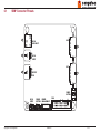
1
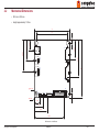
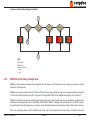
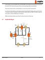
conga-SBM3
congatec Smart Battery Manager Module
User’s Guide
Revision 1.2
Revision History
Revision
Date (yyyy.mm.dd)
Author
Changes
1.0
1.1
2012.11.06
2013.07.22
AEM
AEM
1.2
2014.01.13
AEM
• Official release
• Updated section 4.1.1 “Bat Task (small battery task)
• Highlighted the essential registers used by ACPI control methods to determine the battery and information in section 7.3.1 “Control
Registers”
• Added cable description in section 7.2 “ Electrical Connections”
• Changed smart battery cell count resistors R96, R71 and R73 for revision X.1 to R99, R100 and R102 for revision A.x in section
5.1.1.1 “Input Voltage Threshold”.
• Updated sections 5.1.2.1 “Adapter Limiting” and 5.1.2.3 “Short-Circuit Protection”.
Copyright © 2012 congatec AG SBM3m12 2/57
Preface
This user’s guide provides information about the functions, firmware structure, customization and specifications of the conga-SBM3 module.
Disclaimer
The information contained within this user’s guide, including but not limited to any product specification, is subject to change without notice.
congatec AG provides no warranty with regard to this user’s guide or any other information contained herein and hereby expressly disclaims
any implied warranties of merchantability or fitness for any particular purpose with regard to any of the foregoing. congatec AG assumes
no liability for any damages incurred directly or indirectly from any technical or typographical errors or omissions contained herein or for
discrepancies between the product and the user’s guide. In no event shall congatec AG be liable for any incidental, consequential, special, or
exemplary damages, whether based on tort, contract or otherwise, arising out of or in connection with this user’s guide or any other information
contained herein or the use thereof.
Intended Audience
This user’s guide is intended for technically qualified personnel. It is not intended for general audiences.
Symbols
The following symbols are used in this user’s guide:
Warning
Warnings indicate conditions that, if not observed, can cause personal injury.
Caution
Cautions warn the user about how to prevent damage to hardware or loss of data.
Note
Notes call attention to important information that should be observed.
Copyright © 2012 congatec AG SBM3m12 3/57
Terminology
Term
Description
GB
GHz
kB
MB
Mbit
kHz
MHz
I2C bus
SMBus
I
CRC
PSU
O
PU
r
w
N.C.
N.A.
LDO
TBD
Gigabyte (1,073,741,824 bytes)
Gigahertz (one billion hertz)
Kilobyte (1024 bytes)
Megabyte (1,048,576 bytes)
Megabit (1,048,576 bits)
Kilohertz (one thousand hertz)
Megahertz (one million hertz)
Inter-Integrated Circuit Bus
System Management Bus
Input Signal
Cyclic Redundancy Code
Power Supply Unit
Output Signal
Pull Up Resistor
Read Operation
Write Operation
Not connected
Not available
Low dropout regulator
To be determined
Copyright Notice
Copyright © 2012, congatec AG. All rights reserved. All text, pictures and graphics are protected by copyrights. No copying is permitted without
written permission from congatec AG.
congatec AG has made every attempt to ensure that the information in this document is accurate yet the information contained within is
supplied “as-is
Copyright © 2012 congatec AG SBM3m12 4/57
Trademarks
Product names, logos, brands, and other trademarks featured or referred to within this user’s guide, or the congatec website, are the property
of their respective trademark holders. These trademark holders are not affiliated with congatec AG, our products, or our website.
Warranty
congatec AG makes no representation, warranty or guaranty, express or implied regarding the products except its standard form of limited
warranty (“Limited Warranty”) per the terms and conditions of the congatec entity, which the product is delivered from. These terms and
conditions can be downloaded from www.congatec.com. congatec AG may in its sole discretion modify its Limited Warranty at any time and
from time to time.
The products may include software. Use of the software is subject to the terms and conditions set out in the respective owner’s license
agreements, which are available at www.congatec.com and/or upon request.
Beginning on the date of shipment to its direct customer and continuing for the published warranty period, congatec AG represents that the
products are new and warrants that each product failing to function properly under normal use, due to a defect in materials or workmanship or
due to non conformance to the agreed upon specifications, will be repaired or exchanged, at congatec’s option and expense.
Customer will obtain a Return Material Authorization (“RMA”) number from congatec AG prior to returning the non conforming product freight
prepaid. congatec AG will pay for transporting the repaired or exchanged product to the customer.
Repaired, replaced or exchanged product will be warranted for the repair warranty period in effect as of the date the repaired, exchanged
or replaced product is shipped by congatec, or the remainder of the original warranty, whichever is longer. This Limited Warranty extends to
congatec’s direct customer only and is not assignable or transferable.
Except as set forth in writing in the Limited Warranty, congatec makes no performance representations, warranties, or guarantees, either
express or implied, oral or written, with respect to the products, including without limitation any implied warranty (a) of merchantability, (b) of
fitness for a particular purpose, or (c) arising from course of performance, course of dealing, or usage of trade.
congatec AG shall in no event be liable to the end user for collateral or consequential damages of any kind. congatec shall not otherwise be
liable for loss, damage or expense directly or indirectly arising from the use of the product or from any other cause. The sole and exclusive
remedy against congatec, whether a claim sound in contract, warranty, tort or any other legal theory, shall be repair or replacement of the
product only.
Copyright © 2012 congatec AG SBM3m12 5/57
Electrostatic Sensitive Device
All congatec AG products are electrostatic sensitive devices and are packaged accordingly. Do not open or handle a congatec AG product
except at an electrostatic‑free workstation. Additionally, do not ship or store congatec AG products near strong electrostatic, electromagnetic,
magnetic, or radioactive fields unless the device is contained within its original manufacturer’s packaging. Be aware that failure to comply with
these guidelines will void the congatec AG Limited Warranty.
Lead-Free Designs (RoHS)
All congatec AG designs are created from lead‑free components and are completely RoHS compliant.
Certification
ISO 9001
congatec AG is certified to DIN EN ISO 9001 standard.
C
ER
T I F I C AT I O
N
TM
Technical Support
congatec AG technicians and engineers are committed to providing the best possible technical support for our customers so that our products
can be easily used and implemented. We request that you first visit our website at www.congatec.com for the latest documentation, utilities and
drivers, which have been made available to assist you. If you still require assistance after visiting our website then contact our technical support
department by email at [email protected]
Copyright © 2012 congatec AG SBM3m12 6/57
Contents
1
General Information.................................................................. 10
1.1
1.2
1.3
1.4
1.5
Safety Instructions.................................................................... 10
Service and Maintenance......................................................... 10
Disposal Consideration............................................................. 11
Battery Kit Firmware Concept................................................... 11
conga-SBM3 Options Information.............................................. 11
2
Specifications............................................................................ 13
2.1
2.2
2.3
2.4
2.4.1
2.5
2.6
Feature List............................................................................... 13
Mechanical Dimensions............................................................ 16
Supported Operating Systems.................................................. 17
Supply Voltage Standard Power............................................... 17
Electrical Characteristics........................................................... 18
Output power rails..................................................................... 18
Environmental Specifications.................................................... 18
3
Block Diagram........................................................................... 19
4
Functional Descriptions............................................................. 20
4.1
4.1.1
4.1.2
4.1.3
4.1.4
4.1.5
4.1.6
4.1.7
4.2
4.2.1
4.2.2
4.2.3
4.2.4
4.2.5
4.2.6
4.2.7
4.2.8
Main Firmware Tasks................................................................ 21
BAT Task (smart battery task)................................................... 21
BTN Task (power button task)................................................... 22
LED Task (led on/off/blink functionality).................................... 22
SND Task (buzzer functionality)................................................ 22
CHR Task (charger task)........................................................... 23
SBM Task (smart battery manager task)................................... 26
Simplified State Diagram.......................................................... 27
Firmware Support Modules....................................................... 28
ADC Module (input voltage reading)......................................... 28
GPIO Module (GPIO support functions)................................... 28
PWR Module (handling of all power control signals)................ 28
SCH Module (preemptive multitasking scheduler).................... 29
SPI Module (SPI communication module)................................ 29
I2C1 Module (I2C communication module master/slave)......... 29
I2CS, I2CS1 Module (I2C communication module master/slave).30
Flash Module............................................................................ 30
4.2.9
4.2.10
Main Function........................................................................... 30
WDT Module............................................................................. 30
5
conga-SBM3 Customization...................................................... 31
5.1
5.1.1
5.1.1.1
5.1.1.2
5.1.2
5.1.2.1
5.1.2.2
5.1.2.3
5.2
5.2.1
5.2.1.1
5.2.1.2
5.2.1.3
34
5.2.1.4
Hardware Customization........................................................... 31
Voltage Adjustment................................................................... 31
Input Voltage Threshold............................................................ 31
LOPWR..................................................................................... 32
Current Adjustment................................................................... 32
Adapter Limiting........................................................................ 32
Maximum Charge Current......................................................... 32
Short-Circuit Protection............................................................. 33
Firmware Customization........................................................... 33
Voltage Adjustment................................................................... 33
Input Voltage Threshold............................................................ 33
Smart Battery Voltage and Current Limits................................. 34
Depleted Voltage and Current Change For Other Smart Batteries
6
Signal Descriptions and Pinout Tables...................................... 36
New Charge Current Calculation.............................................. 35
6.1SBM3 Connector Pinouts.......................................................... 37
6.1.1
JTAG Connector....................................................................... 38
6.1.2
DC-Input (+3V Li Battery)......................................................... 39
6.1.3
Power Button............................................................................ 39
6.1.4
Power Management Connector................................................ 40
6.1.5
DC-IN Jack Input....................................................................... 40
6.1.6
DC-IN Input............................................................................... 41
6.1.7
PSU Output............................................................................... 41
6.1.8
BAT1 Connector........................................................................ 42
6.1.9
BAT2 Connector........................................................................ 42
6.2
conga-SBM3 connections with congatec Boards...................... 43
6.2.1
conga-SBM3 connection with COM Express modules.............. 43
6.2.2
conga-SBM3 Connection with Qseven modules....................... 44
7
Interface Specification............................................................... 45
Copyright © 2012 congatec AG SBM3m12 7/57
7.1
7.2
7.2.1
7.2.1.1
7.2.1.2
7.2.1.3
7.2.2
7.2.2.1
7.2.2.2
7.3
7.3.1
7.3.2
Introduction............................................................................... 45
Electrical Connections.............................................................. 46
COM Express™ Electrical Connections..................................... 46
conga-SBM3 connection with CMCB mini-carrier board........... 47
conga-SBM3 connection with CEVAL Evaluation Board........... 48
conga-SBM3 connection with TEVAL Evaluation Board............ 49
QSeven™ Electrical Connections.............................................. 51
conga-SBM3 connection with QMCB mini-carrier board........... 52
conga-SBM3 connection with QEVA Evaluation Board............. 53
SBSM Control Register............................................................. 54
Control Registers...................................................................... 54
OptionalMfgCfgReg2 Register (0x3E)...................................... 56
8
Industry Specifications.............................................................. 57
Copyright © 2012 congatec AG SBM3m12 8/57
List of Tables
Table 1
Table 2
Table 3
Table 4
Table 5
Table 6
Table 7
Table 8
Table 9
Table 10
Table 11
Table 12
Firmware Feature Summary..................................................... 13
Hardware Feature Summary..................................................... 15
Electrical Characteristics Overview........................................... 18
Signal Tables Terminology Descriptions................................... 36
conga-SBM3 X4 Connector (Control Cable).............................. 43
conga-SBM3 X7 Connector (Power Cable)............................... 43
conga-SBM3 X4 Connector (Control Cable).............................. 44
conga-SBM3 X7 Connector (Power Cable)............................... 44
Signal Descriptions (COM Express Connection)...................... 46
Signal Descriptions (Qseven Connection)................................ 51
Control Register description...................................................... 54
Optional Register...................................................................... 56
Copyright © 2012 congatec AG SBM3m12 9/57
1
General Information
1.1
Safety Instructions
This safety guide provides important instructions that should be followed during the installation and maintenance of the conga-SBM3.
Precautions:
• Do not short the external contacts on a battery.
• Do not disassemble or deform the battery.
• Avoid exposing the battery to excessive shock or vibration.
• Do not use a degraded or damaged battery.
• Battery must be charged with approved charger only. Never use a modified or damaged charger.
• Keep out of reach of children.
• Do not leave batteries unused for extended periods of time, either in product or in storage. When the batteries have not been used for six
months, check the charge status and charge or dispose of the battery appropriately.
• Store in a cool, dry and well ventilated area. Refer to section 2.6 for operating and storage temperatures.
Warning
Incorrect handling of Li-Ion battery poses a safety hazard. Use caution when dealing with design areas that may adversely impact safety.
1.2
Service and Maintenance
Service, maintenance or repair of the conga-SBM3 must be performed by qualified and authorized service personnel only. Do not open or repair
the equipment on your own. Considerable danger may occur from unauthorized opening or improper repair of the conga-SBM3.
If there are service tasks required, contact your congatec sales representative.
Copyright © 2012 congatec AG SBM3m12 10/57
1.3
Disposal Consideration
The lithium-Ion batteries in the conga-SBM3 kit are subject to disposal and recycling regulations in various countries. Ensure that the applicable
regulations are followed before disposing of any battery.
Do not expose the battery to, or dispose of the battery in fire or water. Place only discharged batteries in a battery collection container. Use
electrical tape or other approved covering over the battery connection points to prevent short circuits.
1.4
Battery Kit Firmware Concept
The battery kit provides an interface between smart batteries and any computer platform according to the ACPI standard. This version of
battery kit is focused on Qseven and COM Express CPU modules.
A standardized library from the Cortex Microcontroller Software Interface Standard CMSIS Version 1.30 was used for programming the
conga-SBM3 and it is intended to be compliant with future MISRA programming language standards.
The firmware is based on preemptive multitasking. It is composed of tasks and supported modules. Tasks are scheduled to be executed in
given time frames and supported modules are used as drivers for all STM32 peripheries.
Note
Only 2.5’’ hard drives can be used when connecting conga-SBM3 to congatec mobility carrier boards. This is because the mobility carrier boards
do not provide +12V power rail. To use 3.5” hard drives, the +12V power rail must be directly connected to conga-SBM3 output.
1.5
conga-SBM3 Options Information
The conga-SBM3 is currently available in two variants. The input and output voltages are shown below:
Part-No.
025482 (2-cell battery)
Input Voltage
Output 1
Output 2
Norminal 19V/4.7A
+12V/3A
+5V/4A
+5Vsb/4A
+3.3V/0.25A
Smart Li-Ion Battery, 2-cells, 7.2V
Output 3
Supported Battery
Copyright © 2012 congatec AG SBM3m12 11/57
Part-No.
025483 (4-cell battery)
Input Voltage
Output 1
Output 2
Norminal 19V/4.7A
+12V/3A
+5V/4A
+5Vsb/4A
+3.3V/0.25A
Smart Li-Ion Battery, 4-cells, 14.4V
Output 3
Supported Battery
Note
The second output “Output 2” provides both +5V/4A and +5Vsb/4A output possibilities.
Copyright © 2012 congatec AG SBM3m12 12/57
2
Specifications
2.1
Feature List
Table 1
Firmware Feature Summary
The firmware is able to read the input voltage and then decide what additional steps to take, e.g due to charging limitations or other decisions
depending on DC-IN.
The device can not be switched on when less than 8V DC-IN is present. Over-voltage above 30 volts results in the LTC1960 automatically
switching off. In order to safely recover from this over-voltage protection state, all power must be removed from the conga-SBM3 battery kit.
All PSU Power Control All PSUs are switched on and off properly in all power states to avoid back powering, thereby ensuring proper power transitions.
Control signals to CPU module are open drain type to avoid back powering through signal lines.
3x Status LED for charger (PWRON, Line, Charge).
LED Signaling
5x Status LED for battery #1 (100%, 75%, 50%,25%,Empty).
5x Status LED for battery #2 (100%, 75%, 50%,25%,Empty).
3x LED for power rail status (+12V, +5V, +5Vsb).
Power button to manually switch on/off the device.
Power Button
Valid timing for button press events are:
1) Very short press (< 400 ms) : When in deep discharge protection mode with battery connected, the conga-SBM3 shows only the remaining
capacity of the battery on LEDs for about 2 seconds. The device then goes back to deep protection mode in order to save maximum battery
power. With a very short press, the device shows the battery status without switching on. This does not dissipate the battery.
2) Short press time (> 400 ms): To switch on/off the device (running from DC-IN or battery).
3) Long press (> 10 seconds): To force the device to switch off, irrespective of the state it is in. A clean transition to G2 mode occurs.
The onboard I2C temperature sensor. This can be read even if the CPU module is in sleep or in off mode. It can also be used to decide in severe
Temperature sensor
minus temperature, whether to continue to switch on the device or not. It is accessible from the CPU module via the I2C bus.
Dual / single phase smart battery charger support.
Battery charger
1) In sequential mode: The first battery can be considered as the main battery and the second one as a backup battery. In this mode, charging
and discharging must be provided separately because of the different battery cell capacity or charging current. The second battery (considered as
backup battery) is charged first.
2) Dual charging / discharging mode: Uses both smart batteries simultaneously for charging and discharging procedures. This mode does not
over stress the smart batteries with discharge currents, thereby extending the battery life and running time of PC (up to +20%) due to half-size
current taken from every battery in parallel mode.
DC-IN Voltage
Adapter Overload
Protection
Power Path Selector
Beeper
The charger has input adapter power overload protection. When full power is connected to the CPU module and carrier board, the charger helps
to reduce the input current by reducing the charge current, in order to protect DC-IN adapter overload.
Three sources of power input exist. These are:
• DC-IN,
• Smart battery 1 (main battery),
• Smart battery 2 (backup battery).
The firmware can fully control the power source where the device is powered from. For example during condition cycle, the power is taken from
the smart battery to provide full discharge and charge procedure even if the device is on DC-IN. When running on battery, the conga-SBM3 should
determine the battery that will supply power to the device.
A buzzer which can be used to signal either a switch on/off procedure or an error state. It can be used as longer tone sequences to distinguish the
various status of the device.
Copyright © 2012 congatec AG SBM3m12 13/57
Sleep Mode
Condition Cycle
The common sleep mode of any Qseven or COM Express module is supported by means of sensing of SUSC_S3# signal. The PWR_ON Led
blinks.
In sleep mode, the conga-SBM3 should monitor the remaining battery capacity. If low, the system must be in wake-up to enable the OS to save
open data files and properly switch off the device.
If any of the batteries require condition cycle, it means that the smart battery is internally confused about the amount of the remaining battery
capacity. To resolve this, an internal update of the smart battery is required. This is done by fully discharging the smart battery and subsequently
charging it fully. This procedure is only allowed when DC-IN is attached and the device is being powered by the battery.
The condition cycle is provided for every battery separately. Dual mode is not allowed. If DC-IN is removed, the device transitions into normal
battery powered mode. If DC-IN is reattached, then condition cycle restarts from the very beginning.
The only way to recover batteries that are depleted and in permanent protection mode with disabled output, is to set the charger into low current
Low current mode
mode with pulsed high voltage. This wakes up the smart battery from the protection mode. This procedure is possible only in single battery mode.
Dual mode is in this phase disabled.
By means of a special circuitry, the conga-SBM3 controller can switch off itself to prevent smart batteries that are connected in G2 mode for a long
Deep discharge
time without DC-IN (9 secs by default) from deep discharge.
protection
This timeout can be set in firmware to any value. After the timeout has elapsed, the conga-SBM3 is switched off totally. This protection state can
be seen when the LEDs indicating the remaining capacity of the batteries are off, even though the batteries are attached. This protection mode is
necessary e.g. to protect the batteries from discharging when the device is stored on stock for longer time periods without DC-IN.
The device can be switched on by pressing the power button. When the power button is pressed, the device powers itself and handles the power
button event in two ways:
1) Very short power button press < 400 ms: the device shows the remaining battery capacity status for a short time and then goes into protection
mode again
2) Standard button press > 400 ms: Switches the whole device on
Auto-start feature is not supported in this mode while DC-IN is not present.
If Power loss feature is set as “Turn On” in BIOS settings, the conga-SBM3 switches on the system as soon as the DC-IN power is present without
Autostart “Turn On”
any power button.
This feature is not supported by battery plug-in by default. This ensures that when the battery is plugged into a system that is not being powered,
the battery doesn’t automatically start powering the system, resulting in an immediate discharge. This feature can be supported if requested.
Configuration register Additional features such as enable/disable buzzer, dual charge/discharge can be enabled/disabled by writing into this register.
Registers 0x3E, 0x3F can be used for additional data/feature settings.
r/w at 0x3D
This data is stored in the last bank of STM32 flash memory.
NOTE:
Due to the limited write cycles of flash memory, it is not recommended to misuse these registers for storing constantly changing run-time data.
Copyright © 2012 congatec AG SBM3m12 14/57
Table 2
Hardware Feature Summary
Input / Output
Connector / Accessiblity
Power IN
Option 1: 8 Vdc - 30 Vdc, Nominal: 19V / 4,7A.
Option 2: 8Vdc - 30Vdc per external power connector / 10A.
ARM® 32-bit microcontroller STM32F100R8T6.
1x back/boost DC-DC regulator with output +12V / 3A.
1x back regulator with output +5V / 4A.
1x LDO +3,3V always.
3x status LED for charger (PWRON, Line, Charge).
5x status LED for battery #1 (100%, 75%, 50%,25%,Empty).
5x status LED for battery #2 (100%, 75%, 50%,25%,Empty).
3x LED for power rail status (+12V, +5V, +5Vsb).
1x power button (to switch on/off the device manually).
1x option: 2 pin connector for external power button switch.
1x on-board I2C temperature sensor.
2x standard smart battery (2S to 4S). By default, the conga‑SBM3 battery kit is developed for 2S (two serial
cells) smart batteries. For other cell counts (3S-4S), hardware and firmware modification is necessary to
adopt exact set levels for the particular battery pack.
Both smart batteries (Bat1 and Bat2) must always have the same cell count. The batteries are also directly
connected to battery manager controller.
CPU / Microcontroller
PSU
LED Signalling
Power Button
Temperature Sensor
Battery
Battery Charger
Power Path Selector
Beeper
Reverse Input Voltage Protection
Connectivity
NOTE:
You cannot use two batteries of varying cell count simultaneously.
1x dual/single phase smart battery charger with maximum charging current of 4A and input power overload
protection.
1x fast power path selector as part of LTC1960.
Three sources of power inputs :
• DC-IN
• Smart battery 1 (main battery)
• Smart battery 2 (backup battery).
1x buzzer to signal switch on/off and fault states.
Protection against unwanted reverse input voltage connection.
Option 1:- for Qseven platform (QMCB / QEVA cabling conversion).
Option 2:- for COM Express platform (CMCB / CEVA cabling conversion [PSU +12V, +5V and +5Vsb
power rails supported only]).
Option 3:- customized wiring (T.B.D).
Caution
Do not connect smart batteries that are not 2S (2 serial cell) to the conga-SBM3 battery kit. This could damage the hardware or the batteries.
conga-SBM3 battery kit is developed by default for 2S smart batteries. For the support of a different cell count other than 2S, the hardware and
software must be modified to appropriate voltage level and parameters.
Copyright © 2012 congatec AG SBM3m12 15/57
2.2
Mechanical Dimensions
• 90.0 mm x 80.0 mm
• Height approximately 13.7mm.
90
X5
80
X7
51.67
X6
44.42
28.88
X9
26.85
15.8
5
80
X8
O 3.2 (4x)
X1
L3
X2
X4
5
X3
R3 (4x)
12.53
22.13
31.73
75.74
All dimensions in millimeter
Copyright © 2012 congatec AG SBM3m12 16/57
2.3
Supported Operating Systems
The conga-SBM3 supports the following operating systems.
• Microsoft® Windows® 7
• Microsoft® Windows® XP
• Microsoft® Windows® Embedded Standard
• Linux
2.4
Supply Voltage Standard Power
• Wide input voltage range 8 - 30 Vdc
• Norminal 19V DC
The dynamic range shall not exceed the absolute minimum and maximum range (static range).
Absolute Maximum
30.00Vdc
Dynamic Range
19.10Vdc
19Vdc
Nominal
Static Range
18.90Vdc
8.00Vdc
Absolute Minimum
Copyright © 2012 congatec AG SBM3m12 17/57
2.4.1
Electrical Characteristics
Table 3
Electrical Characteristics Overview
The following table provides an overview of the conga-SBM3 electrical characteristics.
INPUT
Voltage range
Tolerance
Max. current
Ripple voltage
Power
2.5
AC- Adapter
19V nom.
Battery
2S - 4S
8 - 30 V
±10%
4.7A / 19V
89W
6 - 16,8V
*lbat max. allowed
*lbat max. allowed
OUTPUT
12V
5V / +5Vsb
Charger
11.4 - 12.6V
±5%
4A
170mV
48W
4.75 - 5.25V
±5%
4A
60mV
20W
6 - 16.8V
4A (could be increased)
200mV
67W *(adapter over-current protection functionality activated).
Output power rails
• +12V
• +5V
• +5Vsb
2.6
Environmental Specifications
Temperature
Operation: 0° to 60°C
Storage: -20° to +80°C
Humidity
Operation: 10% to 90%
Storage: 5% to 95%
Caution
The above operating temperatures must be strictly adhered to at all times. Humidity specifications are for non-condensing conditions.
It is the responsibility of the operator to ensure that all components found on the module operate within the component manufacturer’s specified
temperature range.
Ensure adequate air flow when operating conga-SBM3 in an enclosed space.
Copyright © 2012 congatec AG SBM3m12 18/57
3
Block Diagram
Power Button
MicroController
I²C / SMB
I²C / SMB
I²C, BAT_LOW#, PS_ON, PWR_BTN, S5
12V
Converter
Charger
Switch
12 Volt
SMART
Charger
5 Volt
Power MUX
Reverse
Voltage
Protection
SMART
Battery
#1
SMART
Battery
#2
..
..
5V
Converter
SBM³
Standby
Application
OS
ACPI CGOS
CMB
congatec
Board
Controller
Computer-On-Module
Carrier Board
DC Input 8-30V
=
~
AC/DC
110V AC
230V AC
Copyright © 2012 congatec AG SBM3m12 19/57
4
Functional Descriptions
Functional Block Diagram
DC-IN
adc
Selector
Charger
BAT 1
BAT 2
I2CS1
master
I2CS2
master
spi
bat 1
50 ms
bat 2
50 ms
chr
50 ms
SBM3
CPU
Module
I2C1
sbm
sch
gpio
snd
2 ms
master/slave
btn
50 ms
led
500 ms
KEY
Driver
Module
Task
Copyright © 2012 congatec AG SBM3m12 20/57
4.1
Main Firmware Tasks
4.1.1
BAT Task (smart battery task)
Battery task runs autonomously using only particular drivers such as I2C bus as interfaces. Every smart battery has its own “bat task” called
BAT1task() and BAT2task().
Battery task periodically checks if the battery is connected. This is done by means of a simple access reading and waiting for acknowledgment.
This state is called BAT_NOT_PRESENT. The reading period for connection can be different from the interval used for fast read out phase.
BAT tasks for batteries are split into two because if one smart battery is connected, the second one can be removed. This means that the timing
interval can also be different at different times.
If the smart battery is connected and does respond, the smart battery is fully read out as fast as possible. This ensures that the operating
system is quickly aware that a new battery is present. This state is called BAT_PLUGGED.
Later on, only a group of dynamic registers of the smart battery are read, because the rest of the registers are constant. This state is called
BAT_VALIDATED. If the battery is removed, the BAT task starts with checking the connection reading again.
Data transfer uses cyclic redundancy check (CRC) to accept only trusted data received from the smart battery.
To report run-time data changes from the battery eg. remaining capacity value change, a special interrupt signal BATLOW# is used.
The BAT task changes are handled in a special way, so that if a sudden change is noticed at any address position, the status bit
BAT_STATUS_BAT_DATA_CHANGED is set. BAT task will continue to read the rest of the registers that may be changed by this internal
update of the smart battery.
After the reading of all the remaining registers, the status bit BAT_STATUS_BAT_CHANGES_FINISHED is set. SBM task then sends the
BATLOW# interrupt signal to the CPU module in order to indicate a change in the battery manager. This results in an ACPI update request
being sent to the operating system.
The gBATdata structure keeps all the data context to be used by other tasks.
Copyright © 2012 congatec AG SBM3m12 21/57
4.1.2
BTN Task (power button task)
BTN task runs autonomously, reading the power button in intervals of 50ms. The duration of button-press is measured and evaluated for two
possible reactions:
• If the power button is pressed longer than BTN_SHORT_TIME_DELAY time constant, gBTNdata.ShortPressActivated is set to 1 and the
system either switches on or off, depending on the current state.
• If the power button is pressed even longer, with a time equal to or greater than BTN_LONG_TIME_DELAY time constant, it is considered
as a long press. This forces the system to switch off immediately and the variable gBTNdata.LongPressActivated is set to 1. This is similar
to ATX long press behavior.
The gBTNdata structure keeps all the data context to be used by other tasks.
4.1.3
LED Task (led on/off/blink functionality)
LED task provides a handling of all LED modes, including all support functions to drive LED high or low in single or in group mode. This task
can be used for timed actions on LED and for additional functionality such as blinking if necessary.
4.1.4
SND Task (buzzer functionality)
SND task provides a handling for the buzzer. Several tones are defined in an array SND_TONES_ARRAY[] and any of them can be played.
It is possible to signal the status of the battery mode efficiently by playing more tones. For example, the tones can sound higher during switch
on or lower when switching off.
The adoption of the sound array provides this functionality with various sound options. Each error can be set with a specific tone, to indicate
the nature of the problem.
Copyright © 2012 congatec AG SBM3m12 22/57
4.1.5
CHR Task (charger task)
CHR task provides full handling of the selector and charger IC LTC1960. This task is set to 400ms execution period.
Charger functionality:
The charger is a state machine that must handle the smart batteries properly. The main functionality is to charge the smart batteries in parallel
or in sequential mode. In sequential mode, the charging priority of the batteries can be set. By default, the second battery (considered as a
backup) has to be charged first and discharged last.
If two dissimilar batteries are connected, the supported dual charger mode prevents the smart battery with the lower voltage capacity from
over‑current. The smart battery with lower voltage takes more current and must be read periodically. This adjusts the dual charging current
so that it is not acting as 2x single charge. Dual charging current is dynamically calculated and stored in a variable gCHRdata.uiDualCurrent.
Its value changes to the maximum value allowed by the smart battery with lower voltage. An optimal case would be to have two similar smart
batteries with same or very close parameters.
The charger supports low current mode in order to recover a depleted smart battery from its protection mode. In this mode, the smart battery
is internally switched off and needs a special procedure for the recovery. Another support offered by the charger is the condition cycle, if it
is requested from the smart battery. In this case, the smart battery has lost track of the state of the cell chemistry. This means that the smart
battery will not be able to estimate the remaining capacity or it will report a false remaining capacity.
Commands to the charger are sent per SPI commands where the returned data are always checked for validity; otherwise the command will
be sent again. There is a mechanism to update the charger with only the data that has been changed. The exception is a periodic command
CHRupdateCharger() used when charging the batteries. This must be used to keep the charger working, otherwise its safety mechanism will be
activated after a certain timeout and the charging will stop. The charger task will analyze the charge requests from batteries, with their voltage
and current requirements and then will decide on the amount of current necessary to protect the maximum power dissipation of the battery
charging system.
The “Rsense” resistor value in the charger circuitry is used for calculating the charging current. In the firmware, the value CHR_RSENSE_RESISTOR
must be updated if the Rsense resistor changes in hardware.
The maximum charge voltage is given by CHR_BATn_CHARGE_VOLTAGE_MAX and the currents by CHR_BATn_CHARGE_CURRENT_MAX.
Copyright © 2012 congatec AG SBM3m12 23/57
Condition Cycle Block Diagram (simplified)
S
CC B1 ?
+
-
Dis
+
Dis B1
-
Chr B1
CC B2 ?
+
Dis
+
Dis B2
-
-
Chr B2
KEY
E
B1= Battery 1
B2= Battery 2
CC= Condition cycle
Dis= Discharge
S= Start
E= End
Copyright © 2012 congatec AG SBM3m12 24/57
Charge Block Diagram (simplified)
S
Chr B1 ?
+
Set U
LC ?
+
Set I
LC mode
Set I
Chr B1
Chr B2 ?
+
Set U
LC ?
Set I
LC mode
Disable B1
+
-
II charge
-
Set 1
Chr B2 only
+
I1 + I2
Limit
B1 + B2
Charge
KEY
B1= Battery 1
B2= Battery 2
LC= Low current
S= Start
E= End
E
Copyright © 2012 congatec AG SBM3m12 25/57
Running-on-batteries Block Diagram (simplified)
S
+
B2
B2 ?
-
B1 ?
+
B2 ?
+
II Mode
-
-
B1
B1
+
II Mode
Off
E
KEY
B1= Battery 1
B2= Battery 2
II Mode= Dual mode
S= Start
E= End
4.1.6
SBM Task (smart battery manager task)
SBM task is the main power management task responsible for all the power on and off sequences, such as power supply switch-on and the
handling of all control signals.
SBM task ensures proper communication via I2C slave to CPU module. Any change of batteries, power sources, charging states etc. is signaled
to CPU module with the interrupt line via I2C bus by means of the signal BATLOW#. For the simplified state diagram, refer to section 4.1.7.
SBM task provides the deep discharge protection functionality so that when in G2 mode (Off mode) and only the batteries are attached, the
batteries are not discharged. After a time out SB_DEEP_DISCHARGED_TIMEOUT, it switches off the whole battery kit. The STM32 controller
also switches off so that a stock laying device, for example, will not discharge batteries anymore thereby extending its lifetime to the maximum.
With a very short power button press, the SBM task will quickly read out the registers from the smart battery. The LEDs will show the
Copyright © 2012 congatec AG SBM3m12 26/57
remaining capacity for a short time SB_DEEP_DISCH_LED_SHOW_TIMEOUT, and immediately enter the deep protection mode again. After
the connection of DC-IN, the device will be powered all the time and the deep discharge protection mode will be disabled.
Firmware revision is stated in the sbm.h under SBM_FW_REV_NO. It can be read out later via I2C from address 0x3C.
Turn-on after power loss functionality is executed during the powering of the device from DC-IN. The battery controller goes from G2 mode to
G1 mode shortly, to switch the +5Vsb voltage on to the CPU module for a time SBM__REMAIN_ON_TIMEOUT. If this feature is activated, the
device will switch on, otherwise the SBM task goes into G2 state again.
SBM task checks batteries and initiates a power off event if the device is turned on but out of battery power.
4.1.7
Simplified State Diagram
AutoOn
PWRBTN#
SUSC_S3#
PWRBTN#
BAT empty
5Vsb ON
G2_G1
PSU PG
TimeOut
12V, 5V ON
G2_G0
G1
PSU PG
TimeOut
PSU PG
TimeOut
DCIN
G0
G2
G3
Deep disch
protection
12V, 5V OFF
SUSC_S5# High
PWRBTN#
BAT empty
RemainCap Alarm
SUSC_S3# Low
G1_G2
SUSC_S5# Low
G1_G0
All PSU off
Copyright © 2012 congatec AG SBM3m12 27/57
4.2
Firmware Support Modules
4.2.1
ADC Module (input voltage reading)
ADC module is used to periodically read the input voltage of the battery kit, in order to adopt charging behavior accordingly. Periodic reading
is set by using DMA controller. This immediately copies converted ADC values to gADCdata.uiADCConvertedValue variable as soon as ADC
convertor is finished. An additional function to calculate the absolute value that represents the voltage value, is called ADCcalculateInputVoltage().
This function must be called additionally as soon as the absolute value of the voltage representation is needed, shortly before its evaluation.
Parameter holding the current voltage value is gADCdata.uiInputVoltage in a format :100.
For example, value=1956 means 19,56V.
Note
Reaction on input voltage value can be additionally handled e.g to reduce charging current and prevent heating up of the device if the system
is in S0 running mode. Recommended place for this input voltage consideration is in the charger module (CHR module), where an action must
be decided if the input voltage changes.
Very low input voltage value or very high protection is already handled in the hardware by IC selector/charger settings, which immediately
disables charging and provides prevention against input voltage if it is out of limit.
4.2.2
GPIO Module (GPIO support functions)
GPIO module is used to set up GPIO pins to certain functions like input, output, alternative function etc.
4.2.3
PWR Module (handling of all power control signals)
PWR module provides a group of functions to handle all control signals for all power supply circuits on the battery kit device. Every PSU can
be switched on or off as necessary in every power state of the battery manager.
Switch on +12V PSU command is e.g. PWRpinOutOn(PWR_VR12V_EN) etc.
Note
There is also a special debug feature in PWR module to help tune and check power supply circuitry. If power button is pressed during the
power-up of the device, the power debug feature will be activated by enabling PWR_ALL_POWER_ON. The firmware will then enable all PSUs
on the device and will enter an endless loop, to help in testing and measuring. Do not forget to disable it for serial production.
Copyright © 2012 congatec AG SBM3m12 28/57
BATLOW# signal must be configured as open drain always. This is used on some Intel® platforms to prevent the system from switching on
automatically. It can be forced low from CPU module side.
4.2.4
SCH Module (preemptive multitasking scheduler)
SCH module includes all necessary functionality of the firmware for implementing a preemptive multitasking core. The following seven tasks
are used for this battery kit implementation:
• SCH_TASK_0 (LEDtask()) - LED timing handling task
• SCH_TASK_1 (BTNtask()) - Power button timed handling task
• SCH_TASK_2 (SNDtask()) - Sound task managing tones and its sequences
• SCH_TASK_3 (CHRtask()) - Charger and selector task for battery care
• SCH_TASK_4 (BAT1task()) - Run-time read out task for battery 1
• SCH_TASK_5 (BAT2task()) - Run-time read out task for battery 2
• SCH_TASK_6 (SBMtask()) - Main battery manager functionality
4.2.5
SPI Module (SPI communication module)
SPI module is a driver that provides a mechanism for SPI communication with a selector and charger IC. The SPI transfer is interrupt handled.
Requests for output transfer and read out returned data are handled with a special locking mechanism to ensure that the data returned will be
read only by the same function that initiated that particular SPI data transfer.
4.2.6
I2C1 Module (I2C communication module master/slave)
I2C1 module is a driver that provides a mechanism for I2C communication with a host CPU module and slaves itself on the battery kit such as
with an EEPROM and temperature sensor. It includes both master and slave functionality .
Requests for master transfers and returned data are handled with a special locking mechanism to ensure that the data returned will be read
only by the same function that initiated that particular I2C data transfer.
Copyright © 2012 congatec AG SBM3m12 29/57
4.2.7
I2CS, I2CS1 Module (I2C communication module master/slave)
Both I2CS and I2CS1 modules are I2C software polled drivers for the connection of both batteries. Both support Packet Error Check (PEC)
and CRC correction. This should be enabled to receive and accept only valid data from the I2C bus. BAT1 uses I2CS1 driver and BAT2 uses
I2CS driver.
4.2.8
Flash Module
FLASH module handles configuration data for the battery kit. Configuration data can be read via I2C to CPU module from
OP_SMB_CFG1 – OP_SMB_CFG3 registers. Writing new configuration data to the OP_SMB_CFG1 register will start executing the flash
writing cycle. Internal flash memory of STM32 ARM controller is used to store config data. After the start of the battery kit, all configuration data
are read from flash and used as start up default values for all dedicated values. Flash write cycles are limited. Therefore, it is not recommended
to write or change the config data frequently.
4.2.9
Main Function
Main function provides the initialization of all modules, NVIC interrupt table settings and all proper task execution as set in SCH module.
4.2.10
WDT Module
WDT module includes init, reset and stop functions for WDT functionality used in the conga-SBM3 battery kit. By default, a timeout of three
seconds is set. The STM32 controller is reset after exceeding the timeout.
Copyright © 2012 congatec AG SBM3m12 30/57
5
conga-SBM3 Customization
5.1
Hardware Customization
Microcontroller: ARM based 32 bit. P/N: STM32F100R8T6B
Debugging tools: Hitex Cortino jtag debugger, which includes Hitex IDE with GNU compiler and linker toolchain.
For efficient programming and debugging of the conga-SBM3, congatec AG recommends that the customer should:
• Buy the original Hitex programmer for ARM32b Cortex Applications.
• Install the enclosed software including HiTOP version 5.4 or higher. Choose the GNU compiler and provide the necessary software registration
in accordance to the software guideline.
• Start Hitop after a successful installation. This is done by double-clicking the HiTOP icon
“Start-> Programs -> HiTP54-Cortino”
on the desktop or alternatively by clicking
• Open the conga-SBM3 project file “SBM3.htp” from the source directory by clicking the “Project-> Open” Menu.
• Start the firmware by clicking “Run ->Go” or by pressing key “F5”.
5.1.1
Voltage Adjustment
5.1.1.1
Input Voltage Threshold
If the voltage at DCDIV is above the DCDIV comparator threshold 1.19V, then the DC bit is set and the wall adapter power is considered to be
adequate to charge the batteries. If DCDIV rises more than 1.8V above VCC, then all of the power-path switches are latched off until all power
is removed.
Smart Battery Cell Count
[N]
R99
[kOhm]
R100
[kOhm]
R102
[kOhm]
Input Voltage Range for charging
[V]
2S
3S
4S
3.90
3.90
8.20
24.00
8.20
8.20
4.02
1.20
1.20
9.40 - 30.00
13.60 - 30.00
17.80 - 30.00
Copyright © 2012 congatec AG SBM3m12 31/57
5.1.1.2
LOPWR
If the voltage at LOPWR is lower than the LOPWR comparator threshold 1.19V, then the system power has failed and power is autonomously
switched to a higher voltage source, if available.
Smart Battery Cell Count
[N]
R103
[kOhm]
R104
[kOhm]
2S
3S
4S
820.00
820.00
820.00
210.00
127.00
93.10
5.1.2
Current Adjustment
5.1.2.1
Adapter Limiting
R93 monitors and limits the input current, to protect the wall adapter. If input current is higher than set, the charger decreases the charge
current so that batteries can keep input current under limit.
5.1.2.2
R93
[mOhm]
Input Current Limit
[A]
21.3
16.7
10.0
4.7
6.0
10.0
Maximum Charge Current
Charging current is sensed on sense resistor R106. If dual charging is used, both BAT1 and BAT2 currents must be added to calculate R106.
R106
[mOhm]
Charge Current
[A]
25.0
20.0
12.0
10.0
4.1
5.1
8.2
10.2
Note
Do not forget to also reflect the proper value of R106 in firmware header file “chr.h” as shown below:
Copyright © 2012 congatec AG SBM3m12 32/57
#define CHR_RSENSE_RESISTOR 15 where 15 is the 15mOhm sense resistor used for current calculation.
5.1.2.3
Short-Circuit Protection
Output current to device supplied by conga-SBM3 is sensed on sense resistor R97. If the device draws higher current than set by R97, then all
of the power-path switches are turned off and the FAULT bit (FA) is set.
R97
[mOhm]
Short Current Protection
[A]
100.0
50
25.0
15.0
12.0
1.02
2.05
4.09
4.65
8.18
Note
Make sure that this does not occur in normal running state, during switch on/off or between sleep mode transitions. This should be used only
as a protective circuit:
5.2
Firmware Customization
5.2.1
Voltage Adjustment
5.2.1.1
Input Voltage Threshold
The input voltage thresholds for minimal and maximal voltages are defined in the following macros. The device will only work within the range
specified in header file “sbm.h” as shown below:
Macros in module “sbm.h”
#define SBM_DCIN_MIN_LIMIT 750
/* min input voltage for enabling device function in 10mV units */
#define SBM_DCIN_MAX_LIMIT 3050
/* min input voltage for enabling device function in 10mV units */
Copyright © 2012 congatec AG SBM3m12 33/57
5.2.1.2
Smart Battery Voltage and Current Limits
The minimum or maximum voltage and current limits for every cell count of smart battery are defined in the following macros in header file
“chr.h”:
Macros in module “chr.h”
#define CHR_BAT1_CHARGE_CURRENT_MAX 4000
/* Max current allowed by hardware */
#define CHR_BAT1_CHARGE_VOLTAGE_MAX 8400
/* Max voltage allowed, depends on cell count 4.2V / 1S */
#define CHR_BAT2_CHARGE_CURRENT_MAX 4000
/* Max current allowed by hardware */
#define CHR_BAT2_CHARGE_VOLTAGE_MAX 8400
/* Max voltage allowed, depends on cell count 4.2V / 1S */
Recommended limits for common Li-ion smart batteries are stated below:
Smart Batttery Cell Count
[N]
Macro Name
Voltage
[mV]
2S
3S
4S
CHR_BATn_CHARGE_VOLTAGE_MAX
CHR_BATn_CHARGE_VOLTAGE_MAX
CHR_BATn_CHARGE_VOLTAGE_MAX
8400
12600
16800
Note
All parameters of non standard smart batteries used in the conga-SBM3 battery kit must be properly set in all the firmware parameters in the
header files. All above values are based on 3.7Vnom/cell with max. voltage 4.2V/cell. All other parameters must be properly recalculated:
5.2.1.3
Depleted Voltage and Current Change For Other Smart Batteries
Voltage and current settings for depleted batteries procedure should be adjusted as shown below:
Macros in module “chr.h”
#define CHR_CHARGE_LC_DEPLETED_VOLTAGE 16600
/* Higher voltage used for depleted batteries at low depleted current [10mV unites]*/
#define CHR_CHARGE_LC_DEPLETED_CURRENT 2100
/* Low current used for depleted batteries [mA/8] */
Copyright © 2012 congatec AG SBM3m12 34/57
Recommended limits for common Li-ion smart batteries are stated below:
5.2.1.4
Smart Batttery Cell Count
[N]
Macro Name
Voltage
[mV]
2S
3S
4S
CHR_CHARGE_LC_DEPLETED_VOLTAGE
CHR_CHARGE_LC_DEPLETED_VOLTAGE
CHR_CHARGE_LC_DEPLETED_VOLTAGE
8600
12800
17200
New Charge Current Calculation
After hardware change of R106, the following firmware change is necessary:
Macros in module “chr.h”
#define CHR_RSENSE_RESISTOR 15
/* 15mOhm sense resistor used for current calculation!*/
Copyright © 2012 congatec AG SBM3m12 35/57
6
Signal Descriptions and Pinout Tables
The following section describes the signals found on the conga-SBM3. This table describes the terminology used in this section for the Signal
Description tables.
The PU/PD column indicates if an internal pull-up or pull-down resistor has been used on the conga-SBM3, if the field entry area in this column
for the signal is empty, then no pull-up or pull-down resistor has been implemented.
The “#” symbol at the end of the signal name indicates that the active or asserted state occurs when the signal is at a low voltage level. When
“#” is not present, the signal is asserted when at a high voltage level.
Note
The Signal Description tables do not list internal pull-ups or pull-downs implemented by the chip vendors, only pull-ups or pull-downs implemented
by congatec are listed. For information about the internal pull-ups or pull-downs implemented by the chip vendors, refer to the respective chip’s
datasheet.
Table 4
Signal Tables Terminology Descriptions
Term
Description
PU
PD
I/O 3.3V
I/O 5V
I 3.3V
I 5V
I/O 3.3VSB
O 3.3V
O 5V
OD
P
congatec implemented pull-up resistor
congatec implemented pull-down resistor
Bi-directional signal 3.3V tolerant
Bi-directional signal 5V tolerant
Input 3.3V tolerant
Input 5V tolerant
Input 3.3V tolerant active in standby state
Output 3.3V signal level
Output 5V signal level
Open drain output
Power Input/Output
Copyright © 2012 congatec AG SBM3m12 36/57
SBM3 Connector Pinouts
X9
X5
6.1
BAT2
X6
DC-IN
JACK INPUT
DC-IN
INPUT
X7
BAT1
OUTPUT
PSU
X8
DC-IN
INPUT
X2
POWER
BUTTON
X3
JTAG
POWER
MANAGEMENT
POWER
BUTTON
M5
X4
X1
Copyright © 2012 congatec AG SBM3m12 37/57
6.1.1
JTAG Connector
X1
19
17
15
13
11
9
7
5
3
1
20
18
16
14
12
10
8
6
4
2
Pin
Signal
Description
Input / Output PU/PD
1
2
3
4
5
6
7
8
9
10
11
12
13
14
15
16
17
18
19
20
V_3V_ALW
V_3V_ALW
JTAG_nJRST
GND
JTAG_TDI
GND
JTAG_TMS
GND
JTAG_TCK
GND
JTAG11
GND
JTAG_TDO
GND
CPU_nRST
GND
JTAG17
GND
JTAG19
GND
VCC
VCC
JTAG Interface
GND
JTAG Interface
GND
JTAG Interface
GND
JTAG Interface
GND
JTAG Interface
GND
JTAG Interface
GND
CPU Reset
GND
JTAG Interface
GND
JTAG Interface
GND
P
P
I/O 3V3
P
I/O 3V3
P
I/O 3V3
P
I/O 3V3
P
I/O 3V3
P
I/O 3V3
P
I/O 3V3
P
I/O 3V3
P
I/O 3V3
P
Copyright © 2012 congatec AG SBM3m12 38/57
6.1.2
DC-Input (+3V Li Battery)
1
6.1.3
2
X2
Pin
Signal
Description
Input / Output
1
2
VBAT_IC
GND
VCC batt
GND
P
P
PU/PD
Power Button
1
2
X3
Pin
Signal
Description
Input / Output
1
2
BAT12D
BAT12DS
external PWR Btn
external PWR Btn
I/O
I/O
PU/PD
Copyright © 2012 congatec AG SBM3m12 39/57
6.1.4
Power Management Connector
1
6.1.5
2
3
4
5
6
7
8
9
X4
10
Pin
Signal
Description
Input / Output
1
2
3
4
5
6
7
8
9
10
SUSC_S5#
SUSC_S3#
SUSC_STAT#
CPU_SDA
CPU_SCL
BAT_LOW
PWR_BTN_CPU#
CPU_RESET#
PWR_OK
GND
S5 request
S3 Sleep request
Sleep request
I2C data line
I2C clock line
I2C interrupt line
Power button signal to CPU module
Reset to CPU module
Power OK signal to CPU module
GND
I 3V3, FT
I 3V3, FT
I 3V3, FT
I/O 3V3, FT
I/O 3V3, FT
OC, 3V3, FT
OC, 3V3, FT
OC, 3V3, FT
OC, 3V3, FT
P
DC-IN Jack Input
PU/PD
X5
6
3
2
1
4
5
Pin
Signal
Description
Input / Output
1
2
3
4
5
6
DC_IN_CON
N.C.
GND
GND
GND
GND
DC input
N.C.
GND
GND
GND
GND
P
N.C.
P
P
P
P
PU/PD
Copyright © 2012 congatec AG SBM3m12 40/57
6.1.6
DC-IN Input
X6
2
4
1
3
6.1.7
Pin
Signal
Description
Input / Output
1
2
3
4
DC_IN_CON
DC_IN_CON
GND
GND
DC input
DC input
GND
GND
P
P
P
P
PSU Output
PU/PD
X7
3
6
2
5
1
4
Pin
Signal
Description
Input / Output
1
2
3
4
5
6
GND
GND
V_5V_SB
V_5V
V_12V
V_12V
GND
GND
VCC 5V SB output
VCC 5V output
VCC 12V output
VCC 12V output
P
P
P
P
P
P
PU/PD
Copyright © 2012 congatec AG SBM3m12 41/57
BAT1 Connector
X8
5
4
3
2
1
6.1.8
6.1.9
Pin
Signal
Description
Input / Output PU/PD
1
2
3
4
5
B1SCLK
B1SDAC
TB1
GND
U_BAT1
SMB clock
SMB data
TERM
GND
VBAT
I/O 3V3
I/O 3V3
I
P
P
PU 10k V_3V3_ALW
PU 10k V_3V3_ALW
PD 0Ohm
BAT2 Connector
5
4
3
2
1
X9
Pin
Signal
Description
Input / Output PU/PD
1
2
3
4
5
B2SCLK
B2SDAC
TB2
GND
U_BAT2
SMB clock
SMB data
TERM
GND
VBAT
I/O 3V3
I/O 3V3
I
P
P
PU 10k V_3V3_ALW
PU 10k V_3V3_ALW
PD 0Ohm
Copyright © 2012 congatec AG SBM3m12 42/57
6.2
conga-SBM3 connections with congatec Boards
6.2.1
conga-SBM3 connection with COM Express modules
Table 5
conga-SBM3 X4 Connector (Control Cable)
conga-SBM3
(X4 Connector)
Pin
Signal
1
2
3
4
5
6
7
8
9
10
SUSC_S5#
SUSC_S3#
SUSC_STAT#
CPU_SDA
CPU_SCL
BAT_LOW
PWR_BTN_CPU#
CPU_RESET#
PWR_OK
GND
Table 6
7
6
5
2
3
4
8
nc
nc
1
SUS_S5#
SUS_S3#
SUS_STAT
SDA
SCL
BATLOW#
PWRBTN#
nc
nc
GND
conga-CEVAL
(X27 Connector)
Pin
Signal
26
15
23
5
7
31
39
36
40
17
SUS_S5#
SUS_S3#
SUS_STAT
I2DAT
I2CLK
BATLOW#
PWRBTN#
SYS_RESET#
PWR_OK
GND
conga-TEVAL
(X53 Connector)
Pin
Signal
26
15
23
5
7
31
39
36
40
17
SUS_S5#
SUS_S3#
SUSC_STAT
I2DAT
I2CLK
BATLOW#
PWRBTN#
SYS_RESET#
PWR_OK
GND
Description
S5 request
S3 Sleep request
Sleep request
I2C data line
I2C clock line
I2C interrupt line
Power button signal to CPU module
Reset to CPU module
Power OK signal to CPU module
GND
conga-SBM3 X7 Connector (Power Cable)
conga-SBM3
(X7 Connector)
Pin
Signal
1
2
3
4
5
6
conga-CMCB
(X20 Connector)
Pin
Signal
GND
GND
V_5V_SB
V_5V
V_12V
V_12V
conga-CMCB
(X19 Connector)
Pin
Signal
3
4
5
NC
1
2
GND
GND
+5V STB
NC
+12V
+12V
conga-CEVAL
(X70 Connector)
Pin
Signal
3
5
9
4
10
NC
GND
GND
+5V SB
+5V
+12V
NC
conga-TEVAL
(X59 Connector)
Pin
Signal
3
5
9
4
10
NC
GND
GND
5V_SB
+5V
+12V
NC
Description
GND
GND
VCC 5V SB output
VCC 5V output
VCC 12V output
VCC 12V output
Copyright © 2012 congatec AG SBM3m12 43/57
6.2.2
conga-SBM3 Connection with Qseven modules
Table 7
conga-SBM3 X4 Connector (Control Cable)
conga-SBM3
(X4 Connector)
Pin
Signal
1
2
3
4
5
6
7
8
9
10
SUSC_S5#
SUSC_S3#
SUSC_STAT#
CPU_SDA
CPU_SCL
BAT_LOW
PWR_BTN_CPU#
CPU_RESET#
PWR_OK
GND
Table 8
7
6
5
2
3
4
8
NC
NC
1
SUS_S5#
SUS_S3#
SUS_STAT
SDA
SCL
BATLOW#
PWRBTN#
NC
NC
GND
conga-QEVA
(CN35 Connector)
Pin
Signal
26
15
23
5
7
31
39
36
40
17
SUS_S5#
SUS_S3#
SUS_STAT
I2DAT
I2CLK
BATLOW#
PWRBTN#
SYS_RESET#
PWR_OK
GND
Description
S5 request
S3 Sleep request
Sleep request
I2C data line
I2C clock line
I2C interrupt line
Power button signal to CPU module
Reset to CPU module
Power OK signal to CPU module
GND
conga-SBM3 X7 Connector (Power Cable)
conga-SBM3
(X7 Connector)
Pin
Signal
1
2
3
4
5
6
conga-QMCB
(X20 Connector)
Pin
Signal
GND
GND
V_5V_SB
V_5V
V_12V
V_12V
conga-QMCB
(X19 Connector)
Pin
Signal
3
4
5
1
NC
NC
GND
GND
+5V SB
VCC
NC
NC
conga-QEVA
(CN38 Connector)
Pin
Signal
3
5
9
4
10
NC
GND
GND
+5V SB
+5V
+12V
NC
Description
GND
GND
VCC 5V SB output
VCC 5V output
VCC 12V output
VCC 12V output
Copyright © 2012 congatec AG SBM3m12 44/57
7
Interface Specification
7.1
Introduction
Despite the various specifications and consortia that define the structure of battery operated systems, there are no ready-made solutions on
the market that can be used with any computer board without the need to implement special customizations to the system BIOS.
Notebook manufacturers use their own non-standardized Smart Battery solutions (mostly a small microcontroller, which implements the
functions of the charger and the Smart Battery System Manager) where the adaptation to the Smart Battery is done in their system BIOS.
In order to facilitate the development of battery powered mobile systems based on Embedded modules, congatec defined an interface for the
exchange of data between a CPU module (using an ACPI operating system) and a Smart Battery system. A system developed according to
this interface specification can provide the battery management functions supported by an ACPI capable operating system (e.g. charge state
of the battery, information about the battery, alarms/events for certain battery states etc.) without the need for any additional modifications to
the system BIOS.
The battery management solution provided by congatec is related to the system defined by the ‘Smart Battery System Manager Specification
1.0 (Release Candidate b). The two main parts in this system are the Smart Battery System Manager (SBSM) on the XTX™, COM Express™
or Qseven carrier board and the congatec Board Controller (system host) that can be found on the XTX™, COM Express™ or Qseven module.
The task of the SBSM is to manage the Smart Battery System components such as Charger, Smart Batteries and power path controller and to
cache and update the status and control registers of these devices.
The active part in the communication between the ACPI OS and the SBSM is the congatec Board Controller (cBC). One of the major differences
between the congatec solution and the one defined in the SBSM Specification can be found here. In order to avoid conflicts on the SMBus
between the different smart devices, congatec has chosen to use the I²C bus for the data transfer between the system host (XTX™, COM
Express™ or Qseven module) and the SBSM. The system host reads/writes the data to/from the SBSM control registers and communicates
with the ACPI OS by using the Control Method Battery (CMB) commands.
The cBC only communicates with the SBSM and not with the other components in the Smart Battery System such as Smart Batteries.
Copyright © 2012 congatec AG SBM3m12 45/57
7.2
Electrical Connections
7.2.1
COM Express™ Electrical Connections
The smart battery system manager (SBSM) must be connected to the I²C-bus using the 7-bit device address 0001011xb. In other words, 16h
for write operations and 17h for read operations.
The BATLOW# signal is used as an alarm interrupt to notify the system host that a critical event or a state change has occurred. The SBSM
acts always as slave and the cBC always as master.
COM ExpressTM Module
Connector Rows
A and B
+3.3V
Smart Battery
System
DIODE
BAT54A
congatec Board
Controller (cBC)
Resistor
10k
Smart Battery
System Manager)
Resistor
10k
I2C Clock
B33
I2C Clock
I C Data
B34
I2C Data
2
A27
Interrupt
(Critical Event)
(System Host)
Table 9
Interrupt
(Critical Event)
I2C Address 0x16
Signal Descriptions (COM Express Connection)
Signal
Description
I/O
PU/PD
Comment
I2CLK
I2DAT
BATLOW#
I2C bus clock
I2C bus data
Critical Event Interrupt (battery low input)
O 3.3V
I/O 3.3V
I 3.3V
PU 4k7 3.3V
PU 4k7 3.3V
*
COM Express™ connector row B, pin 33
COM Express™ connector row B, pin 34
COM Express™ connector row A, pin 27
Note
* Refer to the corresponding COM Express™ module user’s guide.
Copyright © 2012 congatec AG SBM3m12 46/57
7.2.1.1
conga-SBM3 connection with CMCB mini-carrier board
SBM3 CMCB-QMCB Control Cable
PN: 14000076
SBM3 CMCB-QMCB Power Cable
PN: 14000075
SBM3 Power Input Cable
PN: 14000077
SBM3 Battery Power Cable
PN: 14000080
Cable Description
1
2
3
4
5
6
7
CMCB Mini-carrier Board
PN
Description
SBM3 Connector
Evaluation Board Connector
Data Control Cable
Power Cable
Battery 1
Battery 2
Input Power Cable
Notebook AC-DC Adapter
HDD Power Cable from SBM3
14000076-A
14000075-A
14000080-A
14000080-A
14000077-A
10000079-B
14000032-A
SBM3 CMCB-QMCB Control Cable
SBM3 CMCB-QMCB Power Cable
SBM3 Battery Power Cable
SBM3 Battery Power Cable
SBM3 Power Input Cable
90W, [email protected], ADP-90SB, Plug 5.5x2.5mm
Cab-SATA Power Cable
X4
X7
X8
X9
X6
X5
X20
X19
X6 or X8
Copyright © 2012 congatec AG SBM3m12 47/57
7.2.1.2
conga-SBM3 connection with CEVAL Evaluation Board
Notebook AC/DC adapter
PN: 10000079
SATA Cable
PN: 14000022
xEVAL control cable
PN: 14000079
SBM3 Disc Power Cable
PN: 14000081
SBM3 ATX Power Cable
PN: 14000074
SBM3 Battery Power Cable
PN: 14000080
KAB SATA Power Cable
PN: 500001
Copyright © 2012 congatec AG SBM3m12 48/57
Cable Description
1
2
3
4
5
6
7
8
7.2.1.3
CEVAL B.0 Evaluation Board PN
Description
SBM3 Connector
Evaluation Board Connector
Data Control Cable
Power Cable
Battery 1
Battery 2
Input Power Cable
Notebook AC-DC Adapter
HDD Power Cable
SATA-HDD Power Cable
SBM3 xEVAL Control Cable
SBM3 ATX Power Cable
SBM3 Battery Power Cable
SBM3 Battery Power Cable
SBM3 Power Input Cable
90W, [email protected], ADP-90SB, Plug 5.5x2.5mm
SBM3 Disc Power Cable for CEVA and PEVA
KAB-SATA Power Cable
X4
X7
X8
X9
X6
X5
X27
X70
14000079-B
14000074-A
14000080-A
14000080-A
14000077-A
10000079-B
14000081-A
500001-A
X2
conga-SBM3 connection with TEVAL Evaluation Board
KAB SATA Power Cable
PN: 500001
SBM3 Disc Power Cable
PN: 14000081
Notebook AC/DC adapter
PN: 10000079
SATA Cable
PN: 14000022
SBM3 ATX Power Cable
PN: 14000074
SBM3 Battery Power Cable
PN: 14000080
xEVAL control cable
PN: 14000079
Copyright © 2012 congatec AG SBM3m12 49/57
Cable Description
1
2
3
4
5
6
8
TEVAL X.0 Evaluation Board PN
Description
SBM3 Connector
Evaluation Board Connector
Data Control Cable
Power Cable
Battery 1
Battery 2
Input Power Cable
Notebook AC-DC Adapter
SATA-HDD Power Cable
SBM3 xEVAL Control Cable
SBM3 ATX Power Cable
SBM3 Battery Power Cable
SBM3 Battery Power Cable
SBM3 Power Input Cable
90W, [email protected], ADP-90SB, Plug 5.5x2.5mm
KAB-SATA Power Cable
X4
X7
X8
X9
X6
X5
X53
X59
14000079-B
14000074-A
14000080-A
14000080-A
14000077-A
10000079-B
500001-A
X72
Copyright © 2012 congatec AG SBM3m12 50/57
7.2.2
QSeven™ Electrical Connections
QsevenTM Module
Smart Battery
System
+3.3V
QsevenTM
Edge Fingers
DIODE
BAT54A
congatec Board
Controller (cBC)
Resistor
10k
Smart Battery
System Manager)
Resistor
10k
I2C Clock
66
I2C Clock
I2C Data
68
I2C Data
27
Interrupt
(Critical Event)
(System Host)
Interrupt
(Critical Event)
I2C Address 0x16
Table 10 Signal Descriptions (Qseven Connection)
Signal
Description
I/O
PU/PD
I2CLK
I2DAT
BATLOW#
I2C bus clock
I2C bus data
Critical Event Interrupt (battery low input)
O 3.3V
I/O 3.3V
I 3.3V
*PU 4k7 3.3V
QSeven™ connector, pin 66
*PU 4k7 3.3V
QSeven™ connector, pin 68
*PU 10k 3.3VSB QSeven™ connector, pin 27
Comment
Note
* Refer to the corresponding QSeven™ module user’s guide.
Copyright © 2012 congatec AG SBM3m12 51/57
7.2.2.1
conga-SBM3 connection with QMCB mini-carrier board
SBM3 Power Input Cable
PN: 14000077
SBM3 Battery Power Cable
PN: 14000080
SBM3 CMCB-QMCB Power Cable
PN: 14000075
SBM3 CMCB-QMCB Control Cable
PN: 14000076
Cable Description
1
2
3
4
5
6
7
QMCB A.0 Mini-carrier Board PN
Description
SBM3 Connector
Evaluation Board Connector
Data Control Cable
Power Cable
Battery 1
Battery 2
Input Power Cable
Notebook AC-DC Adapter
HDD Power Cable from SBM3
SBM3 CMCB-QMCB Control Cable
SBM3 CMCB-QMCB Power Cable
SBM3 Battery Power Cable
SBM3 Battery Power Cable
SBM3 Power Input Cable
90W, [email protected], ADP-90SB, Plug 5.5x2.5mm
Cab-SATA Power Cable
X4
X7
X8
X9
X6
X5
X20
X19
14000076-A
14000075-A
14000080-A
14000080-A
14000077-A
10000079-B
14000032-A
X6
Copyright © 2012 congatec AG SBM3m12 52/57
7.2.2.2
conga-SBM3 connection with QEVA Evaluation Board
xEVAL Control Cable
PN: 14000079
Notebook AC/DC Adapter
PN: 10000079
SBM3 Disc Power Cable
PN: 14000081
KAB SATA Power Cable
PN: 500001
SATA Cable
PN: 14000022
SBM3 ATX Power Cable
PN: 14000074
SBM3 Battery Power Cable
PN: 14000080
Copyright © 2012 congatec AG SBM3m12 53/57
Cable Description
1
2
3
4
5
6
7
8
7.3
QEVA A.2 Evaluation Board
PN
Description
SBM3 Connector
Evaluation Board Connector
Data Control Cable
Power Cable
Battery 1
Battery 2
Input Power Cable
Notebook AC-DC Adapter
HDD Power Cable from SBM3
SATA-HDD Power Cable
14000079-B
14000074-A
14000080-A
14000080-A
14000077-A
10000079-B
14000081-A
500001-A
SBM3 xEVAL Control Cable
SBM3 ATX Power Cable
SBM3 Battery Power Cable
SBM3 Battery Power Cable
SBM3 Power Input Cable
90W, [email protected], ADP-90SB, Plug 5.5x2.5mm
SBM3 Disc Power Cable for CEVA and PEVA
KAB-SATA Power Cable
X4
X7
X8
X9
X6
X5
CN35
CN38
CN15
SBSM Control Register
The conga-SBM3 must cache the values of the Smart Battery status and control registers defined by the ‘Smart Battery Data Specification Rev.
1.1’. These control registers must be located in the SBSM at the addresses 0x00 to 0x3F.
In order to distinguish between the different batteries that can be connected to the system, the congatec solution uses the control registers
defined by the SBSM (‘Smart Battery System Manager Specification Rev. 1.0, Release Candidate b’). These control registers must be located
(different from the definition of the SBSM Specification) above the cached registers of the Smart Battery starting at register address 0x40.
The table below lists all defined registers. The column ‘Access’ shows how the system host (cBC) accesses the individual registers. An entry ‘r’
or ‘r/w’ means that the implementation of the particular register is mandatory in order for the congatec battery management solution to function
properly. An empty entry means that the particular register is optional and may be implemented by the SBSM for completeness.
7.3.1
Control Registers
Table 11 Control Register description
Function
Address
Access
Data type / units
Format
ManufacturerAccess
RemainingCapacityAlarm
RemainingTimeAlarm
BatteryMode
AtRate
AtRateTimeToFull
AtRateTimeToEmpty
AtRateOK
Temperature
0x00
0x01
0x02
0x03
0x04
0x05
0x06
0x07
0x08
R
R/W
R/W
R
R
R
R
R
R
Battery manufacturer specific
mAh / unsigned integer
Minutes / unsigned integer
Flags / bit map
mA / signed integer
Minutes / unsigned integer
Minutes / unsigned integer
TRUE or FALSE / boolean
0.1°K / unsigned integer
Word
Word
Word
Word
Word
Word
Word
Word
Word
Copyright © 2012 congatec AG SBM3m12 54/57
Function
Address
Access
Data type / units
Format
Voltage
Current
AverageCurrent
MaxError
RelativeStateOfCharge
AbsoluteStateOfCharge
RemainingCapacity
FullChargeCapacity
RunTimeToEmpty
AverageTimeToEmpty
AverageTimeToFull
ChargingCurrent
ChargingVoltage
BatteryStatus
CycleCount
DesignCapacity
DesignVoltage
SpecificationInfo
ManufactureDate
SerialNumber
Reserved
ManufacturerName
DeviceName
DeviceChemistry
ManufacturerData
Reserved
Reserved
Reserved
Firmware Revision
OptionalMfgCfgReg1
OptionalMfgCfgReg2
OptionalMfgCfgReg3
Reserved
BatterySystemState
BatterySystemStateCont
Reserved
BatterySystemInfo
Reserved
0x09
0x0A
0x0B
0x0C
0x0D
0x0E
0x0F
0x10
0x11
0x12
0x13
0x14
0x15
0x17
0x16
0x18
0x19
0x1A
0x1B
0x1C
0x1D - 0x1F
0x20
0x21
0x22
0x23
0x25 - 0x2E
0x2F
0x30 - 0x3B
0x3C
0x3D
0x3E
0x3F
0x40
0x41
0x42
0x43
0x44
0x45 - 0xFF
R
R
R
R
R
R
R
R
R
R
R
R
R
R
R
R
R
R
R
R
mV / unsigned integer
mA / signed integer
mA / signed integer
Percent / unsigned integer
Percent / unsigned integer
Percent / unsigned integer
mAh / unsigned integer
mAh / unsigned integer
Minutes / unsigned integer
Minutes / unsigned integer
Minutes / unsigned integer
mA / unsigned integer
mV / unsigned integer
Flags / bit map
Count / unsigned integer
mAh or 10mWh / unsigned integer
mV / unsigned integer
Packed data / bit map
Packed date / unsigned integer
Number / unsigned integer
Word
Word
Word
Word
Word
Word
Word
Word
Word
Word
Word
Word
Word
Word
Word
Word
Word
Word
Word
Word
R
R
R
R
Character string
Character string
Character string
Battery manufacturer specific
Word
Word
Word
Word
R/W
R/W
R/W
R
Unsigned integer, congatec specific
Bit flags
Reserved / Custom usage
Reserved / Custom usage
Word
Word
Word
Word
R/W
R
Packed data / bit map
Packed data / bit map
Word
Word
R
Packed data / bit map
Word
Note
The registers highlighted in the table above are essential for ACPI BIOS Control Methods. The orange highlighted registers are used by
Copyright © 2012 congatec AG SBM3m12 55/57
ACPI _BIF method to obtain the static battery information and the green highlighted registers by ACPI _BST method to determine the current
status of the battery.
7.3.2
OptionalMfgCfgReg2 Register (0x3E)
Table 12 Optional Register
Optional R/W register for custom configuration of the battery kit.
Bit Number
Bit Name
Default Value
Description
0
SND_EN
1
1
2-15
DUAL MODE
0
x
Sound Enabled
0 - disabled
1 - enabled
Battery dual charge/discharge mode
Reserved
Copyright © 2012 congatec AG SBM3m12 56/57
8
Industry Specifications
The list below provides links to industry specifications that apply to congatec AG modules.
Specification
Smart Battery Charger Specification Rev 1.1
Smart Battery Data Specification Rev 1.1
Smart Battery Selector Specification Rev 1.1
Smart Battery System Manager Specification Rev 1.0
ACPI
System Management Bus Specification
Design guidelines from congatec
Design Guide for COM Express
Design Guide for XTX
Design Guide for Qseven
Design Guide for Battery System
Specification-congatec Battery Management Interface
CMSIS - Cortex Microcontroller Software Interface Standard
Link
http://www.sbs-forum.org/specs/
http://www.acpi.info/
http://smbus.org/specs/
http://www.congatec.com
http://www.arm.com/products/processors/cortex-m/cortexmicrocontroller-software-interface-standard.php
Copyright © 2012 congatec AG SBM3m12 57/57