1
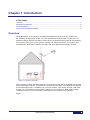
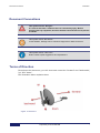
CPE Installation and Pointing User Guide July 2013 Revision Number 1.1 Document Number: DC-002966(D) Notice This document contains information proprietary to Gilat Satellite Networks Ltd. and its affiliates and may not be reproduced in whole or in part without the express written consent of Gilat Satellite Networks Ltd. The disclosure by Gilat Satellite Networks Ltd. of information contained herein does not constitute any license or authorization to use or disclose the information, ideas or concepts presented. The contents of this document are subject to change without prior notice. Contents Chapter 1: Introduction ................................................................................................................ 5 Overview ........................................................................................................................ 5 Document Conventions .................................................................................................. 6 Terms of Direction .......................................................................................................... 6 How to Use This Manual and Kit..................................................................................... 7 Chapter 2: Safety .......................................................................................................................... 8 Warnings ........................................................................................................................ 8 Cautions ......................................................................................................................... 9 Notices ........................................................................................................................... 9 Chapter 3: Box Contents ............................................................................................................ 11 What's in the Box.......................................................................................................... 11 Packing List .................................................................................................................. 13 Dish Assembly Box .................................................................................................................. 13 Modem Packaging Box ............................................................................................................ 16 Transceiver Packaging Box ..................................................................................................... 16 Hardware Bag .......................................................................................................................... 17 Documentation Bag ................................................................................................................. 18 What's Not in the Box ................................................................................................... 18 Tools ........................................................................................................................................ 18 Pointing Data ........................................................................................................................... 19 Chapter 4: Installing Equipment ................................................................................................ 21 Selecting Dish Location ................................................................................................ 21 Installing Pole ............................................................................................................... 22 Installing Dish ............................................................................................................... 22 Assembling Back Bracket with Az/El ....................................................................................... 23 Mounting Az/El on Pole ............................................................................................................ 24 Setting Nominal Elevation ........................................................................................................ 26 Mounting Reflector ................................................................................................................... 28 Attaching Boom Arm to Back Bracket...................................................................................... 31 Assembling Transceiver Bracket and Transceiver .................................................................. 32 Assembling Transceiver Bracket on Boom Arm ...................................................................... 33 Threading RF Cables Through the Boom ................................................................................ 34 Connecting Cables to Transceiver ........................................................................................... 35 Grounding Transceiver ............................................................................................................ 35 Setting Nominal Skew .............................................................................................................. 36 Setting Nominal Azimuth.......................................................................................................... 37 Threading the Cables into House ............................................................................................ 40 Assembling Indoor Connectors ................................................................................................ 40 July, 2013 i Proprietary and Confidential Chapter 5: Modem Configuration............................................................................................... 43 Choosing Installation Time ........................................................................................... 43 Installing and Connecting Modem ................................................................................. 43 Connecting RF Cables to Modem ............................................................................................44 Connecting Modem to Power Adapter .....................................................................................45 Connecting Modem to PC ........................................................................................................45 Supported Operating Systems and Browsers ..........................................................................45 Configuring Computer ..............................................................................................................46 Entering Installation Parameters ..............................................................................................52 Dish Pointing Preparation ........................................................................................................53 Dish Pointing ............................................................................................................................54 Modem Installation ...................................................................................................................60 Dish Repointing ........................................................................................................................64 Appendix A: Dish Pointing Smartphone Applications ............................................................. 65 Appendix B: System Monitoring ................................................................................................ 67 Status ........................................................................................................................... 67 Information ................................................................................................................... 67 Diagnostics ................................................................................................................... 67 Installation Log .........................................................................................................................67 CPE Self-Test ..........................................................................................................................68 Technician .................................................................................................................... 70 Appendix C: List of Acronyms ................................................................................................... 71 Appendix D: Error Messages ..................................................................................................... 73 Appendix E: Troubleshooting .................................................................................................... 75 Elevation/Azimuth Screw Is not Moving ........................................................................ 75 Modem LEDs Are not On .............................................................................................. 75 I Cannot Connect to Modem ......................................................................................... 76 During Installation, Web Page Freezes ......................................................................... 76 Transceiver Emits No Sounds ...................................................................................... 76 I Cannot Lock Onto Satellite ......................................................................................... 76 I Am Experiencing a Deterioration of Service ................................................................ 77 I Cannot Obtain Peak Tone .......................................................................................... 77 Appendix F: (Optional) TV Reception Kit .................................................................................. 78 Kit Contents .................................................................................................................. 78 Assembling TV Kit ........................................................................................................ 80 Appendix G: FAQs ...................................................................................................................... 83 What download/upload speeds can I achieve? ............................................................. 83 Is there any dangerous radiation? ................................................................................ 83 Can I buy another modem and put splitters on the cables? .......................................... 83 Overview Can I add a wireless router or an Ethernet switch behind the modem?......................... 83 Can weather conditions affect modem reception? ........................................................ 83 Are any Internet ports/addresses blocked? ................................................................... 84 Can I watch movies online? .......................................................................................... 84 Do I need authorization to install satellite dish? ............................................................ 84 What do I do if I cannot find installation CD/equipment, etc.? ....................................... 84 What do I do if some of the equipment is damaged? .................................................... 84 What are the best conditions for dish installation? ........................................................ 84 Index 85 July, 2013 iii Proprietary and Confidential Chapter 1: Introduction In This Chapter Overview .......................................................................................................................................... 5 Document Conventions .................................................................................................................... 6 Terms of Direction ............................................................................................................................ 6 How to Use This Manual and Kit ...................................................................................................... 7 Overview Congratulations on purchasing a Gilat’s broadband Internet-over-Ka satellite kit. By following a few simple steps, you will assemble a satellite dish and point it to a satellite orbiting 36,000 km above earth. Once the dish has been pointed successfully, the modem will log on to the system. During the logon procedure, the system will automatically determine whether the dish has been pointed accurately enough. Figure 1: System Overview Once pointing quality has been approved, Internet access will be available as per the service package ordered. The Internet connectivity provided over satellite is identical to terrestrial Internet: it enables you to surf the Web, view online movies, chat with friends, etc. The Internet connection enables you to connect to Web sites or other computers that are not necessarily connected to the Internet over satellite. Enjoy! July, 2013 5 Proprietary and Confidential Document Conventions Introduction Document Conventions This symbol means "Danger!" It is used to describe a situation that can cause bodily injury. Before working with any equipment, know the hazards involved and how to prevent accidents. This symbol means "Be careful!" In this situation, damage can be caused to equipment or data can be lost. This symbol means "Take note!" Notes contain helpful suggestions and explanations. Terms of Direction Throughout this document, you will encounter terms like "forward" and "backwards", "up" and "down". The illustration below explains them. Figure 2: Directions CPE Installation and Pointing 6 Proprietary and Confidential How to Use This Manual and Kit How to Use This Manual and Kit We recommend using the kit in the following order: Read the manual Watch the installation video CD Start the installation July, 2013 7 Proprietary and Confidential Warnings Safety Chapter 2: Safety Warnings Please read all operating instructions and safety precautions in this manual prior to any installation works. Install the modem, dish, and wiring according to national and local regulations issued by authorities. Mount the dish on a properly anchored pole or bracket, capable of bearing the dish weight and wind load. Use the anchoring material and method suitable to the structure and mechanical properties of surface. Different types of walls and roofs may need different types of anchors for mounting dish pole. Consult with a licensed constructor if in any doubt. When working where there is a risk of falling from heights follow and maintain safety regulations for work at height: Use a proper elevating work platform, scaffold, or ladder of proper design and weight rate. Install and use fall-arrest system. Wear protective clothing such as footwear that minimizes the risk of slipping, wear safety helmet well secured to head so that it remains in place should the person fall. Postpone installation to avoid work in bad weather conditions, when rain may make surfaces slippery, when windblasts might impose unexpected forces on dish, when there is a risk of thunderstorm, or when it is too dark. During installation, tightly secure all parts to avoid potential danger to persons and surroundings. Restrict access to area near or below working place. For safety reasons, work and install the dish at a safe distance from power lines. To conform to the law, the installer must follow IEC 60728-11 – Cable networks for television signals, sound signals, and interactive services – Part 11: Safety. Consult with a licensed electrician if in doubt. With reference to standard IEC 60728-11, according to risk assessment per site conditions - select proper method and install proper means of protection, such as air terminal, down-conductor, grounding system, equipotential bonding conductors, Surge Protection Devices on alternating current power and on Ethernet lines. Before installing the modem, make sure that your electrical outlet is properly wired and your computer equipment is properly grounded. RF Radiation Hazard: The transmitting equipment on dish is capable of generating RF electromagnetic field. Keep the space between feed horn and reflector (the radiation beam) clear: do not enter the radiation beam of the dish reflector when the modem is powered and connected to the transmitter. Note that during the pointing procedure the transmitter is powered down, therefore there is no reason for concern during installation. CPE Installation and Pointing 8 Proprietary and Confidential Cautions Different types of power cords may be used for connections to the electrical outlet. Use only a main line cord that complies with safety requirements of the country of use. Do not use power cord if damaged. Connect the power cord to a properly grounded three-prong alternating current outlet only. Do not use adapter plugs. Do not remove the grounding prong from the plug. To prevent electrical shock, fully insert the power plug into power outlet with no part of the prongs exposed. To prevent fire or shock hazard, do not expose the modem to rain or moisture. Do not expose to dripping or splashing and do not place liquid filled objects on the modem. Cautions To prevent overheating, do not block the ventilation holes on the top surface of the modem. Do not stack the modem on top of or below other electronic devices. Do not place the modem in location subjected to direct sun light. Do not place the modem near heat sources. When the modem is placed in an enclosure or cabinet - provide proper ventilation. Only use the power supply provided with the modem. Using a different power supply might damage the equipment. Do not connect or disconnect coaxial cables when the modem is powered. DC voltages are present on the coaxial connectors. To avoid damage by static electricity, disconnect or re-connect the Ethernet cable from the modem or from computer only when the modem is connected to power adapter and to alternating current outlet. When connected to wall alternating current outlet via power supply, the modem is well discharged from static electricity. To minimize faults of cables disconnection, mount the modem in permanent location and final position, not expected to be moved or re-positioned in the future. Coaxial cables might disconnect from connectors if subjected to mechanical movements. To avoid equipment damage, only wipe the unit with a clean, dry cloth, never use fluids, chemicals, or spray cleaners directly. The system has no user-serviceable parts. Do not attempt to open and service the product by yourself: this will void the product's warranty. Do not perform any actions other than those contained in the installation and troubleshooting instructions. Refer all servicing to qualified service professionals. Notices To ensure regulatory and safety compliance, use and properly install the provided power and coaxial cables – or equivalent only - which conform to the specifications within this manual. In some countries, authorization is needed for installing satellite dish. Consult with your local authorities if in any doubt. July, 2013 9 Proprietary and Confidential Chapter 3: Box Contents In This Section What's in the Box ........................................................................................................................... 11 Packing List .................................................................................................................................... 13 What's Not in the Box ..................................................................................................................... 18 What's in the Box It is important to open the box in a suitable location to ensure the modem is not exposed to excessive humidity and/or extreme temperatures. To inspect the contents of the box: 1. Open the box. Figure 3: Opening the Box 2. Compare the contents of the box with the packing list. July, 2013 11 Proprietary and Confidential What's in the Box Box Contents Figure 4: Box Contents The box must contain the following kit components: # Description 1 Az/El with clamps 2 Back bracket 3 Skew plate 4 Reflector 5 Boom arm 6 Transceiver bracket 7 Transceiver 8 RF cables and F-connectors 9 Grounding cable bag 10 Modem box 11 TV Receiver Bracket/Holder Kit (optional) 12 Hardware Bag 13 Documentation Bag 3. Compare the contents of the box with the Packing List (on page 13). CPE Installation and Pointing 12 Proprietary and Confidential Packing List If something is missing/damaged/wrong, contact your supplier. 4. Set aside the modem box for later use. Figure 5: Modem Box 5. Put the rest of the components back into the kit box to make it easy to transport to the dish installation location. Packing List Dish Assembly Box # Item Quantity 1 RF Cable (SIAM) 1 30M Image July, 2013 13 Proprietary and Confidential Packing List Box Contents # Item Quantity 2 Reflector 1 3 Boom arm 1 4 Transceiver bracket 1 5 Back bracket 1 Image CPE Installation and Pointing 14 Proprietary and Confidential Packing List # Item Quantity 6 Az/El (assembled with pole clamps) 1 7 Skew plate 1 8 Hardware bag 1 set - see below 9 Documentation bag 1 set - see below 10 Modem packaging box 1 set - see below 11 Transceiver packaging box 1 set - see below Image July, 2013 15 Proprietary and Confidential Packing List Box Contents Modem Packaging Box The box includes the following items: # Item Quantity 1 SkyEdge II-c Aries modem 1 2 Power adapter 1 3 Power cable 1 4 LAN Cable 1 5 F-connector 2 Figure 6: Modem Box Transceiver Packaging Box The box includes the following items: # Item Quantity 1 Transceiver with Feed and Polarizer 1 2 Grounding screw 1 3 Allen key 1 CPE Installation and Pointing 16 Proprietary and Confidential Packing List Figure 7: Transceiver Box Content Hardware Bag The bag includes the following items: Dish Assembly Kit # Item Description Quantity 1 Bolt M8X20 Carriage bolt - short neck, M8x1.25mm thread 9 2 Spring Washer for 8-mm bolt 9 3 Flat Washer for 8-mm bolt 9 4 Nut Hex M8X1.25 9 Mounting Kit # Item Description Quantity 1 Arrow Elevation offset arrow 1 Transceiver / Boom Arm Assembly Kit # Item Description Quantity 1 Screw Hex socket head cap screw 4 2 Washer Spring washer M4 4 3 Screw Hex head screw M8 8 4 Washer Flat washer M8 8 5 Washer Spring washer M8 8 July, 2013 17 Proprietary and Confidential What's Not in the Box Box Contents Grounding Kit # Item Description Quantity 1 Screw Hex head tapping screw, 1/4-20 x 5/8 1 2 Washer Ext tooth lock washer 1/4" 1 3 Wire Grounding wire 1 Documentation Bag The box includes the following items: # Item Quantity 1 CD 1 2 Quick Guide 1 What's Not in the Box What you need to provide: A Leveled Pole Tools for the installation Pointing Data If you are planning to use the dish for satellite TV reception, you will also need a TV bracket. Tools Tools required for the installation of the satellite dish: A spanner (wrench): open and closed hexagonal metric 13 mm (preferably ratchet type) A flat-blade screwdriver (Optional) A Phillips type screwdriver A compass A cable cutter A ruler (10-30 cm) Cable wraps / ties CPE Installation and Pointing 18 Proprietary and Confidential What's Not in the Box Pointing Data The invoice contains important data necessary for successful installation. Do not start the installation unless you have the invoice with all the data (see below). Pointing data (appears in the invoice): Satellite name Elevation value Azimuth value Skew value Location code RF Cluster code July, 2013 19 Proprietary and Confidential Chapter 4: Installing Equipment In This Section Selecting Dish Location.................................................................................................................. 21 Installing Pole ................................................................................................................................. 22 Installing Dish ................................................................................................................................. 22 Selecting Dish Location Determine the suitable location for your satellite dish. Selecting a suitable outdoor location with a clear view towards the satellite is very important: obstructions (e.g., buildings or trees) may affect the signal strength. The cable is 30 m long. The distance between the satellite dish and the modem location should not exceed this distance. Figure 8: Unsuitable Location 1 July, 2013 21 Proprietary and Confidential Installing Pole Installing Equipment Figure 9: Unsuitable Location 2 For information on how to select dish location using a smartphone application, refer to Dish Pointing Smartphone Applications (on page 65). Installing Pole When installing the pole for the dish, follow these guidelines: The pole diameter must be between 45 and 70 mm. The pole must be installed on a solid base. Mechanical forces to be considered: 2 The wind load of the dish is 495 N at pressure of 800 N/m according to EN 60728-11. The maximum bending moment of the mounting mast (1000mm high) at the fixing point is 495 NM. The rotational stiffness of the dish mount shall be better than 0.02° at operational wind speed of 70 km/h. Installing Dish Bring the kit box with its contents to the place where you have installed the pole, and spread out the components of the dish and transceiver for assembly and outdoor installation. Tip: Leave the box containing the modem indoors. The box is shown in the Figure below. CPE Installation and Pointing 22 Proprietary and Confidential Installing Dish Figure 10: Modem Box Assembling Back Bracket with Az/El To assemble the back bracket on the Az/El: 1. Place the Az/El, clamps down, on an even surface so that its elevation bracket surface faces upwards. July, 2013 23 Proprietary and Confidential Installing Dish Installing Equipment Figure 11: Assembling the Back Bracket with the Az/El 2. Position the back bracket with its rear surface to the Az/El. 3. Apply the skew plate to the back bracket with the arrow marking facing forward. 4. Insert the four bolts through the holes in the skew plate and the Az/El. 5. From the rear side, place a flat washer, a spring washer, and thread a nut on each bolt. 6. Tighten the nuts by hand leaving enough freedom to allow rotation of the back bracket. Mounting Az/El on Pole To mount the Az/El+back bracket on the pole: 1. Loosen the clamp nuts. 2. Release the clamps from the bolts on the open side. CPE Installation and Pointing 24 Proprietary and Confidential Installing Dish Figure 12: Clamps Released 3. Place the Az/El on the pole. 4. Reposition the clamps on the bolts. To ensure a sturdy mount, make sure that the clamp has been shifted in the direction of its open end as far as possible. 5. Tighten the nuts by hand. July, 2013 25 Proprietary and Confidential Installing Dish Installing Equipment Figure 13: Tightening the Nuts Tips: It is important to partially tighten the nuts to prevent the assembly from sliding down the pole under its own weight, but leave some leeway to allow the rotation of the assembly around the pole with just a moderate effort during the pointing procedure. It is desirable to tighten each nut 1/2 turn at a time, moving from nut to nut in a crisscross manner (1-2-3-4) as shown in the Figure above, slowly increasing the tension. Setting Nominal Elevation To set the nominal elevation: 1. Verify that the two nuts retaining the Az/El vertically movable part (marked with a larger circle) are loose. Keep in mind there are two nuts, one at each side! CPE Installation and Pointing 26 Proprietary and Confidential Installing Dish Figure 14: Retention Nuts 2. Verify that the two nuts retaining the Az/El horizontally movable part (marked with smaller circles) are loose. 3. Rotate the elevation screw to set the nominal elevation value as indicated in the invoice. Figure 15: Elevation Screw July, 2013 27 Proprietary and Confidential Installing Dish Installing Equipment The Az/El unit is supplied preset to 20 degrees elevation (see Figure above). The bars of the elevation scale have a 2-degree resolution; smaller markings in between provide a 1-degree grid. Mounting Reflector To mount the reflector: 1. Verify that the back bracket rotates freely relative to the skew plate. If the rotation is not free enough, you need to slightly release the nuts of the four bolts holding the skew plate. 2. Rotate the back bracket around the skew plate until the U-slot faces upward. Figure 16: Back Bracket - U-slot 3. Insert a bolt into the uppermost hole of the reflector from the concave side. CPE Installation and Pointing 28 Proprietary and Confidential Installing Dish Figure 17: Reflector - Uppermost Hole 4. Put a flat washer and a spring washer on the bolt. 5. Thread a nut 2-3 threads onto the bolt. Figure 18: Dish above U-Slot 6. Bring the reflector in contact with the back bracket and slide it down so that the bolt would enter the U-slot of the back bracket to establish the initial positioning. July, 2013 29 Proprietary and Confidential Installing Dish Installing Equipment Figure 19: Nut Threaded Halfway on Bolt 7. Insert the remaining four bolts to attach the reflector to the back bracket. Figure 20: Reflector with Screws Inserted 8. On each bolt, place a flat washer, then a spring washer, then a nut. CPE Installation and Pointing 30 Proprietary and Confidential Installing Dish Figure 21: Reflector Attached to Back Bracket 9. Tighten all the nuts by hand first; complete the tightening of all the nuts with a spanner/ratchet. Attaching Boom Arm to Back Bracket To attach the boom arm to the back bracket: 1. Insert the reflector end of the boom arm into the back bracket all the way, until it locks into position. Figure 22: Inserting Boom Arm into Back Bracket 2. Insert and tighten the four bolts (with flat and spring washers) - two at each side. July, 2013 31 Proprietary and Confidential Installing Dish Installing Equipment Figure 23: Attaching Boom Arm Assembling Transceiver Bracket and Transceiver To assemble the transceiver bracket and the transceiver: 1. Apply the bracket onto the transceiver as shown in the Figure below. Figure 24: Assembling Transceiver on Bracket 2. Verify that the transceiver top and bottom sides are facing up and down, respectively (Rx connector is above, Tx connector is below). CPE Installation and Pointing 32 Proprietary and Confidential Installing Dish 3. Insert the four bolts with spring washers to secure the transceiver on the transceiver arm. 4. Tighten the four bolts with the Allen key (supplied). Assembling Transceiver Bracket on Boom Arm To assemble the transceiver bracket on the boom arm: 1. Put the transceiver bracket on the feed end of the boom arm. Figure 25: Assembling Transceiver Bracket on Boom Arm 2. Insert and tighten the four bolts with flat and spring washers - (two at each side). July, 2013 33 Proprietary and Confidential Installing Dish Installing Equipment Figure 26: Attaching Bracket to Arm If you have purchased the optional TV Reception kit, please refer to (Optional) TV Reception Kit (on page 78). Threading RF Cables Through the Boom Each coaxial cable is equipped with a connector on the outdoor end. The indoor end of the cable has no connectors attached. To thread the RF cables through the boom: 1. Feed the outdoor ends of the cables (with the pre-attached F-connectors) through the boom in the direction of the transceiver. If threading through the boom is problematic or impossible due to complicated installation conditions, just attach the cables to the boom (preferably under the boom) with 2-3 cable ties/straps. 2. Leave 1m of extra cable between the boom arm and the transceiver. CPE Installation and Pointing 34 Proprietary and Confidential Installing Dish Connecting Cables to Transceiver To connect the cables to the transceiver: 1. Screw the male F-connectors of the RF cables onto the corresponding female RF-connectors of the transceiver (Rx to Rx, and Tx to Tx) leaving a loop of cable (excess length) as shown in the Figure below. Figure 27: Connecting Cables to Transceiver Grounding Transceiver To ground the transceiver: 1. Connect one end of the equipotential bonding cable to the transceiver using the screw provided, as shown in the Figure in the previous section. July, 2013 35 Proprietary and Confidential Installing Dish Installing Equipment 2. Connect the other end of the equipotential bonding cable to the pole clamp using the screw provided. Figure 28: Grounding BUC to Pole Clamp 3. Ground the pole supporting the dish assembly according to local regulations. Grounding can be done by attaching a down-conductor to the grounding screw of the back bracket (as shown in the image above) with a 6.5mm ring-terminal (not provided with this kit). Setting Nominal Skew To set the skew value: 1. Rotate the back bracket-reflector assembly around the Az/EL-skew plate assembly to set the skew value as indicated in the invoice. CPE Installation and Pointing 36 Proprietary and Confidential Installing Dish Figure 29: Skew Scale 2. Tighten the four nuts holding the Az/EL-skew plate assembly together. Setting Nominal Azimuth At this stage, the bolts of the clamps should be partially tightened so that the Az/El is flush against the pole yet loose enough to allow it to rotate smoothly around the pole. To set the nominal azimuth: 1. Verify that the fine-tuning grid (see the Figure below) is set to zero. If not, adjust using the azimuth screw. July, 2013 37 Proprietary and Confidential Installing Dish Installing Equipment Figure 30: Azimuth Fine-Tuning Grid 2. Using a compass, determine the direction to point the dish according to the azimuth value provided in the invoice. 3. Rotate the dish assembly around the pole so as to point its front surface in the direction determined. 4. Attach the elevation offset arrow. CPE Installation and Pointing 38 Proprietary and Confidential Installing Dish Figure 31: Elevation Offset Arrow If the pole is not ideally vertical, you will notice the offset on the offset scale (see the Figure below). Keep in mind that the bars of the elevation scale have a 2-degree resolution; smaller markings in between provide a 1-degree grid. The offset scale has 1-degree markings. 5. Check the elevation offset value. July, 2013 39 Proprietary and Confidential Installing Dish Installing Equipment Figure 32: Elevation Offset Scale 6. If a non-zero offset value is determined, adjust the position of the dish accordingly: for positive offset, increase the elevation (e.g., the invoice indicates 33 degrees elevation, and the elevation offset scale shows +1 degree; to compensate for the pole deviation, set the elevation to 34 degrees). for negative offset, decrease the elevation. Threading the Cables into House You may need to drill holes in order to thread the cables into the house. As wall materials vary, you may need to contact your local specialist for advice on particulars. Make sure to drill these holes at an angle that prevents the water from seeping into the house: when drilling from the outside, the drill must be pointed slightly upwards. Assembling Indoor Connectors To make threading the cables through narrow openings an easier task, the indoor ends of the cables have no connectors attached. This also allows you to adjust the length of the cable removing the extra length. You will need a cutter (and probably pliers as well) to connect the F-connectors. To attach the F-connectors to the indoor ends of the cables: 1. (Optional) Roll the excess cable into a coil, or shorten the cables to the desired length if they are too long for your room layout. CPE Installation and Pointing 40 Proprietary and Confidential Installing Dish Shortening the cables must be performed carefully: they are supplied with Tx and Rx stickers; cutting off the excess length of both cables together will make it impossible to determine which cable is which. You need to cut one cable first, and mark it (Rx or Tx, depending on which cable you are cutting off) with a permanent marker or a sticker to ensure that after cutting off the other cable, you will be able to determine which cable is which. Note that one of the cables has a running mark printed lengthwise - it also allows you to differ between the Rx and Tx cables. 2. Strip about 18 mm of the outer jacket only. 3. Fold the wire shielding backwards over the cable jacket (but do not remove the aluminium foil). 4. Strip 8 mm to the inner conductor. 5. Insert the stripped end of the cable into the F-connector as deep as you can. 6. Screw the F-connector on the wire by hand, applying sufficient force, until the internal insulation is aligned with the rim of the connector. Verify that throughout, the procedure the cable is centered and straightened in the connector. Otherwise, you will not be able to screw the connector to the end-position on the cable. July, 2013 41 Proprietary and Confidential Installing Dish Installing Equipment Figure 33: Connector Assembled on Cable 7. Repeat this procedure assembling the other cable and F-connector. CPE Installation and Pointing 42 Proprietary and Confidential Chapter 5: Modem Configuration In This Section Choosing Installation Time ............................................................................................................. 43 Installing and Connecting Modem .................................................................................................. 43 Choosing Installation Time Service is available 24/7; therefore, installation can be performed anytime. For safety reasons, it is advisable to install the dish during the day. Initial pointing must be performed under clear sky condition to guarantee accurate pointing: pointing in rainy, cloudy, or windy weather can interfere with the stability of indicators. Installing and Connecting Modem To start modem installation: Unpack the modem as shown in the Figure below. July, 2013 43 Proprietary and Confidential Installing and Connecting Modem Modem Configuration Figure 34: Unpacking Connecting RF Cables to Modem To connect the RF cables to the modem: 1. Screw the male cable F-connector marked Rx on the RF IN female connector on the modem (see arrow 1 in the Figure below). Figure 35: RF Connections 2. Screw the male cable F-connector marked Tx on the RF OUT female connector on the modem (see arrow 2 in the Figure above). CPE Installation and Pointing 44 Proprietary and Confidential Installing and Connecting Modem Connecting Modem to Power Adapter To power up the modem: 1. Connect the power adapter provided in the kit to the modem. 2. Connect the power adapter to a wall outlet. The Power LED goes On. The modem performs a quick Power-On Self-Test (POST): the LEDs blink in a rapid succession. On POST completion, the Power LED remains On, the rest of the LEDs remain Off. Connecting Modem to PC To connect the modem to a PC: 1. Connect one end of the LAN cable provided with the kit to the Ethernet port of the modem. 2. Connect the other end of the LAN cable to the Ethernet port of the PC. If the distance between the devices exceeds the length of the standard cable, you will need to obtain a longer cable. 3. Verify that the green LEDs of the LAN sockets of the modem and the PC are On. During the installation, the modem must be connected to the PC directly with a single cable. Attempting to install the modem with a router connected will interfere with the installation process. Once the installation has been completed and service is up, you may connect a router. Supported Operating Systems and Browsers Supported operating systems and browsers: Windows XP and above (32- and 64-bit): IE 7 and above FireFox 10 and above Chrome 18 and above iPAD iOS 5.1 Safari July, 2013 45 Proprietary and Confidential Installing and Connecting Modem Modem Configuration Other OSs and browsers may work equally well, but have not been tested. You may use them at your own discretion. Configuring Computer Before configuring the modem, you need to verify that your computer is configured properly: 1. DHCP settings must be enabled. 2. Proxy server must be disabled. See the next section for details. Windows 7 Enabling DHCP To enable DHCP on the LAN adapter: 1. Click Start Control panel. Figure 36: Win7 DHCP 2. In the Network and Internet section, click View Network Status and Tasks. Network and Sharing Center page is displayed. CPE Installation and Pointing 46 Proprietary and Confidential Installing and Connecting Modem Figure 37: Win7 DHCP 1 3. In the left panel of the Network and Sharing Center page, click Change adapter settings. Available LAN adapters are displayed. Figure 38: Win7 DHCP 2 4. Right-click the desired LAN adapter and select Properties. LAN Adapter properties box is displayed. July, 2013 47 Proprietary and Confidential Installing and Connecting Modem Modem Configuration Figure 39: Win7 DHCP 3 5. Double-click Internet Protocol Version 4 (TCP/IPv4). TCP/IPv4 box is displayed. CPE Installation and Pointing 48 Proprietary and Confidential Installing and Connecting Modem Figure 40: Win7 DHCP 4 6. Verify that Obtain an IP address automatically and Obtain DNS server address automatically are selected (if not, select), and click OK. Disabling Proxy Server Connection To disable a proxy server connection option: 1. In Internet Explorer, click Tools Connections tab. Internet Options and select the July, 2013 49 Proprietary and Confidential Installing and Connecting Modem Modem Configuration Figure 41: Disabling Proxy 1 2. Click LAN settings and verify that the Use a proxy server for your LAN checkbox is not selected. CPE Installation and Pointing 50 Proprietary and Confidential Installing and Connecting Modem Figure 42: Disabling Proxy 2 3. Click OK to save the configuration. The dialog box is no longer displayed. 4. In the Internet Options box, click OK to close the Internet Options dialog box. MacOS Enabling DHCP To enable DHCP on the LAN adapter: 1. From the Apple menu, select System Preferences. 2. Click the Network icon. 3. From the Location drop-down menu, select Automatic. 4. Select Ethernet (or the network adapter you wish to change the settings for). 5. Select Using DHCP from the Configure IPv4 pull down menu 6. Click Apply. Disabling Proxy Server Connection To disable proxy server connection: 1. Launch Safari. 2. Click on the Safari menu. 3. Select Preferences from the drop-down menu. 4. Select the Advanced tab. 5. Click on the Change Settings button. The Network window is displayed. 6. Click on the Configure Proxies drop-down menu and select Manually. 7. Uncheck all proxy settings within the Select a protocol to configure menu. July, 2013 51 Proprietary and Confidential Installing and Connecting Modem Modem Configuration 8. Click OK to confirm. 9. Click Apply. Entering Installation Parameters Do not start the installation until you verify that you have the Location Code and the RF Cluster Code (see the invoice). Without these parameters, you cannot successfully complete the modem configuration procedure. All captures in this section were taken using Microsoft Internet Explorer. The screens viewed when using other Web browsers may be slightly different in appearance. All captures in this section were carried out on a CPE running basic software. Once the CPE connects to the system, it downloads additional software. The actual screens may be slightly different in appearance. To start the modem configuration: 1. On your PC, start your Internet browser to access the Installation Page. The Installation Page is stored on the modem itself - you do not need an Internet connection to access this page. 2. Type http://sky.manage in the address field, and press Enter. The start page is displayed. Figure 43: Modem Configuration Starting Page 3. Select the desired language. CPE Installation and Pointing 52 Proprietary and Confidential Installing and Connecting Modem Language can be changed at any step. 4. Enter the location and the RF cluster codes, and click Next. The Dish Pointing page is displayed. Continue to the next section - Dish Pointing Preparation (on page 53). Dish Pointing Preparation To prepare the modem for dish pointing: 1. In the Modem Configuration Starting Page screen, review the required steps. Figure 44: Dish Pointing Preparation Page 1 2. Click Start Pointing. The Dish Pointing Preparation Page 2 is displayed. (Or click Back to make changes in the installation parameters.) July, 2013 53 Proprietary and Confidential Installing and Connecting Modem Modem Configuration Figure 45: Dish Pointing Preparation Page 2 3. The modem is ready to respond to the signal power fluctuations that will occur while you are pointing the dish. If nominal azimuth happens to be set accurately, the above screen may look slightly differently - showing that the signal is locked. At this point, the transceiver starts emitting the Searching tone indicating that it is seeking the carrier. Regarding the beeping tones: view the accompanying video to get a good idea of the different tones. 4. You can now leave the PC, move to the place where the dish is located, and start pointing it. Continue to the Dish Pointing (on page 54) section. Dish Pointing Audio Indication The transceiver has a built-in speaker that allows the system to indicate the state and power of the signal. The sounds emitted by the transceiver can be divided into the following types: Searching – indicates that the CPE is in installation stage but the modem is not locked yet. Transition2Lock – a short two-second transitional tone indicating that the modem is locked. Following this tone, the transceiver will immediately start to emit one of the locked tones, according to the reception level. Locked – a range of beeps indicating that the modem is locked on the satellite. Pitch and stagger rate are proportionate to the level of reception: the better the reception the higher the pitch and the faster the stagger rate. CPE Installation and Pointing 54 Proprietary and Confidential Installing and Connecting Modem LockLowSNR LockMedSNR LockMaxSNR Peak – At any given time during the pointing there is a maximum reception level registered. This level will gradually increase as the pointing progresses. The peak continuous tone is coupled to the maximum reception level. Transition2Searching - if the Locked state is lost during the pointing, there will be a 2-second transitional tone (as a police car siren), which will be followed be the Searching tone. Abort – A mismatch between the parameters entered and the kit installed. Figure 46: Sound Visualization Coarse Pointing To perform the coarse pointing: 1. Verify that the nominal elevation, azimuth and skew values are set correctly. Before you proceed to the next step: Do not apply force to the reflector. Excessive pressure on the reflector can cause reflector deformation. Hold the dish assembly at the back structure and Az/El while rotating it. 2. Rotate the dish as slowly as possible (approximately 1 degree per second) around the pole in one direction until the beeping tone changes, indicating that the modem is locked on the satellite. The Locked state is indicated by a 2-second transitional tone (Transition2Lock). July, 2013 55 Proprietary and Confidential Installing and Connecting Modem Modem Configuration The Abort tone will be heard if the kit installed is not compatible with the RF cluster code entered. Stop the installation and contact the Help Desk. Typically the initial nominal elevation setting should be sufficient for locking - but not the azimuth setting. In the unlikely event that initial azimuth setting was accurate, one of the Locked tones (LockLowSNR, LockMedSNR, LockMaxSNR) will be heard from the very start, instead of the Searching tone. Proceed to Step 4 below. If the Locked tone is not obtained after rotating the dish 30 degrees from the nominal azimuth value, rotate it in the opposite direction, passing the nominal azimuth value by no more than 30 degrees in the opposite direction. If the Locked tone is still not obtained, repeat the rotation three more times, each time at a slower pace than the previous one. If the Locked tone is not obtained after that, double-check all settings and verify that there is a clear line of sight to the satellite. 3. Once the transceiver emits the Locked tone, stop rotating the dish at once. After the Transition2Lock tone is heard, there will be a beeping tone indicating that the carrier is locked. The pitch and stagger rate of this tone are proportionate to the level of reception: At low reception levels, there will be a low pitch and low stagger rate tone (LockLowSNR). At medium reception levels, there will be a medium pitch and medium stagger rate (LockMedSNR). At maximum reception levels, there will be a Max pitch and Max stagger rate tone (LockMaxSNR). Throughout the entire procedure, the tones will change accordingly. 4. Record the position of the elevation offset arrow. 5. Firmly tighten the clamp nuts that hold the dish assembly on the pole, to prevent further change of its position relative to the satellite. Tightening should be done half a turn at a time. CPE Installation and Pointing 56 Proprietary and Confidential Installing and Connecting Modem Figure 47: Tightening the Nuts Tightening the nuts, the way it is described above is not mandatory, but it is recommended. Tightening the nuts in a different way may cause a change in the assembly position to the extent that the actual elevation and azimuth values will considerably differ from the nominal values. Excessive tightening will damage the bolts, nuts, or clamps. Take care not to warp the clamps. 6. If the elevation offset arrow position changes after tightening the bolts, adjust the elevation accordingly. July, 2013 57 Proprietary and Confidential Installing and Connecting Modem Modem Configuration Once you tighten the nuts, the settings may change; consequently, the audio tones might change. This is the expected normal mode of operation. Fine Pointing The process is completed by fine-tuning the dish position using the built-in tuning tool until the strongest signal is obtained. Fine pointing of the dish can be started once a Locked tone (LockLowSNR, LockMedSNR, LockMaxSNR) is being constantly emitted by the transceiver. If the Locked tone is lost during the clamp tightening, you need to reacquire the signal by modifying the elevation setting by +/- 2 degrees around the nominal value. If the Locked tone is not achieved, return to the nominal value and modify the azimuth setting by +/- 2 degrees around the zero setting. If neither of these measures helps to obtain the Locked tone, you need to repeat the coarse pointing procedure. To complete the dish pointing: 1. Using a spanner/ratchet, rotate the azimuth screw to change the azimuth settings on the dish in any direction. Figure 48: Az/El Azimuth Screw 2. Once you can hear the audio signals reduce tone and staggering rate, reverse the direction at once. If, instead of stopping and reversing the direction, you continue too far, you may lose the Locked state. In this case, you will hear a transition tone (Transition2Searching). 3. At some point, you will hear the pitch increase, and the tone will change from staggering to continuous (Peak). Continue in the same direction until staggering tone starts again. Reverse the direction once again and stop as soon as you hear a continuous tone. CPE Installation and Pointing 58 Proprietary and Confidential Installing and Connecting Modem If the continuous tone position is not achieved, stop at the highest-pitch staggering tone (which indicates the strongest signal available) 4. Using a spanner/ratchet, rotate the elevation screw to change the elevation settings in either direction until the audio tone drops in pitch and stagger rate. Reverse the direction until a continuous tone position is achieved. Continue in the same direction until staggering tone starts again. Reverse the direction again and stop as soon as a continuous tone is achieved. Figure 49: Elevation Fine-Tuning 5. At this point, it is necessary to optimize the azimuth setting for the second time. Using a spanner/ratchet, rotate the azimuth screw to change the azimuth settings in either direction until the audio tone indication drops in tone and stagger rate. Reverse the direction until a continuous tone position is achieved. Continue in the same direction until staggering tone starts again. Reverse the direction again and stop as soon as a continuous tone is achieved. 6. Tighten the nuts: two nuts retaining the Az/El vertically movable part (one at each side - right and left) two nuts retaining the Az/El horizontally movable part July, 2013 59 Proprietary and Confidential Installing and Connecting Modem Modem Configuration Figure 50: Nuts to Be Tightened 7. Apply light pressure on the side and top of the assembly until the tone changes to a staggering tone. Verify that once you let go, the tone returns to peak tone. 8. Once you have completed fine pointing the dish, return to your PC. Continue to Modem Installation (on page 60). Modem Installation To complete the modem installation: 1. In the Dish Pointing Preparation Page 2 screen, click Finish Pointing. CPE Installation and Pointing 60 Proprietary and Confidential Installing and Connecting Modem Figure 51: Locked on Satellite 2. A reminder is displayed. July, 2013 61 Proprietary and Confidential Installing and Connecting Modem Modem Configuration Figure 52: Reminder 3. Click OK to start modem installation if you have tightened the bolts. 4. A 5-step modem installation process starts. You do not need to do anything: just follow the steps to verify that each one of them is completed successfully: a. Step 1/5 - Software Download – The modem is downloading the latest software version. b. Step 2/5 - Forward Channel Acquisition – Modem locks onto the correct carrier for network admission. c. Step 3/5 - Return Channel Acquisition – Modem establishes a return link with the central station. d. Step 4/5 - Network Admission. e. Step 5/5 - Installation Quality Verification – The modem establishes a session with a control device in the central station to verify that the signal quality of the forward channel and return channel is sufficient. At the end of the process, the Installation completed successfully dialog box is displayed: CPE Installation and Pointing 62 Proprietary and Confidential Installing and Connecting Modem Figure 53: Installation Complete box 5. Click Finish to complete the installation. The Home Page containing the system general information is displayed. Figure 54: Modem Installation - Final Screen July, 2013 63 Proprietary and Confidential Installing and Connecting Modem Modem Configuration The current value is often lower than the maximum achieved value. This is the expected behavior as the value constantly fluctuates. There is no need to return to the dish to improve the pointing unless there is an explicit warning (in case the difference between the current value and the maximum achieved value is larger than expected) 6. This step completes the Gilat CPE installation. The user can start browsing the Internet. Dish Repointing If you ever need to repoint the dish, remember to loosen the azimuth and elevation fastening bolts. Trying to rotate the azimuth and elevation screws without first releasing their fastening bolts will damage the Az/El! CPE Installation and Pointing 64 Proprietary and Confidential Appendix A: Dish Pointing Smartphone Applications Satellite finder/dish pointing applications that run on a smartphone allow interposition of the projection of satellite positions on the sky on the actual view via the viewfinder of the built-in camera, based on Augmented Reality. To determine a suitable location using a smartphone: 1. Download a satellite pointer application of your choice. We recommend Satellite AR by Analytical Graphics, Inc. (AGI) - you can download it from http://spacedata.agi.com/MobileApps/about.htm 2. Install the application. 3. Run the application. 4. Visit the desired location where you would like to install the satellite dish. 5. Point the smartphone in the desired direction. 6. Locate the satellite listed in the invoice. 7. Determine whether the location you have selected provides a clear line of sight from the satellite dish to this satellite. If you see any tall objects (trees, buildings etc.) overlapping the satellite projection, the location is not suitable. July, 2013 65 Proprietary and Confidential Appendix B: System Monitoring In This Section Status ............................................................................................................................................. 67 Information ..................................................................................................................................... 67 Diagnostics ..................................................................................................................................... 67 Technician ...................................................................................................................................... 70 Status This page allows you to check the general status of your modem. The message you expect to be displayed is Your modem is working properly! In case of malfunction, you may encounter other messages displayed. Refer to the Error Messages section for solution. Information If you encounter a non-optimal service condition that requires a call to your service provider's technical support center, the technician most probably will ask you to read out what this page says in the following sections: CPE Status CPE Identification Statistics Diagnostics Installation Log The CPE Diagnostics page provides access to the installation log. If your installation process does not result in a "Your modem is working properly!" message in the CPE Status page, and you call your service provider's technical support center, the technician most probably will ask you to read out what this log says. July, 2013 67 Proprietary and Confidential Figure 55: Installation Log CPE Self-Test Self-test is a utility that allows testing modem connectivity, DNS resolution, and upload/download speed after temporarily disconnecting it from the computer (without physically disconnecting the LAN cable). This is done to separate modem-generated errors from issues caused by the computer connected to it. Figure 56: Self-Test CPE Installation and Pointing 68 Proprietary and Confidential Diagnostics To run the modem self-test: 1. Click on Diagnostics 2. (Optional) Select the Speed Test checkbox 3. Click Run Test The results of the self-test are displayed. Figure 57: Self-Test Results 4. To view detailed information, click View advanced information. July, 2013 69 Proprietary and Confidential Figure 58: Test Advanced Information To view the results of the last test, click View Last Test. Technician This page is password-protected and is not user-accessible. CPE Installation and Pointing 70 Proprietary and Confidential Appendix C: List of Acronyms POST Power-On Self-Test CPE Customer Peripheral Equipment DHCP Dynamic Host Configuration Protocol DNS Domain Name Server ISP Internet Service Provider LAN Local Access Network LED Light-Emitting Diode OS Operating System RF Radio Frequency July, 2013 71 Proprietary and Confidential Appendix D: Error Messages The following error messages can be displayed during modem installation. The table below offers possible causes and resolution methods. # Error Message / Error Cause Resolution Description 1 RF Cluster code value is out of range Invalid RF Cluster code entered Enter correct RF Cluster code 2 Location code value is out Invalid Location of range code entered Enter correct Location code 3 On clicking Next in the CPE has detected first page of Install: the Rx cable Rx cable is not connected disconnect properly. Verify: Rx cable connected to RF In port on modem Rx cable indoor end assembled correctly to connector Rx cable connected to Rx port on Transceiver If the problem persists contact operator 4 In Step 2 of installation, the following error dialog is shown: Configuration mismatch detected! CPE has detected that the RF cluster code does not match the kit provided 5 When Finish Pointing Modem is not locked Achieve modem locking button is clicked in Step 2 of installation and dish status is Not Locked: Modem must be locked before ending pointing. 6 Step 3, substep 1/5: software download timeout Modem cannot complete software download Check the Rx/Tx cable connection Restart activation 7 Step 3, substep 3/5: Return Channel Acquisition timeout Modem cannot complete Return Channel Acquisition Restart activation; if the problem persists, contact Help Desk 8 Step 3, substep 4/5: Network Admission timeout Modem cannot complete Network Admission Restart activation; if the problem persists, contact Help Desk 9 In Step 3 of installation, Timeout the following error dialog is shown: Note: [step name] is taking longer than expected. July, 2013 Verify the installation parameters. If the parameters are correct, contact Help Desk. Contact the Help Desk (see contact info in the manual provided with the kit). Once the problem is resolved, click Restart Activation. 73 Proprietary and Confidential # Error Message / Description Error Cause 10 In Step 3 of installation, RF Audit has failed the following error dialog is shown: CPE Installation Failure Pointing may be inaccurate, thus service is prohibited. Resolution Pointing may be inaccurate, thus service is prohibited. Verify that the weather is clear and that there are no obstructions in the line of sight from the dish to the satellite. Click Repoint Dish to improve pointing accuracy. If the problem persists, contact the Help Desk. 11 In the CPE Status, a message is displayed: Modem cannot synchronize with the hub. This could be related to a technical No Sync problem at the Synchronization problem. satellite service provider's site. Wait for a few minutes and restart the modem. If the problem persists, contact the Help Desk. 12 In the CPE Status, a message is displayed: No Satellite Link Link establishment problem. or No Lock If the weather is bad, wait a few minutes. If the weather is good, restart the modem. If the problem persists, contact the Help Desk. Modem cannot establish link to the hub. This could be related to extreme weather conditions either at the user's site or at the satellite service provider's site. CPE Installation and Pointing 74 Proprietary and Confidential Appendix E: Troubleshooting In This Section Elevation/Azimuth Screw Is not Moving ......................................................................................... 75 Modem LEDs Are not On ............................................................................................................... 75 I Cannot Connect to Modem .......................................................................................................... 76 During Installation, Web Page Freezes ......................................................................................... 76 Transceiver Emits No Sounds ....................................................................................................... 76 I Cannot Lock Onto Satellite .......................................................................................................... 76 I Am Experiencing a Deterioration of Service ................................................................................ 77 I Cannot Obtain Peak Tone ........................................................................................................... 77 Elevation/Azimuth Screw Is not Moving Check the fastening nuts to make sure they are loose. Figure 59: Loosening the Screws If the fastening nuts had been tightened, they will prevent the elevation/azimuth screw from further movement. Modem LEDs Are not On This indicates a power supply problem. Check that the electric socket is powered. Check that the electric plug of the power adapter is tightly connected. July, 2013 75 Proprietary and Confidential Check that the power adapter is powered. Check that the modem is connected to the power adapter. If the above measures do not resolve the problem, contact Help Desk. I Cannot Connect to Modem 1. Check the power. 2. Check the LAN configuration on your PC. 3. Check the LAN LEDs of the PC and the modem. 4. Replace the LAN cable. If the above measures do not resolve the problem, contact Help Desk. During Installation, Web Page Freezes In some cases, during the installation/reinstallation, the Web page freezes for a prolonged period. 1. Verify that no additional 3rd party equipment (e.g., a wireless router) is installed between the modem and the PC. 2. Connect the PC directly to the modem with an Ethernet cable. If the Web page does not refresh, restart the modem. Transceiver Emits No Sounds 1. Check the Tx cable connection. 2. Verify you have reached the dish pointing step 2.2 If the above measures do not resolve the problem, contact Help Desk. I Cannot Lock Onto Satellite 1. Check the parameter setting. 2. Make sure that the line of sight is unobstructed. 3. Check the weather: you could have started pointing under clear sky conditions - but it can be cloudy or rainy now. 4. Check the elevation and azimuth settings. 5. Check elevation compensation. 6. Make sure that the cable connectors are correctly assembled and tightly fastened to the modem and the transceiver. 7. Try scanning (rotating the dish) at a slower pace. If the above measures do not resolve the problem, contact Help Desk. CPE Installation and Pointing 76 Proprietary and Confidential I Am Experiencing a Deterioration of Service I Am Experiencing a Deterioration of Service You can experience a deterioration of service due to several reasons (or any combination thereof): 1. There can be congestion in the entire network due to high bandwidth consumption by all users. 2. You may have exceeded your allocation. Check your current quota status on your ISP’s site. 3. In the modem Web page, click Diagnostics and see the installation log. If the current signal level is lower than that obtained during installation, this can happen due to rough weather in your location or in the location of the central transmitter/receiver (hub). 4. Verify that all the nuts had been tightened properly. If the dish has moved (for whatever reason), repoint it. 5. Check whether there are new obstructions in the line of sight (a tree that has grown, a new building, etc.). If not, try reinstalling the modem to achieve higher level. If the above measures do not resolve the problem, contact Help Desk. I Cannot Obtain Peak Tone 1. If the weather has changed since you started the pointing, this could affect the link quality. 2. Try finding the highest pitch and staggering rate by changing the azimuth. Once found, try once again to achieve the peak tone by changing the elevation. 3. If the above measures have not resolved the problem, return to the PC and check the Web. If there are no error messages, you can proceed with installation. If there is an error message, it indicates that a better location was identified during the installation. Return to the dish and try repointing it at a slower pace. If the above measures do not resolve the problem, contact Help Desk. July, 2013 77 Proprietary and Confidential Appendix F: (Optional) TV Reception Kit To receive TV transmissions, it is necessary to install a separate TV reception kit (optional). Kit Contents The kit includes: An LNBF bracket that has four mounting slots: Figure 60: LNBF Bracket An LNBF unit that comes in two different sizes - the difference is in the diameter of its neck: Figure 61: LNBF Unit with Large Neck Diameter CPE Installation and Pointing 78 Proprietary and Confidential Kit Contents Figure 62: LNBF Unit with Small Neck Diameter An LNBF adapter that comes with a ring insert: The ring insert is used for a small LNBF unit neck Figure 63: Adapter with Ring Insert The ring insert is not used for a large LNBF unit neck July, 2013 79 Proprietary and Confidential Figure 64: Adapter without Ring Insert Assembling TV Kit To install the TV reception kit: 1. Attach the bracket to the boom arm as shown in the Figure: Figure 65: Attaching TV Bracket to Boom Arm 2. Select the slot according to the desired TV satellite orbital position according to the table below; e.g., if the CPE works on cluster group 4, and you want to receive TV channels on Satellite at 19.2E, mount the adapter onto slot 3. CPE Installation and Pointing 80 Proprietary and Confidential Assembling TV Kit Selecting the bracket slot RF Cluster Group TV satellite Orbital Position TV satellite Orbital 19.2E Position 23.5E 1-4 (Orbital position 28.2E) Slot 3 Slot 1 5-8 (Orbital position 31.5E) Slot 4 Slot 2 3. Secure the LNBF unit in the adapter: Figure 66: Securing LNBF Unit in Adapter 4. Mount the LNBF unit with the adapter onto the LNBF bracket: July, 2013 81 Proprietary and Confidential Figure 67: Mounting LNBF Adapter onto LNBF Bracket CPE Installation and Pointing 82 Proprietary and Confidential Appendix G: FAQs In This Section What download/upload speeds can I achieve? ............................................................................. 83 Is there any dangerous radiation? ................................................................................................. 83 Can I buy another modem and put splitters on the cables? .......................................................... 83 Can I add a wireless router or an Ethernet switch behind the modem? ........................................ 83 Can weather conditions affect modem reception? ......................................................................... 83 Are any Internet ports/addresses blocked? ................................................................................... 84 Can I watch movies online? ........................................................................................................... 84 Do I need authorization to install satellite dish? ............................................................................. 84 What do I do if I cannot find installation CD/equipment, etc.? ....................................................... 84 What do I do if some of the equipment is damaged? .................................................................... 84 What are the best conditions for dish installation? ........................................................................ 84 What download/upload speeds can I achieve? It depends upon your plan. Contact your ISP. Is there any dangerous radiation? No. The power of the amplifier used is limited to several watts (typically 2.5W) transmitted with a directional dish, with a very low out-of-beam emission. The only location where the level of radiation can be dangerous is between the transceiver and the dish (see Safety Warnings (on page 8)). However, during installation, while the transceiver is emitting the beeping tones, the power amplifier is disabled, and no radiation is emitted. Can I buy another modem and put splitters on the cables? Unfortunately, you cannot. Only one modem can be connected to one transceiver. Can I add a wireless router or an Ethernet switch behind the modem? Yes, you can. In this case, you need to connect the router to the modem; then connect your PC to the router and configure it according to the user's manual that comes with the router. Can weather conditions affect modem reception? Yes. However, unlike broadcast channels, in which the picture is maintained and deterioration is noticed only under severe conditions, the CPE can track the signal even during a heavy rain at the expense of available bit-rate reduction. July, 2013 83 Proprietary and Confidential Are any Internet ports/addresses blocked? No, no ports/addresses are blocked by default. Can I watch movies online? Technically - yes. However, you must be aware that streaming video will consume a large portion of the monthly quota. Do I need authorization to install satellite dish? This has been handled by the operator who received appropriate permissions from the authorities. In case of aesthetics-related problems with local authorities, this is the user's responsibility. What do I do if I cannot find installation CD/equipment, etc.? Contact your service provider. What do I do if some of the equipment is damaged? Contact your service provider. What are the best conditions for dish installation? Clear sky No wind beyond a light breeze Good lighting (daytime hours) CPE Installation and Pointing 84 Proprietary and Confidential Index ( (Optional) TV Reception Kit • 34, 78 A Are any Internet ports/addresses blocked? • 84 Assembling Back Bracket with Az/El • 23 Assembling Indoor Connectors • 40 Assembling Transceiver Bracket and Transceiver • 32 Assembling Transceiver Bracket on Boom Arm • 33 Assembling TV Kit • 80 Attaching Boom Arm to Back Bracket • 31 Audio Indication • 54 Dish Repointing • 64 Do I need authorization to install satellite dish? • 84 Document Conventions • 6 Documentation Bag • 18 During Installation, Web Page Freezes • 76 E Elevation/Azimuth Screw Is not Moving • 75 Enabling DHCP • 46, 51 Entering Installation Parameters • 52 Error Messages • 73 F FAQs • 83 Fine Pointing • 58 B G Box Contents • 11 Grounding Kit • 18 Grounding Transceiver • 35 C Can I add a wireless router or an Ethernet switch behind the modem? • 83 Can I buy another modem and put splitters on the cables? • 83 Can I watch movies online? • 84 Can weather conditions affect modem reception? • 83 Cautions • 9 Choosing Installation Time • 43 Coarse Pointing • 55 Configuring Computer • 46 Connecting Cables to Transceiver • 35 Connecting Modem to PC • 45 Connecting Modem to Power Adapter • 45 Connecting RF Cables to Modem • 44 CPE Self-Test • 68 D Diagnostics • 67 Disabling Proxy Server Connection • 49, 51 Dish Assembly Box • 13 Dish Assembly Kit • 17 Dish Pointing • 54 Dish Pointing Preparation • 53 Dish Pointing Smartphone Applications • 22, 65 H Hardware Bag • 17 How to Use This Manual and Kit • 7 I I Am Experiencing a Deterioration of Service • 77 I Cannot Connect to Modem • 76 I Cannot Lock Onto Satellite • 76 I Cannot Obtain Peak Tone • 77 Information • 67 Installation Log • 67 Installing and Connecting Modem • 43 Installing Dish • 22 Installing Equipment • 21 Installing Pole • 22 Introduction • 5 Is there any dangerous radiation? • 83 K Kit Contents • 78 L List of Acronyms • 71 July, 2013 85 Proprietary and Confidential What do I do if some of the equipment is damaged? • 84 What download/upload speeds can I achieve? • 83 What's in the Box • 11 What's Not in the Box • 18 Windows 7 • 46 M MacOS • 51 Modem Configuration • 43 Modem Installation • 60 Modem LEDs Are not On • 75 Modem Packaging Box • 16 Mounting Az/El on Pole • 24 Mounting Kit • 17 Mounting Reflector • 28 N Notice • 2 Notices • 9 O Overview • 5 P Packing List • 12, 13 Pointing Data • 19 S Safety • 8 Selecting Dish Location • 21 Setting Nominal Azimuth • 37 Setting Nominal Elevation • 26 Setting Nominal Skew • 36 Status • 67 Supported Operating Systems and Browsers • 45 System Monitoring • 67 T Technician • 70 Terms of Direction • 6 Threading RF Cables Through the Boom • 34 Threading the Cables into House • 40 Tools • 18 Transceiver / Boom Arm Assembly Kit • 17 Transceiver Emits No Sounds • 76 Transceiver Packaging Box • 16 Troubleshooting • 75 W Warnings • 8, 83 What are the best conditions for dish installation? • 84 What do I do if I cannot find installation CD/equipment, etc.? • 84 CPE Installation and Pointing 86 Proprietary and Confidential