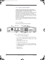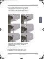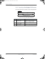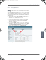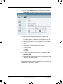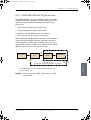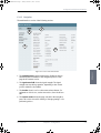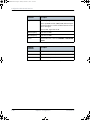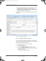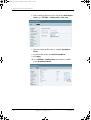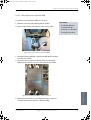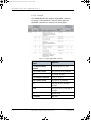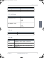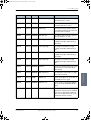
1
TRAINING, INSTALLATION & SERVICE MANUAL SAILOR 900 VSAT System SAILOR900TM.book Page i Tuesday, December 11, 2012 10:26 AM SAILOR 900 VSAT Training, installation and service manual Document number: 98-133966-E2 Release date: 11 December 2012 SAILOR900TM.book Page ii Tuesday, December 11, 2012 10:26 AM Disclaimer Any responsibility or liability for loss or damage in connection with the use of this product and the accompanying documentation is disclaimed by Thrane & Thrane. The information in this manual is provided for information purposes only, is subject to change without notice and may contain errors or inaccuracies. Manuals issued by Thrane & Thrane are periodically revised and updated. Anyone relying on this information should acquire the most current version e.g. from http://www.thrane.com or from the distributor. Thrane & Thrane is not responsible for the content or accuracy of any translations or reproductions, in whole or in part, of this manual from any other source. Copyright © 2012 Thrane & Thrane A/S. All rights reserved. Trademark acknowledgements • Thrane & Thrane is a registered trademark of Thrane & Thrane A/S in the European Union and the United States. • SAILOR is a registered trademark of Thrane & Thrane A/S in the European Union and the United States. • Windows is a registered trademark of Microsoft Corporation in the United States and other countries. • Other product and company names mentioned in this manual may be trademarks or trade names of their respective owners. GPL notification The software included in this product contains copyrighted software that is licensed under the GPL/LGPL. The verbatim licenses can be found online at: http://www.gnu.org/licenses/old-licenses/gpl-2.0.html http://www.gnu.org/licenses/old-licenses/lgpl-2.1.html You may obtain the complete corresponding source code from us for a period of three years after our last shipment of this product, which will be no earlier than 2021, by sending a money order or check for DKK 50 to: SW Technology/GPL Compliance, Thrane & Thrane A/S, Lundtoftegaardsvej 93D 2800 Lyngby DENMARK Please write "source for product SAILOR 900 VSAT" in the memo line of your payment. You may also find a copy of the source at http://www.thrane.com/foss. This offer is valid to anyone in receipt of this information. ii 98-133966-E2 SAILOR900TM.book Page iii Tuesday, December 11, 2012 10:26 AM Safety summary The following general safety precautions must be observed during all phases of operation, service and repair of this equipment. Failure to comply with these precautions or with specific warnings elsewhere in this manual violates safety standards of design, manufacture and intended use of the equipment. Thrane & Thrane A/S assumes no liability for the customer's failure to comply with these requirements. Microwave radiation hazards During transmission the Above Deck Unit (antenna) in this system radiates Microwave Power.This radiation may be hazardous to humans close to the Above Deck Unit. During transmission, make sure that nobody gets closer than the recommended minimum safety distance. The minimum safety distance to the Above Deck Unit reflector on the focal line is 30 m, based on a radiation level of 10 W/m2. No hazard exists >25° below the Above Deck Unit’s mounting plane. Refer to the drawing below. MICROWAVE RADIATION No personnel within safety distance Safety distance: 30 m, 10 W/m2 No-transmit zones In order to protect personnel no-transmit zones can be programmed. For further information see Blocking zones — azimuth and elevation on page 3-5. Distance to other equipment Do not move the Above Deck Unit closer to radars than the minimum safe distance specified in section Interference on page 3-13 — it may cause damage to the Above Deck Unit. 98-133966-E2 iii SAILOR900TM.book Page iv Tuesday, December 11, 2012 10:26 AM Compass Safe Distance: SAILOR 900 VSAT antenna or ADU (Above Deck Unit): min. 130 cm (IEC 945). SAILOR 900 VSAT ACU (Antenna Control Unit): min. 10 cm (IEC 945) Service User access to the interior of the ACU is prohibited. Only a technician authorized by Thrane & Thrane A/S may perform service - failure to comply with this rule will void the warranty. Access to the interior of the Above Deck Unit is allowed. Replacement of certain modules as described in Service & maintenance on page 9-1 and general service may only be performed by a technician authorized by Thrane & Thrane A/S. Do not service or adjust alone Do not attempt internal service or adjustments unless another person, capable of rendering first aid resuscitation, is present. Grounding, cables and connections To minimize shock hazard and to protect against lightning, the equipment chassis and cabinet must be connected to an electrical ground. The ACU must be grounded to the ship. For further grounding information refer to the Installation manual. Do not extend the cables beyond the lengths specified for the equipment. The cable between the ACU and Above Deck Unit can be extended if it complies with the specified data concerning cable losses etc. Rx and Tx cables for the SAILOR 900 VSAT system are shielded and should not be affected by magnetic fields. However, try to avoid running cables parallel to high power and AC/RF wiring as it might cause malfunction of the equipment. Power supply The voltage range for the SAILOR 900 VSAT is 20 — 32 VDC. Note that the Above Deck Unit is powered by the ACU. If a 24 VDC power bus is not available, an external 115/230 VAC to 28 VDC power supply can be used, for example a SAILOR 6080 Power Supply. Do not operate in an explosive atmosphere Do not operate the equipment in the presence of flammable gases or fumes. Operation of any electrical equipment in such an environment constitutes a definite safety hazard. Keep away from live circuits Operating personnel must not remove equipment covers. Component replacement and internal adjustment must be made by qualified maintenance personnel. Do not replace components with the power cable connected. Under certain conditions, dangerous voltages may exist even with the power cable removed. To avoid injuries, always disconnect power and discharge circuits before touching them. Failure to comply with the rules above will void the warranty! iv 98-133966-E2 SAILOR900TM.book Page v Tuesday, December 11, 2012 10:26 AM CAUTION! Do not manually turn the Polarisation Unit of the antenna, it may cause damage to the antenna. If needed to turn the Polarisation Unit manually, remove the connector (1) marked M of the Polarisation Motor Module (2). (1) (2) Remove M VSAT restrictions Note There are restrictions in use of the frequency band 13.75 to 14 GHz in the following countries: • Belgium • Hungary • Latvia • Malta • Slovakia Contact VSAT modem provider for local setups. 98-133966-E2 v SAILOR900TM.book Page vi Tuesday, December 11, 2012 10:26 AM vi 98-133966-E2 SAILOR900TM.book Page vii Tuesday, December 11, 2012 10:26 AM Table of contents Chapter 1 Chapter 2 About this manual 1.1 Intended readers ................................................................................ 1-1 1.2 Manual overview ............................................................................... 1-1 1.3 Software version ............................................................................... 1-2 1.4 Related documents ............................................................................ 1-2 1.5 Typography ....................................................................................... 1-2 1.6 Precautions ....................................................................................... 1-3 Introduction 2.1 SAILOR 900 VSAT system .................................................................. 2-1 2.1.1 Overview ......................................................................................... 2-1 2.1.2 Above Deck Unit (ADU) ....................................................................2-4 2.1.3 Antenna Control Unit (ACU) .............................................................2-8 2.1.4 VSAT Modem Unit (VMU) .............................................................. 2-10 2.1.5 Satellite type approvals ................................................................. 2-10 2.1.6 Power supply (optional) ................................................................ 2-10 2.1.7 Service activation .......................................................................... 2-10 2.2 Part numbers and options ................................................................ 2-11 2.2.1 Applicable Thrane & Thrane model and part numbers .................... 2-11 2.2.2 Options for SAILOR 900 VSAT ......................................................... 2-11 98-133966-E2 vii SAILOR900TM.book Page viii Tuesday, December 11, 2012 10:26 AM Table of contents Chapter 3 Installation 3.1 Unpacking .........................................................................................3-1 3.1.1 What’s in the box .............................................................................3-1 3.1.2 Initial inspection ............................................................................. 3-2 3.1.3 Tools needed .................................................................................. 3-3 3.2 3.2.1 3.2.2 3.2.3 3.2.4 3.2.5 3.2.6 3.2.7 3.2.8 Site preparation ................................................................................ 3-3 General site considerations ............................................................. 3-3 Obstructions (ADU shadowing) ....................................................... 3-4 Blocking zones — azimuth and elevation ......................................... 3-5 Safe access to the ADU: Radiation hazard ....................................... 3-6 Ship motion and offset from the ship’s motion centre ..................... 3-7 ADU mast design: Foundation and height .......................................3-8 Interference ...................................................................................3-13 Other precautions .......................................................................... 3-17 3.3 Installation of the ADU .....................................................................3-18 3.3.1 Installing the ADU ..........................................................................3-19 3.3.2 Opening and removing the service hatch ...................................... 3-22 3.3.3 Grounding the ADU ....................................................................... 3-23 3.3.4 Alternative ADU cable ................................................................... 3-25 3.4 Installation of the ACU (bulkhead) ................................................... 3-26 3.4.1 Installing the ACU (bulkhead) ....................................................... 3-26 3.4.2 Grounding the ACU (bulkhead) ..................................................... 3-27 3.4.3 SAILOR 900 VSAT ACU (bulkhead) with cable support ................... 3-28 3.5 Installation of the 19” rack version of the ACU ................................ 3-30 3.5.1 Installing the 19” rack version of the ACU ...................................... 3-30 3.5.2 Grounding the 19” rack version of the ACU .....................................3-31 3.6 Installation of the VMU ................................................................... 3-32 3.6.1 General mounting considerations — VMU ..................................... 3-32 3.7 viii Installing the dual-antenna mode (optional) ................................... 3-33 98-133966-E2 SAILOR900TM.book Page ix Tuesday, December 11, 2012 10:26 AM Table of contents Chapter 4 Chapter 5 Chapter 6 Interfaces 4.1 4.1.1 4.1.2 4.1.3 4.1.4 4.1.5 4.1.6 4.1.7 4.1.8 4.1.9 4.1.10 Interfaces of the SAILOR 900 VSAT ACU ............................................ 4-1 ACU bulkhead — LEDs, display and keypad ...................................... 4-1 ACU 19” rack version — LEDs, display and keypad ............................ 4-1 ACU bulkhead — Connector panel — overview ..................................4-2 ACU 19” rack version — Connector panel — overview ........................4-2 DC Input connector ..........................................................................4-3 ADU connector ................................................................................4-4 Rx/Tx connectors for VMU ..........................................................4-4 NMEA 0183 connector (RS-422) .......................................................4-5 RS-232 and RS-422 connectors .......................................................4-6 LAN1, LAN2, LAN3 and LAN4 connectors ..........................................4-7 4.2 4.2.1 4.2.2 4.2.3 4.2.4 4.2.5 Interfaces of the VMU .......................................................................4-9 Connecting an iNFINITI® Series Satellite Router .............................4-9 Connecting an Evolution® Satellite Router ................................... 4-10 Connecting a Comtech 570 L or 625 Satellite Modem .................... 4-10 Connecting a Satlink2900 VSAT modem ......................................... 4-11 Connecting a Gilat SkyEdge II VSAT modem .................................. 4-12 Connecting power 5.1 Power source .................................................................................... 5-1 5.2 5.2.1 5.2.2 5.2.3 Power cable selection .......................................................................5-2 Source impedance ...........................................................................5-2 Measuring the ship source impedance ............................................5-2 Power cable recommendations .......................................................5-3 5.3 Connecting power .............................................................................5-4 5.4 Power up ..........................................................................................5-5 Configuration 6.1 Introduction to the built-in web interface ......................................... 6-1 6.1.1 Overview ......................................................................................... 6-1 6.1.2 Connecting to the web interface ......................................................6-2 98-133966-E2 ix SAILOR900TM.book Page x Tuesday, December 11, 2012 10:26 AM Table of contents 6.2 6.2.1 6.2.2 6.2.3 6.2.4 6.2.5 Calibration of the SAILOR 900 VSAT .................................................. 6-4 Preparing for calibration ................................................................. 6-4 Heading and calibration of azimuth and cable ................................6-6 Flow chart for azimuth and cable calibration .................................6-10 Line up procedure .......................................................................... 6-11 SAILOR 900 VSAT fixed TX gain principle .......................................6-13 6.3 Configuration with the web interface ..............................................6-14 6.3.1 Overview and navigation ................................................................6-14 6.3.2 Using the Dashboard .....................................................................6-18 6.3.3 Satellite profiles and VSAT modem profiles ....................................6-21 6.3.4 Setting up Blocking zones (RX and TX) ......................................... 6-27 6.3.5 Configuring the LAN network ........................................................ 6-29 6.3.6 E-mail setup ................................................................................. 6-32 6.3.7 Sending statistics reports .............................................................. 6-33 6.3.8 Sending a diagnostics report ........................................................ 6-36 6.3.9 Dual antenna mode (optional) ...................................................... 6-37 6.3.10 Upload .......................................................................................... 6-42 6.3.11 Administration .............................................................................. 6-43 Chapter 7 6.4 6.4.1 6.4.2 6.4.3 6.4.4 6.4.5 Keypad and menus of the ACU ........................................................ 6-49 ACU display and keypad ............................................................... 6-49 Navigating the menus ...................................................................6-50 The menu tree ...............................................................................6-51 Adjusting brightness of the display ............................................... 6-54 Resetting the system ..................................................................... 6-55 6.5 SNMP support ................................................................................. 6-55 Installation check 7.1 Installation check list: Antenna ..........................................................7-1 7.2 Installation check list: ACU, connectors and wiring ........................... 7-3 7.3 Installation check list: Functional test in harbor ................................ 7-5 Chapter 8 Daily use — Quick guide Chapter 9 Service & maintenance 9.1 Getting support: Helpdesk ................................................................ 9-2 9.1.1 Help desk and diagnostic report ..................................................... 9-2 x 98-133966-E2 SAILOR900TM.book Page xi Tuesday, December 11, 2012 10:26 AM Table of contents 9.2 9.2.1 9.2.2 9.2.3 Software update .............................................................................. 9-5 Hardware and software requirements ............................................ 9-5 Software update (ADU and ACU) .................................................... 9-5 Verifying the software update ......................................................... 9-6 9.3 9.3.1 9.3.2 9.3.3 Status signalling with LEDs and status messages ............................. 9-8 Overview ........................................................................................ 9-8 LEDs of the ADU modules ............................................................... 9-9 LEDs in the ACU ............................................................................ 9-10 9.4 Removal and replacement of the ACU ............................................... 9-11 9.5 Removal and replacement of ADU modules ..................................... 9-12 9.5.1 Overview ....................................................................................... 9-12 9.5.2 Replacing the GPS module ............................................................ 9-18 9.5.3 Replacing the VSAT Interface Module (VIM) .................................. 9-21 9.5.4 Replacing the DC-Motor Driver Module (DDM) ..............................9-24 9.5.5 Replacing the Polarisation Motor Module (PMM) ..........................9-28 9.5.6 Replacing the Pedestal Control Module (PCM) ..............................9-32 9.5.7 Replacing motor and encoder .......................................................9-34 9.5.8 Replacing the Drive Belts ..............................................................9-55 9.5.9 Replacing the Zero Reference Module (ZRM) ................................9-63 9.5.10 Replacing the Inertial Sensor Module (ISM) ..................................9-70 9.5.11 Replacing the Polarisation Unit .....................................................9-73 9.5.12 Replacing the BUC Fan .................................................................. 9-77 9.5.13 Replacing the Block Up Converter (BUC) .......................................9-78 9.5.14 Replacing the Low Noise Block down converter (LNB) .................. 9-80 9.5.15 Replacing the Ortho Mode Transducer (OMT) ................................9-82 9.5.16 Replacing the rotary joint ..............................................................9-85 98-133966-E2 9.6 Updating VIM/PCM calibration data ................................................9-89 9.7 9.7.1 9.7.2 9.7.3 9.7.4 9.7.5 9.7.6 Troubleshooting .............................................................................. 9-91 Overview ....................................................................................... 9-91 Event list for troubleshooting ........................................................ 9-91 Diagnostic report for troubleshooting ............................................ 9-91 Troubleshooting — BUC .................................................................9-92 Troubleshooting — LNB .................................................................9-93 System block diagram (ADU) .........................................................9-93 xi SAILOR900TM.book Page xii Tuesday, December 11, 2012 10:26 AM Table of contents Appendix A Technical specifications A.1 SAILOR 900 VSAT system components .............................................. A-1 A.1.1 General specifications ..................................................................... A-1 A.1.2 ADU ................................................................................................A-2 A.1.3 ACU ................................................................................................A-4 A.1.4 Supported VSAT modems ................................................................A-5 A.2 A.2.1 A.2.2 A.2.3 A.2.4 Outline drawings ..............................................................................A-6 ADU ................................................................................................A-6 ACU, bulkhead ................................................................................A-7 ACU, 19 inch rack ........................................................................... A-8 N-connector interface on the ADU ..................................................A-9 A.3 VSAT LNB Data Sheet (physical LNB) ............................................... A-10 A.3.1 VSAT LNB user installation and configuration information ............ A-10 A.4 Appendix B Appendix C VSAT 8 W BUC Data Sheet (Extended) ............................................. A-12 VMU cable specifications B.1 Modem Cable Comtech Serial & RSSI TT7016A ..................................B-2 B.2 Modem Cable iNIFINITI iDirect VSAT modem ....................................B-3 VMU settings requirements C.1 Open AMIP setup for iDirect INFINITI & Evolution .............................C-2 C.1.1 Protocol and interfaces ...................................................................C-2 C.1.2 Sample options file .........................................................................C-5 C.1.3 Configuration examples (OpenAMIP) ..............................................C-8 C.2 C.2.1 C.2.2 C.2.3 Non-Open-AMIP setup for iDirect iNFINITI 5000 & Evolution X5 .......C-9 Protocol and interfaces ...................................................................C-9 Console port settings .....................................................................C-10 Configuration examples (Non-OpenAMIP) .....................................C-12 C.3 Comtech 570L, ROSS box & ACU .......................................................C-14 C.3.1 Protocols and interfaces .................................................................C-14 C.4 STM SatLink 2900 VSAT modem .......................................................C-15 C.4.1 Interfaces and VSAT modem configuration .....................................C-15 C.4.2 ACU configuration ..........................................................................C-16 xii 98-133966-E2 SAILOR900TM.book Page xiii Tuesday, December 11, 2012 10:26 AM Table of contents C.5 Gilat SkyEdge II VSAT modem ......................................................... C-17 C.5.1 Interfaces and VSAT modem configuration .................................... C-17 C.5.2 ACU configuration ......................................................................... C-18 Appendix D Command line interface D.1 Introduction ......................................................................................D-1 D.1.1 Telnet connection ........................................................................... D-2 D.1.2 Help ............................................................................................... D-2 D.1.3 Conventions ................................................................................... D-3 D.2 D.2.1 D.2.2 D.2.3 D.2.4 D.2.5 D.2.6 D.2.7 D.2.8 D.2.9 D.2.10 D.2.11 Supported commands ...................................................................... D-4 config ............................................................................................. D-4 demo ............................................................................................. D-4 dual_antenna ................................................................................. D-5 exit ................................................................................................. D-5 help ............................................................................................... D-5 modem ........................................................................................... D-6 satellite .......................................................................................... D-6 status ............................................................................................. D-9 system ............................................................................................ D-9 track ..............................................................................................D-10 zone ...............................................................................................D-11 Appendix E DVB-S satellites Appendix F Grounding and RF protection F.1 Why is grounding required? .............................................................. F-1 F.1.1 Reasons for grounding .................................................................... F-1 F.1.2 Safety .............................................................................................. F-1 F.1.3 ESD Protection ................................................................................ F-1 F.2 Grounding Recommendations ...........................................................F-2 F.2.1 Grounding the ACU .........................................................................F-2 F.2.2 Grounding the ADU .........................................................................F-3 F.3 Alternative grounding for steel hulls .................................................F-5 F.3.1 Grounding the ACU .........................................................................F-5 F.3.2 Grounding the ADU .........................................................................F-5 98-133966-E2 xiii SAILOR900TM.book Page xiv Tuesday, December 11, 2012 10:26 AM Table of contents F.4 Alternative grounding for aluminum hulls ........................................ F-7 F.4.1 Grounding the ACU ......................................................................... F-7 F.4.2 Grounding the ADU ......................................................................... F-7 F.5 Alternative grounding for fibre glass hulls .......................................F-9 F.5.1 Grounding the ACU .........................................................................F-9 F.5.2 Grounding the ADU ........................................................................F-10 F.6 F.6.1 F.6.2 F.6.3 Separate ground cable ..................................................................... F-11 Ground cable - construction .......................................................... F-11 Ground cable - connection .............................................................F-12 Isolation of the ADU from the mounting base .................................F-12 F.7 Jumper cable for grounding .............................................................F-14 F.8 RF interference ................................................................................F-15 F.8.1 Recommendations .........................................................................F-15 Appendix G Appendix H System messages G.1 Event messages — overview ............................................................. G-1 G.2 List of ADU events .............................................................................G-2 G.3 List of ACU events ............................................................................ G-9 Approvals H.1 Satellite approvals ............................................................................ H-1 H.2 CE (R&TTE) ........................................................................................ H-1 Glossary ............................................................................................................ Glossary-1 Index .................................................................................................................Index-1 xiv 98-133966-E2 SAILOR900TM.book Page xv Tuesday, December 11, 2012 10:26 AM List of figures Chapter 1 About this manual Chapter 2 Introduction Figure 2-1: Figure 2-2: Figure 2-3: Figure 2-4: Figure 2-5: Figure 2-6: Figure 2-7: Figure 2-8: Figure 2-9: Above Deck Unit and Antenna Control Unit (ACU).................................................2-2 Above Deck Unit and Antenna Control Unit (ACU), 19” rack version ......................2-2 Above Deck Unit (ADU) .........................................................................................2-4 Above Deck Unit modules 1/2............................................................................... 2-5 Above Deck Unit modules 2/2 .............................................................................. 2-6 SAILOR 900 VSAT ACU, connector overview ......................................................... 2-8 SAILOR 900 VSAT ACU, 19” rack version............................................................... 2-9 Antenna Control Unit for bulkhead installation.................................................... 2-9 Antenna Control Unit for 19” rack installation ...................................................... 2-9 Chapter 3 Installation Figure 3-1: Figure 3-2: Figure 3-3: Figure 3-4: Figure 3-5: Figure 3-6: Figure 3-7: Figure 3-8: Figure 3-9: Figure 3-10: Figure 3-11: Figure 3-12: Figure 3-13: Figure 3-14: Figure 3-15: Figure 3-16: Figure 3-17: Figure 3-18: Figure 3-19: Figure 3-20: Figure 3-21: Signal degradation because of obstructing objects ...............................................3-4 2 blocking zones with no-transmit zones, azimuth (example) .............................. 3-5 Blocking zone with no-transmit zones, elevation angle (example)....................... 3-5 Radiation hazard, safety distance 30 m ............................................................... 3-6 Maximum distance from the ship’s motion centre (h max)....................................3-7 ADU mast flange, top and side view..................................................................... 3-8 ADU mast flange, recommended flatness on the mast mount plateau.................. 3-8 ADU mast flange, distance to the welded seam ................................................... 3-9 ADU, bottom view................................................................................................ 3-9 Free mast length and bracing for a tall mast ...................................................... 3-10 Interference with the vessel’s radar .................................................................... 3-14 Recommended distance to transmitters (m) for frequencies below 1000 MHz ..... 3-16 Drain pipe with free space.................................................................................. 3-17 Use of strong sling with a belt and tag lines for safe hoisting ............................. 3-18 Free space for access to the service hatch........................................................... 3-19 ADU installation, webbed sling attached to the 4 lifting brackets........................3-20 Mounting the ADU on the mast flange................................................................3-20 Connecting the ADU cable .................................................................................. 3-21 Opening the service hatch ..................................................................................3-22 Removing the 2 split pins ...................................................................................3-22 Removing the service hatch................................................................................3-23 98-133966-E2 xv SAILOR900TM.book Page xvi Tuesday, December 11, 2012 10:26 AM List of figures Figure 3-22: Figure 3-23: Figure 3-24: Figure 3-25: Figure 3-26: Figure 3-27: Figure 3-28: Figure 3-29: Figure 3-30: Figure 3-31: Figure 3-32: Figure 3-33: ADU, bolt for optimum grounding ...................................................................... 3-24 SAILOR 900 VSAT ACU without cable support ..................................................... 3-26 ACU, connector panel......................................................................................... 3-26 SAILOR 900 VSAT ACU, bulkhead version, ground stud ...................................... 3-27 Cable relief for the ACU...................................................................................... 3-28 Mounting the cable relief 1/2.............................................................................. 3-28 Mounting the cable relief 2/2 ............................................................................. 3-29 ACU, 19” rack version, On/off switch at the back .................................................3-30 ACU, LAN connector at the front: Service port......................................................3-31 ACU, 19” rack version, ground stud .....................................................................3-31 Dual mode antenna, overview ............................................................................ 3-33 Dual mode antenna, connecting cables (example) ............................................. 3-34 Chapter 4 Interfaces Figure 4-1: Figure 4-2: Figure 4-3: Figure 4-4: Figure 4-5: Figure 4-6: Figure 4-7: Figure 4-8: Figure 4-9: Figure 4-10: Figure 4-11: ACU bulkhead, LEDs, display and keypad ..............................................................4-1 ACU rack version, LEDs, display and keypad..........................................................4-1 ACU bulkhead, connector panel overview.............................................................4-2 ACU rack version, connector panel overview ........................................................4-2 DC Input connector with power cable ...................................................................4-3 LAN1 —LAN4 connectors ....................................................................................... 4-7 Connecting an iNFINITI® Series Satellite Router..................................................4-9 Connecting an Evolution Satellite Router ............................................................4-10 Connecting a Comtech 570 L or 625 Satellite Modem ..........................................4-10 Connecting a SatLink 2900 Modem ..................................................................... 4-11 Connecting a Gilat SkyEdge II VSAT Modem ........................................................4-12 Chapter 5 Connecting power Figure 5-1: Figure 5-2: Figure 5-3: Measuring the ship source impedance.................................................................5-3 Connecting power to DC Input..............................................................................5-4 ACU display after first power on (example with LAN ports 1 and 4 used) ...............5-5 Chapter 6 Configuration Figure 6-1: Figure 6-2: Figure 6-3: Figure 6-4: Figure 6-5: Configuration setup.............................................................................................. 6-1 LAN connector used for configuring the SAILOR 900 VSAT ...................................6-2 SAILOR 900 VSAT Dashboard ...............................................................................6-3 Service profile for calibration ...............................................................................6-5 Web interface: SERVICE, Calibration.....................................................................6-6 xvi 98-133966-E2 SAILOR900TM.book Page xvii Tuesday, December 11, 2012 10:26 AM List of figures Figure 6-6: Figure 6-7: Figure 6-8: Figure 6-9: Figure 6-10: Figure 6-11: Figure 6-12: Figure 6-13: Figure 6-14: Figure 6-15: Figure 6-16: Figure 6-17: Figure 6-18: Figure 6-19: Figure 6-20: Figure 6-21: Figure 6-22: Figure 6-23: Figure 6-24: Figure 6-25: Figure 6-26: Figure 6-27: Figure 6-28: Figure 6-29: Figure 6-30: Figure 6-31: Figure 6-32: Figure 6-33: Figure 6-34: Figure 6-35: Figure 6-36: Figure 6-37: Figure 6-38: Figure 6-39: Figure 6-40: Figure 6-41: Figure 6-42: Example for azimuth and cable calibration — step by step .................................. 6-10 Web interface: SERVICE, Line up: Ready for activation ......................................... 6-11 Web interface: SERVICE, Line up: Antenna ready ................................................ 6-12 Fixed TX gain principle....................................................................................... 6-13 Topics in the web interface (SITE MAP)............................................................... 6-14 Sections of the web interface.............................................................................. 6-15 Web interface: DASHBOARD ............................................................................... 6-18 Web interface: SETTINGS - list of satellite profiles (example) .............................. 6-21 Web interface: SETTINGS, Satellite profiles — new entry (example) .....................6-22 Web interface: SETTINGS, VSAT modem profiles — list (example)........................6-24 Web interface: SETTINGS, VSAT modem profiles — new entry (example) .............6-25 Supported VSAT modems in software version 1.30 ..............................................6-25 Satellite profile for generic modem.....................................................................6-26 Web interface: SETTINGS, Blocking zones — azimuth and elevation ....................6-27 Blocking zone, example: 315 - 45 degrees ..........................................................6-28 Blocking zone, example: 45 - 315 degrees ..........................................................6-28 Web interface: SETTINGS, Network (default settings) ..........................................6-29 Web interface: SETTINGS, E-mail setup (example) ..............................................6-32 Web interface: SETTINGS, Reports (example)......................................................6-33 Statistics — how to read data for a range ............................................................6-35 Statistics report (example) ..................................................................................6-36 Dual-antenna mode, link on DASHBOARD..........................................................6-37 Enabling dual-antenna mode in Master ACU......................................................6-38 Dual-antenna mode, add Slave modem profile...................................................6-39 Dual-antenna mode, add Slave satellite profile ................................................. 6-40 Dual-antenna mode, Activate ............................................................................ 6-40 Dual-antenna mode, blocking zones — azimuth and elevation............................ 6-41 Dual-antenna mode, line up...............................................................................6-42 Web interface: Administration ............................................................................6-43 Web interface: Administration, change administrator logon and password.........6-44 Web interface: ADMINISTRATION, Reset administrator password .......................6-44 Web interface: ADMINISTRATION, User permissions...........................................6-45 Web interface: Administration, Export/import configuration ...............................6-46 Web interface: ADMINISTRATION, Factory default ..............................................6-48 Display (example) and keypad of the ACU...........................................................6-49 Antenna Control Unit, menu tree ........................................................................ 6-51 Reset the system................................................................................................ 6-55 98-133966-E2 xvii SAILOR900TM.book Page xviii Tuesday, December 11, 2012 10:26 AM List of figures Chapter 7 Installation check Chapter 8 Daily use — Quick guide Figure 8-1: Figure 8-2: SAILOR 900 VSAT Quick Guide — web interface and satellite profiles.................... 8-1 SAILOR 900 VSAT Quick Guide — Viewing system parameters...............................8-2 Chapter 9 Service & maintenance Figure 9-1: Figure 9-2: Figure 9-3: Figure 9-4: Figure 9-5: Figure 9-6: Figure 9-7: Figure 9-8: Figure 9-9: Figure 9-10: Figure 9-11: Figure 9-12: Figure 9-13: Figure 9-14: Figure 9-15: Figure 9-16: Figure 9-17: Figure 9-18: Figure 9-19: Figure 9-20: Figure 9-21: Figure 9-22: Figure 9-23: Figure 9-24: Figure 9-25: Figure 9-26: Figure 9-27: Figure 9-28: Figure 9-29: Figure 9-30: Web interface: HELPDESK.....................................................................................9-2 Web interface: HELPDESK, Event list.....................................................................9-3 LAN connector used for configuring the SAILOR 900 VSAT ...................................9-5 Verifying software update ....................................................................................9-7 LEDs on the ACU ................................................................................................ 9-10 LEDs on the ACU, 19” rack version ...................................................................... 9-10 Removal and replacement of the ACU bulkhead .................................................. 9-11 Removal and replacement of the ACU 19” rack .................................................... 9-11 ADU modules and motor stop switch...................................................................9-12 Service switch .....................................................................................................9-16 Above Deck Unit modules (continued).................................................................9-17 GPS module ........................................................................................................9-18 Switch off the power to the antenna....................................................................9-19 GPS module facing the service hatch...................................................................9-19 Connector for GPS PCB.......................................................................................9-20 Screws on GPS module.......................................................................................9-20 VSAT Interface Module (VIM) ..............................................................................9-21 Location of the VIM .............................................................................................9-21 Replacing the VIM — remove 2 F-connectors ...................................................... 9-22 Replacing the VIM — remove 2 N, 2 F, 1 SMA and 1 SUB-D connectors ................ 9-22 Replacing the VIM — remove 4 Allen screws....................................................... 9-23 DC-Motor Driver Module (DDM) for Cross Elevation............................................ 9-24 Location of the Cross Elevation DDM .................................................................. 9-25 Replacing the DDM — remove connectors.......................................................... 9-25 Location of the Elevation DDM............................................................................ 9-26 Elevation DDM, connectors................................................................................. 9-26 location of the Azimuth DDM.............................................................................. 9-27 Azimuth DDM, connectors ..................................................................................9-28 Polarisation Motor Module, remove connectors .................................................9-29 Polarisation Motor Module, remove screws........................................................9-30 xviii 98-133966-E2 SAILOR900TM.book Page xix Tuesday, December 11, 2012 10:26 AM List of figures Figure 9-31: Figure 9-32: Figure 9-33: Figure 9-34: Figure 9-35: Figure 9-36: Figure 9-37: Figure 9-38: Figure 9-39: Figure 9-40: Figure 9-41: Figure 9-42: Figure 9-43: Figure 9-44: Figure 9-45: Figure 9-46: Figure 9-47: Figure 9-48: Figure 9-49: Figure 9-50: Figure 9-51: Figure 9-52: Figure 9-53: Figure 9-54: Figure 9-55: Figure 9-56: Figure 9-57: Figure 9-58: Figure 9-59: Figure 9-60: Figure 9-61: Figure 9-62: Figure 9-63: Figure 9-64: Figure 9-65: Figure 9-66: Figure 9-67: Polarisation Motor Module, inserting ................................................................. 9-31 Location of the PCM............................................................................................9-32 Removing the PCM — connectors .......................................................................9-33 Motors and encoders..........................................................................................9-34 Location of the Elevation Motor & Encoder .........................................................9-35 Elevation motor and encoder, loosen the belt tensioner .....................................9-35 Elevation Motor and Encoder, adjust belt tension ...............................................9-36 Elevation DDM, disconnect 2 connectors.............................................................9-36 Elevation motor and encoder, loosen the screws for the motor assembly............9-37 Elevation motor and encoder, tighten the screws for the motor assembly .......... 9-38 Elevation motor and encoder, adjust belt tension .............................................. 9-38 Elevation motor and encoder, check of belt tension............................................9-39 Elevation motor and encoder, loosen the belt tensioner .....................................9-39 Azimuth motor, remove cover ............................................................................. 9-41 Azimuth motor, loosen the belt tensioner ........................................................... 9-41 Azimuth motor, adjust belt tension.....................................................................9-42 Azimuth DDM, disconnect connector ..................................................................9-42 Azimuth motor, loosen the screws for the motor assembly .................................9-43 Azimuth motor, tighten the screws for the motor assembly.................................9-44 Azimuth motor, adjust belt tension.....................................................................9-44 Azimuth motor, tighten the belt tensioner ..........................................................9-45 Azimuth encoder, remove cover..........................................................................9-46 Azimuth DDM, disconnect connector ..................................................................9-46 Azimuth encoder, remove...................................................................................9-47 Azimuth encoder, adjust belt tension..................................................................9-47 Azimuth Encoder, adjust belt tension ................................................................ 9-48 Azimuth motor, tighten the belt tensioner ......................................................... 9-48 Replacement of X-Elevation Motor & Encoder 1 .................................................9-49 X-Elevation Motor & Encoder — belt tension/adjustment screw ......................... 9-50 Cross Elevation motor assembly, 4 Allen screws ................................................ 9-50 Cross Elevation motor assembly, do not tighten screws ...................................... 9-51 X-Elevation Motor & Encoder — adjust belt tension ............................................ 9-51 Belt tension in 3 positions ..................................................................................9-52 Cross Elevation motor assembly, tighten screws .................................................9-52 Polarisation Motor, disconnecting power............................................................9-53 Polarisation Motor, removing 4x4 mm Allen screws............................................9-53 Removing the sub-D connector of the PMM........................................................9-54 98-133966-E2 xix SAILOR900TM.book Page xx Tuesday, December 11, 2012 10:26 AM List of figures Figure 9-68: Figure 9-69: Figure 9-70: Figure 9-71: Figure 9-72: Figure 9-73: Figure 9-74: Figure 9-75: Figure 9-76: Figure 9-77: Figure 9-78: Figure 9-79: Figure 9-80: Figure 9-81: Figure 9-82: Figure 9-83: Figure 9-84: Figure 9-85: Figure 9-86: Figure 9-87: Figure 9-88: Figure 9-89: Figure 9-90: Figure 9-91: Figure 9-92: Figure 9-93: Figure 9-94: Figure 9-95: Figure 9-96: Figure 9-97: Figure 9-98: Figure 9-99: Figure 9-100: Figure 9-101: Figure 9-102: Figure 9-103: Figure 9-104: xx Polarisation Encoder, removing ......................................................................... 9-54 Location of the X Elevation Drive Belt.................................................................9-55 Removing the cable drum ..................................................................................9-56 Location of the Elevation Drive Belt .................................................................... 9-57 Elevation Drive Belt............................................................................................ 9-57 Elevation motor and encoder, loosen the belt tensioner .....................................9-58 Elevation motor and encoder, adjust belt tension...............................................9-58 Elevation Drive Belt............................................................................................9-59 Azimuth drive modules, remove cover................................................................9-60 Azimuth drive belt, loosen the belt tensioner ......................................................9-61 Azimuth drive belt, adjust belt tension ................................................................9-61 Getting access to the azimuth drive wheel.......................................................... 9-62 Azimuth Drive Belt ............................................................................................. 9-62 Zero Reference Modules (ZRM), location ........................................................... 9-63 Zero Reference Module (ZRM) ........................................................................... 9-63 X Elevation ZRM, disconnect connector..............................................................9-65 X Elevation ZRM, slide out .................................................................................9-65 Elevation ZRM, disconnect connector .................................................................9-66 Elevation ZRM, remove screws ........................................................................... 9-67 Azimuth ZRM, remove cover...............................................................................9-68 Azimuth ZRM, disconnect connector ..................................................................9-68 Azimuth ZRM, disconnect connector ..................................................................9-69 Polarisation ZRM, disconnecting........................................................................9-69 Polarisation ZRM, loosen 2x4 mm Allen screws.................................................. 9-70 Inertial Sensor Module (ISM), location ............................................................... 9-70 Inertial Sensor Module (ISM) ..............................................................................9-71 Removing the ISM.............................................................................................. 9-72 Removing the ISM Sub D connectors.................................................................. 9-72 Removing the sub-D connector of the PMM ....................................................... 9-74 Disconnecting the LNBs...................................................................................... 9-75 Removing the cable spool .................................................................................. 9-75 Disconnecting the OMT connector ...................................................................... 9-76 Disconnecting the OMT connector ...................................................................... 9-76 Removing the BUC fan ....................................................................................... 9-77 Block Up Converter (BUC), location .................................................................... 9-78 Block Up Converter (BUC)................................................................................... 9-78 BUC, removing ................................................................................................... 9-79 98-133966-E2 SAILOR900TM.book Page xxi Tuesday, December 11, 2012 10:26 AM List of figures Figure 9-105: Figure 9-106: Figure 9-107: Figure 9-108: Figure 9-109: Figure 9-110: Figure 9-111: Figure 9-112: Figure 9-113: Figure 9-114: Figure 9-115: Figure 9-116: Figure 9-117: Figure 9-118: Figure 9-119: Figure 9-120: Figure 9-121: Figure 9-122: Figure 9-123: Figure 9-124: Figure 9-125: BUC, removing (continued).................................................................................9-79 Low Noise Block (LNB)....................................................................................... 9-80 LNB, removing.................................................................................................... 9-81 LNB, removing (continued)................................................................................. 9-81 Ortho Mode Transducer (OMT)........................................................................... 9-82 OMT, removing 2xTorx20 screws on top............................................................. 9-83 OMT, removing 4xTorx20 screws on the left-hand rail of the Polarisation Unit... 9-83 OMT, removing 4xTorx20 screws on the right-hand rail of the Polarisation Unit 9-84 OMT, removing .................................................................................................. 9-84 OMT, removing the waveguide .......................................................................... 9-85 Rotary joint........................................................................................................ 9-85 Azimuth motor, remove cover ............................................................................ 9-86 Getting access to the azimuth drive wheel ..........................................................9-87 Rotary joint (in place) .........................................................................................9-87 Rotary joint (removed)....................................................................................... 9-88 Updating VIM/PCM calibration data (example) .................................................. 9-89 XIM data, warning............................................................................................. 9-89 XIM data not ready............................................................................................ 9-90 XIM data valid ................................................................................................... 9-90 Troubleshooting — BUC ......................................................................................9-92 Troubleshooting — LNB.......................................................................................9-93 App. A Technical specifications Figure A-1: Figure A-2: Figure A-3: Figure A-4: Outline drawing: ADU.......................................................................................... A-6 Outline drawing: ACU, bulkhead.......................................................................... A-7 Outline drawing: ACU, 19 inch rack ...................................................................... A-8 N-Connector interface on the ADU....................................................................... A-9 App. B VMU cable specifications Figure B-1: Figure B-2: Modem Cable Comtech Serial & RSSI TT7016A .................................................... B-2 Modem Cable iNIFINITI iDirect VSAT modem ...................................................... B-3 App. C VMU settings requirements Figure C-1: Figure C-2: Figure C-3: Figure C-4: Connecting iDirect iNFINITI 5000 series to the ACU (OpenAMIP) ......................... C-3 Connecting iDirect Evolution X5 to the ACU (OpenAMIP) ..................................... C-3 Supported OpenAMIP commands ........................................................................ C-4 VSAT modem profile, OpenAMIP (example) ......................................................... C-8 98-133966-E2 xxi SAILOR900TM.book Page xxii Tuesday, December 11, 2012 10:26 AM List of figures Figure C-5: Figure C-6: Figure C-7: Figure C-8: Figure C-9: Figure C-10: Figure C-11: Figure C-12: Figure C-13: Satellite profile, OpenAMIP (example)..................................................................C-8 Connecting iDirect iNFINITI 5000 series to the ACU (Non-OpenAMIP) ..................C-9 Connecting iDirect Evolution X5 to the ACU (Non-OpenAMIP) ............................ C-10 RS-232 Console cable for iDirect Non-OpenAMIP VSAT modem.......................... C-10 VSAT modem profile, Non-OpenAMIP (example) .................................................C-12 Satellite profile, Non-OpenAMIP (example).........................................................C-13 Connecting Comtech 570L and ROSS box to the ACU (example)...........................C-14 Connecting SatLink 2900 VSAT modem to the ACU ..............................................C-15 Connecting Gilat SkyEdge II VSAT modem to the ACU..........................................C-17 App. D Command line interface Figure D-1: Figure D-2: How to use the command line interface (example for telnet) ................................ D-1 Command line interface, login ............................................................................ D-2 App. E DVB-S satellites Figure E-1: Satellite data, example from www.lyngsat.com ....................................................E-2 App. F Grounding and RF protection Figure F-1: Figure F-2: Figure F-3: Figure F-4: Figure F-5: Figure F-6: Figure F-7: Figure F-8: Figure F-9: Extending the ground plane.................................................................................F-3 Grounding the ADU..............................................................................................F-3 Grounding at a dedicated RF ground (alternative)................................................F-6 Alternative grounding for aluminium hulls...........................................................F-8 Alternative grounding for fibreglass hulls ...........................................................F-10 Separate ground cable ........................................................................................ F-11 Isolation of the ADU from the mounting base......................................................F-12 ADU isolation and grounding cable.....................................................................F-13 Jumper cable for grounding (specifications) ........................................................F-14 App. G System messages App. H Approvals xxii 98-133966-E2 SAILOR900TM.book Page xxiii Tuesday, December 11, 2012 10:26 AM List of tables Chapter 1 About this manual Table 1-1: List of Related Documents .................................................................................... 1-2 Chapter 2 Introduction Table 2-1: Table 2-2: Model and part numbers for the SAILOR 900 VSAT system (T&T units)................. 2-11 Model and part numbers for options of the SAILOR 900 VSAT system .................. 2-11 Chapter 3 Installation Table 3-1: Table 3-2: Table 3-3: Table 3-4: Table 3-5: Table 3-6: Table 3-7: Table 3-8: Maximum distance from the ship’s motion center versus ship’s roll period...........3-7 Mast dimensions without braces ......................................................................... 3-11 Mast dimensions with 3 braces............................................................................ 3-11 Mast dimensions with 2 braces........................................................................... 3-12 Minimum radar separation, X-band ................................................................... 3-14 Minimum radar separation, S-band.................................................................... 3-15 ADU cable types and maximum lengths..............................................................3-25 Dual mode antenna, cabling...............................................................................3-34 Chapter 4 Interfaces Table 4-1: Table 4-2: Table 4-3: Table 4-4: Table 4-5: Table 4-6: Table 4-7: Table 4-8: Table 4-9: Table 4-10: Table 4-11: DC Input plug, outline and pin assignment...........................................................4-3 N connector, outline and pin assignment .............................................................4-4 F connector, Rx and Tx, outline and pin assignment.............................................4-4 NMEA 0183/2000 connector, outline and pin assignment .................................... 4-5 RS-232 connector, male, outline and pin assignment .......................................... 4-6 RS-422 connector, male, outline and pin assignment ...........................................4-7 Ethernet connector, outline and pin assignment.................................................. 4-8 Cables to connect an iNFINITI® Series Satellite Router ....................................... 4-9 Cables to connect a Comtech 570 L-Band Satellite Modem ................................. 4-10 Cables to connect a SatLink 2900 VSAT modem ................................................... 4-11 Cables to connect a Gilat SkyEdge VSAT modem................................................. 4-12 Chapter 5 Connecting power Chapter 6 Configuration Table 6-1: Table 6-2: Satellite requirements for elevation and carrier................................................... 6-5 Satellite identifier and NID values........................................................................ 6-8 98-133966-E2 xxiii SAILOR900TM.book Page xxiv Tuesday, December 11, 2012 10:26 AM List of tables Table 6-3: Table 6-4: Table 6-5: Table 6-6: Table 6-7: Table 6-8: Table 6-9: Table 6-10: Table 6-11: Table 6-12: Table 6-13: Table 6-14: Table 6-15: Table 6-16: Table 6-17: Possible error codes during calibration ................................................................6-9 Web interface: Event icon....................................................................................6-16 Web interface, DASHBOARD, SAILOR 900 VSAT parameters ...............................6-19 Web interface, DASHBOARD, VSAT MODEM parameter......................................6-20 Web interface, DASHBOARD, POINTING parameter............................................6-20 Elevation cutoff (in degrees) versus VSAT modem bandwidth and power ........... 6-23 Setup of LAN connectors ...................................................................................6-30 Statistics report, header record .......................................................................... 6-34 Parameters recorded in a statistics report .......................................................... 6-34 Top-level menus of the ACU ............................................................................... 6-52 ANTENNA menu of the ACU................................................................................ 6-52 MODEM menu of the ACU................................................................................... 6-53 NETWORK menu of the ACU ............................................................................... 6-53 SATELLITE menu of the ACU ............................................................................... 6-53 EVENTS menu of the ACU ................................................................................... 6-54 Chapter 7 Installation check Table 7-1: Table 7-2: Table 7-3: Installation check list: Antenna .............................................................................7-1 Installation check list: ACU, connectors and wiring .............................................. 7-3 Installation check list: Functional test in harbour ................................................. 7-5 Chapter 8 Daily use — Quick guide Chapter 9 Service & maintenance Table 9-1: Table 9-2: LEDs of the ADU modules .....................................................................................9-9 LEDs on the ACU ................................................................................................ 9-10 App. A Technical specifications Table A-1: Table A-2: Table A-3: Table A-4: Table A-5: Table A-6: Table A-7: General specifications .......................................................................................... A-1 Technical specifications for the Above Deck Unit ................................................. A-2 Technical specifications for the ACU .................................................................... A-4 Supported VSAT modems .................................................................................... A-5 Technical specifications for VSAT LNB ................................................................ A-10 4-band switching ................................................................................................ A-11 Technical specifications for VSAT 8 W BUC ......................................................... A-12 xxiv 98-133966-E2 SAILOR900TM.book Page xxv Tuesday, December 11, 2012 10:26 AM List of tables App. B VMU cable specifications App. C VMU settings requirements Table C-1: Table C-2: Table C-3: Table C-4: Table C-5: Table C-6: Messages sent from the VSAT modem to the ACU (examples) .............................. C-4 Messages sent from the ACU to the VSAT modem (examples) .............................. C-5 Ranges for signal strength for iDirect Open AMIP VSAT modem........................... C-5 Information in the VSAT modem option file ......................................................... C-7 Requirements for VSAT modem option file, Non-OpenAMIP ................................ C-11 Configuration of Gilat SkyEdge II VSAT modem................................................... C-18 App. D Command line interface Table D-1: Table D-2: Table D-3: Table D-4: Table D-5: Table D-6: Table D-7: Table D-8: Table D-9: Table D-10: Table D-11: Table D-12: Command typography.......................................................................................... D-3 UCLI command: config................................. D-4 UCLI command: demo................................... D-4 UCLI command: dual_antenna........................... D-5 UCLI command: exit................................... D-5 UCLI command: help................................... D-5 UCLI command: modem.................................. D-6 UCLI command: satellite.............................. D-6 UCLI command: status................................. D-9 UCLI command: system................................. D-9 UCLI command: track................................. D-10 UCLI command: zone.................................. D-11 App. E DVB-S satellites Table E-1: Examples of DVB-S satellites for azimuth calibration ............................................ E-1 App. F Grounding and RF protection App. G System messages Table G-1: Table G-2: ADU event messages ........................................................................................... G-2 ACU event messages ........................................................................................... G-9 App. H Approvals 98-133966-E2 xxv SAILOR900TM.book Page xxvi Tuesday, December 11, 2012 10:26 AM List of tables xxvi 98-133966-E2 SAILOR900TM.book Page 1 Tuesday, December 11, 2012 10:26 AM 1111 About this manual 1.1 About this manual Chapter 1 1 Intended readers This is an installation and user manual for the SAILOR 900 VSAT system, intended for installers of the system and service personnel. Personnel installing or servicing the system must be properly trained and authorized by Thrane & Thrane. It is important that you observe all safety requirements listed in the beginning of this manual, and install the system according to the guidelines in this manual. For daily use of the SAILOR 900 VSAT system see the SAILOR 900 VSAT Quick guide or Daily use — Quick guide on page 8-1. 1.2 Manual overview This manual has the following chapters: • Introduction • Installation • Interfaces • Connecting power • Configuration • Installation check • Daily use — Quick guide • Service & maintenance This manual has the following appendices: • Technical specifications • VMU cable specifications • VMU settings requirements • Command line interface • DVB-S satellites • Grounding and RF protection • System messages • Approvals 98-133966-E2 1-1 SAILOR900TM.book Page 2 Tuesday, December 11, 2012 10:26 AM Software version 1.3 Software version This manual is intended for SAILOR 900 VSAT with software version 1.30. 1.4 Related documents The following related documentation is referred to in this manual: Document number Title 98-133401 SAILOR 900 VSAT Quick guide 98-133400 Installation and user manual Table 1-1: List of Related Documents 1.5 Typography In this manual, typography is used as indicated below: Bold is used for the following purposes: • To emphasize words. Example: “Do not touch the antenna”. • To indicate what the user should select in the user interface. Example: “Select SETTINGS > LAN”. Italic is used to emphasize the paragraph title in cross-references. Example: “For further information, see Connecting Cables on page...”. 1-2 Chapter 1: About this manual 98-133966-E2 SAILOR900TM.book Page 3 Tuesday, December 11, 2012 10:26 AM 1111 Precautions Precautions About this manual 1.6 1.6.0.1 Warnings, Cautions and Notes Text marked with “Warning”, “Caution”, “Note” or “Important” show the following type of data: • Warning: A Warning is an operation or maintenance procedure that, if not obeyed, can cause injury or death. • Caution: A Caution is an operation or maintenance procedure that, if not obeyed, can cause damage to the equipment. • Note: A Note gives information to help the reader. • Important: A text marked Important gives information that is important to the user, e.g. to make the system work properly. This text does not concern damage on equipment or personal safety. 1.6.0.2 General precautions All personnel who operate equipment or do maintenance as specified in this manual must know and follow the safety precautions. The warnings and cautions that follow apply to all parts of this manual. WARNING! Before using any material, refer to the manufacturers’ material safety data sheets for safety information. Some materials can be dangerous. CAUTION! Do not use materials that are not equivalent to materials specified by Thrane & Thrane. Materials that are not equivalent can cause damage to the equipment. CAUTION! The system contains items that are electrostatic discharge sensitive. Use approved industry precautions to keep the risk of damage to a minimum when you touch, remove or insert parts or assemblies. 98-133966-E2 Chapter 1: About this manual 1-3 SAILOR900TM.book Page 4 Tuesday, December 11, 2012 10:26 AM Precautions 1-4 Chapter 1: About this manual 98-133966-E2 SAILOR900TM.book Page 1 Tuesday, December 11, 2012 10:26 AM 2222 Chapter 2 Introduction 2 Introduction This chapter is organised in the following sections: • SAILOR 900 VSAT system • Part numbers and options 2.1 SAILOR 900 VSAT system 2.1.1 Overview The SAILOR 900 VSAT is a unique stabilized maritime VSAT antenna system operating in the Ku-band (10.7 to 14.5 GHz). It provides bidirectional IP data connections both on regional satellite beams and quasi-global Ku-band satellite networks. The system only requires a single 50 Ohm cable to provide the Above Deck Unit with both DC power, data and control information. The radome does not have to be removed neither before nor after the installation. To protect the Above Deck Unit the built-in DC motors act as breaks during transport and when the Above Deck Unit is not powered. The ADU system can be accessed remotely and in-depth performance analysis can be done using the built-in web interface. The SAILOR 900 VSAT system consists of two units: • Above Deck Unit (ADU) • Antenna Control Unit (ACU) 98-133966-E2 2-1 SAILOR900TM.book Page 2 Tuesday, December 11, 2012 10:26 AM SAILOR 900 VSAT system The following figures show the SAILOR 900 VSAT system with its two variants of ACUs. Above Deck Unit (ADU) Antenna Control Unit (ACU) Figure 2-1: Above Deck Unit and Antenna Control Unit (ACU) Above Deck Unit (ADU) Antenna Control Unit (ACU) (1 U 19” rack mount) Figure 2-2: Above Deck Unit and Antenna Control Unit (ACU), 19” rack version 2-2 Chapter 2: Introduction 98-133966-E2 SAILOR900TM.book Page 3 Tuesday, December 11, 2012 10:26 AM 2222 SAILOR 900 VSAT system 2.1.1.1 SAILOR 900 VSAT features Single 50 Ohm coax cable for the ADU. Support of several VSAT modems. Introduction Dual antenna mode1. SNMP support. Service communication using SAILOR FleetBroadband over WAN. Remote or local simultaneous software update of ADU and ACU via PC and Internet browser. Global RF configuration. Full remote control and troubleshooting with built-in test equipment (BITE). ACU with 4 x LAN, NMEA 0183, NMEA 2000, RS-232 and RS-422. All interfaces at the ACU, no additional units required. DC powered. Start up voltage: 22 VDC guaranteed, operating range: 20 — 32 VDC. No scheduled maintenance. 1. Patent pending. 98-133966-E2 Chapter 2: Introduction 2-3 SAILOR900TM.book Page 4 Tuesday, December 11, 2012 10:26 AM SAILOR 900 VSAT system 2.1.2 Above Deck Unit (ADU) The SAILOR 900 VSAT ADU is a 103 cm VSAT stabilised tracking antenna, consisting of a suspended antenna with a standard global RF configuration. The ADU’s weight is 135 kg. It is stabilized by heavy duty vibration dampers in 3-axis (plus skew) and can be used in environments with elevations of -25° to + 125°. The ADU is powered by the ACU and protected by a radome. Figure 2-3: Above Deck Unit (ADU) 2-4 Chapter 2: Introduction 98-133966-E2 SAILOR900TM.book Page 5 Tuesday, December 11, 2012 10:26 AM 2222 SAILOR 900 VSAT system Introduction 2.1.2.1 Modules in the SAILOR 900 VSAT ADU Figure 2-4: Above Deck Unit modules 1/2 1. GPS module. 2. VSAT Interface Module (VIM). 3. DC-Motor Driver Module for cross elevation (DDM). 4. Cross elevation motor and encoder. 5. Zero Reference Module (x4) (ZRM) (not visible on photo). 6. DC-Motor Driver Module for elevation (on the bottom) (DDM). 7. Elevation motor and encoder (not visible). 8. Polarisation Motor Module (PMM). 98-133966-E2 Chapter 2: Introduction 2-5 SAILOR900TM.book Page 6 Tuesday, December 11, 2012 10:26 AM SAILOR 900 VSAT system 9. Polarisation motor. 10. Polarisation encoder (not visible on photo). 11. Block Up Converter (BUC). (behind cable screen, not visible on photo) 12. Low Noise Block downconverter (x2) (LNB). 13. Ortho Mode Transducer (OMT). (not visible on photo) 14. Inertial Sensor Module (ISM). 15. Elevation locking pin to lock the antenna dish in a fixed position. 16. Pedestal Control Module (PCM). 17. Service switch. In switch-off position the DC Motor Driver modules and the BUC are turned off for safe conditions during service and repair. The switch must be in on position for normal ADU operation. Figure 2-5: Above Deck Unit modules 2/2 18. DC-Motor Driver Module for Azimuth (DDM). 19. Azimuth motor. 20.Azimuth encoder. 2-6 Chapter 2: Introduction 98-133966-E2 SAILOR900TM.book Page 7 Tuesday, December 11, 2012 10:26 AM 2222 SAILOR 900 VSAT system 21. Rotary joint. 22.Feed horn. See Overview on page 9-12 in the chapter Service & maintenance for a more detailed description of the modules. Introduction 2.1.2.2 SAILOR 900 VSAT ADU interface All communication between the ADU and the ACU passes through a single standard 50 Ohm cable (with N connector) through the rotary joint. No cable work is required inside the radome. 2.1.2.3 Installation friendly Four lifting brackets (included in the delivery) and reuse of packing material help getting the ADU safely into place. Satellite profile parameters are entered using the built-in web server of the ACU, using a PC. The included cable relief support can be attached to the ACU. 2.1.2.4 Service friendly The system configuration is saved in two modules, there is no loss of data at repair. The large service hatch of the radome gives easy access to the ADU on site. The service switch in the ADU stops the DC Motor Driver modules and turns the BUC off. The service tools for replacing modules are placed on a tool holder inside the radome. All modules have a service and power LED status indicator. Each module is encapsulated in a metal box with self-contained mounting bolts. If necessary, belts and modules can be exchanged through the service hatch on site. You can do remote diagnostics and service with the ADU. Its built-in test equipment checks constantly the ADU’s components for proper functioning, it monitors and logs information for all modules. The ADU performs a POST (Power On Self Test) and you can request a self test (Person Activated Self Test) and Continuous Monitoring (CM). Error codes can be read out in the web interface and in the display of the ACU. ADU software is updated automatically when making a software update of the ACU. 98-133966-E2 Chapter 2: Introduction 2-7 SAILOR900TM.book Page 8 Tuesday, December 11, 2012 10:26 AM SAILOR 900 VSAT system 2.1.3 Antenna Control Unit (ACU) The ACU is the central unit in the system. It contains all user interfaces and manages all communication between the ADU and connected the VMU, a connected PC and an optional FleetBroadband service communication line. The ACU has a display, status LEDs and a keypad. It provides a DHCP client. During configuration you can configure heading offset, save satellite and VMU setups and enter No Transmit Zones (blocking zones in which the ADU does not transmit). The ACU provides DC power to the ADU through a single coaxial cable. You can use the SAILOR 6080 Power Supply to provide the DC power for the ACU. 2.1.3.1 ACU interfaces The ACU has the following interfaces and switch: ADU Rx Out Tx in RS-422 LAN 1 Modem Ctrl. LAN 2 Modem Ctrl. mm2. NMEA RS-232 LAN 3 LAN 4 Service port Power On/Off Figure 2-6: SAILOR 900 VSAT ACU, connector overview • N-connector for ADU cable (50 Ohm). • 2 x F connectors for Rx and Tx cables (75 Ohm) to VSAT modem. • Multi connector for NMEA interfaces (for input from GPS compass or Gyro compass). • RS-422 interface for modem control. • RS-232 interface for modem control. • 4 x LAN ports for VSAT modem control and user equipment (i.e. for SAILOR FleetBroadband service communication line or WAN port for VSAT Internet). • Power connector. • On/Off power switch 2-8 Chapter 2: Introduction 98-133966-E2 SAILOR900TM.book Page 9 Tuesday, December 11, 2012 10:26 AM 2222 SAILOR 900 VSAT system The 19” rack version of the ACU has additionally a LAN connector at the front for accessing the service port from the ACU front panel. Introduction Service port Figure 2-7: SAILOR 900 VSAT ACU, 19” rack version 2.1.3.2 Installation friendly The ACU comes in two models: Wall or desktop installation (bulkhead) or in a 19” rack version. Figure 2-8: Antenna Control Unit for bulkhead installation Figure 2-9: Antenna Control Unit for 19” rack installation 98-133966-E2 Chapter 2: Introduction 2-9 SAILOR900TM.book Page 10 Tuesday, December 11, 2012 10:26 AM SAILOR 900 VSAT system 2.1.3.3 Service friendly You can do remote diagnostics and service with the ACU. Its built-in test equipment checks constantly the ACU’s modules for proper functioning, it monitors and logs for all modules. It performs POST (Power On Self Test) and you can request a PAST (Person Activated Self Test). Continuous Monitoring (CM) is also available. BITE error codes can be read out in the web interface and in the display of the ACU. Software update is done via a connected PC and the built-in web interface of the ACU. 2.1.4 VSAT Modem Unit (VMU) SAILOR 900 VSAT is designed to be operated with third-party VSAT modems. For a list of supported VSAT modems see the SAILOR 900 VSAT data sheet at thrane.com. 2.1.5 Satellite type approvals For a list of satellite type approvals see the SAILOR 900 VSAT data sheet at thrane.com. 2.1.6 Power supply (optional) Use the SAILOR 6080 Power Supply to provide DC power to the SAILOR 900 VSAT. 2.1.7 Service activation Before you can start using the SAILOR 900 VSAT, you need to activate the system for VSAT service. Contact your service provider for activation. 2-10 Chapter 2: Introduction 98-133966-E2 SAILOR900TM.book Page 11 Tuesday, December 11, 2012 10:26 AM 2222 Part numbers and options 2.2 Part numbers and options 2.2.1 Applicable Thrane & Thrane model and part numbers Introduction The following model and part numbers are available for the SAILOR 900 VSAT system: T&T part number Model number Description 407009A-00500 TT-7009A-THR SAILOR 900 VSAT Above Deck Unit (ADU) 407016A-00500 TT-7016A-T19 SAILOR 900 VSAT Antenna Control Unit (19 inch rack) 407016A-00510 TT-7016A-TBH SAILOR 900 VSAT Antenna Control Unit (bulkhead) Table 2-1: Model and part numbers for the SAILOR 900 VSAT system (T&T units) 2.2.2 Options for SAILOR 900 VSAT The following options are available for the SAILOR 900 VSAT system: Part number Description 406080A-00500 Power Supply 407090A-950 Antenna cable 50 m, N-Conn (not mounted), male/male 407090A-925 Pigtail Cable 1.25 m, N-Conn, female/male — Accessory kit for dual antenna mode Table 2-2: Model and part numbers for options of the SAILOR 900 VSAT system 98-133966-E2 Chapter 2: Introduction 2-11 SAILOR900TM.book Page 12 Tuesday, December 11, 2012 10:26 AM Part numbers and options 2-12 Chapter 2: Introduction 98-133966-E2 SAILOR900TM.book Page 1 Tuesday, December 11, 2012 10:26 AM 3333 Chapter 3 Installation This chapter is organised in the following sections: • Unpacking • Site preparation • Installation of the ADU 3 Installation • Installation of the ACU (bulkhead) • Installation of the 19” rack version of the ACU • Installation of the VMU 3.1 Unpacking 3.1.1 What’s in the box 3.1.1.1 ADU Unpack your SAILOR 900 VSAT ADU and check that the following items are present: • ADU with 4 lifting brackets (already mounted) • Package with bolts, washers and cable glands (2 sizes) 3.1.1.2 ACU (bulkhead) Unpack your SAILOR 900 VSAT ACU (bulkhead) and check that the following items are present: • 1 x Ethernet cable (2 m) • Power connector • 2 x 75 Ohm coax cables F-F (1m), for Rx and Tx • NMEA multi-connector • Installation manual (this manual) • Quick guide • Cable relief 98-133966-E2 3-1 SAILOR900TM.book Page 2 Tuesday, December 11, 2012 10:26 AM Unpacking 3.1.1.3 ACU (19” rack version) Unpack your SAILOR 900 VSAT ACU (19” rack version) and check that the following items are present: • 1 x Ethernet cable (2 m) • 1 x Ethernet cable (short) • Power connector • 2 x 75 Ohm coax cables F-F (1m), for Rx and Tx • NMEA multi-connector • Installation manual (this manual) • Quick guide 3.1.2 Initial inspection Inspect the shipping cartons and wooden box immediately upon receipt for evidence of damage during transport. If the shipping material is severely damaged or water stained, request that the carrier's agent be present when opening the cartons and wooden box. Save all box packing material for future use. WARNING! To avoid electric shock, do not apply power to the system if there is any sign of shipping damage to any part of the front or rear panel or the outer cover. Read the safety summary at the front of this manual before installing or operating the system. After unpacking the system, i.e. removing the top and sides of the wooden box and opening the cartons, inspect it thoroughly for hidden damage and loose components or fittings. If the contents are incomplete, if there is mechanical damage or defect, or if the system does not work properly, notify your dealer. 3-2 Chapter 3: Installation 98-133966-E2 SAILOR900TM.book Page 3 Tuesday, December 11, 2012 10:26 AM 3333 Site preparation 3.1.3 Tools needed • Unbraco key (5 mm), included, mounted on a tool holder inside the radome. Other tools that may be needed during the installation: • Torx TX20 to open the locks of the service hatch • Wrench to fasten the mounting bolts for the ADU • Wrench to fasten the N connector at the ADU • PC and Internet browser Installation • Drill for the mounting holes for the ACU • Crimping tools For tools needed when replacing modules you find a list of tools needed for each module in the chapter Service & maintenance. 3.2 Site preparation The following topics have to be considered when installing the ADU: • General site considerations • Obstructions (ADU shadowing) • Blocking zones — azimuth and elevation • Safe access to the ADU: Radiation hazard • Ship motion and offset from the ship’s motion centre • ADU mast design: Foundation and height • Interference • Other precautions 3.2.1 General site considerations For optimum system performance, some guidelines on where to install or mount the different components of the SAILOR 900 VSAT System must be followed. It is recommended to mount the ADU in a location with as much 360° free line of sight to the satellite as possible while making sure that the support structure fulfills the requirements for the mast foundation. The ADU must be mounted on stiffened structures with a minimum of exposure to vibrations. 98-133966-E2 Chapter 3: Installation 3-3 SAILOR900TM.book Page 4 Tuesday, December 11, 2012 10:26 AM Site preparation 3.2.2 Obstructions (ADU shadowing) Place the ADU so that it has as much free line-of-sight without any structures in the beam through one full 360 degrees turn of the vessel. Do not place the ADU close to large objects that may block the signal. To avoid obstruction elevate the ADU by mounting it on a mast or on a mounting pedestal on a deck or deck house top. Figure 3-1: Signal degradation because of obstructing objects The ADU is stabilized in 3-axis (plus skew) and can be used in environments with elevations of -25° to + 125° to allow for continuous pointing even in heavy sea conditions. The ADU beam is approximately 1 m in diameter for the first 30 m from the ADU. Beyond 30 m the beam gradually widens so that it is approximately 5 m in diameter at 100 m distance. This beam expansion continues with increasing distance. Any obstructions, such as masts, funnels, bridge house etc. within this field can cause signal degradation or signal loss. Note 3-4 Please note that due to the short wavelength at Ku band and the narrow beam width of the ADU even a 6 mm steel wire placed within 50 m inside the beam can causes signal degradation. Chapter 3: Installation 98-133966-E2 SAILOR900TM.book Page 5 Tuesday, December 11, 2012 10:26 AM 3333 Site preparation 3.2.3 Blocking zones — azimuth and elevation Your installation may require that you setup blocking zones for the ADU, i.e. areas where the ADU will not transmit and areas where transmit power is potentially dangerous for persons frequently being in these zones. You can set up 8 blocking zones. Each blocking zone is set up with azimuth start and stop, and elevation angle. $]LPXWK $]LPXWK Installation %ORFNLQJ]RQH $]LPXWK$]LPXWK (OHYDWLRQWR $QWHQQD 2EVWUXF WLRQ $]LPXWK %ORFNLQJ]RQH $]LPXWK$]LPXWK (OHYDWLRQWR $]LPXWK Figure 3-2: 2 blocking zones with no-transmit zones, azimuth (example) Figure 3-3: Blocking zone with no-transmit zones, elevation angle (example) The blocking zones are set up in the SAILOR 900 VSAT built-in web interface of the ACU. For further information see Setting up Blocking 98-133966-E2 Chapter 3: Installation 3-5 SAILOR900TM.book Page 6 Tuesday, December 11, 2012 10:26 AM Site preparation zones (RX and TX) on page 6-27. 3.2.4 Safe access to the ADU: Radiation hazard The SAILOR 900 VSAT ADU radiates up to 49 dBW EIRP. This translates to a minimum safety distance of 30 m from the ADU while it is transmitting, based on a radiation level of 10 W/m2. Safety distance: 30 m, 10 W/m2 MICROWAVE RADIATION NO PERSONNEL within safety distance, based on 10 W/m2 Figure 3-4: Radiation hazard, safety distance 30 m 3-6 Chapter 3: Installation 98-133966-E2 SAILOR900TM.book Page 7 Tuesday, December 11, 2012 10:26 AM 3333 Site preparation 3.2.5 Ship motion and offset from the ship’s motion centre Installation Even though it is recommended to mount the ADU high, keep the distance between the ADU and the ship’s motion centre as short as possible. The higher up the ADU is mounted, the higher is the linear g force applied to the ADU. The g force also depends on the roll period of the ship, see Table 3-1. If the g force applied is too high, performance and ADU signal stabilization may be reduced and eventually the ADU may be damaged. Refer to the following table for allowed mounting heights above the ship’s motion centre. KPD[ Figure 3-5: Maximum distance from the ship’s motion centre (h max) Min. roll period Max. ADU mounting height (h max) Full performance Potential risk of damage 4s 12 m 16 m 6s 27 m 35 m 8s 48 m 62 m 10 s 75 m 98 m Table 3-1: Maximum distance from the ship’s motion center versus ship’s roll period 98-133966-E2 Chapter 3: Installation 3-7 SAILOR900TM.book Page 8 Tuesday, December 11, 2012 10:26 AM Site preparation 3.2.6 ADU mast design: Foundation and height The ADU mast must be designed to carry the weight of the ADU unit, which is 135 kg (+ the weight of the mast flange). The mast must also be able to withstand on-board vibrations and wind speeds up to 110 knots on the radome, even in icing conditions. 3.2.6.1 ADU mast flange Fit the top of the ADU mast with a flange with clearance holes matching the bushings in the radome and with minimum 4 gusset plates. No center hole is necessary in the flange. • Flange thickness: Minimum 15 mm. • 4 gusset plates: Minimum 15 mm thick, must be placed close to the holes in the mounting plate and evenly distributed. Gusset plates (15 mm thick) 15 mm Figure 3-6: ADU mast flange, top and side view Recommended flatness on the mast mount plateau is below 3,0 mm. Figure 3-7: ADU mast flange, recommended flatness on the mast mount plateau 3-8 Chapter 3: Installation 98-133966-E2 SAILOR900TM.book Page 9 Tuesday, December 11, 2012 10:26 AM 3333 Installation Site preparation Figure 3-8: ADU mast flange, distance to the welded seam CAUTION! Avoid sharp edges where the flange is in direct contact with the radome. Round all edges as much as possible to avoid damaging the surface of the radome. Figure 3-9: ADU, bottom view 98-133966-E2 Chapter 3: Installation 3-9 SAILOR900TM.book Page 10 Tuesday, December 11, 2012 10:26 AM Site preparation 3.2.6.2 Mast length and diameter The placement of the ADU must ensure a rigid structural connection to the hull or structure of the ship. Parts of the ship with heavy resonant vibrations are not suitable places for the ADU. A small platform or short mast shall provide rigid support for the ADU fastening bolts and a rigid interface to the ship. Free mast length (m) If it is necessary to use a tall mast, you must stabilise the mast with bracing. Note that the design values given below depend on rigid ADU-ship interfaces. The cross-sectional properties and the corresponding maximum free length give a natural frequency close to 30 Hz. It is recommended to shorten the mast length as much as possible to obtain higher frequencies. Preferably, mount stays or wires to stabilize the mast further. Figure 3-10: Free mast length and bracing for a tall mast Note Make sure that there is free space below the drain tube. Read also Condensation and water intrusion on page 3-17. The tables in the next sections give some suggested design values for the free mast length. Note Note 3-10 The tables list the values for steel masts. For aluminium masts, the free mast length is reduced to 75% of the values for steel. Bracing and rigid masts can still not prevent vertical vibration if the mast is attached to a deck plate that is not rigid. Make every effort to mount the mast on a surface that is well supported by ribs. If this is not possible, provide extra deck plate propping. Chapter 3: Installation 98-133966-E2 SAILOR900TM.book Page 11 Tuesday, December 11, 2012 10:26 AM 3333 Site preparation 3.2.6.3 SAILOR 900 VSAT ADU mast length The below tables show the minimum dimensions for a SAILOR 900 VSAT ADU mast with and without stays or wires. Note that the values are only guidelines - always consider the environment and characteristics of the ship before deciding on the mast dimensions. Max. free mast length (steel), (m) Outer Diameter (mm) Wall Thickness (mm) Weight (kg/m) 0.4a 200 5 24.0 0.6 220 5 26.5 0.8 250 5 30.2 1 270 5 32.7 Installation Mast without braces Table 3-2: Mast dimensions without braces a. The height of 0.4 m is not recommended to be used as it will make access through the ADU’s service hatch difficult. Mast with 3 braces 30-40° Max. free Outer mast Diameter length (mm) (steel), (m) Wall Thickness (mm) Outer Diameter for brace (mm) Thickness for brace (mm) 1.2 140 10 50 5.0 1.2 200 5 50 5.0 1.6 140 10 70 5.0 1.6 200 5 70 5.0 2 160 10 70 5.0 2 220 5 70 5.0 2.5 180 10 80 5.0 2.5 220 5 80 5.0 Table 3-3: Mast dimensions with 3 braces 98-133966-E2 Chapter 3: Installation 3-11 SAILOR900TM.book Page 12 Tuesday, December 11, 2012 10:26 AM Site preparation Mast with 2 braces Outer Max. free mast Outer Wall Diameter length (steel), Diameter Thickness for brace (m) (mm) (mm) (mm) Thickness for brace (mm) 1.2 160 10 80 5.0 1.2 200 5 80 5.0 1.6 180 10 80 5.0 1.6 220 5 80 5.0 2 180 10 80 5.0 2 240 5 80 5.0 2.5 200 10 80 5.0 2.5 260 5 80 5.0 Table 3-4: Mast dimensions with 2 braces 3-12 Chapter 3: Installation 98-133966-E2 SAILOR900TM.book Page 13 Tuesday, December 11, 2012 10:26 AM 3333 Site preparation 3.2.7 Interference Note Do not place the ADU close to interfering signal sources or receivers. For allowed distances to other transmitters see Figure 3-12: Recommended distance to transmitters (m) for frequencies below 1000 MHz on page 3-16. We recommend testing the total system by operating all equipment simultaneously and verifying that there is no interference. Installation The ADU must be mounted as far away as possible from the ship’s radar and high power radio transmitters, because they may compromise the ADU performance. RF emission from radars might actually damage the ADU. The SAILOR 900 VSAT ADU itself may also interfere with other radio systems. 3.2.7.1 Radar It is difficult to give exact guidelines for the minimum distance between a radar and the ADU because radar power, radiation pattern, frequency and pulse length/shape vary from radar to radar. Further, the ADU is typically placed in the near field of the radar ADU and reflections from masts, decks and other items in the vicinity of the radar are different from ship to ship. However, it is possible to give a few guidelines. Since a radar radiates a fan beam with a horizontal beam width of a few degrees and a vertical beam width of up to +/- 15°, the worst interference can be avoided by mounting the ADU at a different level – meaning that the ADU is installed minimum 15° above or below the radar antenna. Due to near field effects the benefit of this vertical separation could be reduced at short distances (below approximately 10 m) between radar antenna and the SAILOR 900 VSAT ADU. Therefore it is recommended to ensure as much vertical separation as possible when the SAILOR 900 VSAT ADU has to be placed close to a radar antenna. 98-133966-E2 Chapter 3: Installation 3-13 SAILOR900TM.book Page 14 Tuesday, December 11, 2012 10:26 AM Site preparation Radar Min. 15° Min. 15° Figure 3-11: Interference with the vessel’s radar 3.2.7.2 Radar distance The minimum acceptable separation (d min.) between a radar and the ADU is determined by the radar wavelength/frequency and the power emitted by the radar. The tables below show some “rule of thumb” minimum separation distances as a function of radar power at X and S band. If the d min. separation listed below is applied, antenna damage is normally avoided. “d min.” is defined as the shortest distance between the radar antenna (in any position) and the surface of the SAILOR 900 VSAT ADU. X-band (~ 3 cm / 10 GHz) damage distance Radar power SAILOR 900 VSAT ADU d min. at 15° vertical separation d min. at 60° vertical separation 0 – 10 kW 1.0 m 1.0 m 30 kW 2.0 m 1.0 m 50 kW 3.3 m 1.7 m Table 3-5: Minimum radar separation, X-band 3-14 Chapter 3: Installation 98-133966-E2 SAILOR900TM.book Page 15 Tuesday, December 11, 2012 10:26 AM 3333 Site preparation S-band (~ 10 cm / 3 GHz) damage distance Radar power SAILOR 900 VSAT ADU d min. at 15° vertical separation d min. at 60° vertical separation 0 – 10 kW 2.0 m 1.0 m 30 kW 3.0 m 1.5 m 50 kW 5.0 m 2.5 m Installation Table 3-6: Minimum radar separation, S-band The separation distance for C-band (4-8 GHz) radars should generally be the same as for X-band radars. 3.2.7.3 Radar interference Even at distances greater than “d min.” in the previous section the radar might still be able to degrade the performance of the SAILOR 900 VSAT system. The presence of one or more S or X-band radars within a radius up to 100 m may cause a minor degradation of the Ku-band connection. The degradation will be most significant at high radar pulse repetition rates. As long as receiving conditions are favourable, this limited degradation is without importance. However, if receiving conditions are poor – e.g. due to objects blocking the signal path, heavy rainfall or icing, low satellite elevation and violent ship movements – the small extra degradation due to the radar(s) could cause poor connection quality. The presence of S-band radar(s) is unlikely to cause any performance degradation – as long as the minimum distances (d min.) listed in the previous section are applied. It is strongly recommended that interference free operation is verified experimentally before the installation is finalized. CAUTION! The ADU must never be installed closer to a radar than “d min.” - even if experiments show that interference free operation can be obtained at shorter distances than “d min.” in the previous section. 98-133966-E2 Chapter 3: Installation 3-15 SAILOR900TM.book Page 16 Tuesday, December 11, 2012 10:26 AM Site preparation 3.2.7.4 GPS receivers Good quality GPS receivers will work properly very close to the ADU - typically down to one meter outside the main beam. 3.2.7.5 Other transmitters See the following figure for minimum recommended distance to transmitters in the frequency range below 1000 MHz. Figure 3-12: Recommended distance to transmitters (m) for frequencies below 1000 MHz 3-16 Chapter 3: Installation 98-133966-E2 SAILOR900TM.book Page 17 Tuesday, December 11, 2012 10:26 AM 3333 Site preparation 3.2.8 Other precautions 3.2.8.1 Condensation and water intrusion Installation If possible, install the radome such that direct spray of seawater is avoided. In some weather conditions there may occur condensation inside the radome. The drain tube is designed to lead any water away from inside the radome. Make sure the ADU’s drain tube is open and that there it free space between the drain tube and the mounting surface so water can escape and there is ventilation for the ADU. Free space Figure 3-13: Drain pipe with free space It is recommended not to use pneumatic tools for cleaning the radome, especially at a short distance and directly at the split between top and bottom. 3.2.8.2 Deposits Do not place the ADU close to a funnel, as smoke deposits are corrosive. Furthermore, deposits on the radome can degrade performance. 98-133966-E2 Chapter 3: Installation 3-17 SAILOR900TM.book Page 18 Tuesday, December 11, 2012 10:26 AM Installation of the ADU 3.3 Installation of the ADU The ADU is shipped fully assembled. You have to install it on the mast and attach the ADU cable. WARNING! Use a strong webbed sling with a belt to lift the ADU without damaging the radome. Make sure that the sling can carry the ADU’s weight (135 kg, 288 lbs). WARNING! The ADU may be subject to swaying motions in windy conditions. Always use tag lines to stabilise the ADU during hoisting. Webbed sling with belt Tag lines Figure 3-14: Use of strong sling with a belt and tag lines for safe hoisting Before installing the ADU read the following guidelines. 3-18 Chapter 3: Installation 98-133966-E2 SAILOR900TM.book Page 19 Tuesday, December 11, 2012 10:26 AM 3333 Installation of the ADU 3.3.1 Installing the ADU Make sure that there is sufficient space underneath the ADU to open the service hatch. Through this hatch you access the ADU modules for service and maintenance. Installation Provide sufficient free space for access through the service hatch. Figure 3-15: Free space for access to the service hatch The ADU does not have to be aligned with the bow-to-stern line of the ship. When configuring the SAILOR 900 VSAT you make an azimuth calibration to obtain the correct azimuth of the ADU. • It is important to maintain vertical orientation of the ADU center line. • Consider the aspect of interference, read more about this in ADU mast design: Foundation and height on page 3-8. • Install the ADU where vibrations are limited to a minimum. • Always use all 4 bolts when installing the ADU. To install the ADU, do as follows: 1. Install the mast with the mast flange and have the 4 M12 bolts ready. 2. Undo all shipping buckles, take off the wooden top and remove the casing. 3. Unscrew the 4 bolts holding the ADU on the wooden platform. 98-133966-E2 Chapter 3: Installation 3-19 SAILOR900TM.book Page 20 Tuesday, December 11, 2012 10:26 AM Installation of the ADU 4. Attach a webbed, four-part sling with a belt to all 4 lifting brackets. Figure 3-16: ADU installation, webbed sling attached to the 4 lifting brackets 5. Attach 2 tag lines of suitable length to 2 lifting brackets and man them. 6. With a crane lift the ADU off the wooden platform and move it on top of the ADU mast. 7. Install the ADU on the mast flange with 4 M12 bolts and washers. Read carefully and follow instructions given in Grounding the ADU on page F-3. Tightening torque value: 30 Nm Figure 3-17: Mounting the ADU on the mast flange 3-20 Chapter 3: Installation 98-133966-E2 SAILOR900TM.book Page 21 Tuesday, December 11, 2012 10:26 AM 3333 Installation of the ADU 8. Put the coaxial ADU cable through the protection plate as shown in the following figure, and connect the N connector of the ADU cable to the ADU. Select a suitable size for the cable gland: 16—20 mm diameter or 19—23 mm diameter. See also N-connector interface on the ADU on page A-9 for a more detailed drawing how to connect the Nconnector on the ADU. Installation Protection plate N connector 1 2 3 4 5 6 Figure 3-18: Connecting the ADU cable Ensure that the connector assembly is properly protected against seawater and corrosion. As a minimum, wrap it with selfamalgamating rubber. 9. Put the protection plate in place and fasten the 4 bolts (picture 5). 10. Fasten the nut (picture 6). Where the cables are exposed to mechanical wear — on deck, through bulkheads, etc. — protect the cables with steel pipes. 98-133966-E2 Chapter 3: Installation 3-21 SAILOR900TM.book Page 22 Tuesday, December 11, 2012 10:26 AM Installation of the ADU Otherwise, follow standard procedures for cabling in ship installations. 3.3.1.1 Maximum allowed RF loss in the ADU cable Maximum allowed cable loss 20 dB at 1950 MHz. This is to ensure optimum performance of the system. 3.3.2 Opening and removing the service hatch Open the hatch to access the antenna modules. The two latches of the service hatch must be locked by fastening the two screws in the latches with a Torx TX20 screw driver to protect the ADU modules against unauthorised access. You can remove the hatch for better mobility when servicing the antenna. Do as follows to open and remove the service hatch: 1. With a Torx TX20 screw driver, remove the two screws locking the latches. 2. Pull open the two latches and let the lid fall open. Open with Torx TX20 Figure 3-19: Opening the service hatch 3. Remove the 2 split pins and park them. Figure 3-20: Removing the 2 split pins 3-22 Chapter 3: Installation 98-133966-E2 SAILOR900TM.book Page 23 Tuesday, December 11, 2012 10:26 AM 3333 4. Pull the service hatch free. A wire keeps the service hatch attached to the antenna. Attention! Heavy service hatch! The wire may not always be mounted. Installation Installation of the ADU Figure 3-21: Removing the service hatch 3.3.3 Grounding the ADU The ADU must be grounded using the mounting bolts. If the ADU cannot or should not be electrically connected directly to the mounting surface, you can use a separate grounding cable to make the connection between the ADU and the common ground to which the ACU is also connected. If grounding to the ship ground is impossible, for example if you have a fibre glass hull, see Alternative grounding for fibre glass hulls on page F-9. To obtain a good ground connection, the metal underneath the head of at least one bolt must be clean of insulating protective coating and a serrated washer should be used. After tightening the bolts we recommend that you seal the area suitably in order to avoid corrosion of the grounding point. Use stainless steel bolts and washers. Optimum grounding is achieved by connecting the ground wire to the bolt marked in Figure 3-22. 98-133966-E2 Chapter 3: Installation 3-23 SAILOR900TM.book Page 24 Tuesday, December 11, 2012 10:26 AM Installation of the ADU Bolt used for best grounding Figure 3-22: ADU, bolt for optimum grounding For further information on grounding and RF protection see Grounding and RF protection on page F-1. 3-24 Chapter 3: Installation 98-133966-E2 SAILOR900TM.book Page 25 Tuesday, December 11, 2012 10:26 AM 3333 3.3.4 Alternative ADU cable The maximum allowed RF-loss in the ADU cable must be 20 dB at 1950 MHz and 0.9 Ohm DC. This is to ensure the performance of the system. Preferably choose one of the cable types listed in the table below. Cable Type Absolute maximum length G02232-D 6m RG223-D 25 m RG214/U 50 m S 07272B-05 95 m Installation Installation of the ADU Table 3-7: ADU cable types and maximum lengths Check the data sheet from the cable supplier that both the RFattenuation and the DC-resistance are kept within the maximum specified values: • ADU cable RF-attenuation at 1950 MHz: max. 20 dB including connector. • ADU cable modem-attenuation at 10 MHz: Max. 2 dB ADU cable modem-attenuation at 36 and 54 MHz: Max. 4 dB • ADU cable loop DC-resistance max: 0.9 Ohm. Also ensure that the specified minimum bending radius is respected. If this is not the case, the loss in the cable will increase. Check the documentation from the cable supplier. 98-133966-E2 Chapter 3: Installation 3-25 SAILOR900TM.book Page 26 Tuesday, December 11, 2012 10:26 AM Installation of the ACU (bulkhead) 3.4 Installation of the ACU (bulkhead) The following sections describe the installation of the bulkhead ACU. Installation of the SAILOR 900 VSAT 19” Rack ACU is described in Installing the 19” rack version of the ACU on page 3-30. 3.4.1 Installing the ACU (bulkhead) The cable relief for the ACU is already mounted when receiving the ACU. The cable relief is a simple system to secure cables with cable strips. It offers a number of holders to which you can secure the cables from the ACU. 1. Place the ACU on a desktop. If required, fasten the ACU to the desktop with 6 screws: Insert the mounting bolts (M5) through the mounting holes and into the mounting surface. 2. Make sure the grounding requirements are met. See Grounding the ACU (bulkhead) on page 3-27 and the appendix Grounding and RF protection on page F-1 for details about grounding. 3. Connect all cables. See Interfaces of the SAILOR 900 VSAT ACU on page 4-1 for a description of the ACU connectors. 4. Secure the cables using cable strips. 3.4.1.1 Connectors of the ACU The ACU has the following connectors: ADU Rx Out Tx in RS-422 LAN 1 Modem Ctrl. LAN 2 mm2. NMEA RS-232 LAN 3 LAN 4 Service port Power On/Off Figure 3-24: ACU, connector panel Each connector is described in detail in Interfaces of the SAILOR 900 VSAT ACU on page 4-1. For information on wiring 24 V DC power see DC Input connector on page 4-3. 3-26 Chapter 3: Installation 98-133966-E2 SAILOR900TM.book Page 27 Tuesday, December 11, 2012 10:26 AM 3333 Installation of the ACU (bulkhead) For more information about power supply and power requirements see Connecting power on page 5-1. 3.4.2 Grounding the ACU (bulkhead) Make sure that the grounding requirements are met. This is important to protect the ACU against lightning. See the appendix Grounding and RF protection on page F-1 for details about grounding. Installation 3.4.2.1 ADU cable The ADU is connected to the ACU with the ADU cable (coax cable) with an N connector at both ends. For information on ADU grounding, see Grounding the ADU on page 3-23. At the ACU end, it is strongly recommended to ground the ADU cable. Use a short cable from the ACU to a grounding point and connect the short cable to the ADU cable at this grounding point, making sure the shield of the connector is properly connected. 3.4.2.2 Ground stud To ensure that the ACU is grounded – also if the cable is disconnected from the ACU, connect an extra ground wire to the ground stud on the ACU. This ground wire must be a heavy wire or braid cable with a larger diameter than the coax cable (minimum cross section: 4 mm2). Ground stud Figure 3-25: SAILOR 900 VSAT ACU, bulkhead version, ground stud 98-133966-E2 Chapter 3: Installation 3-27 SAILOR900TM.book Page 28 Tuesday, December 11, 2012 10:26 AM Installation of the ACU (bulkhead) 3.4.3 SAILOR 900 VSAT ACU (bulkhead) with cable support You can mount a Cable Relief for the ACU (bulkhead). This is a simple system to which you can secure your cables using cable strips. When mounted on the ACU the cable relief offers a number of holders to which you can secure the cables from the ACU, using cable strips. To mount the cable relief, do as follows: 1. Remove the two rubber washers from the bottom of the ACU at the connector panel end. The threaded bushings underneath the rubber washers are used for mounting the cable support. Figure 3-27: Mounting the cable relief 1/2 3-28 Chapter 3: Installation 98-133966-E2 SAILOR900TM.book Page 29 Tuesday, December 11, 2012 10:26 AM 3333 Installation of the ACU (bulkhead) Installation 2. Fasten the Basic cable support to the ACU using two M4 x 6 mm countersunk screws. Figure 3-28: Mounting the cable relief 2/2 3. Mount the ACU by inserting 6 screws through the holes in the mounting bracket and into the mounting surface. 4. Make sure the grounding requirements are met. See Grounding the ACU (bulkhead) on page 3-27 and the appendix Grounding and RF protection on page F-1 for details about grounding. 5. Connect all cables. See Interfaces of the SAILOR 900 VSAT ACU on page 4-1 for a description of the ACU connectors. 6. Secure the cables to the cable relief using cable strips. 98-133966-E2 Chapter 3: Installation 3-29 SAILOR900TM.book Page 30 Tuesday, December 11, 2012 10:26 AM Installation of the 19” rack version of the ACU 3.5 Installation of the 19” rack version of the ACU The following sections describe the installation of the 19” rack ACU. Installation of the SAILOR 900 VSAT ACU is described in Installation of the ACU (bulkhead) on page 3-26. 3.5.1 Installing the 19” rack version of the ACU A cable relief bracket is already mounted when receiving the ACU. The cable relief is a simple system to secure cables with cable strips. It offers a number of holders to which you can secure the cables from the ACU. To install the 19” rack version of the ACU, do as follows: 1. Slide the ACU into a 1U space in a 19” rack. 2. Mount the screws in each side through the holes in the front and fasten the screws to the rack. Make sure that the unit is mounted securely according to the requirements for your 19” rack. 3. Connect all cables. See Interfaces of the SAILOR 900 VSAT ACU on page 4-1 for a description of the ACU connectors. Set to ON Figure 3-29: ACU, 19” rack version, On/off switch at the back 4. Set the On/Off switch at the back of the ACU to On. Then you can use the On/Off switch at the front panel of the ACU 19” rack version. 3.5.1.1 Connectors of the 19” rack version of the ACU For a description of the connectors see Connectors of the ACU on page 3-26. The 19” rack version of the ACU has additionally a LAN connector at the front for accessing the service port from the ACU front panel. 3-30 Chapter 3: Installation 98-133966-E2 SAILOR900TM.book Page 31 Tuesday, December 11, 2012 10:26 AM 3333 Installation of the 19” rack version of the ACU Service port Figure 3-30: ACU, LAN connector at the front: Service port For information on wiring 24 VDC power see DC Input connector on page 4-3. For more information about power supply and power requirements see Connecting power on page 5-1. Installation 3.5.2 Grounding the 19” rack version of the ACU Make sure that the grounding requirements are met. See the appendix Grounding and RF protection on page F-1 for details about grounding. 3.5.2.1 ADU cable The ADU is connected to the ACU with the ADU cable (coax cable) with an N connector at both ends. For information on ADU grounding, see Grounding the ADU on page 3-23. At the ACU end, it is strongly recommended to ground the ADU cable. Use a short cable from the ACU to a grounding point in the rack and connect the short cable to the ADU cable at this grounding point, making sure the shield of the connector is properly connected to the rack. 3.5.2.2 Ground stud at the ACU To ensure that the ACU is grounded – also if the ADU cable is disconnected from the ACU, connect an extra ground wire from the rack to the ground stud on the ACU. This ground wire must be a heavy wire or braid cable with a larger diameter than the coax cable. Figure 3-31: ACU, 19” rack version, ground stud 98-133966-E2 Chapter 3: Installation 3-31 SAILOR900TM.book Page 32 Tuesday, December 11, 2012 10:26 AM Installation of the VMU 3.6 Installation of the VMU For a list of supported VSAT modems see the SAILOR 900 VSAT data sheet or Figure 6-17: Supported VSAT modems in software version 1.30. 3.6.1 General mounting considerations — VMU 1. Mount the VMU close to the ACU, preferably at a distance less than 1 m. 2. Connect all cables. See Interfaces of the VMU on page 4-9 for a description of the connectors for supported VSAT modems. For cable specifications see VMU cable specifications on page B1. 3.6.1.1 Connectors and pin-out of the VMU For connectors and pin-out see the user documentation of the VMU and Interfaces of the VMU on page 4-9. 3.6.1.2 Wiring Power Provide power to the VMU as described in the user documentation of the unit. 3-32 Chapter 3: Installation 98-133966-E2 SAILOR900TM.book Page 33 Tuesday, December 11, 2012 10:26 AM 3333 3.7 Installing the dual-antenna mode1 (optional) You can use the SAILOR 900 VSAT in dual antenna mode with 2 ADUs, 2 ACUs and the dual-antenna accessories kit. The kit consists of 2 75 Ohm RF cables, an RF splitter and an RF combiner. In case one antenna enters a blocking zone, the other antenna of the dualantenna system takes over and the system continues working. There is a Master ACU and a Slave ACU. The VSAT modem is connected to and configured in the Master ACU. The Slave ACU is configured as a slave unit. It is connected with an Ethernet cable to the Master ACU from which it gets all satellite information. Installation Installing the dual-antenna mode (optional) The switching from one antenna to the other is done based on the programmed blocking zones in the two antennas and takes effect whenever signal blockages occur from cranes etc. VSAT modem Figure 3-32: Dual mode antenna, overview 1. Patent pending. 98-133966-E2 Chapter 3: Installation 3-33 SAILOR900TM.book Page 34 Tuesday, December 11, 2012 10:26 AM Installing the dual-antenna mode (optional) To install the dual antennas, do as follows: 1. Install the master ADU, ACU, the RX combiner and the VSAT modem as shown in figure 3-32. 2. Install the slave ADU, ACU, the TX splitter as shown below. 3. Connect the cables as shown below and in the table below. Figure 3-33: Dual mode antenna, connecting cables (example) Connect cables Purpose Master ACU LAN port 4 to Slave ACU LAN port 4 Master/Slave control Master ACU LAN port 1 or RS 232 to VSAT modem control VSAT modem control Master ACU Rx Out to the Rx combiner input 1 Rx when Master active Slave ACU Rx Out to the Rx combiner input 2 Rx when Slave active Rx combiner output to VSAT modem Rx Rx to VSAT modem Master ACU Tx In to the Tx splitter output 1 Enabled when Master active Slave ACU Tx In to the Tx splitter output 2 Enabled when Slave active Tx splitter input to VSAT modem Tx Tx from VSAT modem Table 3-8: Dual mode antenna, cabling 3-34 Chapter 3: Installation 98-133966-E2 SAILOR900TM.book Page 1 Tuesday, December 11, 2012 10:26 AM 4444 Chapter 4 Interfaces This chapter is organised in the following sections: • Interfaces of the SAILOR 900 VSAT ACU • Interfaces of the VMU 4.1 Interfaces of the SAILOR 900 VSAT ACU 4 Interfaces 4.1.1 ACU bulkhead — LEDs, display and keypad Figure 4-1: ACU bulkhead, LEDs, display and keypad 4.1.2 ACU 19” rack version — LEDs, display and keypad Figure 4-2: ACU rack version, LEDs, display and keypad 98-133966-E2 4-1 SAILOR900TM.book Page 2 Tuesday, December 11, 2012 10:26 AM Interfaces of the SAILOR 900 VSAT ACU 4.1.3 ACU bulkhead — Connector panel — overview ADU RS-422 LAN 1 LAN 2 Modem Ctrl. Modem Ctrl. Rx Out Tx in mm2. NMEA RS-232 LAN 3 LAN 4 Service port Power On/Off Figure 4-3: ACU bulkhead, connector panel overview 4.1.4 ACU 19” rack version — Connector panel — overview LAN 1 Modem Ctrl. ADU Rx Out Tx in LAN 2 Modem Ctrl. RS-422 . LAN Power On/Off RS-232 Service port LAN 3 LAN 4 NMEA Set to On Figure 4-4: ACU rack version, connector panel overview The connector LAN to the left is typically connected to the service port at LAN3 with a straight Ethernet cable. Then you can access the service port from the front of the ACU rack version. Important Set the On/Off switch at the back of the ACU to On. Then you can use the On/Off switch at the front panel of the ACU 19” rack version. Connect the Ethernet cable to provide connection to the service port on the front of the ACU 19” rack version. 4-2 Chapter 4: Interfaces 98-133966-E2 SAILOR900TM.book Page 3 Tuesday, December 11, 2012 10:26 AM 4444 Interfaces of the SAILOR 900 VSAT ACU 4.1.5 DC Input connector Provide DC power to the ACU, for example by using the TT-6080A Power Supply or 24 VDC from the vessel’s power supply. DC input: Female plug (Weidmuller, Part number 1930050000) for wires up to AWG10/6 mm2. Outline (on the ACU) Vin+ Pin Pin function Wire color Left Vin+ Red Right Vin- Black VinTable 4-1: DC Input plug, outline and pin assignment Red (left) Interfaces The connector for DC input is included in the delivery. Insert the power cable as shown below, and plug in the connector. Use the two red clamps to fasten the connector. Black (right) Figure 4-5: DC Input connector with power cable For more information about power supply and power requirements see Connecting power on page 5-1. 98-133966-E2 Chapter 4: Interfaces 4-3 SAILOR900TM.book Page 4 Tuesday, December 11, 2012 10:26 AM Interfaces of the SAILOR 900 VSAT ACU 4.1.6 ADU connector There is just one cable from the ACU to the ADU. This is used to power the ADU, supply 10 MHz clock, handle all communication between ACU and ADU, and deliver the VSAT Rx and Tx signals. Outline (on the ACU) Conductor Pin function Inner DC to ADU 10 MHz clock to ADU ACU to ADU internal communication VSAT Rx/Tx Outer GND (Shield) Table 4-2: N connector, outline and pin assignment Important Do not use TNC connectors on the ADU antenna cable or on pigtails. TNC connectors cannot carry the DC current for operating the ADU. 4.1.7 Rx/Tx connectors for VMU Connect the Rx and Tx channels of the VMU to the Rx and Tx connectors of the ACU with the 2 supplied Rx/Tx cables (75 Ohm coax, F-F, 1 m). Outline (on the ACU) Pin number Pin function 1 Inner conductor: 10 MHz clock, VSAT Rx/Tx 2 Outer conductor: GND (Shield) Table 4-3: F connector, Rx and Tx, outline and pin assignment For step-by-step guidelines how to set up the VSAT modem see VMU settings requirements on page C-1. 4-4 Chapter 4: Interfaces 98-133966-E2 SAILOR900TM.book Page 5 Tuesday, December 11, 2012 10:26 AM 4444 Interfaces of the SAILOR 900 VSAT ACU 4.1.8 NMEA 0183 connector (RS-422) Connect the ship’s gyro to this connector. 1 11 Pin number Pin function Wire color 1 Not connected — 2 NET-H (NMEA 2000) White 3 NET-L (NMEA 2000) Blue 4 NET-S (NMEA 2000) Red 5 NET-C (NMEA 2000) Black 6 Not connected — 7 Not connected — 8 Shields. Ship ground. Connect only at one end. 9 Line B (+) NMEA 0183 10 Line A (-) NMEA 0183 11 Not connected Interfaces Outline (on the ACU) — Table 4-4: NMEA 0183/2000 connector, outline and pin assignment (Hardware prepared for NMEA 2000, for future use) NMEA 2000 power: 9-16 VDC. NMEA 2000 LEN (Load Equivalency Number): 2 (100mA) 4.1.8.1 NMEA 0183 The NMEA 0183 connection supports IEC 61162-1 and IEC 61162-2. • IEC 61162-1, baud rate 4800, format 8N1. • IEC 61162-2, baud rate 38400, format 8N1. The baud rate is auto detected by the ACU, the user cannot configure this interface. Supported NMEA string: 1. HEHDT (North seeking Gyro compass) 2. GPHDT (GPS compass) 3. HNHDT (Non-North seeking gyro compass) 98-133966-E2 Chapter 4: Interfaces 4-5 SAILOR900TM.book Page 6 Tuesday, December 11, 2012 10:26 AM Interfaces of the SAILOR 900 VSAT ACU 4. IIHDT (Integrated Instrument) 5. HCHDT (Magnetic compass) Recommended NMEA 0183 cable: Two-wire constructed with one enclosed shield Network signal pair: • Size: No. 24 AWG (0.24 sq. mm) or heavier • Characteristic impedance: 95 - 140 Ohm • Propagation delay: 5 nanoseconds per meter, maximum • 15 Twists (minimum) per meter 4.1.9 RS-232 and RS-422 connectors These connectors are used to access and configure the connected VSAT modem and for ACU control. See the VSAT modem requirements for use of the RS-232 or RS-422 connector. Outline (on the ACU) 6 1 9 5 Pin number Pin function 1 Not connected 2 RXD 3 TXD 4 DTR 5 Ground 6 DSR 7 RTS 8 CTS 9 Receive Signal Strength Indicator Table 4-5: RS-232 connector, male, outline and pin assignment 4-6 Chapter 4: Interfaces 98-133966-E2 SAILOR900TM.book Page 7 Tuesday, December 11, 2012 10:26 AM 4444 Outline (on the ACU) 6 9 1 5 Pin number Pin function 1 Ground 2 Line A RXD (+) 3 Line B TXD (-) 4 Ground 5 Ground 6 Not connected 7 Line A RXD (-) 8 Line B TXD (+) 9 Not connected Interfaces Interfaces of the SAILOR 900 VSAT ACU Table 4-6: RS-422 connector, male, outline and pin assignment 4.1.10 LAN1, LAN2, LAN3 and LAN4 connectors Four Ethernet connectors (type RJ45) for PC/laptops, routers, wireless access points. The maximum cable length per connection is 100 m. Depending on the VMU connected, a LAN connector may be used for modem control. 96$7PRGHPFRQWURO 1HWZRUN 3RUW 3RUW 3RUW 3RUW 6HUYLFHSRUW 1HWZRUN 1HWZRUN Figure 4-6: LAN1 —LAN4 connectors For information how to configure the LAN network see Configuring the LAN network on page 6-29. 98-133966-E2 Chapter 4: Interfaces 4-7 SAILOR900TM.book Page 8 Tuesday, December 11, 2012 10:26 AM Interfaces of the SAILOR 900 VSAT ACU Outline Pin Pin function number Wire color 1 Tx+ White/orange 2 Tx- Orange 3 Rx+ White/green 4 Not connected Blue 5 Not connected White/blue 6 Rx- Green 7 Not connected White/brown 8 Not connected Brown Table 4-7: Ethernet connector, outline and pin assignment Cable type: CAT5, shielded. 4-8 Chapter 4: Interfaces 98-133966-E2 SAILOR900TM.book Page 9 Tuesday, December 11, 2012 10:26 AM 4444 Interfaces of the VMU 4.2 Interfaces of the VMU For interfaces of the VMU and how to connect a VMU correctly to the ACU see the following sections and the user documentation of the VMU. For step-by-step guidelines how to set up the VSAT modem see Appendix C, VMU settings requirements. 4.2.1 Connecting an iNFINITI® Series Satellite Router Connect the VSAT modem to the ACU as shown in the figure below: $QWHQQD $QWHQQD $&8 56 &RQVROH 5[,Q 7[,Q /$1 /$1% 7[2XW Interfaces 5[2XW L1),1,7,6DWHOOLWH5RXWHU Figure 4-7: Connecting an iNFINITI® Series Satellite Router Note Cable 3 is only used when using OpenAMIP protocol. Cable Description Cable specifications 1 RX Out to Rx In 75 Ohm coax cables F-F (1m), included 2 RS-232 to Console *1' 6LJQDOSRZHU 56RQ$&8 96$7PRGHP 3 LAN 1 or 2 Standard Ethernet cable 4 Tx In to Tx out 75 Ohm coax cables F-F (1 m), included Table 4-8: Cables to connect an iNFINITI® Series Satellite Router For a detailed cable specification for VSAT modems see VMU cable specifications on page B-1. For step-by-step guidelines how to set up the VSAT modem see Appendix C, VMU settings requirements. 98-133966-E2 Chapter 4: Interfaces 4-9 SAILOR900TM.book Page 10 Tuesday, December 11, 2012 10:26 AM Interfaces of the VMU 4.2.2 Connecting an Evolution® Satellite Router Connect the VSAT modem to the ACU as shown in the figure below: $QWHQQD $QWHQQD 5[2XW $&8 /$1 56 5[,Q &RQVROH /$1$ 7[,Q 7[2XW (YROXWLRQ;6DWHOOLWH5RXWHU Figure 4-8: Connecting an Evolution Satellite Router Cable 3 is only used when using OpenAMIP protocol. Note For cables see Table 4-8: Cables to connect an iNFINITI® Series Satellite Router on page 4-9. For VMU cable specifications see VMU cable specifications on page B-1. 4.2.3 Connecting a Comtech 570 L or 625 Satellite Modem Connect the VSAT modem to the ACU as shown in the figure below: $QWHQQD $QWHQQD $&8 5[2XW 56 7[,Q 5[ 0+] 5HPRWHFRQWURO $ODUPV &RPWHFK/%DQG6DWHOOLWH0RGHP 7[ 0+] Figure 4-9: Connecting a Comtech 570 L or 625 Satellite Modem Note If the satellite profile is configured to use narrow band tracking (recommended) a standard RS-232 cable can be used to connect the ACU RS-232 port to the Remote control port of the VSAT modem. If the satellite profile is configured to use modem RSSI tracking a proprietary RS-232/Alarm cable must be used to connect the ACU RS232 port to the Remote control and Alarm port of the VSAT modem. Cable Description Cable specifications 1 RX Out to Rx 950-1950 MHz 75 Ohm coax cables F-F (1m) and adapter F to N 50 Ohm, included 2 RS-232 to Remote control and Alarms 37-134337-A Cable Comtech Serial and RSSI Table 4-9: Cables to connect a Comtech 570 L-Band Satellite Modem 4-10 Chapter 4: Interfaces 98-133966-E2 SAILOR900TM.book Page 11 Tuesday, December 11, 2012 10:26 AM 4444 Cable Description Cable specifications 3 75 Ohm coax cables F-F (1 m), included Tx In to Tx 950-1950 MHz Table 4-9: Cables to connect a Comtech 570 L-Band Satellite Modem For VMU cable specifications see VMU cable specifications on page B-1. 4.2.4 Connecting a Satlink2900 VSAT modem Connect the VSAT modem to the ACU as shown in the figure below: $QWHQQD $QWHQQD $&8 5[2XW 56 /$1 7[,Q 5[ /$1 7[ Interfaces Interfaces of the VMU 6DW/LQN0RGHP Figure 4-10: Connecting a SatLink 2900 Modem Cable Description Cable specifications 1 RX Out to Rx 75 Ohm coax cables F-F (1m) and adapter F to N 50 Ohm, included 2 LAN1 to LAN Standard Ethernet cable 3 Tx In to Tx 75 Ohm coax cables F-F (1 m), included Table 4-10: Cables to connect a SatLink 2900 VSAT modem 98-133966-E2 Chapter 4: Interfaces 4-11 SAILOR900TM.book Page 12 Tuesday, December 11, 2012 10:26 AM Interfaces of the VMU 4.2.5 Connecting a Gilat SkyEdge II VSAT modem Connect the VSAT modem to the ACU as shown in the figure below: $QWHQQD $QWHQQD 5[2XW $&8 56 /$1 6(5,$/ 5),1 7[,Q 5)287 *LODW6N\(GJH,,96$7PRGHP Figure 4-11: Connecting a Gilat SkyEdge II VSAT Modem Cable Description Cable specifications 1 RX Out to RF IN 75 Ohm coax cables F-F (1m) and adapter F to N 50 Ohm, included 2 RS-232 to SERIAL 3 Tx In to RF OUT 75 Ohm coax cables F-F (1 m), included Table 4-11: Cables to connect a Gilat SkyEdge VSAT modem 4-12 Chapter 4: Interfaces 98-133966-E2 SAILOR900TM.book Page 1 Tuesday, December 11, 2012 10:26 AM 5555 Connecting power This chapter is organised in the following sections: • Power source • Power cable selection • Connecting power • Power up 5.1 Power source There are different options for the power supply: • The 24 VDC ship supply provides power for the ACU. • An AC line provides power through an AC/DC power supply. The TT-6080A Power Supply is recommended. Note 5 Connecting power Chapter 5 Be aware of high start-up peak current: 35 A at 24 VDC, 5 ms. In order to protect against short circuit in the power cable/connector, the ship’s DC outlet must be protected by a 30 A fuse or circuit breaker. 98-133966-E2 5-1 SAILOR900TM.book Page 2 Tuesday, December 11, 2012 10:26 AM Power cable selection 5.2 Power cable selection 5.2.1 Source impedance The maximum length of the power cable depends on the type of cable used and the source impedance of the DC power installation in the ship. The maximum allowed source impedance depends on the usage of the power range of the terminal DC input (Start up voltage: 22 VDC guaranteed, operating range: 20 — 32 VDC; 23 A - 14 A). Select a power outlet from the DC system and measure the source impedance of the ship installation as described in the next section. Note If the total impedance is higher than the limits stated in section 5.2.3, the terminal may become unstable and start to on/off oscillate. The total impedance is made up of the source impedance of the ship power supply plus the impedance of connected cables including connectors and joints where cables are extended. For further recommendations on power cable selection, see Power cable recommendations on page 5-3. 5.2.2 Measuring the ship source impedance Select a power outlet from the ship 24 VDC system and measure the source impedance of the ship installation as described below. 1. Measure the voltage without load (R.var disconnected). 2. Set the current to e.g. 1 A by adjusting R.var. 3. Measure the corresponding voltage change. Example: 5-2 1 A and 50 mV. Source impedance: 50 mV/1 Amp = 50 mOhm. Chapter 5: Connecting power 98-133966-E2 SAILOR900TM.book Page 3 Tuesday, December 11, 2012 10:26 AM 5555 Power cable selection Figure 5-1: Measuring the ship source impedance 5.2.3 Power cable recommendations 5.2.3.1 Overview The ACU is delivered with a power connector (PCB plug-in connector, female plug, Weidmuller, Part number 1930050000), which accepts wires up to AWG10/6 mm2. Connecting power • When installing the power cable, install positive and negative supply wires closely together side by side to keep cable inductance low. • Ensure that cable inductance for the selected cable at the desired length is less than 50 uH. Approximately 50 m maximum length. 5.2.3.2 Calculating the maximum power cable length For 24 VDC operation, the total impedance must be max. 60 mOhm (Rmax), including the source impedance in the ship installation (Rsource). The total impedance is made up of the following: • Source impedance in the ship installation • Impedance of the selected power cable To calculate the maximum cable extension, do as follows: 1. First measure the source impedance in the ship installation as shown in Measuring the ship source impedance on page 5-2. 2. Find the resistance per meter (Rwire) for the cable type you are going to use. For 4 mm2/AWG 11, the value is 4.8 mOhm/m at 55°C For 6 mm2/AWG 10, the value is 3.8 mOhm/m at 55°C 98-133966-E2 Chapter 5: Connecting power 5-3 SAILOR900TM.book Page 4 Tuesday, December 11, 2012 10:26 AM Connecting power For other cable types, refer to the data sheet for the cable. Maximum length = 0 5 Rmax – Rsource Rwire The length is multiplied by 0.5 above because there are two conductors in the cable. If the TT-6080A Power Supply is used, use Rsource = 0 mOhm. 5.2.3.3 Examples for using the TT-6080A Power Supply: AWG11max =0.5 x (60 mOhm-0)/4.8 mOhm/m = 6.2 m AWG10max =0.5 x (60 mOhm-0)/3.8 mOhm/m = 7.9 m 5.3 Connecting power 5.3.0.1 To connect the power cable to the ACU 1. Connect the positive and negative input terminals to the ship's DC supply according to the recommendations in the previous sections. 2. Connect the power plug to DC Input. For information on pin-out, see DC Input connector on page 4-3. Figure 5-2: Connecting power to DC Input 5-4 Chapter 5: Connecting power 98-133966-E2 SAILOR900TM.book Page 5 Tuesday, December 11, 2012 10:26 AM 5555 5.4 Power up 1. Connect power to the VMU. 2. Switch on the ACU. The unit starts up and goes through an initialization procedure: • ACU POST • ADU Initializing • ADU POST • READY This may take some time (up to a couple of minutes). 3. The SAILOR 900 VSAT is ready to be calibrated (for first time power up) or receive data from the VSAT modem (when in normal operation). The ACU display shows the following message: Steady green Connecting power Power up Figure 5-3: ACU display after first power on (example with LAN ports 1 and 4 used) The LEDs Power and Fail/Pass are steady green, the LED Logon is off. For further information on status indicators see Status signalling with LEDs and status messages on page 9-8. Make sure there are no hardware failures or error codes present, check the display of the ACU for events. For more information on error codes and events see Troubleshooting on page 9-91 and System messages on page G-1. 4. Continue to get the SAILOR 900 VSAT system operational, do the following: • Make a cable loss and an azimuth calibration. • Create VSAT modem profiles. • Create one or more satellite profiles. For step-by-step instructions, see Introduction to the built-in web interface on page 6-1. For installation check lists see, Installation check on page 7-1. 98-133966-E2 Chapter 5: Connecting power 5-5 SAILOR900TM.book Page 6 Tuesday, December 11, 2012 10:26 AM Power up 5.4.0.1 Initialisation in daily use Once the system is configured and a satellite profile is active, the startup sequence is as follows: • ACU POST • ADU Initializing • ADU SW upload (If the software versions in the ADU and ACU are not the same, a software update is done during startup.) • ADU POST • READY • POINTING ANTENNA • ACQUIRING SIGNAL • TRACKING 5.4.0.2 SAILOR 900 VSAT operational When the display shows TRACKING and the LED Logon is steady green, the system is operational. 5-6 Chapter 5: Connecting power 98-133966-E2 SAILOR900TM.book Page 1 Tuesday, December 11, 2012 10:26 AM 6666 Chapter 6 Configuration 6 This chapter is organised in the following sections: • Introduction to the built-in web interface • Calibration of the SAILOR 900 VSAT • Configuration with the web interface • Keypad and menus of the ACU • SNMP support 6.1 Introduction to the built-in web interface 6.1.1 Overview Configuration Use the built-in web interface of the SAILOR 900 VSAT ACU to make a full configuration of the SAILOR 900 VSAT with the correct VMU, the satellite positions you intend to use and other parameters. /$1FDEOH 3&ZLWK,QWHUQHWEURZVHU Figure 6-1: Configuration setup For the rack version, connect the LAN cable to the front LAN connector of the ACU. For quick start instructions see Calibration of the SAILOR 900 VSAT on page 6-4. Note For information on daily use of the SAILOR 900 VSAT system refer to the SAILOR 900 VSAT Quick Guide or see chapter 8, Daily use — Quick guide. 98-133966-E2 6-1 SAILOR900TM.book Page 2 Tuesday, December 11, 2012 10:26 AM Introduction to the built-in web interface No installation of software is necessary. The web interface is built into the SAILOR 900 VSAT ACU. You access the web interface from a computer with a standard Internet browser. 6.1.2 Connecting to the web interface To connect to the web interface of the ACU do as follows: 1. Power up the SAILOR 900 VSAT system, i.e. switch on the ACU. Wait until the LEDs on the front plate of the ACU show that the system is ready to be configured. • Power LED: Green • Logon LED: Off • Fail/Pass LED: Flashing green, during power-on self test, after that steady green. 2. Connect a PC to LAN interface 3 (Service port, standard Ethernet) of the ACU. For the rack version connect the LAN cable or to the front LAN connector of the ACU. Figure 6-2: LAN connector used for configuring the SAILOR 900 VSAT 3. Open your Internet browser and enter the IP address of the ACU. The IP address is http://192.168.0.1 (default). 4. The web interface opens directly with the DASHBOARD page. 6-2 Chapter 6: Configuration 98-133966-E2 SAILOR900TM.book Page 3 Tuesday, December 11, 2012 10:26 AM 6666 Introduction to the built-in web interface Figure 6-3: SAILOR 900 VSAT Dashboard Configuration When the Dashboard is displayed you have verified that the connection to the SAILOR 900 VSAT can be established. The web interface is ready for use. You can continue to configure the system. If you cannot establish a connection there might be problems with the Proxy server settings of your PC. See Proxy server settings in your browser on page 6-17 for further information. For a detailed introduction to the web interface see Overview and navigation on page 6-14. If you want to use another LAN port you must configure it according to your network requirements. For information how to configure the LAN connectors see Configuring the LAN network on page 6-29. 98-133966-E2 Chapter 6: Configuration 6-3 SAILOR900TM.book Page 4 Tuesday, December 11, 2012 10:26 AM Calibration of the SAILOR 900 VSAT 6.2 Calibration of the SAILOR 900 VSAT You must align the ADU with the vessel’s gyro compass. To do this, you make an azimuth calibration, i.e. you determine the offset of the ADU zero direction to the bow-to-stern line of the ship. This procedure is fully automatic. You can enter the satellite data for calibration directly on the calibration page or you can define a Service profile to be used in the calibration. After the calibration you create the satellite and VSAT modem profiles you want to use during normal operation, and you can set up blocking zones for the specific installation. Important You must logon as an administrator to do a calibration. See Administration on page 6-43. For a detailed introduction to the web interface see Overview and navigation on page 6-14. The following sections describe the steps for a successful calibration: • Preparing for calibration • Heading and calibration of azimuth and cable • Flow chart for azimuth and cable calibration • Line up procedure • SAILOR 900 VSAT fixed TX gain principle 6.2.1 Preparing for calibration To prepare for calibration you can set up a service profile for calibration. Use this approach if you do not want to enter the satellite parameters directly on the calibration page. To setup a service profile do as follows: 1. Select SETTINGS > Satellite profiles > New entry. Enter the name of the satellite profile for calibration (a name of your own choice). 2. Select the VSAT modem profile Service & Calibration from the drop-down list. 6-4 Chapter 6: Configuration 98-133966-E2 SAILOR900TM.book Page 5 Tuesday, December 11, 2012 10:26 AM 6666 Calibration of the SAILOR 900 VSAT Figure 6-4: Service profile for calibration 3. Enter the data for the satellite that you want to use as a calibration reference. For satellite data see DVB-S satellites on page E-1 or www.lyngsat.com. Make sure that the following requirements for the satellite are met: Elevation Configuration Satellite requirements for successful calibration Elevation angle: 5 — 70 degrees Not allowed for calibration: Inclined orbit. System encryption DVB-S or DVB-S2 RX Polarisation Horizontal or vertical polarisation. Not allowed: Left-hand circular (L) or right-hand circular (R). Symbol rate The DVB symbol rate must be >5 Ms/s. NID Preferably a unique NID (ONID). An azimuth calibration without NID can be useful in regions where the satellite operators do not broadcast NID (US, China, Australia etc.). For NID=0 the NID is not used when checking the satellite link. Table 6-1: Satellite requirements for elevation and carrier Elevation cutoff: Not relevant for calibration. 98-133966-E2 Chapter 6: Configuration 6-5 SAILOR900TM.book Page 6 Tuesday, December 11, 2012 10:26 AM Calibration of the SAILOR 900 VSAT 4. Click Apply to save the settings for the service profile for calibration. The system is ready for the azimuth and cable calibration. 6.2.2 Heading and calibration of azimuth and cable Access the page for heading and calibration through SERVICE > Calibration. Figure 6-5: Web interface: SERVICE, Calibration Note If you do not want to enter the satellite data on the calibration page you can set up a service profile for calibration, see 6.2.1. Check that the satellite transponder is visible from the location of the installation and at an elevation angle between 10 and 70 degrees. 6-6 Chapter 6: Configuration 98-133966-E2 SAILOR900TM.book Page 7 Tuesday, December 11, 2012 10:26 AM 6666 Calibration of the SAILOR 900 VSAT 6.2.2.1 Fixed heading Do not use fixed heading for vessels! Use fixed heading only for fixed installations like remote areas or oil rigs, during training and test. You can enable fixed heading and enter the fixed heading in degrees. Click Apply. Note If you change the heading settings you must make an azimuth calibration afterwards. 6.2.2.2 Azimuth calibration Azimuth calibration is done toward a satellite of a known position. After finding the satellite, the system can calculate the azimuth offset of the ADU installation. The satellite and transponder properties for the calibration can be selected from a list of reference satellites or supplied manually.The calibration has 2 steps: Azimuth calibration and cable calibration. There are 2 ways to make an azimuth calibration: • Using a service profile. • Using user defined input on the calibration page. To make an azimuth calibration with a service profile, do as follows Configuration 1. Click SERVICE > Calibration. 2. Select the service profile in the drop down list, see Preparing for calibration on page 6-4. All profiles with the VSAT modem Service & Calibration are displayed in the list. Important Do not refresh the browser window during calibration, this will interrupt and restart the calibration procedure. The screen is not automatically updated when new data are available from the SAILOR 900 VSAT. You may click the button Refresh in the web interface to update the screen. 3. Click Start in the section Azimuth calibration and wait typically 5 minutes for the calibration to finish. After finished calibration click the button Refresh. A message is displayed when the calibration has been completed. 4. Click Start below Cable calibration and wait typically 10 minutes for the calibration to finish. A message is displayed when the calibration has been completed successfully. 98-133966-E2 Chapter 6: Configuration 6-7 SAILOR900TM.book Page 8 Tuesday, December 11, 2012 10:26 AM Calibration of the SAILOR 900 VSAT To make an azimuth calibration with user defined input, do as follows: 1. Select User defined in the Satellite drop down list. 2. Type in the longitude and polarisation skew of the satellite. The polarisation skew is provided by the satellite operator, it is typically 0 degrees. For satellite data see DVB-S satellites on page E-1, www.lyngsat.com. Important The calibration function is not able to verify the correctness or precision of the supplied longitude. It is therefore important to supply the correct longitude including the first decimal. 3. Select the polarisation of a transponder and type in its frequency and symbol rate. 4. Select which satellite identifier to use for identification of the signal. Satellite identifier NID value Description NID 0 Satellite identifier is not used. NID 1—65534 Supplied NID is matched against Network ID broadcast by the satellite. Orbital position n.a. Supplied longitude is matched with orbital position broadcast by satellite. Not all service providers broadcast the orbital position. Table 6-2: Satellite identifier and NID values 5. Click Start and wait typically 5 minutes for the calibration to finish. A progress bar is shown during calibration and a message is displayed when the calibration has completed. In case of failure, see the table in the following section for a description of error codes during calibration. Important It is strongly recommended to verify the result of a calibration performed with user defined data. This can be done by making a new calibration on a different satellite and verify that the resulting Azimuth calibration value differs less than one degree. 6. Click Start below Cable calibration and wait typically 10 minutes for the calibration to finish. A message is displayed when the calibration has been completed successfully. 6-8 Chapter 6: Configuration 98-133966-E2 SAILOR900TM.book Page 9 Tuesday, December 11, 2012 10:26 AM 6666 Calibration of the SAILOR 900 VSAT The following table shows the error codes that might be displayed during a calibration. Error code Explanation 1 The elevation of the selected satellite is too low. Select another satellite. 2 The elevation of the selected satellite is too high. Select another satellite. 4 The calibration values could not be saved. Possibly due to defective hardware. 5 The antenna could not point with sufficient precision. Check that the antenna is mounted in a stable way. Other possible causes might be electrical or mechanical faults. 6 No signal received. Check that there is free line of sight. Try again or try with another satellite. 7 RF setup error, e.g. missing or invalid TX frequency. 8 Invalid satellite, e.g. satellite not visible. Table 6-3: Possible error codes during calibration Configuration The SAILOR 900 VSAT is calibrated now. If the calibration failed there will be a message on the calibration screen. 98-133966-E2 Chapter 6: Configuration 6-9 SAILOR900TM.book Page 10 Tuesday, December 11, 2012 10:26 AM Calibration of the SAILOR 900 VSAT 6.2.3 Flow chart for azimuth and cable calibration The following flow chart gives an example of an azimuth and cable calibration. 6$,/2596$7UHDG\WR SRZHURQ$'8DQG$&8 FRQQHFWHG &RQQHFWVKLSKHDGLQJ 3RZHU2Q6$,/2596$7 ILUVWWLPH &RQQHFW3&WR/$1 3&,3 6HOHFW6(59,&(DQGWKHQ &DOLEUDWLRQLQWKHPHQX )L[HGKHDGLQJ 0DNHVXUHWRXQFKHFN (QDEOHDQGFOLFN$SSO\ $]LPXWKFDOLEUDWLRQ 6HOHFW´$]LPXWKFDO (´ 6WDUWD]LPXWKFDOLEUDWLRQ 2SHQZHEEURZVHU 2SHQ6$,/2596$7ZHESDJH ,3 $]LPXWKFDOLEUDWLRQVXFFHVVIXO" 6HOHFW$'0,1,675$7,21LQ WKHPHQXHQWHUXVHUDQG SDVVZRUG 8VHUDGPLQ 3DVVZRUG QR 9DOLGDWH6DWHOOLWHDQGWUDQVSRQGHU LQIRUPDWLRQDQGUHWU\ \HV 6WDUWFDEOHFDOLEUDWLRQ &RQILJXUHDVDWHOOLWHSURILOHIRU D]LPXWKFDOLEUDWLRQ 6HOHFW6(77,1*6LQWKH PHQXWKHQVHOHFW6DWHOOLWH SURILOHVDQGFOLFN1HZHQWU\ (QWHU6DWHOLWHDQGWUDQVSRQGHULQIR (QWHU6DWHOOLWHSURILOHQDPH ´$]LPXWKFDO( 6HOHFW96$7PRGHPSURILOH ´6HUYLFHFDOLEUDWLRQ´ (QWHU6DWHOOLWHSRVLWLRQ ´(´ (QWHU3RODULVDWLRQVNHZ (QWHU(OHYDWLRQFXWRII 6HOHFWSRODULVDWLRQ ´9HUWLFDO´ 6HOHFW/1% ´;SRO´RU´&RSRO´ (QWHUWUDFNLQJIUHTXHQF\ ´*+]´ (QWHUV\PEROUDWH ´06V´ (QWHU1,'FDQEH ´ &DEOHFDOLEUDWLRQVXFFHVVIXO" 3UHVVUHIUHVKWRXSGDWHWKH EURZVHUZLQGRZ QR 9HULI\FDEOHOHQJWKDQGTXDOLW\ &KHFNFRQQHFWRUDVVHPEO\ &KHFNWKHFDEOHIRUGDPDJH 5HWU\ \HV 6$,/2596$7LVQRZUHDG\WREH FRQILJXUHGZLWKD96$7PRGHP ,QIRUPDWLRQDERXWVHYHUDOVDWHOOLWHVWKDWFDQEHXVHGIRUD]LPXWK FDOLEUDWLRQFDQEHIRXQGLQ$SSHQGL[(RIWKHLQVWDOODWLRQPDQXDO ,QYHUVLRQVSULRUWRWKHPRGHPSURILOHPXVWEHFUHDWHGE\ WKHXVHU7KHQDPHRIWKHPRGHPSURILOHPD\WKHUHIRUHEHGLIIHUHQW )URPYHUVLRQLWLVSRVVLEOHWRVHOHFWZKLFK/1%WRXVHGXULQJ D]LPXWKFDOLEUDWLRQ Figure 6-6: Example for azimuth and cable calibration — step by step 6-10 Chapter 6: Configuration 98-133966-E2 SAILOR900TM.book Page 11 Tuesday, December 11, 2012 10:26 AM 6666 Calibration of the SAILOR 900 VSAT 6.2.4 Line up procedure Note The ship must not move during the calibration procedure. The SAILOR 900 has been tested at factory online on a live satellite link to calibrate the TX polarisation unit. You can fine-tune the TX polarization by doing a line up as described below. To do the line up, do as follows: 1. Open the web interface of the SAILOR 900, for instructions see Connecting to the web interface on page 6-2. 2. Create a VSAT modem profile and a satellite profile using the previously created VSAT modem profile (See Preparing for calibration on page 6-4). 3. Go to the page SERVICE > Line up. As soon as the antenna is in tracking mode and points to the satellite, the text next to Status shows Please wait. Improving tracking. This may take up to 2 minutes. Wait until the text shows Ready for activation. Step 3 Configuration Step 4 Figure 6-7: Web interface: SERVICE, Line up: Ready for activation 98-133966-E2 Chapter 6: Configuration 6-11 SAILOR900TM.book Page 12 Tuesday, December 11, 2012 10:26 AM Calibration of the SAILOR 900 VSAT 4. Click the button Activate and wait until the status field shows Antenna ready. Follow the instructions from your service provider. Figure 6-8: Web interface: SERVICE, Line up: Antenna ready 5. Enter the Modem CW frequency (Continuous Wave) in GHz. This is provided by the satellite operator, typically when talking to the satellite operator on the phone before starting the line up. 6. Adjust the TX polarisation as instructed by the service provider. If needed, add 90 degrees to the TX polarisation by selecting the field. 7. Set the values as advised by the service provider: • TX polarisation • Azimuth • Elevation 8. To save the TX polarisation offset value, click the button Save polarisation offset. 9. Follow the instructions from the service provider to make a P1dB compression test (VSAT modem). 10. Click the button Deactivate to finish the line up procedure. When finished, the saved value for TX polarisation is visible the next time the line up procedure is selected. 6-12 Chapter 6: Configuration 98-133966-E2 SAILOR900TM.book Page 13 Tuesday, December 11, 2012 10:26 AM 6666 Calibration of the SAILOR 900 VSAT 6.2.5 SAILOR 900 VSAT fixed TX gain principle The SAILOR 900 VSAT uses a new transmitter chain concept. After calibration it provides a fixed gain of 44 dB from the Tx-port of the ACU to the output of the BUC. Advantages of the fixed TX gain principle are: • Fixed TX gain over frequency and cable length • TX gain independent of antenna cable length • Utilization of the full 8W BUC power over frequency • P1dB compression point the same over frequency When installing the SAILOR 900 VSAT you make a cable calibration. At that point every installation finds the same P1dB compression setting regardless of cable length. The P1dB compression point is approximately -5 dBm at the ACU Tx-port. Additionally the SAILOR 900 VSAT system monitors the TX gain in real time. 6$,/25$'8 96$70RGHP 6$,/25 $&8 &DEOH ORVV ,QWHUIDFH 0RGXOH :DWW%8& $&8 7[SRUW )L[HGJDLQaG% LQGHSHQGHQWRIIUHTXHQF\%8&YDULDWLRQDQGFDEOHORVV %8&RXWSXW 3G% G%P Configuration Figure 6-9: Fixed TX gain principle * You find the maximum cable loss at Maximum allowed RF loss in the ADU cable on page 3-22. Example: ACU Tx-port power: -5dBm > BUC output = +39 dBm (compression) 98-133966-E2 Chapter 6: Configuration 6-13 SAILOR900TM.book Page 14 Tuesday, December 11, 2012 10:26 AM Configuration with the web interface 6.3 Configuration with the web interface 6.3.1 Overview and navigation 6.3.1.1 Topics in the web interface Use the site map to get an overview over the existing menus, submenus and topics. You can click on each menu in the site map to go directly to the page or display the respective submenu. Figure 6-10: Topics in the web interface (SITE MAP) Software version 1.30 is the version described in this chapter. 6-14 Chapter 6: Configuration 98-133966-E2 SAILOR900TM.book Page 15 Tuesday, December 11, 2012 10:26 AM 6666 Configuration with the web interface 6.3.1.2 Navigation The web interface consists of the following sections: 3 2 1 4 Configuration Figure 6-11: Sections of the web interface 1. The navigation pane holds the main menu. Clicking an item in the menu opens a submenu in the navigation pane or a new page in the contents section. 2. The signal status field shows the signal strength. The signal strength can vary during operation, depending on the current position relative to the satellite. 3. The icon bar shows icons for active events, when relevant. For explanations of the icons, see the next section, Icons in the icon bar. 4. The contents section shows the page selected in the navigation pane. This section is used for viewing or changing settings, or for performing actions. 98-133966-E2 Chapter 6: Configuration 6-15 SAILOR900TM.book Page 16 Tuesday, December 11, 2012 10:26 AM Configuration with the web interface 6.3.1.3 Icons in the icon bar The following icons may appear in the icon bar in the web interface: Icon Explanation An event is active. Click the icon to see a list of active events. For explanations of the event messages, see Event list on page 9-3 and Event messages — overview on page G-1. Note that this icon will remain in the icon bar as long as the event is active. Table 6-4: Web interface: Event icon 6.3.1.4 Navigating the web interface • To expand a menu, click the menu in the navigation pane. • To access status and settings, click the relevant subject in the navigation pane or click the relevant icon in the icon bar. The status or settings are displayed in the contents section. • To get an overview over the submenus available use the site map, click SITE MAP in the navigation pane. Click on items in the site map to go directly to the relevant location. Note 6-16 You can give access to some configuration settings for users that are not administrators. For information on how to set up user permissions, see Setting up user permissions on page 6-45. Chapter 6: Configuration 98-133966-E2 SAILOR900TM.book Page 17 Tuesday, December 11, 2012 10:26 AM 6666 Configuration with the web interface 6.3.1.5 Proxy server settings in your browser If you are connecting your computer using a LAN or WLAN interface, the Proxy server settings in your browser must be disabled before accessing the web interface. Most browsers support disabling of the Proxy server settings for one specific IP address, so you can disable Proxy server settings for the web interface only, if you wish. Consult your browser help for information. To disable the use of a Proxy server completely, do as follows: Note The following description is for Microsoft Internet Explorer. If you are using a different browser, the procedure may be different. Configuration 1. In Microsoft Internet Explorer, select Tools > Internet Options > Connections > LAN Settings. 2. Clear the box labeled Use a proxy server for your LAN. 3. Click OK. When the proxy server settings are disabled, close and restart your browser. You may need to change this setting back on return to your Internet connection. 6.3.1.6 Connecting a PC To connect your PC to the ACU see Connecting to the web interface on page 6-2. If you want to use another LAN port than LAN 3 you must configure it according to your network requirements. For information how to configure the 4 LAN connectors see Configuring the LAN network on page 6-29. 98-133966-E2 Chapter 6: Configuration 6-17 SAILOR900TM.book Page 18 Tuesday, December 11, 2012 10:26 AM Configuration with the web interface 6.3.2 Using the Dashboard The Dashboard is the first screen that is displayed when the user or administrator enters the IP address of the web interface of the ACU. The Dashboard is used for viewing properties and status of the ACU and ADU. Figure 6-12: Web interface: DASHBOARD 6-18 Chapter 6: Configuration 98-133966-E2 SAILOR900TM.book Page 19 Tuesday, December 11, 2012 10:26 AM 6666 6.3.2.1 Information fields on the Dashboard SAILOR 900 VSAT parameter Description System status Current status of the SAILOR 900 VSAT. Examples: Not ready (waiting for input from GNSS, e.g. GPS) Ready (waiting for data from the VSAT modem or no satellite profile selected) Pointing antenna (locating the satellite) Acquiring signal (acquiring the satellite signal) Tracking (tracks the current satellite) No Tx zone (antenna is pointing in a no TX zone; TX is off) Blocking zone (antenna is pointing into a blocking zone) Service switch (service switch in ADU activated) Safe mode (error, followed by an error description) GPS position Current position of the vessel, reported by the GPS module Vessel heading Ship’s heading in degrees with reference to North, provided by the ship’s gyro. Satellite profile Name of the currently active satellite profile. Satellite position Position of the satellite selected in Satellite profile. RX polarisation Horizontal or vertical. TX polarisationa Co-pol or X-pol, auto-selected by VSAT modem RX RF frequencya Ku band receiving frequency, auto-selected by VSAT modem LNB Lo frequencya Auto-selected by VSAT modem TX RF frequencya Auto-selected by VSAT modem BUC Lo frequency 12.8 GHz (system parameter) Tracking RF frequency Currently tracking RF frequency. Configuration Configuration with the web interface ACU part name, ADU Part names, serial numbers for ACU and ADU, software version of the SAILOR 900 VSAT. part name, ACU serial number, ADU serial number, Software version Table 6-5: Web interface, DASHBOARD, SAILOR 900 VSAT parameters a. Can be altered when using a generic modem profile. 98-133966-E2 Chapter 6: Configuration 6-19 SAILOR900TM.book Page 20 Tuesday, December 11, 2012 10:26 AM Configuration with the web interface VSAT MODEM parameter Description Signal level Current input signal level from VSAT modem. iDirect openAMIP modem: (PWR) 0-500, delivered by the connected modem. For values <250 the antenna searches after a new signal. Other modem: Signal level in dB. RX IF frequency Read out from VMU. TX IF frequency Read out from VMU. Model VSAT modem name, entered in SETTINGS > VSAT modem profiles. Table 6-6: Web interface, DASHBOARD, VSAT MODEM parameter POINTING parameter Description Azimuth relative Current value for azimuth, relative to the vessel heading. Elevation relative Current value for elevation, relative to the vessel. Polarisation skew Current value for polarisation skew. Table 6-7: Web interface, DASHBOARD, POINTING parameter 6-20 Chapter 6: Configuration 98-133966-E2 SAILOR900TM.book Page 21 Tuesday, December 11, 2012 10:26 AM 6666 6.3.3 Satellite profiles and VSAT modem profiles 6.3.3.1 Satellite profiles On the page Satellite profiles you add, edit and delete satellite profiles. A satellite profile contains all settings that are necessary for a successful connection to the satellite, including a VSAT modem profile. Most of the data you have to fill in are provided by your VSAT service provider. You must activate one satellite profile. Note You must add at least one VSAT modem profile before you can add a satellite profile. See VSAT modem profile — New entry and Edit on page 6-24. Configuration Configuration with the web interface Figure 6-13: Web interface: SETTINGS - list of satellite profiles (example) 6.3.3.2 Satellite profiles — New entry and Edit Each satellite profile has one assigned VSAT modem profile. 98-133966-E2 Chapter 6: Configuration 6-21 SAILOR900TM.book Page 22 Tuesday, December 11, 2012 10:26 AM Configuration with the web interface Figure 6-14: Web interface: SETTINGS, Satellite profiles — new entry (example) To add or edit a satellite profile, do as follows: 1. Go to SETTINGS or Satellite profiles and click Edit or New entry. 2. Enter or edit the Satellite profile name. Note It is helpful to assign a name containing the location where the Satellite profile is to be used (e.g. "Gulf of Mexico" or "North Sea") and possibly the provider. 3. Select a VSAT modem profile. The page automatically displays the parameters available for the selected VSAT modem profile. For instruction how to add a VSAT modem profile see VSAT modem profile — New entry and Edit on page 6-24. 4. Enter the data for the satellite that you want to use. For satellite data see DVB-S satellites on page E-1 or www.lyngsat.com. 5. Polarisation skew: See documents from VSAT provider. 6-22 Chapter 6: Configuration 98-133966-E2 SAILOR900TM.book Page 23 Tuesday, December 11, 2012 10:26 AM 6666 6. At Elevation cutoff enter the minimum elevation angle for the antenna to function in accordance with ETSI (ETSI EN 302 340) and FCC (FCC §25.205) regulations. • ETSI (ETSI EN 302 340): The minimum elevation angle depends on the Tx bandwidth and the nominal power of the VSAT modem, see the table below. Bandwidth Nominal VSAT modem power -22 dBm 20 dBm -18 dBm -16 dBm -14 dBm -12 dBm -10 dBm -8 dBm -6 dBm [email protected] GH 63.4 za dBm 65.4 dBm 67.4 dBm 69.4 dBm 71.4 dBm 73.4 dBm 75.4 dBm 77.4 dBm 79.4 dBm 64 kHz 3° 4° 4° 5° 6° 7° 8° 10° 12° 128 kHz 3° 4° 4° 5° 6° 7° 8° 10° 12° 256 kHz 3° 4° 4° 5° 6° 7° 8° 10° 12° 512 kHz 3° 4° 4° 5° 6° 7° 8° 10° 12° 1024 kHz 3° 4° 4° 5° 6° 7° 8° 10° 12° 2048 kHz 3° 3° 3° 4° 5° 5° 6° 8° 9° 4096 kHz 3° 3° 3° 3° 4° 4° 5° 6° 7° 8192 kHz 3° 3° 3° 3° 3° 3° 4° 5° 5° 16384 kHz 3° 3° 3° 3° 3° 3° 3° 4° 4° 32768 kHz 3° 3° 3° 3° 3° 3° 3° 3° 3° Table 6-8: Elevation cutoff (in degrees) versus VSAT modem bandwidth and power a. Eirp = Fixed system gain 44 dB + antenna gain @ 14.25 GHz 41.4 dB + modem power • FCC (FCC §25.205): 5 degrees 7. Click Apply to save the settings for the satellite profile. 98-133966-E2 Chapter 6: Configuration 6-23 Configuration Configuration with the web interface SAILOR900TM.book Page 24 Tuesday, December 11, 2012 10:26 AM Configuration with the web interface 6.3.3.3 VSAT modem profiles A VSAT modem profile contains all VSAT modem settings that are necessary for a successful connection to the satellite. The data you have to fill in are provided by your VSAT service and modem provider. You must add at least one VSAT modem profile. Figure 6-15: Web interface: SETTINGS, VSAT modem profiles — list (example) To create a new VSAT modem satellite profile, click New entry. To edit or delete a VSAT modem profile, click Edit or Delete. 6.3.3.4 VSAT modem profile — New entry and Edit On the page VSAT modem profiles you create, edit or delete VSAT modem profiles. The supported VSAT modem profiles are listed in the drop-down list VSAT modem profile. The VSAT modem named Service is a modem profile used during azimuth calibration. To add or edit a VSAT modem profile, do as follows: 1. Go to SETTINGS > VSAT modem profiles and click New entry or Edit. 6-24 Chapter 6: Configuration 98-133966-E2 SAILOR900TM.book Page 25 Tuesday, December 11, 2012 10:26 AM 6666 Figure 6-16: Web interface: SETTINGS, VSAT modem profiles — new entry (example) 2. Fill in a VSAT modem profile name of your own choice. 3. Select one of the supported VSAT modems from the drop down list.The following VSAT modem profiles are supported: Configuration Configuration with the web interface Figure 6-17: Supported VSAT modems in software version 1.30 Generic modem: If you have a modem that is not included in the list, select the generic modem. This is mainly used for troubleshooting purposes. 4. Fill in or edit the data provided by your VSAT service provider. Enter the passwords, if needed. Select the VSAT modem baud rate and whether you want to use the 10 MHz reference from the ACU or the VSAT modem. Important The SAILOR 900 VSAT can work either using the Rx or Tx 10 MHz reference signals provided by the modem or using its own built-in 10 MHz reference signal. It is recommended to use the Tx 10 MHz reference signal from the modem. For OpenAMIP IP address: Make sure that you have entered this IP address also for the LAN connector that is used for the OpenAMIP modem, see Configuring the LAN network on page 6- 98-133966-E2 Chapter 6: Configuration 6-25 SAILOR900TM.book Page 26 Tuesday, December 11, 2012 10:26 AM Configuration with the web interface 29. 5. Click Apply to add the new profile to the list of VSAT modem profiles or to accept the edits. For a generic modem you enter all parameters in the satellite profile. Figure 6-18: Satellite profile for generic modem 6-26 Chapter 6: Configuration 98-133966-E2 SAILOR900TM.book Page 27 Tuesday, December 11, 2012 10:26 AM 6666 Configuration with the web interface 6.3.4 Setting up Blocking zones (RX and TX) On this page you define blocking zones, i.e. NO TX and RX zones, enter azimuth values and elevation angles for each blocking zone. Configuration You must select Active to enable a blocking zone. Figure 6-19: Web interface: SETTINGS, Blocking zones — azimuth and elevation To define and set a blocking zone, do as follows: 1. Select SETTINGS > Blocking zones. 2. Select Active to enable the blocking zone. 98-133966-E2 Chapter 6: Configuration 6-27 SAILOR900TM.book Page 28 Tuesday, December 11, 2012 10:26 AM Configuration with the web interface 3. Azimuth: Enter start and stop azimuth value in degrees for the blocking zone. Values allowed: 0 to 360 degrees. Enter clockwise. $QWHQQD %ORFNLQJ]RQH Figure 6-20: Blocking zone, example: 315 - 45 degrees $QWHQQD %ORFNLQJ]RQH Figure 6-21: Blocking zone, example: 45 - 315 degrees 4. Elevation: Enter the start and stop elevation angle for the blocking zone. If you enter nothing, there will be no blocking zone. Values allowed: -30 to 90 degrees. Important You must enter 2 different elevation angles to have an active blocking zone. 5. Select No TX for zones if you don’t want the system to transmit. If not selected, the system also transmits when pointing through areas with blocking objects. The VSAT modem will shut off for TX if no signal is received. 6. Click Apply to save the blocking zones. 6-28 Chapter 6: Configuration 98-133966-E2 SAILOR900TM.book Page 29 Tuesday, December 11, 2012 10:26 AM 6666 Configuration with the web interface 6.3.5 Configuring the LAN network You can enter a host name. The host name helps identifying the SAILOR 900 VSAT system when sending e-mail reports. The ACU has four 10/100 Mbit Ethernet ports labelled LAN port 1, 2, 3 and 4. The ports are divided in three groups, each operating in its own network. You can setup DNS and Gateway. Configuration To configure the LAN network go to SETTINGS > Network. Figure 6-22: Web interface: SETTINGS, Network (default settings) Important 98-133966-E2 Make sure that the 3 networks do not use IP address ranges that overlap. Chapter 6: Configuration 6-29 SAILOR900TM.book Page 30 Tuesday, December 11, 2012 10:26 AM Configuration with the web interface Sections Preferred use NETWORK The host name is used for identifying the ACU in local Host name networks and in e-mail reports. The default host name is acu. You can change the name. Letters (a-z), digits (0-9) and hyphen (-) are allowed as legal characters. Note: The host name must start with a letter. LANPort1 + LAN port 1 and 2 are switched, i.e. they share the same IP 2 address and operate on the same network. This network is usually connected to the VSAT Modem Unit. LAN port 1 can be set to static IP (default), DHCP client or DHCP server. IMPORTANT — OpenAMIP IP modem: Make sure that you have entered this IP address also for the VSAT modem profile of the OpenAMIP modem, see VSAT modem profile — New entry and Edit on page 6-24. LAN Port 3 LAN port 3 is dedicated as the service port. By default this port has the IP address 192.168.0.1; the current value can be displayed in the ACU display. In a 19” rack mount it is recommended to connect LAN port 3 to the front port (via rear connector, see the figure ACU rack version, connector panel overview on page 4-2), for access to the service port from the rack front. LAN port 3 can be set to static IP, DHCP client or DHCP server (default). LAN Port 4 LAN port 4 can be used for connection to the LAN of the vessel or other general purpose. LAN port 4 can be set to static IP, DHCP client (default) or DHCP server. Table 6-9: Setup of LAN connectors 6.3.5.1 Static IP or DHCP Client If you select DHCP client the network IP address and sub-net mask must be provided by a DHCP server on that network. If you select Static IP address you must specify a unique IP address and a sub-net mask. 6-30 Chapter 6: Configuration 98-133966-E2 SAILOR900TM.book Page 31 Tuesday, December 11, 2012 10:26 AM 6666 6.3.5.2 DHCP Server Settings. On LAN ports 1,3 and 4 you can choose to run a DHCP server. Select the check box DHCP Server. The DHCP server settings are only displayed and can be selected when the port mode is set to Static IP, otherwise the DHCP server settings are not shown. The DHCP start and end addresses must be on the same network as the port's static IP. 6.3.5.3 DNS setup If you have access to a Domain Name Server (DNS) you can specify the address of the e-mail server by using the server name instead of its IP address. This can be used in Outgoing mail server in E-mail setup on page 6-32. You may statically specify the address of one or two DNS. Select the DNS source as static and fill in IP address or addresses. Alternatively, if your DHCP server can provide a DNS address and you have selected DHCP client above, then select the same LAN as your DNS source. 6.3.5.4 Gateway setup If the ACU needs to communicate with network units outside the specified sub-nets, you must specify a default gateway (typically a router). Configuration Configuration with the web interface The default gateway can be set as a static IP address. Then set the default gateway source to static and enter the IP address of the default gateway. To remove the default gateway set it to 0.0.0.0. Alternatively, if your DHCP server is able to provide a default gateway address and you have selected DHCP client above, then select the same LAN as your default gateway source. 6.3.5.5 Zeroconf Settings On LAN ports 1,3 and 4 you can choose to add a zeroconf address in the network (169.254.0.0/24).This zeroconf address will be in addition to the existing static or DHCP IP address. One port at a time can be enabled. Zeroconf allows devices to connect to a network automatically. 98-133966-E2 Chapter 6: Configuration 6-31 SAILOR900TM.book Page 32 Tuesday, December 11, 2012 10:26 AM Configuration with the web interface 6.3.6 E-mail setup To be able to send diagnostics and statistics reports using e-mail you must set up a couple of parameters. Contact your IT department for the specific data. To configure the e-mail setup, do the following: 1. Go to SETTINGS > E-mail setup. Figure 6-23: Web interface: SETTINGS, E-mail setup (example) 2. Enter the data for Outgoing mail server (SMTP), SMTP port number, SMTP authentication, User name and password. This data is typically provided by your IT department. Note 6-32 You must set Outgoing mail server to an IP address if DNS has not been set up in DNS setup in Configuring the LAN network on page 6-29. Chapter 6: Configuration 98-133966-E2 SAILOR900TM.book Page 33 Tuesday, December 11, 2012 10:26 AM 6666 Configuration with the web interface 6.3.7 Sending statistics reports SAILOR 900 VSAT can send a statistics report at fixed intervals. This report contains historical information from the SAILOR 900 VSAT of up to 1 month. It is sent as a zipped attachment to an e-mail. The file format is a comma separated value file (csv). The report can then be processed in spreadsheet applications, e.g. Microsoft Excel. Figure 6-24: Web interface: SETTINGS, Reports (example) Configuration To set up sending a statistics report, do as follows: 1. Configure e-mail first, see E-mail setup on page 6-32. 2. Go to SETTINGS > Reports. 3. In the section STATISTICS REPORT enter the following: • Sender e-mail address, this address will be the e-mail address from sending the report. • List of recipients (comma separated). • Send the report each: Select disabled, day (default) with 2minute samples, week with hourly samples or month with hourly samples. The report contains statistics data for the selected. 4. Click Apply. You can also send the report at any time by clicking Send now or download it directly to your computer by clicking Download. You can select statistics for the day, week or month. Use Send now to validate the e-mail setup. 98-133966-E2 Chapter 6: Configuration 6-33 SAILOR900TM.book Page 34 Tuesday, December 11, 2012 10:26 AM Configuration with the web interface The following parameters are recorded in the statistics report: Parameter recorded Description Hostname Host name, entered in the web interface on the page SETTINGS > Network. ACU SN ACU serial number ADU SN ADU serial number SW ver. Software version System type SAILOR 900 VSAT or SAILOR 100 Satellite TV Table 6-10: Statistics report, header record Parameter recorded Description UTC. (s) UTC (YYYY-MM-DD hh:mm) UTC in seconds and date format for the data set. RSSI.Av RSSI.Max RSSI.Min Received signal strength (average, maximum and minimum value) for the sampling interval. POS.Lat (degree) POS.Long (degree) POS.Valid Latitude value of position. Longitude value of position. Fix = valid position, No Fix = invalid position. Heading.Samp (degree) Heading.Max (degree) Heading.Min (degree) Heading.Range (+/-degree) Ship’s heading (sample, maximum and minimum value, range) for the sampling interval. See Figure 625: Statistics — how to read data for a range. Antenna.Azi (degree) Antenna.Azi Current antenna azimuth (sample, maximum and minimum value, range) for the sampling interval. See Max (degree) Antenna.Azi Min (degree) Antenna.Azi Range (+/- Figure 6-25: Statistics — how to read data for a range. degree) Antenna.Ele (+/-degree) Antenna.Ele Max (+/-degree) Antenna.Ele Min (+/-degree) Current antenna elevation (sample, maximum and minimum value) for the sampling interval. Vsat.rx_lo_freq (GHz) Vsat.tx_lo_freq (GHz) Rx frequency of VSAT modem for this record. Tx frequency of VSAT modem for this record. Tracking.rf freq (GHz) Tracking.type Tracking RF frequency for this record. Narrow filter, DVB-S2 decoder and VSAT modem RSSI. Sat.long (degree) Longitude position of the satellite. Table 6-11: Parameters recorded in a statistics report 6-34 Chapter 6: Configuration 98-133966-E2 SAILOR900TM.book Page 35 Tuesday, December 11, 2012 10:26 AM 6666 Configuration with the web interface Parameter recorded Description Carrier rf.rx (GHz) Carrier rf.tx (GHz) Rx frequency of carrier for this record. Tx frequency of carrier for this record. Rx Lock (%) Logon (%) Rx locked and logon time, in percent, for the sampling interval. Pos Ok (%) Valid position, in percent of the sampling interval. VMU Connection (%) Link with VSAT modem, in percent of the sampling interval. Blocking (%) Ship in blocking zone, in percent of the sampling interval. DualAntenna.mode DualAntenna.logon_remote (%) DualAntenna.active (%) Shows the current mode and the time active and remote logon. Configuration Table 6-11: Parameters recorded in a statistics report (Continued) Figure 6-25: Statistics — how to read data for a range 6.3.7.1 Processing the statistics report in a spreadsheet application The statistics report is in a data format that can be imported into spreadsheet applications, e.g. Microsoft Excel, for further processing. 1. Save the zipped file to your computer and extract the text file. The file name contains the identification of the system (example: aduacu3_stat_20111021110901_day.csv). 98-133966-E2 Chapter 6: Configuration 6-35 SAILOR900TM.book Page 36 Tuesday, December 11, 2012 10:26 AM Configuration with the web interface 2. Open the spreadsheet application, for example Microsoft Excel. On the tab Data click the tab Import from text. Import the unzipped text file and follow the instructions in the wizard. When asked about the delimiter, select ‘comma’. The following figure shows an example of a statistics report in MS Excel 2007. Figure 6-26: Statistics report (example) 6.3.8 Sending a diagnostics report You can send automatically generated diagnostic reports at fixed intervals. The diagnostic report contains information relevant for the service personnel during troubleshooting. To set up sending a statistics report, do as follows: 1. Go to SETTINGS > Reports. 2. In the section DIAGNOSTICS REPORT enter the following: • Sender e-mail address, this address will be the e-mail address from sending the report. • List of recipients (comma separated). 6-36 Chapter 6: Configuration 98-133966-E2 SAILOR900TM.book Page 37 Tuesday, December 11, 2012 10:26 AM 6666 Configuration with the web interface • Send the report each: Select disabled, day (default), week or month. The report contains events and notifications of the selected period. 3. Click Apply. To generate a diagnostic report, click Send now or go to the page HELPDESK and click Generate report to download it directly to your computer. See also Download of a diagnostic report or a statistics report on page 9-2. 6.3.9 Dual antenna mode (optional) The following tasks must be taken care of when setting up a dualantenna system: • Configuring the Master ACU • Configuring the Slave ACU • Blocking zone setup • Line up and commissioning Configuration At the bottom of the DASHBOARD of the web interface there is a section where you can switch over to the other ACU dashboard. Next to Status you can see whether the current ACU is active or not. Figure 6-27: Dual-antenna mode, link on DASHBOARD The dual-antenna system switches between the 2 antennas in the following scenarios: 98-133966-E2 Chapter 6: Configuration 6-37 SAILOR900TM.book Page 38 Tuesday, December 11, 2012 10:26 AM Configuration with the web interface • When in a programmed blocking zone. • When the signal is blocked for more than 2 minutes. • ADU is malfunctioning. In the statistics report you can get more detailed information on the dual-antenna mode, see also Table 6-11 on page 34. 6.3.9.1 Configuring the Master ACU The Master ACU is configured exactly the same way as a standalone SAILOR 900 VSAT system with satellite profiles and VSAT modem profiles. Do as follows: 1. Go to SETTINGS > Dual antenna. 2. Select Enable and click Apply. Figure 6-28: Enabling dual-antenna mode in Master ACU The SAILOR 900 VSAT is now ready to act as Master ACU. 6-38 Chapter 6: Configuration 98-133966-E2 SAILOR900TM.book Page 39 Tuesday, December 11, 2012 10:26 AM 6666 Configuration with the web interface 6.3.9.2 Configuring the Slave ACU The Slave ACU is configured to use the Master ACU as VSAT modem profile. The VSAT modem profile must point to the IP address of the Master ACU, that is the IP address of the LAN port at which the Master/Slave communication cable is connected. 1. Add a specific VSAT modem profile for dual-antenna mode, go to SETTINGS > Satellite profiles > VSAT modem profiles > New entry. Figure 6-29: Dual-antenna mode, add Slave modem profile 2. Enter the profile name, for example Dual Antenna Master. Configuration 3. As VSAT modem select Dual Antenna Master. 4. IP address: this is the IP address of the LAN connector at the Master ACU. See Configuring the LAN network on page 6-29. 5. Click Apply. 98-133966-E2 Chapter 6: Configuration 6-39 SAILOR900TM.book Page 40 Tuesday, December 11, 2012 10:26 AM Configuration with the web interface 6. Add a satellite profile that uses the VSAT modem Dual Antenna Master, go to SETTINGS > Satellite profiles > New entry. Figure 6-30: Dual-antenna mode, add Slave satellite profile 7. Enter the satellite profile name, for example: Dual Antenna Master. 8. As VSAT modem profile select Dual Antenna Master. 9. Click Apply. 10. Go to SETTINGS > Satellite profiles and activate the satellite profile Dual Antenna Master. Figure 6-31: Dual-antenna mode, Activate 6-40 Chapter 6: Configuration 98-133966-E2 SAILOR900TM.book Page 41 Tuesday, December 11, 2012 10:26 AM 6666 Configuration with the web interface 6.3.9.3 Blocking zone setup It is recommended to define the following 3 blocking zones in each SAILOR 900 VSAT system: 1. Actual blocking zones on the vessel (No TX) 2. Switching blocking zones (TX allowed). 3. Personnel safety zones (No TX) 2 3 1 2 Configuration 1 3 Figure 6-32: Dual-antenna mode, blocking zones — azimuth and elevation For instructions how to set up blocking zones see Setting up Blocking zones (RX and TX) on page 6-27. 98-133966-E2 Chapter 6: Configuration 6-41 SAILOR900TM.book Page 42 Tuesday, December 11, 2012 10:26 AM Configuration with the web interface 6.3.9.4 Line up and commissioning The SAILOR 900 VSAT antenna systems must be lined up and commissioned one by one. The lineup procedure is done for each antenna as it would have been done for a single antenna system. In order to be able to do the lineup for each antenna you must force the dual system to use one or the other antenna at a time. Do as follows: 1. Enter the web interface of the Master ACU, go to the page SERVICE > Dual antenna mode. Figure 6-33: Dual-antenna mode, line up 2. Set the mode to either Master active or Slave active to force the system to use that antenna until it is changed again or the Master system is rebooted. After reboot the dual antenna mode will be set to Auto (default). 6.3.10 Upload For uploading new software to the SAILOR 900 VSAT see Software update on page 9-5. 6-42 Chapter 6: Configuration 98-133966-E2 SAILOR900TM.book Page 43 Tuesday, December 11, 2012 10:26 AM 6666 Configuration with the web interface 6.3.11 Administration In this section of the web interface you can configure the following administrative settings: • Accessing the administration settings (user name, password) • Setting up user permissions • Importing and exporting a system configuration • Resetting to factory default 6.3.11.1 Accessing the administration settings (user name, password) The Administration settings require an Administration user name and password. To log on as administrator, do as follows: 1. Select ADMINISTRATION from the left navigation pane. Configuration 2. Enter the Administration user name and password. The default user name is admin and the default password is 1234. Figure 6-34: Web interface: Administration If you have forgotten the administrator password, you can reset the password. For further information, see the next section. 3. Click Logon. The Administration page is now updated to let you change the user name and password or log off Administration. 98-133966-E2 Chapter 6: Configuration 6-43 SAILOR900TM.book Page 44 Tuesday, December 11, 2012 10:26 AM Configuration with the web interface To change the administrator password, do as follows: 1. After entering the administrator user name and password in the ADMINISTRATION page, locate the section Change administrator logon. Figure 6-35: Web interface: Administration, change administrator logon and password 2. Type in the new password and retype it on the next line. 3. Click Change. At the next logon the new password is required. To reset the administrator password, do as follows: 1. Contact your service partner for a reset code. Report the serial number of the ACU. You find it in the Dashboard, ACU serial number. 2. Click the link Forgot administrator password? at the bottom of the ADMINISTRATOR LOGON page (see Figure 6-34: Web interface: Administration). Figure 6-36: Web interface: ADMINISTRATION, Reset administrator password 3. Type in the reset code obtained from your service partner and click Reset. 4. Type in the user name Admin, the default password 1234 and click Logon. 6-44 Chapter 6: Configuration 98-133966-E2 SAILOR900TM.book Page 45 Tuesday, December 11, 2012 10:26 AM 6666 Configuration with the web interface 6.3.11.2 Logging off administration If you have not entered anything for 30 minutes under ADMINISTRATION, you are logged off automatically. To log off manually, click Logoff under administrator logoff in the ADMINISTRATION page. 6.3.11.3 Setting up user permissions You can manage user access to certain functions of the SAILOR 900 VSAT system. You can allow or deny users that are not administrators access to certain functions and make these pages read-only. This is useful if you want to protect the system against unintended changes or tampering of the system. Important Study this screen thoroughly and decide which areas of the SAILOR 900 VSAT system you want to give non-administrator users access to. To set up the user permissions, do as follows: Configuration 1. From the left navigation pane, select ADMINISTRATION > User permissions. Figure 6-37: Web interface: ADMINISTRATION, User permissions 2. For each item under ALLOW USERS TO: select • Yes to allow access 98-133966-E2 Chapter 6: Configuration 6-45 SAILOR900TM.book Page 46 Tuesday, December 11, 2012 10:26 AM Configuration with the web interface • No to block access to the settings. Then the pages are readonly, changes cannot be made by non-administrator users. Change network: Change IP configuration of the LAN connectors. For further information see Configuring the LAN network on page 6-29. Change email settings: Change e-mail addresses for sending reports. For further information see E-mail setup on page 6-32. Modify XIM data: Only used during service and maintenance. For further information see Updating VIM/PCM calibration data on page 9-89. 3. Click Apply. The settings to which access is denied are now greyed out for the non-administrator user. 6.3.11.4 Importing and exporting a system configuration If you need to reuse a configuration in another SAILOR 900 VSAT system, you can save the current configuration to a file, which can then be loaded into another SAILOR 900 VSAT. You can also use this feature for backup purposes. The configuration file contains all the settings you have entered during system setup: satellite profiles, modem profiles, LAN setup, blocking zones, etc. To save a configuration to a file, do as follows: 1. Select ADMINISTRATION > Export/import config. 2. Click the button Export. Follow the download instructions on the screen. You can use this configuration file for upload into another SAILOR 900 VSAT, Figure 6-38: Web interface: Administration, Export/import configuration 6-46 Chapter 6: Configuration 98-133966-E2 SAILOR900TM.book Page 47 Tuesday, December 11, 2012 10:26 AM 6666 Configuration with the web interface To load a configuration from a file, do as follows: 1. Select ADMINISTRATION > Export/import config. 2. Click the button Browse and locate the configuration file (.cfg file) you want to upload. Then click the button Open. 3. In the web interface click the button Upload. To clone a system configuration, do as follows: 1. Reset to factory default, see the following section for details. Configuration 2. Import a configuration from file, see section above. 98-133966-E2 Chapter 6: Configuration 6-47 SAILOR900TM.book Page 48 Tuesday, December 11, 2012 10:26 AM Configuration with the web interface 6.3.11.5 Resetting to factory default When resetting SAILOR 900 VSAT to factory default, the following settings are deleted: • All satellite profiles • All VSAT modem profiles • Blocking zones • Heading settings • Network setup • User permissions • ACU display: brightness setting To reset to factory default settings, do as follows: 1. From the left navigation pane, select ADMINISTRATION > Factory default. Figure 6-39: Web interface: ADMINISTRATION, Factory default 2. Click Reset to factory default. Note 6-48 Calibration data for azimuth and cable calibration are not reset during factory default. Chapter 6: Configuration 98-133966-E2 SAILOR900TM.book Page 49 Tuesday, December 11, 2012 10:26 AM 6666 6.4 Keypad and menus of the ACU 6.4.1 ACU display and keypad In the ACU display you can see the current state of the system. You can also see events (warnings, errors and information) and how the system has been configured. Use the keypad to navigate through the menu tree. 1 7 4 3 2 8 9 6 5 10 Signal strength Figure 6-40: Display (example) and keypad of the ACU 1. Current status of the SAILOR 900 VSAT: NOT READY (Waiting for input from GNSS, e.g. GPS) READY (no satellite profile selected) POINTING ANTENNA (Locating the satellite) ACQUIRING SIGNAL (Acquiring the satellite signal) TRACKING (Tracks the current satellite) FREQUENCY SCAN (Scanning for transponders) BLOCKING ZONE (Antenna is pointing into a blocking zone) Configuration Keypad and menus of the ACU 2. Current menu. See The menu tree on page 6-51. 3. TX: Current transmission state, ON or OFF (off when in blocking zone). 4. GPS: GPS signal is received from the GPS module, OK or —. 5. HDG: Ship heading data received from the ship’s gyro, OK or —. 6. LAN: LAN connectors used, 1, 2, 3, 4, —. See Figure 4-3: ACU bulkhead, connector panel overview on page 4-2. 7. SAT: Satellite position of currently active satellite profile. 8. RX: RX polarisation of currently active satellite profile. H (horizontal), V (vertical), L (left-hand) R (right-hand). 9. RX: Rx RF tracking frequency in GHz and LNB LO Frequency. 10. TX:X TX polarisation of currently active satellite profile. X (Cross polarisation) or Co (Co-pol). 98-133966-E2 Chapter 6: Configuration 6-49 SAILOR900TM.book Page 50 Tuesday, December 11, 2012 10:26 AM Keypad and menus of the ACU After 1 hour the display is dimmed to lowest intensity. Press any key to light up the display. 6.4.2 Navigating the menus Use the keypad to navigate the menus. • Press OK or to select a menu item. • Use the arrow keys and to go through the menu items or enter a number, digit by digit. • Use the arrow keys and to go through the settings and move from one digit to the next. • Press OK to select a setting. • Press again to move one level up. If applicable, confirm to store the new setting by pressing OK. 6-50 Chapter 6: Configuration 98-133966-E2 SAILOR900TM.book Page 51 Tuesday, December 11, 2012 10:26 AM 6666 6.4.3 The menu tree In the menu tree you can see how the system has been configured. You can also enter satellite information directly, if it is necessary to change the satellite information and you cannot use a connected PC and the web interface. MAIN ANTENNA MODEM NETWORK SATELLITE EVENTS ANT POINTING POLARIZATION GPS HEADING VERSIONS SERIAL NUMBERS MODEM MODEM/TYPE TX ENABLE RX LOCK SIGNAL LEVEL * NET PORT 1/2 IP PORT 1/2 MASK PORT 3 IP PORT 3 MASK PORT 4 IP PORT 4 MASK DEFAULT GATEWAY SAT POSITION RX POLARIZATION TX POLARIZATION** RX FREQUENCY SAT LO ** LNB TX FREQUENCY BUC LO EVENT <EVENT 1> <EVENT 2> <EVENT 3> <EVENT 4> ANT-1 ANTENNA STATE ELEVATION AZIMUTH ANT-2 RX POLARIZATION TX POLARIZATION ANT-3 LATITUDE LONGITUDE FIX TYPE ANT-4 HEADING ANT-5 SW VERSION ANT-6 ACU ADU Configuration Keypad and menus of the ACU * for some modems ** for some antenna configurations Figure 6-41: Antenna Control Unit, menu tree 98-133966-E2 Chapter 6: Configuration 6-51 SAILOR900TM.book Page 52 Tuesday, December 11, 2012 10:26 AM Keypad and menus of the ACU 6.4.3.1 Top-level menu Top-level menu MAIN Description View with current status of the SAILOR 900 VSAT. Example when logged on to the satellite: This view is displayed after a time out of 10 minutes. Press any key (except left arrow) to enter the menu at MAIN. New events are shown in this display. If an event is displayed, press OK to jump directly to the menu EVENTS for viewing the currently active events. ANTENNA Shows the current ADU parameters, position, software version and serial numbers of the ADU and ACU. MODEM Selected VMU type and setup, including signal level. NETWORK Shows the IP addresses and netmasks of the LAN connectors of the ACU and the management mask. SATELLITE Current satellite information. This information is entered using the web interface. EVENTS View system events. Active events are shown as: X ACTIVE EVENTS in the MAIN display. Press OK to update the list. Table 6-12: Top-level menus of the ACU 6.4.3.2 Menu descriptions ANTENNA menu POINTING Description ANTENNA: See list of states at ACU display and keypad on page 6-49. ELEVATION: Current elevation angle of the antenna AZIMUTH: Current azimuth of the antenna, with reference to North POLARISATION RX POLARISATION: HORIZONTAL or VERTICAL, read from connected VSAT modem. TX POLARIZATION: X-POL or Co-POL, read from connected VSAT modem. GPS LATITUDE: current latitude, read from GPS module. LONGITUDE: current longitude, read from GPS module. FIX TYPE: 2D or 3D Table 6-13: ANTENNA menu of the ACU 6-52 Chapter 6: Configuration 98-133966-E2 SAILOR900TM.book Page 53 Tuesday, December 11, 2012 10:26 AM 6666 ANTENNA menu Description HEADING Ship’s heading in degrees with reference to North, provided by the ship’s gyro. VERSIONS Current software version. SERIAL NUMBERS ACU: ACU serial number; ADU: Serial number of the antenna Table 6-13: ANTENNA menu of the ACU (Continued) MODEM menu Description MODEM TYPE Connected modem type. TX ENABLE On or off, information delivered by the connected VSAT modem. RX LOCK On or off, information delivered by the connected VSAT modem. SIGNAL LEVEL Current input signal level from VSAT modem. iDirect openAMIP modem: (PWR) 0-500, delivered by the connected modem. For values <250 the antenna searches after a new signal. Other modem: Signal level in dB. Table 6-14: MODEM menu of the ACU NETWORK menu Description PORT 1/2 IP Current IP address for LAN 1 and LAN 2. MASK 1/2 Current netmask for LAN 1 and LAN 2. PORT 3 IP (LAN 3) Current IP address of the SAILOR 900 VSAT web interface (default: 192.168.0.1). MASK 3 (LAN 3) Current netmask of the SAILOR 900 VSAT web interface (default: 255.255.255.0). PORT 4 IP Current IP address for LAN 4. MASK 4 Current netmask for LAN 4. Configuration Keypad and menus of the ACU DEFAULT GATEWAY Current default gateway. Table 6-15: NETWORK menu of the ACU SATELLITE menu Description POSITION Position of the current satellite. RX POLARISATION HORIZONATL, VERTICAL. Table 6-16: SATELLITE menu of the ACU 98-133966-E2 Chapter 6: Configuration 6-53 SAILOR900TM.book Page 54 Tuesday, December 11, 2012 10:26 AM Keypad and menus of the ACU SATELLITE menu Description TX POLARIZATION X-polarisation or Co-polarisation, auto-selected by VSAT modem RX FREQUENCY Ku band receiving frequency of the active satellite, auto-selected by VSAT modem. LNB LO Auto selected by VSAT modem. TX FREQUENCY Transmission frequency, auto-selected by VSAT modem BUC LO 12.8 GHz, system parameter Table 6-16: SATELLITE menu of the ACU (Continued) EVENT menu <EVENT> Description In this menu all active events are listed. Use and to go through the active events. Events can be of the type WARNING or ERROR. For a list of events see Event messages — overview on page G-1. If a new event occurs or there is a change in the event list while you are in the EVENTS menu, a * is shown in the upper left corner of the display, next to the menu name. Press OK to update the EVENTS list, the * will be removed. A > means the event text is longer than the display. Press to > to see the remaining text. Table 6-17: EVENTS menu of the ACU Example: EVENT 1/4*: This is the first event out of a list of 4 and there has been a change in the list. EVENT 1/4 will always be shown, the * indicates that there has been a change. 6.4.4 Adjusting brightness of the display To adjust the brightness do the following: 1. Press and hold OK for a short moment until BRIGHTNESS XXX% is displayed (XXX is the current brightness value). 2. Hold OK pressed + press for lighter or for darker display. 3. Release OK to leave the brightness menu. 6-54 Chapter 6: Configuration 98-133966-E2 SAILOR900TM.book Page 55 Tuesday, December 11, 2012 10:26 AM 6666 6.4.5 Resetting the system To reset the system do the following: 1. Press and hold and the ACU reboots. until the ACU display shuts down and Figure 6-42: Reset the system 2. Wait until the system has rebooted and is operational again. The last active satellite profile will be used. 6.5 SNMP support The SAILOR 900 VSAT supports SNMP v2 requests to retrieve configuration and present settings. SNMP is always enabled on all Ethernet interfaces. The SNMP community string is public. The SAILOR 900 VSAT offers via SNMP most of the data that are available from the DASHBOARD web pages. Detailed documentation about supported OIDs can be found in the SAILOR 900 VSAT MIB file. Configuration SNMP support The MIB entries are grouped as shown below: • System configuration • Navigation coordinates • Antenna pointing • Dashboard and profile • Tracking receiver Note All SNMP values are of a nature which does not need to be polled more often than once a minute. Polling SNMP values more frequently will impact the performance of the ACU. 98-133966-E2 Chapter 6: Configuration 6-55 SAILOR900TM.book Page 56 Tuesday, December 11, 2012 10:26 AM SNMP support 6-56 Chapter 6: Configuration 98-133966-E2 SAILOR900TM.book Page 1 Tuesday, December 11, 2012 10:26 AM 7777 Installation check 7 Now that you have installed the system, you can test it to verify it is ready for customer delivery. Follow the check lists below to test the system for proper operation. • Installation check list: Antenna • Installation check list: ACU, connectors and wiring • Installation check list: Functional test in harbor 7.1 Installation check list: Antenna Step Task Further information 1. Check that the antenna is free of obstructions. See Obstructions (ADU shadowing) on page 3-4. 2. Make sure there is sufficient space for access through the service hatch. See Installing the ADU on page 3-19. 3. Make sure to maintain the vertical orientation of the ADU center line. 4. Check that the ADU is installed where vibrations are limited to a minimum. 5. Check that you programmed the blocking zones correctly. Done Installation check Chapter 7 See Blocking zones — azimuth and elevation on page 3-5 and Setting up Blocking zones (RX and TX) on page 6-27 6. Make sure that the safety distance See Safe access to the ADU: for radiation hazard of 30 metres Radiation hazard on page 3-6 is kept. Table 7-1: Installation check list: Antenna 98-133966-E2 7-1 SAILOR900TM.book Page 2 Tuesday, December 11, 2012 10:26 AM Installation check list: Antenna Step Task Further information Done 7. Check that the mounting height of the antenna is in accordance with the ship’s min. roll period. See Ship motion and offset from the ship’s motion centre on page 3-7. 8. Make sure that the requirements for mast foundation and height, including flatness, gusset plates and distance from welding seams are met. See ADU mast design: Foundation and height on page 3-8. 9. Make sure that the distances to See Interference on page 3radar, Inmarsat systems, GPS 13. receivers and other transmitters are as required. 10. Make sure that the drain tube is open and risk for water intrusion is at a minimum. See Other precautions on page 3-17. 11. Check that the ADU is grounded correctly, using the mounting bolts. See Grounding the ADU on page 3-23 and Grounding and RF protection on page F-1. Table 7-1: Installation check list: Antenna (Continued) 7-2 Chapter 7: Installation check 98-133966-E2 SAILOR900TM.book Page 3 Tuesday, December 11, 2012 10:26 AM 7777 7.2 Installation check list: ACU, connectors and wiring Verification and further information Step Task 1. Check that the ACU is grounded correctly, See Grounding the ACU using the mounting bolts and washers. (bulkhead) on page 3-27 or Grounding the 19” rack version of the ACU on page 3-31 and Grounding and RF protection on page F-1. 2. Make sure you strain relieved the cables. See Installation of the ACU (bulkhead) on page 3-26 or Installing the 19” rack version of the ACU on page 3-30. 3. Make sure that the VSAT modem is mounted close to the ACU. 4. Check that the ADU antenna N-connector Visual inspection of the is properly connected with the 50 Ohm RF cover plate at the bottom cable. of the ADU. 5. Check that the ACU antenna N-connector Visual inspection of the is properly connected with the 50 ohm RF connector panel of the cable. ACU. 6. Check that the ACU's Rx Out is connected Visual inspection of the to the VSAT modem’s Rx in using the connector panel of the included 1 m F-F 75 ohm cable. ACU and the VSAT modem. 7. Check that the ACU's Tx In is connected to Visual inspection of the the VSAT modem's Tx out using the connector panel of the included 1 m F-F 75 ohm cable. ACU and the VSAT modem. See General mounting considerations — VMU on page 3-32. Done Installation check Installation check list: ACU, connectors and wiring Table 7-2: Installation check list: ACU, connectors and wiring 98-133966-E2 Chapter 7: Installation check 7-3 SAILOR900TM.book Page 4 Tuesday, December 11, 2012 10:26 AM Installation check list: ACU, connectors and wiring Verification and further information Step Task 8. Check connection of the VSAT modem: COMTECH only!: Check that the ACU RS232 port is connected to the Remote Control port and Alarm port of the VMU using the serial cable (specifications in Modem Cable Comtech Serial & RSSI TT7016A on page B-2). iDirect iNFINITI Series/ Evolution only!: Check that the ACU RS-232 port is connected to the Console port of the VMU using the included serial cable. iDirect iNFINITY Series only!: Check that the ACU LAN port 1 is connected to the LAN B of the VMU using the included CAT5 Ethernet cable. iDirect Evolution only!: Check that the ACU LAN port 1 is connected to the LAN of the VMU using the included CAT5 Ethernet cable. STM SatLink 2900: Check that the ACU LAN port 1 is connected to the LAN of the VMU using the included CAT5 Ethernet cable. Gilat SkyEdge II VSAT modem: Check that the ACU RS-232 port is connected to the SERIAL port of the VMU using the included serial cable. Done Visual inspection of the connector panel of the ACU and the VSAT modem. See also: Connecting a Satlink2900 VSAT modem on page 4-11 Connecting an iNFINITI® Series Satellite Router on page 4-9 Connecting an Evolution® Satellite Router on page 4-10 Connecting a Satlink2900 VSAT modem on page 4-11 Connecting a Gilat SkyEdge II VSAT modem on page 4-12 9. Check that the ADU's NMEA 0183 Visual inspection of the connector is connected to the NMEA 0183 connector panel of the bus of the vessel using the included ACU connector. multi-connector 10. Measure that the power has the correct polarity in the power connector, before connecting it to the ACU power input. (Vin+: left, Vin-: right). Use a volt meter. See Table 4-1: DC Input plug, outline and pin assignment on page 4-3. Table 7-2: Installation check list: ACU, connectors and wiring (Continued) 7-4 Chapter 7: Installation check 98-133966-E2 SAILOR900TM.book Page 5 Tuesday, December 11, 2012 10:26 AM 7777 7.3 Installation check list: Functional test in harbor Step Task Further information 1. Check that the antenna is tracking the satellite The logon LED in the ACU display must be steady green and the display shows: TRACKING. In the web interface check: DASHBOARD: System status: Tracking 2 Check that the VMU is in lock In the web interface check: and ready for Tx. DASHBOARD > VSAT MODEM > Signal level and RX frequency show values. 3 Connect a user PC LAN (not the service PC) to the Internet LAN connector, either on the LAN port 2 of the ACU (only X5 VSAT modem) or to the User LAN connector on the VMU. Check the VSAT modem documentation for details. 2. Open a DOS window and type: ping 4.2.2.2. Check that you get a response. 3. Open a web browser and browse to www.google.com. Check that the web page is downloaded. 4. If step 4 is successful and step 5 is not then it seems like the DNS is not configured correctly. Check with the VSAT modem documentation how the DNS server must be set up, “Obtain DNS server address automatically” or enter specific DNS server addresses. Done Installation check Installation check list: Functional test in harbor Table 7-3: Installation check list: Functional test in harbour 98-133966-E2 Chapter 7: Installation check 7-5 SAILOR900TM.book Page 6 Tuesday, December 11, 2012 10:26 AM Installation check list: Functional test in harbor 7-6 Chapter 7: Installation check 98-133966-E2 SAILOR900TM.book Page 1 Tuesday, December 11, 2012 10:26 AM 8888 Chapter 8 Daily use — Quick guide 8 QUICK GUIDE SAILOR 900 VSAT Introduction The SAILOR 900 VSAT system has been configured during installation with all needed satellite and modem profiles. After startup it uses the last selected satellite profile. To change to another satellite (or modem profile), or change an antenna parameter, connect a PC to the Antenna Control Unit (ACU) and enter the built-in web interface. Setup and configuration 1. Switch on the SAILOR 900 VSAT at the power switch of the ACU. 2. Connect a PC to LAN port 3 (Rack version: Front LAN connector) of the ACU, use a straight Ethernet cable. 3. Enter the address http://192.168.0.1 (default) in your Internet browser. The built-in web interface opens directly with the DASHBOARD. 4. Click SETTINGS and activate the new satellite profile. Daily use — Quick guide For detailed information see the SAILOR 900 VSAT Installation & user manual. Figure 8-1: SAILOR 900 VSAT Quick Guide — web interface and satellite profiles 98-133966-E2 8-1 SAILOR900TM.book Page 2 Tuesday, December 11, 2012 10:26 AM SAILOR 900 VSAT Viewing system parameters 1. Switch on the SAILOR 900 VSAT at the power switch of the ACU. 2. Use the arrow keys on the keypad of the Antenna Control Unit (ACU) to go to a menu. 3. Press OK, then the arrow keys on the keypad to select a parameter. The current menu name is shown in the upper left corner of the display. MAIN ANTENNA MODEM NETWORK SATELLITE EVENTS For changing a parameter in the SAILOR 900 VSAT use the built-in web interface of the ACU. See overleaf for a short introduction to the web interface. Resetting the ACU 1. Press and hold the arrow up and down keys until the ACU display shuts down and the ACU reboots. 2. Wait until the system has rebooted and is operational again. The last active satellite profile will be selected. ANT POINTING POLARIZATION GPS HEADING VERSIONS SERIAL NUMBERS MODEM MODEM/TYPE TX ENABLE RX LOCK SIGNAL LEVEL * NET PORT 1/2 IP PORT 1/2 MASK PORT 3 IP PORT 3 MASK PORT 4 IP PORT 4 MASK DEFAULT GATEWAY SAT POSITION RX POLARIZATION TX POLARIZATION** RX FREQUENCY SAT LO ** LNB TX FREQUENCY BUC LO EVENT <EVENT 1> <EVENT 2> <EVENT 3> <EVENT 4> ANT-1 ANTENNA STATE ELEVATION AZIMUTH ANT-2 RX POLARIZATION TX POLARIZATION ANT-3 LATITUDE LONGITUDE FIX TYPE ANT-4 HEADING ANT-5 SW VERSION ANT-6 ACU ADU * for some modems ** for some antenna configurations 98-133401-D Navigation For detailed information see the SAILOR 900 VSAT Installation & user manual. thrane.com Figure 8-2: SAILOR 900 VSAT Quick Guide — Viewing system parameters 8-2 Chapter 8: Daily use — Quick guide 98-133966-E2 SAILOR900TM.book Page 1 Tuesday, December 11, 2012 10:26 AM 9999 Chapter 9 Service & maintenance In this chapter you find the following sections: • Getting support: Helpdesk • Software update • Status signalling with LEDs and status messages • Removal and replacement of the ACU • Removal and replacement of ADU modules • Replacing the GPS module • Replacing the VSAT Interface Module (VIM) • Replacing the DC-Motor Driver Module (DDM) • Replacing the Polarisation Motor Module (PMM) • Replacing the Pedestal Control Module (PCM) • Replacing motor and encoder • Replacing the Drive Belts • Replacing the Zero Reference Module (ZRM) • Replacing the Inertial Sensor Module (ISM) • Replacing the Polarisation Unit • Replacing the BUC Fan • Replacing the Block Up Converter (BUC) • Replacing the Low Noise Block down converter (LNB) • Replacing the Ortho Mode Transducer (OMT) • Replacing the rotary joint • Troubleshooting Service & maintenance • System block diagram (ADU) 9 98-133966-E2 9-1 SAILOR900TM.book Page 2 Tuesday, December 11, 2012 10:26 AM Getting support: Helpdesk 9.1 Getting support: Helpdesk If this manual does not provide the remedies to solve your problem, contact your service provider. 9.1.1 Help desk and diagnostic report 9.1.1.1 Support at the Help desk During the installation you can enter the support contact for this installation. To access the Help desk, select HELPDESK from the left navigation pane. Figure 9-1: Web interface: HELPDESK Click the link, enter support contact information and click Apply. Clicking the link Legal notice provides licence text for the source code of the parts of the SAILOR 900 VSAT software that falls under free and open source software. If you need help with ACU or ADU related issues call your service provider. 9.1.1.2 Download of a diagnostic report or a statistics report You can download a diagnostic report. This report contains information relevant for the service personnel during troubleshooting. To generate a diagnostics report click Download. You can download a statistics report. This report contains information relevant for the service personnel during troubleshooting. 9-2 Chapter 9: Service & maintenance 98-133966-E2 SAILOR900TM.book Page 3 Tuesday, December 11, 2012 10:26 AM 9999 Getting support: Helpdesk To generate a statistics report select the period for the statistics from the drop down list and click Download. You can also configure the system to send diagnostic reports at defined time intervals. For further details on this see Sending a diagnostics report on page 6-36. 9.1.1.3 Event list When an event is registered, the web interface shows an event icon in the icon bar as long as the event is active. The ACU display shows also active events. To view the event list with active events, click the event icon from the icon bar at the top of the web interface, or select HELPDESK > Event list from the left navigation pane. Figure 9-2: Web interface: HELPDESK, Event list The Event list page shows a detailed list of active events and notifications including the time of the first occurrence, ID and severity of the event message, and a short text describing the error. Active events are cleared from the event list when the error is cleared. They are moved to the section Notifications and are displayed there with severity CLEARED for 24 hours. All entries in the section Notifications are cleared automatically after 24 hours and after restart of the system. Service & maintenance For a list of all events with description, error code (ID), explanation and remedy see List of events with explanation and remedy on page C-1. 98-133966-E2 Chapter 9: Service & maintenance 9-3 SAILOR900TM.book Page 4 Tuesday, December 11, 2012 10:26 AM Getting support: Helpdesk 9.1.1.4 Self test You can start a self test of the SAILOR 900 VSAT ADU and ACU. 1. Click Self test in the HELPDESK page. 2. Click the menu item Self test. Important Warning! The SAILOR 900 VSAT will reboot to perform the self test. Rebooting the ACU will terminate all existing connections. 9.1.1.5 Reset to factory defaults You can reset the SAILOR 900 VSAT ADU and ACU to factory defaults. See Resetting to factory default on page 6-48. Important 9-4 Warning! Reset to factory default will delete all settings, including satellite and VSAT modem profiles, blocking zones, network setup, user permissions and ACU display brightness settings. Chapter 9: Service & maintenance 98-133966-E2 SAILOR900TM.book Page 5 Tuesday, December 11, 2012 10:26 AM 9999 9.2 Software update 9.2.1 Hardware and software requirements The following items are required before the software can be updated: • One computer with a standard Ethernet port available. • A standard Internet browser. • 1024×768 pixels or higher display resolution. The program is best viewed using small fonts. • One straight LAN cable. • The file containing the new software. 9.2.2 Software update (ADU and ACU) Note Software update should only be done by qualified service personnel. 1. Power up the SAILOR 900 VSAT system, i.e. switch on the ACU. Wait until the SAILOR logo has disappeared from the ACU display. 2. Connect a PC to LAN interface 3 (Service port, standard Ethernet) of the ACU. For the rack version, connect the LAN cable to the front LAN connector of the ACU. Figure 9-3: LAN connector used for configuring the SAILOR 900 VSAT 3. Open your Internet browser and enter the IP address of the ACU. The IP address is http://192.168.0.1 (default). For further details on network setup see Configuring the LAN network on page 6-29. 4. The web interface opens directly with the DASHBOARD page. 5. Click SERVICE from the left navigation pane. The Upload page is displayed. Service & maintenance Software update 6. Click Browse... and locate the new software file. 7. Click Upload. 98-133966-E2 Chapter 9: Service & maintenance 9-5 SAILOR900TM.book Page 6 Tuesday, December 11, 2012 10:26 AM Software update Note that the upload procedure takes a couple of minutes. When done, the ACU automatically restarts with the new software version. Important Do not browse away from the upload page. This will terminate the upload process. Wait for the browser to reload automatically. The start-up procedure after a software upload takes longer than the usual start-up time, as the software in the ADU must also be updated. The ACU display shows: ADU SW UPLOAD. 9.2.2.1 If software upload fails - how to recover To recover from a failed software upload, turn off the ACU and turn it on again. Then repeat the upload procedure as described in Software update on page 9-5. 9.2.3 Verifying the software update 9.2.3.1 Testing procedure 1. The software version can be viewed in the DASHBOARD window of the web interface. 2. After completing the software update procedure, the ACU will perform a POST (Power On Self Test). 3. When the POST has finished, the green Pass/Fail LED on the front of the ACU must become steadily green. Verify that the Pass/Fail LED is not red nor flashing orange once every 2 seconds. Wait until the Pass/Fail LED is green. 4. Verify that the software update has been completed successfully. You find the software version number in the DASHBOARD window of the web interface. 9-6 Chapter 9: Service & maintenance 98-133966-E2 SAILOR900TM.book Page 7 Tuesday, December 11, 2012 10:26 AM 9999 Software update Service & maintenance Figure 9-4: Verifying software update 98-133966-E2 Chapter 9: Service & maintenance 9-7 SAILOR900TM.book Page 8 Tuesday, December 11, 2012 10:26 AM Status signalling with LEDs and status messages 9.3 Status signalling with LEDs and status messages 9.3.1 Overview 9.3.1.1 Built-In Test Equipment The ADU and the ACU have a Built-In Test Equipment (BITE) function in order to make fault diagnostics easy during service and installation. The BITE test is performed during: • Power On Self Test (POST), which is automatically performed each time the system is powered on. • Person Activated Self Test (PAST), which is initiated by starting a self test in the web interface HELPDESK > Self test. For details on error messages after a POST or a self test see Event list on page 9-3. 9.3.1.2 Means of signalling The SAILOR 900 VSAT provides various methods for signalling the system status. LEDs on the front panel of the ACU are used to signal: • Power on/off • Logon • Fail/Pass The built-in web interface of the ACU shows any events (BITE error codes) with a short message describing each error. This is also displayed in the ACU. In an error situation, one of the following system status messages may be shown: • ACU POST error • ADU POST error • SAFE MODE (plus information about the specific error, see System messages on page G-1). 9-8 Chapter 9: Service & maintenance 98-133966-E2 SAILOR900TM.book Page 9 Tuesday, December 11, 2012 10:26 AM 9999 Status signalling with LEDs and status messages During service and maintenance, one of the following system status messages may be shown: • Service switch • Azimuth calibration • TX cable calibration • XIM data error 9.3.2 LEDs of the ADU modules Each ADU module has a Power and a Service LED. LED Behavior Description Power Steady green Power supply OK Off No power Steady green Module ok, application running. Flashing green Waiting for upload Flashing red/green Uploading application Steady red Module error or loading error Service Table 9-1: LEDs of the ADU modules Service & maintenance For a list of modules see Removal and replacement of ADU modules on page 9-12. 98-133966-E2 Chapter 9: Service & maintenance 9-9 SAILOR900TM.book Page 10 Tuesday, December 11, 2012 10:26 AM Status signalling with LEDs and status messages 9.3.3 LEDs in the ACU The ACU has 3 LEDs: Power, Logon and Fail/Pass LED. LEDs Figure 9-5: LEDs on the ACU LEDs Figure 9-6: LEDs on the ACU, 19” rack version LED Behavior Description Power Steady green Power supply OK Steady red Power supply failure Off No power Flashing green Current status is displayed: Logon • Searching satellite • Identifying satellite • Carrier lock & TX enabled from modem Fail/Pass LED Steady green Satellite link established Off No satellite link acquired Steady red A fault which prevents operation is present in the system (ACU, ADU, MODEM). Flashing green A Power On Self Test (POST) or Person Activated Self Test (PAST) in progress. The current status is displayed. Flashing red Active BITE failure or warning. The event is shown in the ACU display. Steady green No faults. Table 9-2: LEDs on the ACU 9-10 Chapter 9: Service & maintenance 98-133966-E2 SAILOR900TM.book Page 11 Tuesday, December 11, 2012 10:26 AM 9999 Removal and replacement of the ACU 9.4 Removal and replacement of the ACU There are no parts in the ACU that you can remove or replace. Contact your Thrane & Thrane service partner for further repair or replacement. Figure 9-7: Removal and replacement of the ACU bulkhead Service & maintenance Figure 9-8: Removal and replacement of the ACU 19” rack 98-133966-E2 Chapter 9: Service & maintenance 9-11 SAILOR900TM.book Page 12 Tuesday, December 11, 2012 10:26 AM Removal and replacement of ADU modules 9.5 Removal and replacement of ADU modules 9.5.1 Overview All replacement of modules must be carried out by a Thrane & Thrane A/S service partner. The figure below shows the modules and their position. Some modules are equipped with LEDs for status information and troubleshooting. For instructions on how to open and remove the service hatch see Opening and removing the service hatch on page 3-22. Figure 9-9: ADU modules and motor stop switch 9-12 Chapter 9: Service & maintenance 98-133966-E2 SAILOR900TM.book Page 13 Tuesday, December 11, 2012 10:26 AM 9999 1. GPS module. This module is positioned near the service switch at the bottom of the pedestal. It converts the GPS satellite signals into current position data. 2. VSAT Interface Module (VIM). The purpose of the VIM is to interface between the ADU coaxial cable carrying several signals (DC, modem, RX IF, L-band TX) and the cable to the LNB/BUC, and the PCM. The VIM takes the received L-band transponder signal from the LNB and converts it to a lower frequency and allows the whole L-band transmitter band to be routed to the BUC. For tracking purpose the VIM has a DVB-S/S2 demodulator for tracking at the TV-satellites. For narrow band signal or non-DVB tracking the VIM also has a power detector as signal strength indicator. The VIM also has PSU for the external LNB and BUC. The VIM consists of the following blocks: • Power supply block for on board circuits, supply to PCM board and regulated external output to LNB (with band switching) and BUC. • DVB-S/S2 tracking receiver with tuner and demodulator including wide band signal detector and narrow band channel detector. • LNB Receive signal down converter with mixer and PLL. • Cable attenuator section to control the output power variation to the BUC. • FPGA section to control the functions of the VIM including DVB transport stream decoding. • Filters for splitting and combining the DC, modem, received down converted IF from the LNB and the transmit signal to the BUC. 3. DC-Motor Driver Module for cross elevation (DDM). The DDM shall - based on inputs from the PCM - control the torque delivered by the brush-less DC-motors (BLDCM), used to control the position of the parabolic reflector. The DDM board is: • Communication slave of the ADU Serial-Bus (S-Bus) connecting the DC-motor Driver Modules (DDM), the Polarization Motor Module (PMM), the Inertial Sensor Module (ISM) and the Pedestal Control Module (PCM). • Connection to the BLDCM, and delivering the required phase current to the motor. • Decoding the HALL-sensor input from the Zero Reference Module (ZRM). 98-133966-E2 Chapter 9: Service & maintenance Service & maintenance Removal and replacement of ADU modules 9-13 SAILOR900TM.book Page 14 Tuesday, December 11, 2012 10:26 AM Removal and replacement of ADU modules • Decoding the input from the Optical Rotary Encoder (ORE). • Incorporating a break function when not powered. 4. Cross elevation motor and encoder. 5. Zero Reference Module (x4, 3 in the previous figure, 1 in the next figure) (ZRM) (not visible on photo). In order to be able to find the predefined zero point of the antenna direction, HALL sensors and corresponding magnets mount in the gearwheels. Due to the magnetic hysteresis behaviour of the hall sensor, the software will have to make the magnets pass the hall sensor in both directions, and when use the mean value as the zero point. The ZRM features two LEDs; one for indication of power supply, and one for indication of zero point. 6. DC-Motor Driver Module for elevation (on the bottom side) (DDM). As in item 3 above. 7. Elevation motor and encoder (not visible on photo). 8. Polarisation Motor Module (PMM). The PMM shall - based on inputs from the PCM - control the angle position of the Polarization Mechanism Assembly (PMA). The PMM board is: • Communication slave of the ADU Bus also connecting the DCmotor Driver Modules (DDM), the Inertial Sensor Module (ISM) and the Pedestal Control Module (PCM). • Driving a stepper motor, with micro stepping capability. • Motor Filter which filters electrical noise and minimizes acoustic noise. • Detection of temperature and power level from the Ortho Mode Transducer (OMT). • Decoding the HALL-sensor input from the Zero Reference Module (ZRM). • Decoding the input from the Optical Rotation Encoder (ORE). 9. Polarisation motor. 10. Polarisation encoder (not visible on photo). 11. Block Up Converter (BUC). (behind cable screen, not visible on photo) The BUC converts the L-band (950 to 1700 MHz) Intermediate Frequency (IF) up to Ku-band (13.75-14.50 GHz (extended)) radio signal, and amplifies it to transmit power level. It receives transmit signal and power from VIM. 9-14 Chapter 9: Service & maintenance 98-133966-E2 SAILOR900TM.book Page 15 Tuesday, December 11, 2012 10:26 AM 9999 12. Low Noise Block down converter (x2) (LNB). The LNB receives the Ku-band (10.70-12.75 GHz) radio signal, amplifies it and converts it down to a L-band (950 or 2150 MHz) Intermediate Frequency (IF). The conversion is controlled by 2 Local Oscillator (LO) frequencies and the LO frequency is locked to an external reference signal. The Ku-band interface is WR75 waveguide and the IF interface is a 75 Ohm F-connector. DC power and 10 MHz external reference signal are also supplied over the IF cable. The L-band IF output is routed to the VSAT Interface Module (VIM) located on the ADU’s azimuth pedestal. 13. Ortho Mode Transducer (OMT). (behind cable screen, not visible on photo) The OMT provides a low-loss waveguide interface between the dual polarised ADU feed-horn and the BUC/LNB.The main purpose of the OMT is to separate transmitter and receiver signals and to provide sufficient isolation between BUC and LNB. The OMT uses the orthogonality of the signals to split and provide isolation. The OMT also detects the BUC output power and temperature. 14. Inertial Sensor Module (ISM). The ISM shall — based on request from the PCM — provide information about movement of the parabolic reflector, in the form of samples from gyro- and acceleration-sensors. The ISM board is: • Communication as slave of the ADU Bus connecting the Inertial Sensor Module (ISM), the DC-motor Driver Modules (DDM), the Polarization Motor Module (PMM), and the Pedestal Control Module (PCM). • Collection of contemporary sample-data sets from all sensors and provide those to the PCM on request. A set of samples should be collected within less than 100 micro seconds. • High stability and accuracy 3 axis accelerometer and angular rate sensor. • Prepared for wide range 3 axis accelerometer. • Calibration of sensor offset, gain, and misalignment over temperature (stored in non-volatile memory). • Secure fixing to the parabolic reflector. • Diagnosis of board supplies, sensor inputs, etc. Service & maintenance Removal and replacement of ADU modules 15. Elevation locking pin to lock the antenna dish in a fixed position (for safety during service) (not visible on photo). 98-133966-E2 Chapter 9: Service & maintenance 9-15 SAILOR900TM.book Page 16 Tuesday, December 11, 2012 10:26 AM Removal and replacement of ADU modules 16. Pedestal Control Module (PCM). The PCM will - based on several inputs - control the position of the parabolic reflector and the polarization angle of the polarisation mechanism assembly via 3 brush less DC-motors and a stepper motor. The PCM board is: • Modem communication with a below deck Antenna Control Unit via a VSAT interface module (VIM). • Control of the VIM module devices via a parallel interface connector. • Communication master of the ADU Bus connecting to the DCmotor Driver Modules (DDM), the Polarization Motor Module (PMM), and the Inertial Sensor Module (ISM). • Communication with the GPS module. • Provide power to the modules connected via the ADU bus (motor drivers supplies and bus interface circuits' supplies) with over-current protection (hot swap) via the bus cable. • Modules are by means of shielded DB9 cables connected in a chain in the following order: PCM — DDM (azimuth) — DDM (Xelevation) — DDM (elevation) — ISM — PMM. PMM module contains signal terminations. 17. Service switch. In switch-off position the DC Motor Driver modules (DDM), the Polarisation Motor Module (PMM) and the BUC are turned off for safe conditions during service and repair. The switch must be in on position for normal ADU operation. The switch only controls movements and prevents any transmission. In Off position the DDMs, PMM and BUC are turned off for safety during service and repair of the ADU. Figure 9-10: Service switch 9-16 Chapter 9: Service & maintenance 98-133966-E2 SAILOR900TM.book Page 17 Tuesday, December 11, 2012 10:26 AM 9999 Figure 9-11: Above Deck Unit modules (continued) 18. DC-Motor Driver Module for Azimuth (DDM). As in item 3 above. 19. Azimuth motor. 20.Azimuth encoder. 21. Rotary joint. The cable signals for the ADU (DC power, internal modem communication, TX IF, RX and L-band TX) to and from the ACU have to be ported from the stationary platform to the azimuth rotating part of the ADU. This is done via the rotary joint. 22.Feed horn. The feeder horn carries the mirror centred of the dish and in the correct distance. Thereby the signal from the satellite is reflected by the dish and picked up by the mirror. Then it is transported through the horn to the OMT. Service & maintenance Removal and replacement of ADU modules Before contacting your service partner check the LEDs on all modules (VIM, DDMs, PCM, PMM and ISM). See LEDs of the ADU modules on page 9-9 and LEDs in the ACU on page 9-10. 98-133966-E2 Chapter 9: Service & maintenance 9-17 SAILOR900TM.book Page 18 Tuesday, December 11, 2012 10:26 AM Removal and replacement of ADU modules 9.5.1.1 Tools needed Have the following tools ready at hand when starting to replace modules: • 4x150 mm Allen key (located inside the service door of the ADU) • Torx 20 screw driver • Flat head screw driver • 8 mm open-end spanner • 11 mm open-end spanner • 18 mm open-end spanner • Acoustic frequency meter 9.5.2 Replacing the GPS module Bottom view Top view Figure 9-12: GPS module The GPS Module is equipped with a receiver antenna (on top side) receiving the signals transmitted from the GPS satellites (low orbit), typical 10-12 are visible above the horizon. On the opposite side (bottom side) of the GPS Module the engine is located. It converts the GPS satellite signals into current position data (latitude, longitude and level). A minimum of 4 GPS satellites should be seen by the GPS Module to produce a valid position. The GPS module is identical to the ones used in Thrane & Thrane SAILOR FleetBroadband products. 9-18 Chapter 9: Service & maintenance 98-133966-E2 SAILOR900TM.book Page 19 Tuesday, December 11, 2012 10:26 AM 9999 Removal and replacement of ADU modules To replace the GPS module, do as follows: 1. Open the service hatch by releasing the two latches. 2. Switch off the power to the antenna on the service switch. Tools needed: • 4x150 mm Allen key (located inside the service hatch of the ADU). Figure 9-13: Switch off the power to the antenna 3. Rotate the antenna pedestal so that the arm with the GPS module faces the service hatch. Service & maintenance Figure 9-14: GPS module facing the service hatch 98-133966-E2 Chapter 9: Service & maintenance 9-19 SAILOR900TM.book Page 20 Tuesday, December 11, 2012 10:26 AM Removal and replacement of ADU modules 4. Disconnect the connector located on the bottom side of the GPS PCB. Figure 9-15: Connector for GPS PCB 5. Loosen the 4x4 mm Allen screws. Figure 9-16: Screws on GPS module 6. Lift the complete GPS module free, in the key holes, from the pedestal. To insert a new GPS module follow the instructions above in reverse order. 9-20 Chapter 9: Service & maintenance 98-133966-E2 SAILOR900TM.book Page 21 Tuesday, December 11, 2012 10:26 AM 9999 Removal and replacement of ADU modules 9.5.3 Replacing the VSAT Interface Module (VIM) Power LED (green) Service LED (green or red) Figure 9-17: VSAT Interface Module (VIM) The VIM is the interface between the antenna cable signals (power, internal modem communication, RX IF and L-band TX) and to the cable to the LNB /BUC and PCM. The VIM also provides power to the LNB and BUC and all other modules in the ADU. The VIM has two LEDs for status and troubleshooting: • Power LED: green or Off • Service LED: green or red To replace the VIM, do as follows: 1. Open the service hatch by releasing the two latches. 2. Switch off the power to the antenna on the service switch. Tools needed: • 4 x 150 mm Allen key (located inside the service door of the ADU) • 8 mm open-end spanner • 18 mm open-end spanner • Flat head screw driver VIM Service & maintenance • 11 mm open-end spanner Figure 9-18: Location of the VIM 3. Rotate the antenna pedestal so that the arm of the GPS module faces the service hatch. 98-133966-E2 Chapter 9: Service & maintenance 9-21 SAILOR900TM.book Page 22 Tuesday, December 11, 2012 10:26 AM Removal and replacement of ADU modules 4. Disconnect the 2 F-connectors at the top of the VIM. Figure 9-19: Replacing the VIM — remove 2 F-connectors 5. Disconnect the 2 N-connectors, one at the top and one at the bottom of the VIM, the 2 F-connectors (note the connections) on top of the VIM, the SUB-D-connector, then the small cable (SMA connector) at the bottom of the VIM. Figure 9-20: Replacing the VIM — remove 2 N, 2 F, 1 SMA and 1 SUB-D connectors 9-22 Chapter 9: Service & maintenance 98-133966-E2 SAILOR900TM.book Page 23 Tuesday, December 11, 2012 10:26 AM 9999 Removal and replacement of ADU modules 6. Remove the 4x4 mm Allen screws and remove the VIM. Figure 9-21: Replacing the VIM — remove 4 Allen screws To insert a new VIM follow the instructions above in reverse order. After installing a new VIM you must update the calibration data. For instructions see Updating VIM/PCM calibration data on page 9-89. Service & maintenance Important 98-133966-E2 Chapter 9: Service & maintenance 9-23 SAILOR900TM.book Page 24 Tuesday, December 11, 2012 10:26 AM Removal and replacement of ADU modules 9.5.4 Replacing the DC-Motor Driver Module (DDM) The ADU is equipped with three (3) DDMs for the axes: • Cross Elevation DDM • Elevation DDM • Azimuth DDM By the input from the PCM the DDM controls the power delivered to the DC-motors to control the orientation of the ADU. The DDM has two LEDs for status and troubleshooting: • Power LED: green or Off • Service LED: green or red Service LED (green or red) Power LED (green) Figure 9-22: DC-Motor Driver Module (DDM) for Cross Elevation For step-by-step instructions see: • Removing the Azimuth DDM on page 9-27 • Inserting a new Azimuth DDM on page 9-28 • Removing the Azimuth DDM on page 9-27 • Inserting a new Azimuth DDM on page 9-28 • Removing the Azimuth DDM on page 9-27 • Inserting a new Azimuth DDM on page 9-28 9-24 Chapter 9: Service & maintenance 98-133966-E2 SAILOR900TM.book Page 25 Tuesday, December 11, 2012 10:26 AM 9999 Removal and replacement of ADU modules 9.5.4.1 Removing the Cross Elevation DDM To replace the Cross Elevation DDM, do as follows: 2. Switch off the power to the antenna on the service switch. Tools needed: • 4 x 150 mm Allen key (located inside the service door of the ADU) • Flat head screw driver DDM Figure 9-23: Location of the Cross Elevation DDM 3. Rotate the antenna pedestal so that the arm with the GPS module faces the service hatch. 4. Disconnect the 3 connectors at the top of the Cross Elevation DDM, then the 2 SUB-D connectors at the bottom of the DDM. Service & maintenance 1. Open the service hatch by releasing the two latches. Figure 9-24: Replacing the DDM — remove connectors 5. Remove the 4x4 mm Allen screws (visible when the connectors are removed) and remove the Cross Elevation DDM. 98-133966-E2 Chapter 9: Service & maintenance 9-25 SAILOR900TM.book Page 26 Tuesday, December 11, 2012 10:26 AM Removal and replacement of ADU modules 9.5.4.2 Inserting a new Cross Elevation DDM To insert a new DDM follow the instructions above in reverse order. 9.5.4.3 Removing the Elevation DDM To replace the Elevation DDM, do as follows: Tools needed: • 4 x 150 mm Allen key (located inside the service door of the ADU) 1. Open the service hatch by releasing the two latches. 2. Switch off the power to the antenna on the service switch. • Flat head screw driver Figure 9-25: Location of the Elevation DDM 3. Rotate the antenna pedestal so that the arm with the GPS module faces the service hatch. 4. Disconnect the 3 connectors at the front of the Elevation DDM, then the 2 SUB-D connectors at the rear of the Elevation DDM. Figure 9-26: Elevation DDM, connectors 5. Remove the 4x4 mm Allen screws (visible when the connectors are removed) and remove the Elevation DDM. 9-26 Chapter 9: Service & maintenance 98-133966-E2 SAILOR900TM.book Page 27 Tuesday, December 11, 2012 10:26 AM 9999 Removal and replacement of ADU modules 9.5.4.4 Inserting a new Elevation DDM To insert a new Elevation DDM follow the instructions above in reverse order. 9.5.4.5 Removing the Azimuth DDM To replace the Azimuth DDM, do as follows: 2. Switch off the power to the antenna on the service switch. Tools needed: • 4 x 150 mm Allen key (located inside the service door of the ADU) • Flat head screw driver 3. Rotate the antenna pedestal so that the arm with the GPS module faces the service hatch. 4. Locate the Azimuth DDM at the front of the antenna. Service & maintenance 1. Open the service hatch by releasing the two latches. Figure 9-27: location of the Azimuth DDM 98-133966-E2 Chapter 9: Service & maintenance 9-27 SAILOR900TM.book Page 28 Tuesday, December 11, 2012 10:26 AM Removal and replacement of ADU modules 5. Disconnect the 3 connectors at the right of the Azimuth DDM, then the 2 SUB-D connectors at the left of the Azimuth DDM. Figure 9-28: Azimuth DDM, connectors 6. Remove the 4x4 mm Allen screws (visible when the connectors are removed) and remove the Azimuth DDM. 9.5.4.6 Inserting a new Azimuth DDM To insert a new Azimuth DDM follow the instructions above in reverse order. 9.5.5 Replacing the Polarisation Motor Module (PMM) 9.5.5.1 Removing the Polarisation Motor Module (PMM) To remove the Polarisation Motor Module, do as follows: Tools needed: 1. Open the service hatch by releasing the two latches. • 4 x 150 mm Allen key (located inside the service door of the ADU) 2. Switch off the power to the antenna on the service switch. • Flat head screw driver 9-28 Chapter 9: Service & maintenance 98-133966-E2 SAILOR900TM.book Page 29 Tuesday, December 11, 2012 10:26 AM 9999 3. Rotate the antenna pedestal so that the arm with the GPS module faces the service hatch. 4. Rotate the Antenna Dish to top position. 5. Press in and turn the elevation locking pin (only available from serial number TBD) to locked position. 6. Rotate the Polarisation Unit so that the Polarisation Motor Module (PMM) can be reached. 7. Disconnect the 6 connectors from the PMM. Service & maintenance Removal and replacement of ADU modules Figure 9-29: Polarisation Motor Module, remove connectors 8. Remove the 4x4 mm Allen screws. 98-133966-E2 Chapter 9: Service & maintenance 9-29 SAILOR900TM.book Page 30 Tuesday, December 11, 2012 10:26 AM Removal and replacement of ADU modules Figure 9-30: Polarisation Motor Module, remove screws 9. Remove the PMM. 9.5.5.2 Inserting a new Polarization Motor Module. To insert a new Polarization Motor Module (PMM) follow the instructions above in reverse order — while observing the following guidelines: 1. Connect the 6-pin connector with the colored wires (Polarization Encoder) to the plug marked ORE on the PMM. 2. Connect the 6-pin connector with white wires, only 4 wires available, (Zero Reference Module) to the plug marked ZRM on the PMM. 9-30 Chapter 9: Service & maintenance 98-133966-E2 SAILOR900TM.book Page 31 Tuesday, December 11, 2012 10:26 AM 9999 Removal and replacement of ADU modules 3. Connect the 6-pin connector with white wires, all 6 wires available, (Ortho Mode Transducer) to the plug marked OMT on the PMM. ORE ZRM OMT Service & maintenance Figure 9-31: Polarisation Motor Module, inserting 98-133966-E2 Chapter 9: Service & maintenance 9-31 SAILOR900TM.book Page 32 Tuesday, December 11, 2012 10:26 AM Removal and replacement of ADU modules 9.5.6 Replacing the Pedestal Control Module (PCM) The PCM controls the antenna dish and the Polarization Mechanism Assembly with the three DC motors and a step motor. Communication between the PCM and ACU is done via the VIM. The VIM is also controlled by the PCM via a parallel interface cable. The PCM is the communication master of the ADU serial-bus connecting the DDM, PMM and ISM. Communication to the GPS Module and power to all modules is via S-bus. The PCM has two LEDs for status and troubleshooting: • Power LED: green or Off • Service LED: green or red To replace the PCM, do as follows: Tools needed: • 4 x 150 mm Allen key (located inside the service door of the ADU) 1. Open the service hatch by releasing the two latches. 2. Switch off the power to the antenna on the service switch. • Flat head screw driver • 8 mm open-end spanner Figure 9-32: Location of the PCM 3. Rotate the antenna pedestal so that the Pedestal Control Module (PCM) faces the service hatch. 9-32 Chapter 9: Service & maintenance 98-133966-E2 SAILOR900TM.book Page 33 Tuesday, December 11, 2012 10:26 AM 9999 Removal and replacement of ADU modules 4. Disconnect the 2 connectors at the top, then the 2 SUB-D connectors at the bottom, then the SMA connector at the bottom (left) of the PCM. SMA Figure 9-33: Removing the PCM — connectors 5. Remove the 4x4 mm Allen screws (all become visible when the connectors are removed) and remove the PCM. To insert a new PCM follow the instructions above in reverse order. After installing a new PCM you must update the calibration data. For instructions see Updating VIM/PCM calibration data on page 9-89. Service & maintenance Important 98-133966-E2 Chapter 9: Service & maintenance 9-33 SAILOR900TM.book Page 34 Tuesday, December 11, 2012 10:26 AM Removal and replacement of ADU modules 9.5.7 Replacing motor and encoder The ADU is equipped with three (3) DC-motors, two of which are identical, and one (1) step motor, for the axes: • Elevation (DC motor). • Azimuth (DC motor). • Cross Elevation (DC motor). • Polarisation motor (step motor). The DC-motors are all brush less motors, controlled by their individual DDM. The step motor is controlled by its PMM. To each of the DC-motors and step motor a corresponding encoder provides feedback of its position. Elevation motor & encoder Azimuth motor Azimuth encoder X elevation motor & encoder Polarisation motor Polarisation encoder Figure 9-34: Motors and encoders For step-by-step instructions see: Removing the Elevation Motor and Encoder on page 9-35 Inserting a new Elevation Motor and Encoder on page 9-37 Removing the Azimuth Motor on page 9-40 Inserting a new Azimuth Motor on page 9-43 Removing the Azimuth Encoder on page 9-45 Inserting a new Azimuth Encoder on page 9-47 Removing the X Elevation Motor and Encoder on page 9-49 Inserting a new X Elevation Motor and Encoder on page 9-51 Removing the Polarisation Motor on page 9-53 Inserting a new Polarisation Motor on page 9-53 Removing the Polarisation Encoder on page 9-54 Inserting a new Polarisation Encoder on page 9-54 9-34 Chapter 9: Service & maintenance 98-133966-E2 SAILOR900TM.book Page 35 Tuesday, December 11, 2012 10:26 AM 9999 Removal and replacement of ADU modules 9.5.7.1 Removing the Elevation Motor and Encoder To remove the Elevation Motor and Encoder, do as follows: 1. Open the service hatch by releasing the two latches. 2. Switch off the power to the antenna on the service switch. Tools needed: • 4 x 150 mm Allen key (located inside the service door of the ADU) Figure 9-35: Location of the Elevation Motor & Encoder 3. Rotate the Antenna Pedestal so motor assembly and elevation belt faces the service hatch. 4. Loosen the belt tension device by loosening the 4x4 mm Allen screws. Service & maintenance • Acoustic frequency meter Figure 9-36: Elevation motor and encoder, loosen the belt tensioner 98-133966-E2 Chapter 9: Service & maintenance 9-35 SAILOR900TM.book Page 36 Tuesday, December 11, 2012 10:26 AM Removal and replacement of ADU modules 5. Adjust the belt-tension screw to middle position. Figure 9-37: Elevation Motor and Encoder, adjust belt tension 6. Disconnect the 8-pin connector and the 6-pin connector (colored wires) from the Elevation DDM. Figure 9-38: Elevation DDM, disconnect 2 connectors 9-36 Chapter 9: Service & maintenance 98-133966-E2 SAILOR900TM.book Page 37 Tuesday, December 11, 2012 10:26 AM 9999 Removal and replacement of ADU modules 7. Loosen the 4x4 mm Allen screws from the motor assembly. Figure 9-39: Elevation motor and encoder, loosen the screws for the motor assembly 8. Slide free in the key holes of the motor assembly and remove the motor. 9.5.7.2 Inserting a new Elevation Motor and Encoder To insert a new Elevation Motor and Encoder follow the instructions above in reverse order — while observing the following guidelines: Service & maintenance 1. String the Elevation belt around the pulley of the motor assembly and below the belt tensioner. 98-133966-E2 Chapter 9: Service & maintenance 9-37 SAILOR900TM.book Page 38 Tuesday, December 11, 2012 10:26 AM Removal and replacement of ADU modules 2. Tighten the 4x4 mm Allen screws from the motor assembly. Figure 9-40: Elevation motor and encoder, tighten the screws for the motor assembly 3. Adjust the belt-tension screw. Figure 9-41: Elevation motor and encoder, adjust belt tension The tension of the belt is 60-80 Hz on average (use an Optibel frequency measuring device or alike), with the antenna disk in two positions — dish elevation position 1 (125 °) and position 2 (25 °). 9-38 Chapter 9: Service & maintenance 98-133966-E2 SAILOR900TM.book Page 39 Tuesday, December 11, 2012 10:26 AM 9999 Position 2 Position 1 Figure 9-42: Elevation motor and encoder, check of belt tension 4. Tighten the belt tension device by tightening the 4x4 mm Allen screws. Service & maintenance Removal and replacement of ADU modules Figure 9-43: Elevation motor and encoder, loosen the belt tensioner 5. Check the tension of the belt again (60-80 Hz). If needed, repeat the tension adjustment. 98-133966-E2 Chapter 9: Service & maintenance 9-39 SAILOR900TM.book Page 40 Tuesday, December 11, 2012 10:26 AM Removal and replacement of ADU modules 9.5.7.3 Removing the Azimuth Motor To remove the Azimuth Motor, do as follows: Tools needed: • 4 x 150 mm Allen key (located inside the service door of the ADU) 1. Open the service hatch by releasing the two latches. 2. Switch off the power to the antenna on the service switch. • Acoustic frequency meter 3. Rotate the Antenna Dish to top position. 4. Press in and turn the elevation locking pin (only available from serial number TBD) to locked position. 5. Rotate the antenna pedestal so that the Azimuth DDM faces from the service hatch. 9-40 Chapter 9: Service & maintenance 98-133966-E2 SAILOR900TM.book Page 41 Tuesday, December 11, 2012 10:26 AM 9999 6. Loosen the 15x4 mm Allen screws (the 3 Allen screws on top are longer than the rest) on the cover over the azimuth drive modules, and remove the cover (lift and slide). L=35 mm L=35 mm L=35 mm Figure 9-44: Azimuth motor, remove cover 7. Loosen the belt tension device by loosening the 4x4 mm Allen screws. Service & maintenance Removal and replacement of ADU modules Figure 9-45: Azimuth motor, loosen the belt tensioner 98-133966-E2 Chapter 9: Service & maintenance 9-41 SAILOR900TM.book Page 42 Tuesday, December 11, 2012 10:26 AM Removal and replacement of ADU modules 8. Adjust the belt-tension screw to middle position. Figure 9-46: Azimuth motor, adjust belt tension 9. Disconnect the 8-pin connector from the Azimuth DDM. Figure 9-47: Azimuth DDM, disconnect connector 9-42 Chapter 9: Service & maintenance 98-133966-E2 SAILOR900TM.book Page 43 Tuesday, December 11, 2012 10:26 AM 9999 Removal and replacement of ADU modules 10. Loosen the 4x4 mm Allen screws from the motor assembly. Figure 9-48: Azimuth motor, loosen the screws for the motor assembly 11. Slide free in the key holes of the motor assembly and remove the motor. 9.5.7.4 Inserting a new Azimuth Motor To insert a new Azimuth Motor follow the instructions above in reverse order — while observing the following guidelines: Service & maintenance 1. String the Azimuth belt around the pulley of the motor assembly and around the belt tensioner. 98-133966-E2 Chapter 9: Service & maintenance 9-43 SAILOR900TM.book Page 44 Tuesday, December 11, 2012 10:26 AM Removal and replacement of ADU modules 2. Tighten the 4x4 mm Allen screws from the motor assembly. Figure 9-49: Azimuth motor, tighten the screws for the motor assembly 3. Adjust the belt tension using the belt-tension adjustment screw. Figure 9-50: Azimuth motor, adjust belt tension The tension of the belt is 90-100 Hz on average (use an Optibel frequency measuring device or alike). 9-44 Chapter 9: Service & maintenance 98-133966-E2 SAILOR900TM.book Page 45 Tuesday, December 11, 2012 10:26 AM 9999 Removal and replacement of ADU modules 4. Tighten the belt tension device by tightening the 4x4 mm Allen screws. Figure 9-51: Azimuth motor, tighten the belt tensioner 5. Check the tension of the belt again (90-100 Hz). If needed, repeat the tension adjustment. 9.5.7.5 Removing the Azimuth Encoder To remove the Azimuth Encoder, do as follows: 1. Open the service hatch by releasing the two latches. Tools needed: 2. Switch off the power to the antenna on the service switch. • 4 x 150 mm Allen key (located inside the service door of the ADU) 3. Rotate the Antenna Dish to top position. 4. Press in and turn the elevation locking pin (only available from serial number TBD) to locked position. Service & maintenance • Acoustic frequency meter 5. Rotate the antenna pedestal so that the Azimuth DDM faces from the service hatch. 98-133966-E2 Chapter 9: Service & maintenance 9-45 SAILOR900TM.book Page 46 Tuesday, December 11, 2012 10:26 AM Removal and replacement of ADU modules 6. Loosen the 15x4 mm Allen screws (the 3 Allen screws on top are longer than the rest) on the cover over the azimuth drive modules, and remove the cover (lift and slide). L=35 mm L=35 mm L=35 mm Figure 9-52: Azimuth encoder, remove cover 7. Disconnect the 6-pin connector (colored wires) from the Azimuth DDM. Figure 9-53: Azimuth DDM, disconnect connector 9-46 Chapter 9: Service & maintenance 98-133966-E2 SAILOR900TM.book Page 47 Tuesday, December 11, 2012 10:26 AM 9999 Removal and replacement of ADU modules 8. Loosen the belt tension device by loosening the 4x4 mm Allen screws and slide out the Azimuth Encoder. Figure 9-54: Azimuth encoder, remove 9. Adjust the belt-tension screw to middle position. Figure 9-55: Azimuth encoder, adjust belt tension 9.5.7.6 Inserting a new Azimuth Encoder To insert a new Azimuth Encoder follow the instructions above in reverse order — while observing the following guidelines: Service & maintenance 1. String the Azimuth belt around the pulley of the motor assembly and left around the encoder/belt tensioner. 98-133966-E2 Chapter 9: Service & maintenance 9-47 SAILOR900TM.book Page 48 Tuesday, December 11, 2012 10:26 AM Removal and replacement of ADU modules 2. Adjust the belt tension using the belt-tension adjustment screw. Figure 9-56: Azimuth Encoder, adjust belt tension The tension of the belt is 90-100 Hz on average (use an Optibel frequency measuring device or alike). 3. Tighten the belt tension device by tightening the 4x4 mm Allen screws. Figure 9-57: Azimuth motor, tighten the belt tensioner 4. Check the tension of the belt again (90-100 Hz). If needed, repeat the tension adjustment. 9-48 Chapter 9: Service & maintenance 98-133966-E2 SAILOR900TM.book Page 49 Tuesday, December 11, 2012 10:26 AM 9999 Removal and replacement of ADU modules 9.5.7.7 Removing the X Elevation Motor and Encoder To remove the Cross Elevation Motor and Encoder, do as follows: 1. Open the service hatch by releasing the two latches. Tools needed: 2. Switch off the power to the antenna on the service switch. • 4 x 150 mm Allen key (located inside the service door of the ADU) 3. Rotate the antenna dish to top position. 4. Rotate the antenna pedestal so that the arm with the GPS module faces the service hatch. 5. Press in and turn the elevation locking pin (only available from serial number TBD) to locked position. 6. Disconnect the 3 cables at the top of the Cross Elevation DDM. Service & maintenance • Acoustic frequency meter Figure 9-58: Replacement of X-Elevation Motor & Encoder 1 7. Loosen the Cross-Elevation Drive belt tension/adjustment screw. 98-133966-E2 Chapter 9: Service & maintenance 9-49 SAILOR900TM.book Page 50 Tuesday, December 11, 2012 10:26 AM Removal and replacement of ADU modules Figure 9-59: X-Elevation Motor & Encoder — belt tension/adjustment screw 8. Loosen the 4x4 mm Allen screws of the motor assembly. Figure 9-60: Cross Elevation motor assembly, 4 Allen screws 9. Lift the complete Cross Elevation Motor & Encoder assembly free, in the key holes, from the pedestal and remove it. 9-50 Chapter 9: Service & maintenance 98-133966-E2 SAILOR900TM.book Page 51 Tuesday, December 11, 2012 10:26 AM 9999 Removal and replacement of ADU modules 9.5.7.8 Inserting a new X Elevation Motor and Encoder To insert a new Cross Elevation Motor & Encoder follow the instructions above in reverse order — while observing the following mounting guidelines: 1. Do not tighten the 4x4 mm Allen screws of the motor assembly. Figure 9-61: Cross Elevation motor assembly, do not tighten screws 2. Adjust the belt tension using the belt tension/adjustment screw. Figure 9-62: X-Elevation Motor & Encoder — adjust belt tension Service & maintenance The tension of the belt is 80—100 Hz on average, with the cross elevation beam in 3 positions. 98-133966-E2 Chapter 9: Service & maintenance 9-51 SAILOR900TM.book Page 52 Tuesday, December 11, 2012 10:26 AM Removal and replacement of ADU modules Position 2 Position 3 Position 1 Figure 9-63: Belt tension in 3 positions 3. Now tighten the 4x4 mm Allen screws of the Cross Elevation Motor & Encoder assembly. Figure 9-64: Cross Elevation motor assembly, tighten screws 4. Check the tension of the belt again (80-100 Hz). If needed, repeat the tension adjustment. 9-52 Chapter 9: Service & maintenance 98-133966-E2 SAILOR900TM.book Page 53 Tuesday, December 11, 2012 10:26 AM 9999 Removal and replacement of ADU modules 9.5.7.9 Removing the Polarisation Motor To remove the Polarisation Motor, do as follows: 2. Disconnect the power connector of the Polarisation Motor. Tools needed: • 4 x 150 mm Allen key (located inside the service door of the ADU) • Flat head screw driver Figure 9-65: Polarisation Motor, disconnecting power 3. Remove the 4x4 mm Allen screws that hold the motor. Figure 9-66: Polarisation Motor, removing 4x4 mm Allen screws 4. Remove the Polarisation Motor. Service & maintenance 1. Follow the instructions in Removing the Polarisation Unit on page 9-73. 9.5.7.10 Inserting a new Polarisation Motor To insert a new Polarisation Motor follow the instructions above in reverse order. 98-133966-E2 Chapter 9: Service & maintenance 9-53 SAILOR900TM.book Page 54 Tuesday, December 11, 2012 10:26 AM Removal and replacement of ADU modules 9.5.7.11 Removing the Polarisation Encoder To remove the Polarisation Encoder, do as follows: Tools needed: • 4 x 150 mm Allen key (located inside the service door of the ADU) • Flat head screw driver 1. Follow the instructions in Removing the Polarisation Unit on page 9-73. 2. Disconnect the 6-pin connector (with the colored wires) from the PMM, marked ORE, and free the cable to the Polarisation Encoder. ORE ZRM OMT Figure 9-67: Removing the sub-D connector of the PMM 3. Loosen the 2x4 mm Allen screws and rotate the Polarisation Encoder in the key holes. Figure 9-68: Polarisation Encoder, removing 4. Free the Polarisation Encoder from the cable holders. 5. Remove the Polarisation Encoder. 9.5.7.12 Inserting a new Polarisation Encoder To insert a new Polarisation Motor follow the instructions above in reverse order. 9-54 Chapter 9: Service & maintenance 98-133966-E2 SAILOR900TM.book Page 55 Tuesday, December 11, 2012 10:26 AM 9999 Removal and replacement of ADU modules 9.5.8 Replacing the Drive Belts The ADU has 3 drive belts: • X Elevation drive belt • Elevation drive belt • Azimuth drive belt For step-by-step instructions see: Removing the X Elevation Drive Belt on page 9-55 Inserting a new X Elevation Drive Belt on page 9-56 Removing the Elevation Drive Belt on page 9-57 Inserting a new Elevation Drive Belt on page 9-59 Removing the Azimuth Drive Belt on page 9-60 Inserting a new Azimuth Drive Belt on page 9-63 9.5.8.1 Removing the X Elevation Drive Belt To remove the X Elevation Drive Belt, do as follows: 1. Open the service hatch by releasing the two latches. Tools needed: 2. Switch off the power to the antenna on the service switch. • 4 x 150 mm Allen key (located inside the service door of the ADU) Service & maintenance • Acoustic frequency meter Figure 9-69: Location of the X Elevation Drive Belt 3. Rotate the antenna pedestal so that the arm with the GPS module faces the service hatch. 98-133966-E2 Chapter 9: Service & maintenance 9-55 SAILOR900TM.book Page 56 Tuesday, December 11, 2012 10:26 AM Removal and replacement of ADU modules 4. Loosen the Cross Elevation Drive Belt tension adjustment screw, see Figure 9-59: X-Elevation Motor & Encoder — belt tension/adjustment screw. 5. Loosen the 4x4 mm Allen screws of the motor assembly, see Figure 9-60: Cross Elevation motor assembly, 4 Allen screws. 6. Remove the cable drum by removing the 4x4 mm Allen screws and leave the cable drum hanging in the cables. Figure 9-70: Removing the cable drum 7. Remove the Cross Elevation Drive Belt. 9.5.8.2 Inserting a new X Elevation Drive Belt To insert a new X Elevation Drive Belt the instructions above in reverse order — while observing the following mounting guidelines: Follow the instructions given in Inserting a new X Elevation Motor and Encoder on page 9-51. 9-56 Chapter 9: Service & maintenance 98-133966-E2 SAILOR900TM.book Page 57 Tuesday, December 11, 2012 10:26 AM 9999 Removal and replacement of ADU modules 9.5.8.3 Removing the Elevation Drive Belt To remove the Elevation Drive Belt, do as follows: 1. Open the service hatch by releasing the two latches. Tools needed: 2. Switch off the power to the antenna on the service switch. • 4 x 150 mm Allen key (located inside the service door of the ADU) Figure 9-71: Location of the Elevation Drive Belt 3. Rotate the Antenna Pedestal so the Elevation Drive Belt faces the service hatch. Service & maintenance • Acoustic frequency meter Figure 9-72: Elevation Drive Belt 98-133966-E2 Chapter 9: Service & maintenance 9-57 SAILOR900TM.book Page 58 Tuesday, December 11, 2012 10:26 AM Removal and replacement of ADU modules 4. Press in and turn the elevation locking pin (only available from S/N TBD) to locked position. 5. Loosen the belt tension device by loosening the 4x4 mm Allen screws. Figure 9-73: Elevation motor and encoder, loosen the belt tensioner 6. Adjust the belt-tension screw to middle position. Figure 9-74: Elevation motor and encoder, adjust belt tension 7. Cut the two plastic tie-wraps on the elevation drive wheel. 9-58 Chapter 9: Service & maintenance 98-133966-E2 SAILOR900TM.book Page 59 Tuesday, December 11, 2012 10:26 AM 9999 Removal and replacement of ADU modules Figure 9-75: Elevation Drive Belt 8. Remove the Elevation Drive Belt. 9.5.8.4 Inserting a new Elevation Drive Belt To insert a new Elevation Belt follow the instructions above in reverse order — while observing the following guidelines: Service & maintenance Follow the instructions in Inserting a new Elevation Motor and Encoder on page 9-37. 98-133966-E2 Chapter 9: Service & maintenance 9-59 SAILOR900TM.book Page 60 Tuesday, December 11, 2012 10:26 AM Removal and replacement of ADU modules 9.5.8.5 Removing the Azimuth Drive Belt 1. Open the service hatch by releasing the two latches. Tools needed: 2. Switch off the power to the antenna on the service switch. • 4 x 150 mm Allen key (located inside the service door of the ADU) • Acoustic frequency meter 3. Rotate the antenna pedestal so that the arm with the GPS module faces the service hatch and 4. Rotate the Antenna Dish to top position. 5. Press in and turn the elevation locking pin (only available from serial number TBD) to locked position. 6. Loosen the 15x4 mm Allen screws (the 3 Allen screws on top are longer than the rest) on the cover over the azimuth drive modules, and remove the cover (lift and slide). L=35 mm L=35 mm L=35 mm Figure 9-76: Azimuth drive modules, remove cover 9-60 Chapter 9: Service & maintenance 98-133966-E2 SAILOR900TM.book Page 61 Tuesday, December 11, 2012 10:26 AM 9999 Removal and replacement of ADU modules 7. Loosen the belt tension device by loosening the 4x4 mm Allen screws. Figure 9-77: Azimuth drive belt, loosen the belt tensioner 8. Adjust the belt-tension screw to middle position. Service & maintenance Figure 9-78: Azimuth drive belt, adjust belt tension 98-133966-E2 Chapter 9: Service & maintenance 9-61 SAILOR900TM.book Page 62 Tuesday, December 11, 2012 10:26 AM Removal and replacement of ADU modules 9. Remove the RF connector (N-type, finger nut) from the Rotary Joint. Step 9 Step 8 Figure 9-79: Getting access to the azimuth drive wheel 10. Loosen the 4x4 mm Allen screws from the cover plate over the azimuth drive wheel. 11. Remove the cover plate. 12. Remove the Azimuth Drive Belt. Figure 9-80: Azimuth Drive Belt 9-62 Chapter 9: Service & maintenance 98-133966-E2 SAILOR900TM.book Page 63 Tuesday, December 11, 2012 10:26 AM 9999 9.5.8.6 Inserting a new Azimuth Drive Belt To insert a new Azimuth Drive Belt follow the instructions above in reverse order - while observing the following guidelines: Follow the instructions in Inserting a new Azimuth Motor on page 943. 9.5.9 Replacing the Zero Reference Module (ZRM) The ADU has the following identical ZRMs, one for each drive wheel (each axes): • X Elevation ZRM • Elevation ZRM • Azimuth ZRM • Polarization ZRM Figure 9-81: Zero Reference Modules (ZRM), location The ZRM has a Hall sensor detecting a zero point (small magnet mounted on the drive wheel). The zero point signal of the ZRM is sent to the PCM to be used in the orientation of the ADU. Service & maintenance Removal and replacement of ADU modules Figure 9-82: Zero Reference Module (ZRM) 98-133966-E2 Chapter 9: Service & maintenance 9-63 SAILOR900TM.book Page 64 Tuesday, December 11, 2012 10:26 AM Removal and replacement of ADU modules For step-by-step instructions see: Removing the X Elevation ZRM on page 9-64 Inserting a new X Elevation ZRM on page 9-66 Removing the Elevation ZRM on page 9-66 Inserting a new Elevation ZRM on page 9-67 Removing the Azimuth ZRM on page 9-67 Inserting a new Azimuth ZRM on page 9-69 Removing the Polarisation ZRM on page 9-69 Inserting a new Polarisation ZRM on page 9-70 9.5.9.1 Removing the X Elevation ZRM 1. Open the service hatch by releasing the two latches. Tools needed: 2. Switch off the power to the antenna on the service switch. • 4 x 150 mm Allen key (located inside the service door of the ADU) 3. Rotate the antenna pedestal so that the Azimuth DDM faces the service hatch. 4. Rotate the antenna dish to top position. 5. Press in and turn the elevation locking pin (only available from serial number TBD) to locked position. 9-64 Chapter 9: Service & maintenance 98-133966-E2 SAILOR900TM.book Page 65 Tuesday, December 11, 2012 10:26 AM 9999 6. Disconnect the connector from the Zero Reference Module. Figure 9-83: X Elevation ZRM, disconnect connector 7. Through the 2 holes (above the Cross Elevation DDM) in the pedestal loosen the 2x4 mm Allen screws. Service & maintenance Removal and replacement of ADU modules Figure 9-84: X Elevation ZRM, slide out 8. Slide out the X Elevation ZRM. 98-133966-E2 Chapter 9: Service & maintenance 9-65 SAILOR900TM.book Page 66 Tuesday, December 11, 2012 10:26 AM Removal and replacement of ADU modules 9.5.9.2 Inserting a new X Elevation ZRM To insert a new X Elevation ZRM follow the instructions above in reverse order. 9.5.9.3 Removing the Elevation ZRM 1. Open the service hatch by releasing the two latches. Tools needed: 2. Switch off the power to the antenna on the service switch. • 4 x 150 mm Allen key (located inside the service door of the ADU) 3. Rotate the antenna pedestal so that the Elevation Drive Belt faces the service hatch. 4. Rotate the antenna dish to top position. 5. Press in and turn the elevation locking pin (only available from serial number TBD) to locked position. 6. Disconnect the connector from the Elevation ZRM. Figure 9-85: Elevation ZRM, disconnect connector 9-66 Chapter 9: Service & maintenance 98-133966-E2 SAILOR900TM.book Page 67 Tuesday, December 11, 2012 10:26 AM 9999 Removal and replacement of ADU modules 7. Loosen the 2x4 mm Allen screws. Figure 9-86: Elevation ZRM, remove screws 8. Slide out the Elevation ZRM. 9.5.9.4 Inserting a new Elevation ZRM To insert a new Elevation ZRM follow the instructions above in reverse order. 9.5.9.5 Removing the Azimuth ZRM 1. Open the service hatch by releasing the two latches. 2. Switch off the power to the antenna on the service switch. Tools needed: 3. Rotate the antenna pedestal so that the Azimuth DDM faces the service hatch. Service & maintenance • 4 x 150 mm Allen key (located inside the service door of the ADU) 4. Rotate the antenna dish to top position. 5. Press in and turn the elevation locking pin (only available from serial number TBD) to locked position. 98-133966-E2 Chapter 9: Service & maintenance 9-67 SAILOR900TM.book Page 68 Tuesday, December 11, 2012 10:26 AM Removal and replacement of ADU modules 6. Loosen the 15x4 mm Allen screws (the 3 Allen screws on top are longer than the rest) on the cover over the azimuth drive modules, and remove the cover (lift and slide). L=35 mm L=35 mm L=35 mm Figure 9-87: Azimuth ZRM, remove cover 7. Disconnect the connector from the Azimuth ZRM. Figure 9-88: Azimuth ZRM, disconnect connector 9-68 Chapter 9: Service & maintenance 98-133966-E2 SAILOR900TM.book Page 69 Tuesday, December 11, 2012 10:26 AM 9999 Removal and replacement of ADU modules 8. Loosen the 2x4 mm Allen screws. Figure 9-89: Azimuth ZRM, disconnect connector 9. Slide out the Azimuth ZRM. 9.5.9.6 Inserting a new Azimuth ZRM To insert a new Cross Elevation ZRM follow the instructions above in reverse order. 9.5.9.7 Removing the Polarisation ZRM 2. Disconnect the connector from the Polarisation ZRM. Tools needed: • 4 x 150 mm Allen key (located inside the service door of the ADU) • Flat head screw driver Service & maintenance 1. Follow the instructions in Removing the Polarisation Unit on page 9-73. Figure 9-90: Polarisation ZRM, disconnecting 98-133966-E2 Chapter 9: Service & maintenance 9-69 SAILOR900TM.book Page 70 Tuesday, December 11, 2012 10:26 AM Removal and replacement of ADU modules 3. Loosen the 2x4 mm Allen screws. Figure 9-91: Polarisation ZRM, loosen 2x4 mm Allen screws 4. Slide out the Polarisation ZRM. 9.5.9.8 Inserting a new Polarisation ZRM To insert a new Polarisation ZRM follow the instructions above in reverse order. 9.5.10 Replacing the Inertial Sensor Module (ISM) Figure 9-92: Inertial Sensor Module (ISM), location 9-70 Chapter 9: Service & maintenance 98-133966-E2 SAILOR900TM.book Page 71 Tuesday, December 11, 2012 10:26 AM 9999 Removal and replacement of ADU modules Power LED (green) (green or red) Service LED Figure 9-93: Inertial Sensor Module (ISM) When the antenna dish is moved by the motors and ships motions, in all its plans the ISM provides the information regarding these movements. This information is based on rate gyro and accelerometers mounted in the ISM. The information is passed on to the PCM. The ISM has two LEDs for status and troubleshooting: • Power LED: green or Off • Service LED: green or red 9.5.10.1 Removing the ISM 1. Open the service hatch by releasing the two latches. 2. Switch off the power to the antenna on the service switch. Tools needed: • Flat head screw driver Service & maintenance • 4 x 150 mm Allen key (located inside the service door of the ADU) 3. Press in and turn the elevation locking pin (only available from S/N TBD) to locked position. 4. Rotate the antenna so that you can reach the ISM. 5. Loosen the 4x4 mm Allen screws. 98-133966-E2 Chapter 9: Service & maintenance 9-71 SAILOR900TM.book Page 72 Tuesday, December 11, 2012 10:26 AM Removal and replacement of ADU modules 6. Slide the cable support free in the key holes, and leave it hanging in the cables. Figure 9-94: Removing the ISM 7. Disconnect the two SUB-D connectors using a small flat screw driver. Figure 9-95: Removing the ISM Sub D connectors 8. Remove the 4x4 mm Allen screws, loosened in step 5. 9. Remove the ISM. 9-72 Chapter 9: Service & maintenance 98-133966-E2 SAILOR900TM.book Page 73 Tuesday, December 11, 2012 10:26 AM 9999 Removal and replacement of ADU modules 9.5.10.2 Inserting a new ISM To insert a new Inertial Sensor Module follow the instructions above in reverse order. 9.5.11 Replacing the Polarisation Unit 9.5.11.1 Removing the Polarisation Unit 1. Open the service hatch by releasing the two latches. 2. Switch off the power to the antenna on the service switch. Tools needed: • 4 x 150 mm Allen key (located inside the service door of the ADU) • Flat head screw driver • 11 mm open-end spanner • 18 mm open-end spanner 3. Rotate the antenna pedestal so that the Azimuth DDM faces the service hatch. Service & maintenance 4. Press in and turn the elevation locking pin (only available from S/N TBD) to locked position. 98-133966-E2 Chapter 9: Service & maintenance 9-73 SAILOR900TM.book Page 74 Tuesday, December 11, 2012 10:26 AM Removal and replacement of ADU modules CAUTION! Do not manually turn the Polarisation Unit of the antenna, it may cause damage to the antenna. Before turning the Polarisation Unit manually, remove the connector (1) marked M of the Polarisation Motor Module (2). (1) (2) Remove M 5. Disconnect the SUB-D connector from the PMM. Figure 9-96: Removing the sub-D connector of the PMM 9-74 Chapter 9: Service & maintenance 98-133966-E2 SAILOR900TM.book Page 75 Tuesday, December 11, 2012 10:26 AM 9999 6. Disconnect the two RF F-connectors from the two LNBs. Mark the LNBs after the label on the wires: Co-pol (left) and X-pol (right). Remove also the RF N-connector. Figure 9-97: Disconnecting the LNBs 7. Remove the 4x4 Allen screws to free the cable spool attached to the PMM. Let the cable spool hang freely in the cables. Service & maintenance Removal and replacement of ADU modules Figure 9-98: Removing the cable spool 98-133966-E2 Chapter 9: Service & maintenance 9-75 SAILOR900TM.book Page 76 Tuesday, December 11, 2012 10:26 AM Removal and replacement of ADU modules 8. Disconnect the connector on the OMT. Figure 9-99: Disconnecting the OMT connector 9. Remove the 2x4 mm Allen screws at the OMT and loosen the 4x4 mm Allen screws on the Polarisation Unit. Figure 9-100: Disconnecting the OMT connector 10. Rotate the Polarisation Unit in clockwise direction until end stop. 11. Rotate the Polarisation Unit further in the key holes and remove it. Note 9-76 The Polarisation Unit is attached to the OMT collar to the feeder horn tube on the rear side of the unit. Chapter 9: Service & maintenance 98-133966-E2 SAILOR900TM.book Page 77 Tuesday, December 11, 2012 10:26 AM 9999 Removal and replacement of ADU modules 9.5.11.2 Inserting a new Polarisation Unit To insert a new Polarisation Unit follow the instructions above in reverse order. 9.5.12 Replacing the BUC Fan 9.5.12.1 Removing the BUC Fan 1. Open the service hatch by releasing the two latches. 2. Switch off the power to the antenna on the service switch. Tools needed: 3. Rotate the antenna pedestal so that the Azimuth DDM faces the service hatch. 4. Press in and turn the elevation locking pin (only available from S/N TBD) to locked position. 5. Rotate the Polarisation Unit so that you can reach the BUC fan. 6. Disconnect the fan connector. 7. Remove the 2x4 mm Allen screws. Step 7 Step 6 Service & maintenance • 4 x 150 mm Allen key (located inside the service door of the ADU) Figure 9-101: Removing the BUC fan 8. Remove the BUC fan. 98-133966-E2 Chapter 9: Service & maintenance 9-77 SAILOR900TM.book Page 78 Tuesday, December 11, 2012 10:26 AM Removal and replacement of ADU modules 9.5.12.2 Inserting a new BUC Fan To insert a new BUC Fan follow the instructions above in reverse order. 9.5.13 Replacing the Block Up Converter (BUC) Figure 9-102: Block Up Converter (BUC), location Power LED (green) Figure 9-103: Block Up Converter (BUC) The BUC converts the L-band IF (950 – 1700 MHz) up to Ku-band radio signal (13.75-14.50 GHz (extended)) and amplifies the TX power level. The BUC receives the TX signal and power from the VIM. 9.5.13.1 Removing the BUC Tools needed: 1. Follow the instructions in Removing the Polarisation Unit on page 9-73. • 4 x 150 mm Allen key (located inside the service door of the ADU) 9-78 Chapter 9: Service & maintenance 98-133966-E2 SAILOR900TM.book Page 79 Tuesday, December 11, 2012 10:26 AM 9999 2. Remove the 4x4 mm Allen screws from the waveguide flange at the side of the BUC. Figure 9-104: BUC, removing 3. Loosen the 2x4 mm Allen screws from the bracket at the side of the BUC. Step 5 Step 3 Figure 9-105: BUC, removing (continued) 4. Slide the BUC to the right to free it from the Polarisation Unit. 5. Disconnect the finger nut N-connector from the BUC. 9.5.13.2 Inserting a new BUC Service & maintenance Removal and replacement of ADU modules To insert a new BUC follow the instructions above in reverse order. 98-133966-E2 Chapter 9: Service & maintenance 9-79 SAILOR900TM.book Page 80 Tuesday, December 11, 2012 10:26 AM Removal and replacement of ADU modules 9.5.14 Replacing the Low Noise Block down converter (LNB) Power LED (green) Service LED (green or red) Figure 9-106: Low Noise Block (LNB) The LNB down-converter receives the Ku-band radio signal (10.7012.75 GHz), which will be amplified and converted down to a L-band IF (950 – 2150 MHz). The conversion is controlled by two or four LO’s, locked to an external reference signal. The Ku-band interface is a WR75 waveguide and the IF interface is a 75 Ohm F connector. It has DC-power, 10 MHz external ref. Signal and a 22 KHz control signal is delivered via the IF cable. The L-band output is delivered to the VIM. The removal and insertion procedures of the Co-pol LNB and the Xpol LNG are identical. 9.5.14.1 Removing the LNB Tools needed: 1. Follow the instructions in Removing the Polarisation Unit on page 9-73. • 4 x 150 mm Allen key (located inside the service door of the ADU) • Torx20 screw driver 9-80 Chapter 9: Service & maintenance 98-133966-E2 SAILOR900TM.book Page 81 Tuesday, December 11, 2012 10:26 AM 9999 2. Remove the 4x4 mm Allen screws that fix the LNB to the OMT. Figure 9-107: LNB, removing 3. Remove the 4xTorx20 screws and separate the LNB from the filter. (Reuse the filter.) Figure 9-108: LNB, removing (continued) Service & maintenance Removal and replacement of ADU modules 9.5.14.2 Inserting a new LNB To insert a new LNB follow the instructions above in reverse order. 98-133966-E2 Chapter 9: Service & maintenance 9-81 SAILOR900TM.book Page 82 Tuesday, December 11, 2012 10:26 AM Removal and replacement of ADU modules 9.5.15 Replacing the Ortho Mode Transducer (OMT) Figure 9-109: Ortho Mode Transducer (OMT) The OMT interfaces a low-loss waveguide from the dual-polarized feed-horn to the BUC/LNB. The purpose of the OMT is to separate the TX and RX signals and provide isolation between BUC and LNB. DC power, 10 MHz external reference signal and a 22 kHz control signal is delivered via the IF cable. The OMT uses the independency of the signals to split and provide isolation. The OMT also detects the output power and temperature of the BUC. 9.5.15.1 Removing the OMT Tools needed: • 4 x 150 mm Allen key (located inside the service door of the ADU) 1. Follow the instructions in Removing the Polarisation Unit on page 9-73. 2. Follow the instruction in Removing the LNB on page 9-80 and remove both Co-pol LNB (to the left) and X-pol LNB (to the right). • Torx20 screw driver 9-82 Chapter 9: Service & maintenance 98-133966-E2 SAILOR900TM.book Page 83 Tuesday, December 11, 2012 10:26 AM 9999 Removal and replacement of ADU modules 3. Remove the 2xTorx20 screws on top of the OMT. Figure 9-110: OMT, removing 2xTorx20 screws on top 4. Remove the 4xTorx 20 screws on the left-hand rail of the Polarisation Unit fixing the rail to the waveguide between the BUC and OMT. Service & maintenance Figure 9-111: OMT, removing 4xTorx20 screws on the left-hand rail of the Polarisation Unit 98-133966-E2 Chapter 9: Service & maintenance 9-83 SAILOR900TM.book Page 84 Tuesday, December 11, 2012 10:26 AM Removal and replacement of ADU modules 5. Remove the 4xTorx 20 screws on the right-hand rail of the Polarisation Unit fixing the rail to the OMT. Figure 9-112: OMT, removing 4xTorx20 screws on the right-hand rail of the Polarisation Unit 6. Remove the 4x4 mm Allen screws from the waveguide flange at the side of the BUC. Figure 9-113: OMT, removing 7. The OMT and waveguide are now free to be removed from the Polarisation Unit. 9-84 Chapter 9: Service & maintenance 98-133966-E2 SAILOR900TM.book Page 85 Tuesday, December 11, 2012 10:26 AM 9999 Removal and replacement of ADU modules 8. Remove the 4xTorx 20 screws and remove the waveguide from the OMT. Figure 9-114: OMT, removing the waveguide 9.5.15.2 Inserting a new OMT To insert a new OMT follow the instructions above in reverse order. 9.5.16 Replacing the rotary joint Service & maintenance Figure 9-115: Rotary joint 98-133966-E2 Chapter 9: Service & maintenance 9-85 SAILOR900TM.book Page 86 Tuesday, December 11, 2012 10:26 AM Removal and replacement of ADU modules 9.5.16.1 Removing the rotary joint 1. Open the service hatch by releasing the two latches. Tools needed: 2. Switch off the power to the antenna on the service switch. • 4 x 150 mm Allen key (located inside the service door of the ADU) 3. Rotate the antenna pedestal so that the Azimuth DDM faces the service hatch. 4. Rotate the Antenna Dish to top position. 5. Press in and turn the elevation locking pin (only available from serial number TBD) to locked position. 6. Loosen the 15x4 mm Allen screws (the 3 Allen screws on top are longer than the rest) on the cover over the azimuth drive modules, and remove the cover (lift and slide). L=35 mm L=35 mm L=35 mm Figure 9-116: Azimuth motor, remove cover 9-86 Chapter 9: Service & maintenance 98-133966-E2 SAILOR900TM.book Page 87 Tuesday, December 11, 2012 10:26 AM 9999 7. Remove the RF connector (N-type, finger nut) from the Rotary Joint. Step 8 Step 7 Figure 9-117: Getting access to the azimuth drive wheel 8. Loosen the 4x4 mm Allen screws from the cover plate over the azimuth drive wheel. 9. Remove the cover plate. 10. Loosen the 3x4 mm Allen screws. Service & maintenance Removal and replacement of ADU modules Figure 9-118: Rotary joint (in place) 11. Rotate the rotary joint on the key holes and lift it carefully up. 98-133966-E2 Chapter 9: Service & maintenance 9-87 SAILOR900TM.book Page 88 Tuesday, December 11, 2012 10:26 AM Removal and replacement of ADU modules 12. Disconnect the RF connector (N-type, finger nut) from the bottom end of the rotary joint. Figure 9-119: Rotary joint (removed) 13. Remove the rotary joint. 9.5.16.2 Insert a new Rotary Joint. To insert a new Rotary Joint follow the instructions above in reverse order. 9-88 Chapter 9: Service & maintenance 98-133966-E2 SAILOR900TM.book Page 89 Tuesday, December 11, 2012 10:26 AM 9999 9.6 Updating VIM/PCM calibration data After installing a new VIM (VSAT Interface Module) or PCM (Pedestal Control Module) you must update the calibration data. The ACU does not know which of the two modules (PCM or VIM) has been replaced. The ACU needs to know which set of data to keep. You must select the module that was not exchanged so the calibration data can be copied to the module that was exchanged during service. 1. Enter the web interface (http://192.168.0.1) and click SERVICE > XIM DATA. A screen similar to the one in the figure below will appear: Figure 9-120: Updating VIM/PCM calibration data (example) 2. The figure shows at Unit-no Unit-Serial-Number for the PCM, because this module was exchanged during service. In this case the user must press the select button below the VIM module in order to copy the current calibration data to the new PCM module. Important Select always the XIM data for the module that was not exchanged. 3. Click Select, then a warning will appear. Figure 9-121: XIM data, warning Service & maintenance Updating VIM/PCM calibration data 4. Click OK to continue, the data is copied into the replaced module. 98-133966-E2 Chapter 9: Service & maintenance 9-89 SAILOR900TM.book Page 90 Tuesday, December 11, 2012 10:26 AM Updating VIM/PCM calibration data Figure 9-122: XIM data not ready 5. Click Refresh. When the XIM data has been successfully copied from one module to the other, the web interface displays a window showing the status of both modules as Valid (Select boxes are greyed out). Figure 9-123: XIM data valid The XIM data are now updated and the SAILOR 900 VSAT is operational again. 9-90 Chapter 9: Service & maintenance 98-133966-E2 SAILOR900TM.book Page 91 Tuesday, December 11, 2012 10:26 AM 9999 Troubleshooting 9.7 Troubleshooting 9.7.1 Overview This section describes an initial check of the primary functions of the SAILOR 900 VSAT system, and provides some guidelines for troubleshooting, if one of the checks should fail. Generally, if a fault occurs without any obvious reason, it is always recommended to observe the LEDs and the ACU display showing the active events. Possible failure states are shown in the web interface and the display of the ACU: • SAFE MODE (e.g. hardware error, missing communication link between the ADU and ACU, excessive ship motion) • XIM error (after exchange of modules) • ADU POST error (hardware error) • ACU POST error (hardware error) For information on the function of the LEDs, see Status signalling with LEDs and status messages on page 9-8. For a list of all the error messages and warnings, see Event messages — overview on page G-1. 9.7.2 Event list for troubleshooting You can use the event list for troubleshooting. It is described in detail at Help desk and diagnostic report on page 9-2. You can download the event list as part of a diagnostic report. 9.7.3 Diagnostic report for troubleshooting Service & maintenance You can generate a diagnostic report containing results from the POST, all events and system log information since the last reset to factory default. For more information see Sending a diagnostics report on page 6-36. 98-133966-E2 Chapter 9: Service & maintenance 9-91 SAILOR900TM.book Page 92 Tuesday, December 11, 2012 10:26 AM Troubleshooting 9.7.4 Troubleshooting — BUC T 67$57 &KHFN$&8GLVSOD\ XSSHUURZ 'RHVLWVD\ 7;21" 1R &RQILJXUDWLRQRI$&8 96$7PRGHPQRW2. &KHFNUHFRQILJXUH (1' 1R 'HIHFWLYHFDEOHEHWZHHQ 9,0DQG%8&RUGHIHFWLYH 9,05HSODFH (1' <HV ,VWKH%8&/('RQ UHGRUJUHHQ" <HV ,VWKH%8&/('RQ UHG" 1R ,VWKH%8&KDQG ZDUP" 1R 'HIHFWLYH%8&5HSODFH <HV <HV 'HIHFWLYH9,05HSODFH %8&2. ,QYHVWLJDWH96$7PRGHP (1' (1' (1' Figure 9-124: Troubleshooting — BUC 9-92 Chapter 9: Service & maintenance 98-133966-E2 SAILOR900TM.book Page 93 Tuesday, December 11, 2012 10:26 AM 9999 Troubleshooting 9.7.5 Troubleshooting — LNB T 67$57 ([DPSOH 6DWHOOLWHSRVLWLRQ( 5;IUHTXHQF\*+] 3RODULVDWLRQ+RUL]RQWDO 6\PEROHUDWH06V 3RODULVDWLRQFKDQJH IURP+RUL]RQWDOWR 9HUWLFDORUYLVH YHUVD 0DNHDQ$]LPXWK &DOLEUDWLRQ 3RODULVDWLRQFKDQJH IURP+RUL]RQWDOWR 9HUWLFDORUYLVH YHUVD 1R 5HVXOW2." (J 6DWHOOLWHSRVLWLRQ( 5;IUHTXHQF\*+] 3RODULVDWLRQ9HUWLFDO 6\PEROHUDWH06V 6ZDS/1%FDEOHVRQ9,0 DQGPDNHDQHZ$]LPXWK &DOLEUDWLRQ <HV ([DPSOH 6DWHOOLWHSRVLWLRQ( 5;IUHTXHQF\*+] 3RODULVDWLRQ9HUWLFDO 6\PEROHUDWH06V ;SRO/1%RUFDEOHGHIHFW 5HSODFH/1%RUFDEOH UHVWRUHFRUUHFWFDEOLQJ 6ZDS/1%FDEOHVRQ9,0 DQGPDNHDQHZ$]LPXWK &DOLEUDWLRQ 5HVXOW2." 1R &KHFNVDWHOOLWHLQIRUPDWLRQ DQGYHULI\IUHH´OLQHRIVLJKW´ WRZDUGVVDWHOOLWH <HV 1R &RSRO/1%RUFDEOHGHIHFW 5HSODFH/1%RUFDEOH UHVWRUHFRUUHFWFDEOLQJ 5HVXOW2." <HV <HV /1%VDQG/1%FDEOHVDUH 2. 1RIDLOXUHLQWKH5;FKDLQ UHVWRUHFRUUHFWFDEOLQJ *RWR 67$57 5HVXOW2." *RWR 67$57 (1' Figure 9-125: Troubleshooting — LNB 9.7.6 System block diagram (ADU) &RUUHFWVDWHOOLWHLQIRUPDWLRQ RUFKRRVHRWKHUVDWHOOLWH *RWR 67$57 *RWR 67$57 Service & maintenance On the next page you find the system block diagram of the ADU. 5HSODFH 9,0 98-133966-E2 Chapter 9: Service & maintenance 9-93 SAILOR900TM.book Page 94 Tuesday, December 11, 2012 10:26 AM SAILOR900TM.book Page 1 Tuesday, December 11, 2012 10:26 AM Appendices SAILOR900TM.book Page 2 Tuesday, December 11, 2012 10:26 AM SAILOR900TM.book Page 1 Tuesday, December 11, 2012 10:26 AM AAAA Technical specifications Technical specifications Appendix A A A.1 SAILOR 900 VSAT system components A.1.1 General specifications Item Specification Frequency band Ku-band (VSAT) Rx 10.70 to 12.75 GHz Tx 13.75 to 14.50 GHz (extended) Reflector size 103 cm (40 inch) Certification (approval) Compliant with CE (Maritime), ETSI EN 302 340, CEI/IEC 60950-1, CEI/IEC 60945, CEI/IEC 60950-22 ADU cable type (ACU to ADU) Single 50 Ohm coax cable for Rx, Tx, ACU-ADU modem and power ADU cable connector at the ADU Female N-Connector (50 Ohm) ADU cable connector at the ACU Female N-Connector (50 Ohm) System power supply range 20—32 VDC (Start up voltage: 22 VDC guaranteed) Total system power consumption 370 W peak, 175 W typical (up to 8 W BUC) Table A-1: General specifications 98-133966-E2 A-1 SAILOR900TM.book Page 2 Tuesday, December 11, 2012 10:26 AM SAILOR 900 VSAT system components A.1.2 ADU Item Specification Dimensions (overall) Diameter x Height: Ø 130 cm (51.3 inch) x H 150 cm (58.9 inch) Weight 135 kg (288 lbs) Antenna type, pedestal 3-axis (plus skew) stabilised tracking ADU with integrated GPS Antenna type, reflector Reflector/sub-reflector, ring focus system Transmit Gain 41.4 dBi typ. @ 14.25 GHz (excluding radome) Receive Gain 40.1 dBi typ. @ 11.70 GHz (excluding radome) System G/T 17.9 dB/K typ. @ 11.70 GHz, at 30° elevation and clear sky (including radome) BUC output power 8W EIRP 49 dBW (including radome) LNB 2 units 4-band LNBs (band selection by ACU) Tracking Receiver Internal "all band/modulation type" and VSAT modem RSSI Polarisation Linear Cross or Co-Pol (selected by ACU) Elevation Range -25° to +125° Azimuth Range Unlimited (Rotary Joint) Ship motion, angular Roll ±30°, Pitch ±15°, Yaw ±10° Ship, turning rate and acceleration 15°/s and 15°/s2 ADU motion, linear Linear accelerations ±2.5 g max any direction Table A-2: Technical specifications for the Above Deck Unit A-2 Appendix A: Technical specifications 98-133966-E2 SAILOR900TM.book Page 3 Tuesday, December 11, 2012 10:26 AM AAAA Item Specification Satellite acquisition Automatic - w. Gyro/GPS compass input Vibration, operational Sine: IEC 945 (8.7.2), DNV A, MIL-STD-167-1 (5.1.3.3.5). Random: Maritime Vibration, survival Sine: IEC 945 (8.7.2) dwell, MIL-STD-167-1 (5.1.3.3.5) dwell. Random: Maritime survival Shock MIL-STD-810F 516.5 (Proc. II) Temperature (ambient) Operational: -25° C to 55° C Storage: -40°C to 85°C Humidity 100%, condensing Rain (IP class) IEC 945 Exposed (IPX6) Wind resistance Operational: 80 kt. Survival: 110 kt. Ice Survival: 25 mm (1 inch) Solar radiation 1120 W/m2 to MIL-STD-810F 505.4 Compass safe distance 1 m to IEC 945 Maintenance, scheduled None Maintenance, unscheduled All electronic, electromechanical modules and belts can be replaced through the service hatch. Built-in tests Power On Self Test (POST) Person Activated Self Test (PAST) Continuous Monitoring (CM) with error log Power OFF Automatic safe mode Input power Powered by ACU Technical specifications SAILOR 900 VSAT system components Table A-2: Technical specifications for the Above Deck Unit (Continued) 98-133966-E2 Appendix A: Technical specifications A-3 SAILOR900TM.book Page 4 Tuesday, December 11, 2012 10:26 AM SAILOR 900 VSAT system components A.1.3 ACU Item Specification Dimensions, rack mount 1 U, 19 inch HxWxD 4.4 x 48 x 33 cm (1.75 x 19 x 13 inch) Dimensions, bulkhead mount stand-alone unit HxWxD 4.3 x 25.5 x 27.8 cm (1.67 x 10.0 x 10.9 inch) Weight, rack mount 4.5 kg (10 lbs) Weight, bulkhead mount 2.7 kg (6 lbs) Ambient temperature Operational: -25°C to +55°C Storage: -40°C to +85°C Humidity IEC 945 protected, 95% (non-condensing) IP class IP31 Compass safe distance 1 m to IEC 945 Interfaces 1 x N-Connector for antenna RF Cable (50 Ohm) w. automatic cable loss compensation 2 x F-Connectors (75 Ohm) for Rx/Tx to VSAT modem 4 x Ethernet 1 x RS-422 data (VSAT modem control) 1 x RS-232 data (VSAT modem control) 1 x NMEA 2000 (CAN bus) and NMEA 0183 (RS-422) for Gyro/GPS compass input 1 x DC power input 1 x Grounding bolt Input power See System power supply range and Total system power consumption on page A-1. Modem interface (control) iDirect openAMIP protocol & custom protocol Table A-3: Technical specifications for the ACU A-4 Appendix A: Technical specifications 98-133966-E2 SAILOR900TM.book Page 5 Tuesday, December 11, 2012 10:26 AM AAAA Item Specification Man Machine Interface (MMI) OLED (red) display, 5 push buttons, 3 discrete indicator LEDs and ON/OFF switch No transmit zones Programmable Technical specifications SAILOR 900 VSAT system components Table A-3: Technical specifications for the ACU (Continued) A.1.4 Supported VSAT modems Item Specification VSAT modems supported iDirect iNFINITI (Serial) iDirect iNFINITI (OpenAMIP) iDirect Evolution (Serial) iDirect Evolution (OpenAMIP) COMTECH CDM 570L COMTECH CDM 625L COMTECH 570L and ROSS STM SatLink 2900 Gilat SkyEdge II For a list of supported VSAT modems see also the SAILOR 900 VSAT data sheet. Table A-4: Supported VSAT modems 98-133966-E2 Appendix A: Technical specifications A-5 SAILOR900TM.book Page 6 Tuesday, December 11, 2012 10:26 AM Outline drawings A.2 Outline drawings A.2.1 ADU Figure A-1: Outline drawing: ADU A-6 Appendix A: Technical specifications 98-133966-E2 SAILOR900TM.book Page 7 Tuesday, December 11, 2012 10:26 AM AAAA Outline drawings Technical specifications A.2.2 ACU, bulkhead Figure A-2: Outline drawing: ACU, bulkhead 98-133966-E2 Appendix A: Technical specifications A-7 SAILOR900TM.book Page 8 Tuesday, December 11, 2012 10:26 AM Outline drawings A.2.3 ACU, 19 inch rack Figure A-3: Outline drawing: ACU, 19 inch rack A-8 Appendix A: Technical specifications 98-133966-E2 SAILOR900TM.book Page 9 Tuesday, December 11, 2012 10:26 AM AAAA Outline drawings Technical specifications A.2.4 N-connector interface on the ADU Figure A-4: N-Connector interface on the ADU 98-133966-E2 Appendix A: Technical specifications A-9 SAILOR900TM.book Page 10 Tuesday, December 11, 2012 10:26 AM VSAT LNB Data Sheet (physical LNB) A.3 VSAT LNB Data Sheet (physical LNB) The following table shows the data of the LNBs which are fitted in the ADU. The SAILOR 900 VSAT is designed to make any Ku Band frequency in the range of 10.7 GHz to 12.75 GHz available to a VSAT modem by allowing the user to select the LNB LO of his choice — without having to exchange the physical LNBs in the ADU. This is achieved by the sophisticated single-cable solution of the SAILOR 900 VSAT. Please see A.3.1 for configuration information. Interface Model Input, Ku-band 2-band Output, IF 2-band LO type 2-band LO frequencies 2-band Parameter Input frequency range Output (IF) frequency range VSWR Noise Figure Gain Gain (relative) Gain (relative) External ref. freq. (input) Power supply voltage Supply current LO selection voltage Temperature range (ambient) Dimensions (incl. connector) over all Weight Spec. WR75 waveguide F (75 ё) Locked to 10 MHz external reference over IF interface or ACU internal 9.75, 10.75 GHz Condition/remark Unit Min Typ Max VSAT GHz 10.7 12,75 2-band MHz 950 2150 Input 2.0 : 1 Output 1.7 : 1 At 25 °C dB 0,8 dB 60 Over 500 MHz BW dB -2.0 0 2.0 Over 36 MHz BW dB -0.5 0 0.5 Nominal MHz 10 DC V 11.0 19.0 DC mA 350 Voltage, low (L) (input) V 11.0 14.0 Voltage, high (H) (input) V 16.0 19.0 Operation °C -30 75 Storage °C -40 85 L mm 140 W mm 58 H mm 50 Total g 350 Table A-5: Technical specifications for VSAT LNB A.3.1 VSAT LNB user installation and configuration information The SAILOR 900 VSAT can interpret 4-band LNB switching signals as well as exact LO information acquired directly from the attached VSAT modem by means of a data connection. When using a VSAT modem which is integrated to use LO information transferred via a data connection, the LO must be in the range of 9.6 GHz to 11.3 GHz (Optimum values are 9.75 GHz and 10.75 GHz as these match the physical LNB values). All VSAT modems that can be used with SAILOR 900 VSAT use this approach for selecting the LO frequency, except a COMTECH modem with ROSS server. A COMTECH modem with ROSS server reads switching signals by means of a data connection instead of using voltage and tone signals. A-10 Appendix A: Technical specifications 98-133966-E2 SAILOR900TM.book Page 11 Tuesday, December 11, 2012 10:26 AM AAAA VSAT LNB Data Sheet (physical LNB) KuBand frequency: 11.7389 GHz L-Band frequency: 1638.9 MHz LO: 10.1 GHz Technical specifications A.3.1.1 Example configuration for an iDirect i5100 (LBand range 950 - 1700 MHz) Since the LO frequency of 10.1 GHz is in the range of 9.6 GHz to 11.3 GHz, this is a valid set of data. The SAILOR 900 VSAT will tune to 11.7389 GHz and provide the carrier on the L-Band frequency 1638.9 MHz. A.3.1.2 Example configuration for a special VSAT modem (L-Band range 950 - 1450 MHz) KuBand frequency: 12.750 GHz L-Band frequency: 1450 MHz LO: 11.3 GHz Since the LO frequency of 11.3 GHz is in the range of 9.6 GHz to 11.3 GHz, this is a valid set of data. The SAILOR 900 VSAT will tune to 12.750 GHz and provide the carrier on the L-Band frequency 1450 MHz. A.3.1.3 4-band switching When using 4-band switching and a VSAT modem which is integrated with SAILOR 900 VSAT to use voltage and tone for switching, the switching is done according to the following table: LO frequency Voltage 11—19 V Tone 22 kHz Ku band frequency (L-band 950—2150 MHz) 9.75 GHz 11—14 V Tone off 10.7—11.9 GHz 10.25 GHz 11—14 V Tone on 11.2—12.4 GHz 10.75 GHz 16—19 V Tone off 11.7—12.75 GHz 11.25 GHz 16—19 V Tone on 12.2—12.75 GHz Table A-6: 4-band switching Currently none of the VSAT modems which are integrated with the SAILOR 900 VSAT use voltage and tone switching. 98-133966-E2 Appendix A: Technical specifications A-11 SAILOR900TM.book Page 12 Tuesday, December 11, 2012 10:26 AM VSAT 8 W BUC Data Sheet (Extended) A.4 VSAT 8 W BUC Data Sheet (Extended) Interface Model Input,IF Ͳ Output,KuͲband 8W Spectrum Ͳ LOtype Ͳ LOfrequency Extended TXON/OFF Ͳ Cooling Ͳ Parameter Outputfrequencyrange Input(IF)frequencyrange VSWR OutputpoweratP1dB Outputpower 10MHzrefOFF Gain(absolutelinear) Gain(relative) Gain(relative) Spurious Phasenoise IMD3 Externalref.freq.(input) Externalreferencefreq.(input) Powersupplyvoltage Supplypower Temperaturerange Dimensions Weight Spec. N(50ё) WR75waveguide(39.0dBmmin.) Noninverting Lockedto10MHzexternalreferenceoverIFinterfaceorACUinternal 12.80GHz 10MHzreferenceON/OFF ExternaltemperaturecontrolledfanͲnotincl.BUC Condition/remark Unit Min Typ Max GHz 13.75 14.50 VSATExt.TX Extended MHz 950 1700 Input(10,950Ͳ1700MHz) Ͳ 2.0:1 Output(13.75Ͳ14.50GHz) Ͳ 2.0:1 Worstcase dBm 39.0 dBm Ͳ60 TXband,atͲ35dBmref. Overoutputfreq.range dB 61 65 69 dB Ͳ2.5 0,0 2.5 Over500MHzBW Over36MHzBW dB Ͳ1.0 0,0 1.0 dBc Ͳ60 RXband TXband dBc Ͳ15 10Hz dBc/Hz Ͳ50 100Hz dBc/Hz Ͳ60 1kHz dBc/Hz Ͳ70 10kHz dBc/Hz Ͳ80 100kHz dBc/Hz Ͳ90 1MHz dBc/Hz Ͳ110 At2x+33dBmcarriers dBc Ͳ26 Nominal MHz 10,000000 Deviation Hz Ͳ100 0 100 DC V 20.0 50.0 DC W 85 Operationw.external forcedcooling °C Ͳ30 75 Storage °C Ͳ40 85 L mm 176 W mm 170 H mm 102 Total g 2700 Table A-7: Technical specifications for VSAT 8 W BUC A-12 Appendix A: Technical specifications 98-133966-E2 SAILOR900TM.book Page 1 Tuesday, December 11, 2012 10:26 AM BBBB VMU cable specifications B VMU cable specifications Appendix B This appendix contains cable specifications for cables between the ACU and a VSAT modem. • Modem Cable Comtech Serial & RSSI TT7016A • Modem Cable iNIFINITI iDirect VSAT modem 98-133966-E2 B-1 SAILOR900TM.book Page 2 Tuesday, December 11, 2012 10:26 AM Modem Cable Comtech Serial & RSSI TT7016A B.1 Modem Cable Comtech Serial & RSSI TT7016A Figure B-1: Modem Cable Comtech Serial & RSSI TT7016A B-2 Appendix B: VMU cable specifications 98-133966-E2 SAILOR900TM.book Page 3 Tuesday, December 11, 2012 10:26 AM BBBB Modem Cable iNIFINITI iDirect VSAT modem VMU cable specifications B.2 Modem Cable iNIFINITI iDirect VSAT modem Figure B-2: Modem Cable iNIFINITI iDirect VSAT modem 98-133966-E2 Appendix B: VMU cable specifications B-3 SAILOR900TM.book Page 4 Tuesday, December 11, 2012 10:26 AM Modem Cable iNIFINITI iDirect VSAT modem B-4 Appendix B: VMU cable specifications 98-133966-E2 SAILOR900TM.book Page 1 Tuesday, December 11, 2012 10:26 AM CCCC Appendix C VMU settings requirements In this appendix you find detailed information how to set up supported VSAT modems. The following VSAT modems are described: C VMU settings • Open AMIP setup for iDirect INFINITI & Evolution • Non-Open-AMIP setup for iDirect iNFINITI 5000 & Evolution X5 • Comtech 570L, ROSS box & ACU • STM SatLink 2900 VSAT modem • Gilat SkyEdge II VSAT modem 98-133966-E2 C-1 SAILOR900TM.book Page 2 Tuesday, December 11, 2012 10:26 AM Open AMIP setup for iDirect INFINITI & Evolution C.1 Open AMIP setup for iDirect INFINITI & Evolution C.1.1 Protocol and interfaces C.1.1.1 Introduction The following sections describe the protocol and interface between the SAILOR 900 VSAT ACU and an iDirect OpenAMIP VSAT modem. OpenAMIP operation is normally used by service providers offering global VSAT service as the protocol supports roaming between satellites (Automatic Beam Switching). OpenAMIP, an ASCII message based protocol invented and Trademarked by iDirect is a specification for the interchange of information between an antenna controller (ACU) and a VSAT modem (VMU). This protocol allows the VSAT modem to command the ACU to search and lock to a particular satellite as well as allowing exchange of information necessary to permit the VSAT modem to initiate and maintain communication via the antenna and the satellite. In general, OpenAMIP is not intended for any purpose except to permit a modem and the ACU to perform synchronized automatic beam switching. Thrane & Thrane A/S received OpenAMIP certification for SAILOR 900 VSAT from VT iDirect Inc on 22 September 2011. C.1.1.2 Connections Connect the ACU and iDirect modem with the following cables: • Ethernet cable for TCP/IP data communication • RS-232 console cable for signal strength indication (part number: 407090A-020) • 75 Ohm RF cables F-F connectors for rx and tx frequencies. See Connecting an iNFINITI® Series Satellite Router on page 4-9 and Connecting an Evolution® Satellite Router on page 4-10 for C-2 Appendix C: VMU settings requirements 98-133966-E2 SAILOR900TM.book Page 3 Tuesday, December 11, 2012 10:26 AM CCCC details on cable connections and pin allocation for the RS-232 Console cable. VMU settings Open AMIP setup for iDirect INFINITI & Evolution Figure C-1: Connecting iDirect iNFINITI 5000 series to the ACU (OpenAMIP) Figure C-2: Connecting iDirect Evolution X5 to the ACU (OpenAMIP) 98-133966-E2 Appendix C: VMU settings requirements C-3 SAILOR900TM.book Page 4 Tuesday, December 11, 2012 10:26 AM Open AMIP setup for iDirect INFINITI & Evolution C.1.1.3 Protocol The SAILOR 900 VSAT ACU supports all OpenAMIP commands except the X command which is optional. All the supported OpenAMIP commands are shown in the following figure. Figure C-3: Supported OpenAMIP commands Messages sent from VSAT modem Explanation S -15.000000 0.000000 0.000000 Longitude, Max_lat, Pol_skew H 1451.815000 1.905000 Hunt_frequency, Hunt_bandwidth PHV Rx_polarity, Tx_polarity B 11250.000000 12800.00000 Rx-lcl_osc, Tx_lcl_osc T 1403.290000 0.618000 Tx_frequency, Tx_bandwidth A 15 Keepalive_interval in mS [ACU: s message] W 300 latlong_interval in seconds [ACU: w message] L11 Modem locked K 90.000000 Max_skew Table C-1: Messages sent from the VSAT modem to the ACU (examples) C-4 Appendix C: VMU settings requirements 98-133966-E2 SAILOR900TM.book Page 5 Tuesday, December 11, 2012 10:26 AM CCCC Open AMIP setup for iDirect INFINITI & Evolution Messages sent from the ACU to the VSAT modem Explanation s11 Functional, Tx OK w 1 55.794010 12.52272 985523005 GPS valid, Latitude, Longitude, Time Table C-2: Messages sent from the ACU to the VSAT modem (examples) The iDirect modems only sends the satellite information once when booting. If the ACU has not received the information for some reason, the system cannot point. In that case the modem will automatically boot after 5 minutes and send the satellite information again. VMU settings Note The signal strength from the modem is measured on RS-232 pin 9. It is a DC voltage in the range of 0 - 5 VDC. Ranges for signal strength VDC Antenna status 0-2.5 RF energy is detected, but from the wrong satellite. 2.6-5.0 Carrier lock, correct satellite. Table C-3: Ranges for signal strength for iDirect Open AMIP VSAT modem The signal strength displayed web interface on the Dashboard as 0 – 500. The minimum value for an Internet connection is 250 - 260. C.1.2 Sample options file The following section presents a portion of a sample iDX 2.0.x Options file with OpenAMIP messages and parameters defined. OpenAMIP keys appear highlighted in bold. [OPTIONS_FILE] product_mode = idirect_scpc modem_sn = 40170 generated_by = NMS-10.0.0 did = 12885226 modem_type = Remote modem_hardware = 5000 is_mesh = 0 disable_options_flash_command = 0 carrier_type = 0 98-133966-E2 Appendix C: VMU settings requirements C-5 SAILOR900TM.book Page 6 Tuesday, December 11, 2012 10:26 AM Open AMIP setup for iDirect INFINITI & Evolution ... [MOBILE] is_mobile = 1 tx_handshake_enabled = 0 gps_input = 2 latlong_interval = 300 latlong_fail_interval = 10 init_tx_power_offset = 0.000000 [MAPSERVER_0] hostname = 172.20.130.3 port = 5003 [BEAMS] beam_21 = PPS_Perf_Eval maxbeam = 21 [ANTENNA] manufacturer = OpenAMIP model = OpenAMIP addr = 172.26.81.34 port = 2000 connect_timeout = 30 dedicated_interface = ixp1 [SATELLITE] min_look_angle = 0.000000 tx_frequency = 1300.000000 tx_bandwidth = 36.000000 hunt_bandwidth = 36.000000 rx_lcl_osc = 11250.000000 tx_lcl_osc = 12800.000000 max_skew = 90.000000 name = T12 channelname = T12_EMEA longitude = -15.000000 max_lat = 0.000000 pol_skew = 0.000000 hunt_frequency = 1075.000000 polarity = H tx_polarity = X noise_reference_frequency = 0.000000 C-6 Appendix C: VMU settings requirements 98-133966-E2 SAILOR900TM.book Page 7 Tuesday, December 11, 2012 10:26 AM CCCC The option file must use following information: Section in the option file [SATELLITE] Requirements The modem provides RX and TX frequency information via a data connection to the SAILOR 900 VSAT. The single-cable solution makes it possible to configure the VSAT modem to use any LO frequency in the range from 9.6 GHz to 11.3 GHz. The SAILOR 900 VSAT will tune to the correct Ku-Band frequency and provide the correct L-Band frequency to the VSAT modem. VMU settings Open AMIP setup for iDirect INFINITI & Evolution Example: “rx_lcl_osc = 11250.000000” SAILOR 900 has an extended 8 Watt BUC with LO up conversion frequency of 12.8 GHz. — Example: “tx_lcl_osc = 12800.000000” Note: SAILOR 900 VSAT supports any LNB frequency due to the 1-cable design. The iDirect modem must be set to mobile unit and receive the GPS information from the ACU with the command “w <Valid> <Lat> <Lon> <Time>”. [MOBILE] Example: “is_mobile = 1” Tx handshake must not be enabled in the iDirect modem. Example: “tx_handshake_enabled = 0” The SAILOR 900 VSAT can work either using the Rx or Tx 10 MHz reference signals provided by the modem or using its own built-in 10 MHz reference signal. It is recommended to use the Tx 10 MHz reference signal from the modem. See also VSAT modem profile — New entry and Edit on page 624. [ODU] Example: “odu_rx_10_mhz = 1” The SAILOR 900 VSAT needs the Tx 10 MHz reference signal in order to allow TX ON. Example: “odu_tx_10_mhz = 1” Table C-4: Information in the VSAT modem option file 98-133966-E2 Appendix C: VMU settings requirements C-7 SAILOR900TM.book Page 8 Tuesday, December 11, 2012 10:26 AM Open AMIP setup for iDirect INFINITI & Evolution C.1.3 Configuration examples (OpenAMIP) Examples of modem profile and satellite configuration from the ACU web MMI are shown in the figures below. Figure C-4: VSAT modem profile, OpenAMIP (example) Figure C-5: Satellite profile, OpenAMIP (example) Simple OpenAMIP protocol in iDS 8.0.2.7 is NOT supported by the SAILOR 900 VSAT. Full OpenAMIP protocol from iDX 2.0 and up is supported by the SAILOR 900 VSAT. C-8 Appendix C: VMU settings requirements 98-133966-E2 SAILOR900TM.book Page 9 Tuesday, December 11, 2012 10:26 AM CCCC Non-Open-AMIP setup for iDirect iNFINITI 5000 & Evolution X5 C.2 Non-Open-AMIP setup for iDirect iNFINITI 5000 & Evolution X5 C.2.1 Protocol and interfaces C.2.1.1 Introduction VMU settings The following sections describe the protocol and interface between the ACU and an iDirect Non-OpenAMIP modem. Non-OpenAMIP operation is normally used by service providers offering regional VSAT service. C.2.1.2 Connections Connect the ACU and iDirect modem with the following cables: • RS-232 console cable for control communication • 75 Ohm RF cables F-F connectors for rx and tx frequencies. See Connecting an iNFINITI® Series Satellite Router on page 4-9 and Connecting an Evolution® Satellite Router on page 4-10 for details on cable connections. Figure C-6: Connecting iDirect iNFINITI 5000 series to the ACU (Non-OpenAMIP) 98-133966-E2 Appendix C: VMU settings requirements C-9 SAILOR900TM.book Page 10 Tuesday, December 11, 2012 10:26 AM Non-Open-AMIP setup for iDirect iNFINITI 5000 & Evolution X5 Figure C-7: Connecting iDirect Evolution X5 to the ACU (Non-OpenAMIP) The pin allocation for the RS-232 Console cable is shown below. See also Appendix B on page C-1 for a cable drawing. Figure C-8: RS-232 Console cable for iDirect Non-OpenAMIP VSAT modem C.2.2 Console port settings The iDirect modem must be configured to use following console port settings: • Baud rate: 4800 or 9600 • Data bits: 8 • Parity: None • Stop bit: 1 C.2.2.1 Passwords The SAILOR 900 VSAT ACU will log in to the modem using root and user passwords. The default passwords are: • Root: P@55w0rd! • User: iDirect C-10 Appendix C: VMU settings requirements 98-133966-E2 SAILOR900TM.book Page 11 Tuesday, December 11, 2012 10:26 AM CCCC Non-Open-AMIP setup for iDirect iNFINITI 5000 & Evolution X5 C.2.2.2 Supported commands After login to the modem the ACU will issue commands to the modem every second. The following commands are supported by the SAILOR 900 ACU: • rx snr • options show FREQ_TRANS • rx freq • tx freq VMU settings • latlong <lat> <long> The signal strength command: rx snr is issued every 2 seconds. The rest of the commands are issued one by one every 2 seconds between each signal strength command. Meaning each of the other commands is issued every 8 seconds. The signal strength in the ACU display and web interface is shown as dB., e.g: 8.5 dB. The minimum value for Internet connection is around 2-3 dB. C.2.2.3 VSAT modem option file The option file of the VSAT modem must also include the following information: Section in option file Description Satellite information Receive frequency of the transponder. Used with “rx freq” command Transmit frequency if known otherwise just a dummy tx frequency (e.g. 1.000 MHz). Used with “tx freq” command. SAILOR 900 VSAT information The modem provides RX and TX frequency information via a data connection to the SAILOR 900 VSAT. The single-cable solution makes it possible to configure the VSAT modem to use any LO frequency in the range from 9.6 GHz to 11.3 GHz. The SAILOR 900 VSAT will tune to the correct Ku-Band frequency and provide the correct L-Band frequency to the VSAT modem. The SAILOR 900 VSAT has an extended 8 Watt BUC with LO up conversion frequency of 12.8 GHz. Table C-5: Requirements for VSAT modem option file, Non-OpenAMIP 98-133966-E2 Appendix C: VMU settings requirements C-11 SAILOR900TM.book Page 12 Tuesday, December 11, 2012 10:26 AM Non-Open-AMIP setup for iDirect iNFINITI 5000 & Evolution X5 Section in option file GPS Description The iDirect modem must be set to mobile unit and receive the GPS information from the ACU with the command “latlong <lat> <long>”. Tx handshake must be disabled in the iDirect modem. Rx 10 MHz The SAILOR 900 VSAT can work either using the Rx or Tx 10 MHz reference signals provided by the modem or using its own built-in 10 MHz reference signal. It is recommended to use the Tx 10 MHz reference signal from the modem. See also VSAT modem profile — New entry and Edit on page 6-24. Tx 10 MHz The SAILOR 900 VSAT needs the Tx 10 MHz reference signal in order to allow TX ON. Table C-5: Requirements for VSAT modem option file, Non-OpenAMIP C.2.3 Configuration examples (Non-OpenAMIP) Examples of modem profile and satellite configuration from the ACU web MMI are shown in the figures below. Figure C-9: VSAT modem profile, Non-OpenAMIP (example) C-12 Appendix C: VMU settings requirements 98-133966-E2 SAILOR900TM.book Page 13 Tuesday, December 11, 2012 10:26 AM CCCC VMU settings Non-Open-AMIP setup for iDirect iNFINITI 5000 & Evolution X5 Figure C-10: Satellite profile, Non-OpenAMIP (example) 98-133966-E2 Appendix C: VMU settings requirements C-13 SAILOR900TM.book Page 14 Tuesday, December 11, 2012 10:26 AM Comtech 570L, ROSS box & ACU C.3 Comtech 570L, ROSS box & ACU C.3.1 Protocols and interfaces The following sections describe how to connect an ACU, a Comtech570L VSAT modem, a ROSS box and an Ethernet switch. The SAILOR 900 VSAT software version 1.30 supports Comtech ROSS ROAM protocol 1+ which includes the satellite longitude in the responses from the ACU to the ROSS box. 1.30 also supports setting inclined orbit by entering user defined data. C.3.1.1 Connections Connect the ACU and Comtech 570L, ROSS box and Ethernet switch with the following cables: • Ethernet cables for TCP/IP data communication (x3) • RS-232 console cable • 75 Ohm RF cables F-F connectors for rx and tx frequencies. Figure C-11: Connecting Comtech 570L and ROSS box to the ACU (example) See also Connecting a Satlink2900 VSAT modem on page 4-11 and cable specifications at Modem Cable Comtech Serial & RSSI TT7016A on page B-2. C-14 Appendix C: VMU settings requirements 98-133966-E2 SAILOR900TM.book Page 15 Tuesday, December 11, 2012 10:26 AM CCCC STM SatLink 2900 VSAT modem C.4 STM SatLink 2900 VSAT modem C.4.1 Interfaces and VSAT modem configuration The following sections describe how to connect an ACU to an STM SatLink 2900 VSAT modem. The STM SatLink 2900 and the SAILOR 900 VSAT are fully integrated and require almost no user setup. VMU settings STM SatLink 2900 software version required: 14.2.0 or higher. C.4.1.1 Connections Connect the ACU and STM SatLink 2900 with the following cables: • Ethernet cable for TCP/IP data communication. Connect LAN A on the VSAT modem to LAN 1 on the ACU. • 75 Ohm RF cables F-F connectors for RX and TX frequencies Figure C-12: Connecting SatLink 2900 VSAT modem to the ACU See also Connecting a Satlink2900 VSAT modem on page 4-11. C.4.1.2 Modem configuration requirements Type the following command in a modem console to set up the STM Satlink 2900 modem to use the SAILOR 900 VSAT: odu antenna 30 98-133966-E2 Appendix C: VMU settings requirements C-15 SAILOR900TM.book Page 16 Tuesday, December 11, 2012 10:26 AM STM SatLink 2900 VSAT modem To display the antenna setup for the STM Satlink 2900 modem, type: odu antctrl show Example: odu antctrl show Antenna Controller Configuration -------------------------------Type : Thrane & Thrane SAILOR 900 Enabled : All IP address : 10.110.2.226 Polling frequency : 5 sec Antenna Stability Tries : 300 Antenna Controller Status -------------------------------Controller detected : no Packets sent : 0 Packets received : 0 C.4.2 ACU configuration To set up the ACU to work with an STM Satlink 2900 VSAT modem, do as follows: 1. Add a modem profile with the STM Satlink 2900 modem. See VSAT modem profile — New entry and Edit on page 6-24. 2. Add a satellite profile using the STM Satlink modem profile just created. See Satellite profiles — New entry and Edit on page 6-21. 3. Edit the network settings and input the IP information supplied with the modem. See Configuring the LAN network on page 6-29. 4. Activate the satellite profile. C-16 Appendix C: VMU settings requirements 98-133966-E2 SAILOR900TM.book Page 17 Tuesday, December 11, 2012 10:26 AM CCCC C.5 Gilat SkyEdge II VSAT modem C.5.1 Interfaces and VSAT modem configuration The following sections describe how to connect an ACU to a Gilat SkyEdgeII VSAT modem. The Gilat SkyEdge II and the SAILOR 900 VSAT are fully integrated and require only little user setup. VMU settings Gilat SkyEdge II VSAT modem C.5.1.1 Connections Connect the ACU and Gilat SkyEdge II with the following cables: • Ethernet cable for TCP/IP data communication. Connect LAN A on the VSAT modem to LAN 1 on the ACU. • 75 Ohm RF cables F-F connectors for RX and TX frequencies Figure C-13: Connecting Gilat SkyEdge II VSAT modem to the ACU See also Connecting a Gilat SkyEdge II VSAT modem on page 4-12. C.5.1.2 Modem configuration requirements 1. Connect a PC with an Ethernet cable to LAN port 1 of the VSAT modem. 2. Set the PC to static IP address: 192.168.1.2 3. Start an Internet browser (e.g. Internet Explorer) and go to URL://192.168.1.1 in order to get access to the web server of the VSAT modem. 98-133966-E2 Appendix C: VMU settings requirements C-17 SAILOR900TM.book Page 18 Tuesday, December 11, 2012 10:26 AM Gilat SkyEdge II VSAT modem 4. Login with: User name: inst and Password: $Sat2598$ 5. Go to the menu Installer. Parameter Settings RF Downlink frequency In the section General the RF Downlink frequency is shown. Write it down as it is going to be used for the selection of LNB LO. Further down on the page you find the BUC and LNB LO frequencies. LNB LO Depending on the RF Downlink frequency select an appropriate LNB LO of 9.75, 10.25, 10.75 or 11.25 GHz which will result in an L-band frequency between 950 and 1650 MHz which is the operating frequency band of the Sky Edge II Access modem. BUC LO Select the BUC to be 12.8 GHz as this is the BUC LO of the SAILOR 900 VSAT. Remember to inform the hub operator about this when doing line up and commissioning. BUC 10MHz Reference Signal The BUC 10MHz Reference Signal must be configured to ON, otherwise the SAILOR 900 VSAT will never allow TX. Scroll further down to enable GPS for the Location Coordinates. This enables the serial protocol of the modem so it can communicate with the ACU. Table C-6: Configuration of Gilat SkyEdge II VSAT modem 6. Go to the top of the page and press the Submit button and OK to save the new settings. The VSAT modem is now configured to be used with the SAILOR 900 VSAT. C.5.2 ACU configuration To set-up the ACU to work with a Gilat SkyEdge II VSAT modem, do as follows: 1. Add a modem profile with the Gilat SkyEdge II modem. See VSAT modem profile — New entry and Edit on page 6-24. 2. Add a satellite profile using the Gilat SkyEdge II modem profile just created. See Satellite profiles — New entry and Edit on page 6-21. 3. Edit the network settings and input the IP information supplied with the modem. See Configuring the LAN network on page 6-29. 4. Activate the satellite profile. C-18 Appendix C: VMU settings requirements 98-133966-E2 SAILOR900TM.book Page 1 Tuesday, December 11, 2012 10:26 AM DDDD Command line interface D.1 D Introduction After you have done the initial configuration and connected the SAILOR 900 VSAT to your network, you can configure the SAILOR 900 VSAT by using Telnet. You can also setup VSAT modem parameters. H:\>telnet 192.168.0.1 acu login: admin Password: 1 Connect to SAILOR 900 using IP address UCLI:/$ config current_list 2 Read or change settings UCLI:/$ config activate 3 Command line interface Appendix D Write new settings to SAILOR 900 Figure D-1: How to use the command line interface (example for telnet) After successful login you can read and change settings. Use the command config activate to activate the new settings in the ACU. You will need to refresh the browser window before the changed settings become visible. Note Every change is performed on the active satellite profile or the active VSAT modem profile. Parameter identifiers are case sensitive. 98-133966-E2 D-1 SAILOR900TM.book Page 2 Tuesday, December 11, 2012 10:26 AM Introduction D.1.1 Telnet connection You can access the command line interface via Telnet. D.1.1.1 User name and password Access to the SAILOR 900 VSAT system is protected by a user name and password. This is the same user name and password that is used in the web interface under ADMINISTRATION, for further details see Accessing the administration settings (user name, password) on page 6-43. D.1.1.2 Telnet The interface is on the standard Telnet port 23. Use any LAN port and corresponding IP address of the ACU. To start telnet session do as follows: 1. Open a Telnet client of your choice. 2. At the prompt, enter the IP address of the ACU, user name (admin) and password (1234). Figure D-2: Command line interface, login D.1.2 Help If you enter help directly at the prompt UCLI:/$ all available commands are listed. Additionally any command will take help as first argument and display detailed information of the specific command. D-2 Appendix D: Command line interface 98-133966-E2 SAILOR900TM.book Page 3 Tuesday, December 11, 2012 10:26 AM DDDD D.1.3 Conventions The command description below uses the following special typography: Convention Description Courier font Information that is displayed on the screen. Bold Courier font Text the user must enter. <argument> Required argument [argument] Optional argument Table D-1: Command typography Example: 98-133966-E2 satellite lon [longitude] zone <id> active <yes | no> Appendix D: Command line interface Command line interface Introduction D-3 SAILOR900TM.book Page 4 Tuesday, December 11, 2012 10:26 AM Supported commands D.2 Supported commands The following commands are described in detail. They are listed in alphabetical order. • config • demo • dual_antenna • exit • help • modem • satellite • status • system • track • zone D.2.1 config Command Description config Shows the sub commands available, including a short description. config pending_list Shows the number of pending changes. config current_list Shows the values for the current satellite profile, antenna and some tracking information. config activate Use this command to save and activate the pending changes in the SAILOR 900 VSAT. Table D-2: UCLI command: config D.2.2 demo Command Description demo start Starts a demo pattern where the antenna will turn azimuth, elevation and cross elevation until it receives the command demo stop. Table D-3: UCLI command: demo D-4 Appendix D: Command line interface 98-133966-E2 SAILOR900TM.book Page 5 Tuesday, December 11, 2012 10:26 AM DDDD Command Description demo stop Stops the antenna demo pattern. demo reset Resets the antenna to angle 0. Table D-3: UCLI command: demo D.2.3 dual_antenna Command Description dual_antenna mode Shows the current dual antenna mode • single • master Command line interface Supported commands • slave • Shows the current dual-antenna mode status dual_antenna status • active • inactive Table D-4: UCLI command: dual_antenna D.2.4 exit Command Description exit Exits the connection to the SAILOR 900 VSAT. Table D-5: UCLI command: exit D.2.5 help Command Description help Shows a list of commands available, including a short description. help satellite Shows the sub commands and description for the command satellite. help modem Shows the sub commands and a short description for the command modem. Table D-6: UCLI command: help 98-133966-E2 Appendix D: Command line interface D-5 SAILOR900TM.book Page 6 Tuesday, December 11, 2012 10:26 AM Supported commands Command Description help track Shows the sub commands and description for the command track. help status Shows the sub commands and description for the command status. help system Shows the sub commands and a short description for the command system. help config Shows the sub commands, unit and description for the command config. help zone Shows the sub commands, unit and description for the command zone. Table D-6: UCLI command: help (Continued) D.2.6 modem Command Description modem Shows a list of sub commands available, including a short description. modem name Shows the VSAT modem name of the currently active satellite profile (entered in the web interface). modem model Shows the currently active VSAT modem model (selected in the web interface). Table D-7: UCLI command: modem D.2.7 satellite Command Description satellite name Shows the name of the currently active satellite profile. satellite lon Shows or sets the longitude position of the satellite, in degrees. satellite lon 1W • 1.0W or 1.0E or -1.0 for west and 1.0 for east Table D-8: UCLI command: satellite D-6 Appendix D: Command line interface 98-133966-E2 SAILOR900TM.book Page 7 Tuesday, December 11, 2012 10:26 AM DDDD Command Description satellite skew Shows or sets an additional skew offset of the satellite. Some satellite has additional skew because they have been placed different in the orbit. E.g. Optus satellites in Australia are offset 45 degrees. Most satellites have 0 degree skew offset. satellite skew 3.7 • Skew of the satellite: –90° to +90°. satellite max_inc Shows or sets the maximum inclination of the used satellite. Some satellites are old and are therefore moving in larger circles in space. Setting the maximum inclination will add this to the SAILOR 900 VSAT acquisition window size used to find the satellite. satellite max_inc 2.5 Command line interface Supported commands • Maximum inclination of satellite 0.0° to 90° satellite rx_pol Shows or sets the current RX polarisation: • v (vertical) satellite rx_pol v • h (horizontal) satellite tx_pol Shows or sets the current RX polarisation: • v (vertical) satellite tx_pol v • h (horizontal) satellite ele_cut_off satellite ele_cut_off 5 Shows or sets the elevation referenced to earth where the SAILOR 900 VSAT must shut off for transmission. This is an FCC requirement. The elevation cut off depends on how much power is transmitted and which coding is used. • Valid range: 0° to 90° For further information see Elevation cutoff (in degrees) versus VSAT modem bandwidth and power on page 6-23. satellite rx_lo Shows the Rx LO / LNB LO. Range: 9.6 GHz to 11.3 GHz. Table D-8: UCLI command: satellite (Continued) 98-133966-E2 Appendix D: Command line interface D-7 SAILOR900TM.book Page 8 Tuesday, December 11, 2012 10:26 AM Supported commands Command Description satellite rx_rf_freq Shows or sets the Ku-band rx frequency and LNB Lo frequency. satellite rx_rf_freq 12.123456 9.75 • RF frequency: 10.7 — 12.75 GHz. • LNB Lo frequency: 9.6 GHz — 11.3 GHz. The SAILOR 900 VSAT supports any LNB Lo! Note: Setting the Ku-band rx frequency and LNB Lo automatically configures the L-band rx frequency: Rx L-band freq = rx_rf_freq – LNB Lo Example: 1567.890 MHz = 11.567890 GHz – 10 GHz satellite rx_if_freq Shows or sets the IF rx frequency together with the LNB Lo frequency. satellite rx_if_freq 1200.123 9.75 • IF frequency within 950 MHz – 2150 MHz. • LNB Lo frequency within 9.6 GHz – 11.3 GHz. The SAILOR 900 VSAT supports any LNB Lo! Note: Setting the L-band rx frequency and LNB Lo automatically configures the Ku-band rx frequency: Rx Ku-band frequency = LNB Lo + rx_if_frequency Example: 11.567890 GHz = 10 GHz + 1567.890000 MHz satellite tx_lo Shows the current TX LO frequency, fixed at 12.8 GHz. satellite tx_rf_freq Shows or sets the Set the RF frequency used for tx. satellite tx_rf_freq 14.123456 • Valid range: 13.75 GHz to 14.5 GHz. Note: Configuring the Ku-band tx frequency automatically configures the L-band frequency: L-band frequency = Ku-band tx frequency – 12.8 GHz (BUC Lo) Example: 1308.300000 MHz = 14.108300 GHz – 12.8 GHz Table D-8: UCLI command: satellite (Continued) D-8 Appendix D: Command line interface 98-133966-E2 SAILOR900TM.book Page 9 Tuesday, December 11, 2012 10:26 AM DDDD Command Description satellite tx_if_freq Shows or sets the Set the IF frequency for tx. satellite tx_if_freq 1200.123 • Valid range: 950 MHz to 1700 MHz. Note: Configuring the L-band tx frequency automatically configures the Ku-band frequency: Ku-band frequency = 12.8 GHz (BUC Lo) + L-band frequency Example: 14.108300 GHz = 12.8 GHz + 1308.300000 MHz Table D-8: UCLI command: satellite (Continued) D.2.8 status Command Description status Shows the sub commands available, including a short description. status system Shows the current status of the SAILOR 900 VSAT. For further information on status values see Information fields on the Dashboard on page 6-19. status track_all Shows the current values for all tracking parameters: Command line interface Supported commands • vessel heading • azimuth relative • elevation relative • polarisation skew • GPS latitude and longitude status event_list Shows a list of active events. For further information on events see System messages on page G-1. Table D-9: UCLI command: status D.2.9 system Command Description system Shows the sub commands available, including a short description. Table D-10: UCLI command: system 98-133966-E2 Appendix D: Command line interface D-9 SAILOR900TM.book Page 10 Tuesday, December 11, 2012 10:26 AM Supported commands Command Description system restart Sends a command to the ACU to restart the system instantaneously. It makes a power-on self test and then points to the last used satellite. system info Shows the software version, part names and serial numbers of the SAILOR 900 VSAT. Table D-10: UCLI command: system D.2.10 track Command Description track Shows the sub commands available, including a short description. track mode Shows or sets the receiver bandwidth or mode, the way the SAILOR 900 VSAT tracks the satellite: track mode dvb • narrow (recommended, uses the built-in 300 kHz filter of the SAILOR 900 VSAT) • rssi (uses the RSSI signal from the VSAT modem) • wide (uses the wide-band filter to track the satellite) • dvb (uses the built-in DVB-S2 receiver of the SAILOR 900 VSAT to track the satellite. You must configure dvb_sym and dvb_nid.) track dvb_sym track dvb_sym 22 Shows or sets the current mega symbols rate for the DVB-S2 receiver when in dvb mode. The symbol rate used to verify and track a transponder. • Valid range: 0.1 — 99 track dvb_nid track dvb_nid 0 Shows or sets the DVB NID to be verified by the built-in DVB-S2 tracking receiver, when using tracking mode DVB. It configures the NID used to verify and track a transponder. • Valid range: 0 — 65535 A NID of ‘0’ disables the NID check. Then the NID will be omitted in the verification of the transponder. Table D-11: UCLI command: track D-10 Appendix D: Command line interface 98-133966-E2 SAILOR900TM.book Page 11 Tuesday, December 11, 2012 10:26 AM DDDD Command Description track rx_rf_freq The frequency for the receiver to tune to. Verify that the frequency is in the same range as the modem rx_rf_frequency, above or below 11.7 GHz. I.f rx_rf_freq is set to 0, the tracking frequency is the same as the RX frequency provided by the modem • Valid range: 10.7 GHz to 12.75 GHz. Table D-11: UCLI command: track D.2.11 zone Command Description zone Shows the sub commands, unit and description for the command zone. zone <id> azimuth <start angle> <end angle> Sets the azimuth angles of the blocking zone for one zone. Command line interface Supported commands • Valid zones: 0 to 7 • Valid angles: 0 to 360 zone <id> elevation <start angle> <end angle> Sets the elevation angles for a blocking zone. • Valid zones: 0 to 7 • Valid angles: 0 to 360 zone <id> tx_off <yes | no> Enables or disables TX inside the blocking zone. zone <id> active <yes | no> Enables or disables the blocking zone. zone <id> Shows the setting for the blocking zone. Table D-12: UCLI command: zone 98-133966-E2 Chapter D: Command line interface D-11 SAILOR900TM.book Page 12 Tuesday, December 11, 2012 10:26 AM Supported commands D-12 Chapter D: Command line interface 98-133966-E2 SAILOR900TM.book Page 1 Tuesday, December 11, 2012 10:26 AM EEEE DVB-S satellites E This appendix contains examples of DVB-S satellite data for azimuth calibration of the SAILOR 900 VSAT. VSAT coverage Satellite name Satellite position Americas SatMex6 113°W USA South East Asia Europe Europe RX polarisation RX frequency Symbol rate NID Transponder Horizontal 12.080 GHz 25.635 MS/s 0 Backup — — — — Transponder Horizontal 11.943 GHz 20.000 MS/s 4106 Backup Vertical 12.016 GHz 20.000 MS/s 4106 Transponder Horizontal 11.676 GHz 27.500 MS/s 65535 Backup Horizontal 12.729 GHz 26.400 MS/s 100 Transponder Horizontal 11.785 GHz 30.000 MS/s 70 Backup Vertical 12.418 GHz 28.000 MS/s 70 Horizontal 11.658 GHz 5.9 MS/s 0 Transponder Horizontal 11.623 GHz 27.500 MS/s 32 Backup Horizontal 12.032 GHz 27.500 MS/s 2 Echostar9 NSS6 Thor 5 T2 Telstar 11N 121°W 95°E 0.8°W 37,5°W Transponder Europe Astra2 DVB-S satellites Appendix E 28.2°E Table E-1: Examples of DVB-S satellites for azimuth calibration 98-133966-E2 E-1 SAILOR900TM.book Page 2 Tuesday, December 11, 2012 10:26 AM VSAT coverage Satellite name Satellite position China Apstar6 134°E Australia RX polarisation RX frequency Symbol rate NID Transponder Horizontal 12.435 GHz 27.500 MS/s 65 Backup Vertical 12.675 GHz 27.500 MS/s 65 Horizontal 12.391 GHz 12.600 MS/s 0 Horizontal 12.407 GHz 12.600 MS/s 0 Horizontal 12.272 GHz 30.000 MS/s 88 Vertical 12.313 GHz 30.000 MS/s 1 Vertical 11.167 GHz 45.000 MS/s 0 Optus D1 160°E Transponder -45°skew Backup Singapore Singapore Thaicom 5 78.5°E Apstar 2R (Telstar 10) / Apstar 7 76.5°E Table E-1: Examples of DVB-S satellites for azimuth calibration (Continued) For satellite data of other regions or transponders see www.lyngsat.com. Example: Figure E-1: Satellite data, example from www.lyngsat.com The above transponder has following parameters: • Frequency: 11.038 GHz • Polarisation: V-Vertical • Symbol Rate: 22.000 MS/s • NID: 1 • Coverage: Europe. E-2 Appendix E: DVB-S satellites 98-133966-E2 SAILOR900TM.book Page 1 Tuesday, December 11, 2012 10:26 AM FFFF Grounding and RF protection F.1 Why is grounding required? F.1.1 Reasons for grounding Grounding the SAILOR 900 VSAT system is required for at least two reasons: • Safety: Lightning protection of persons and equipment. • Protection: ESD (ElectroStatic Discharge) protection of equipment. F.1.2 Safety First of all grounding of the system is required for safety reasons. In the event of a lightning strike at the ADU a proper grounding of the system will provide a low resistance path to divert the strike discharge to seawater. F.1.3 F Grounding and RF Appendix F ESD Protection The ESD protection circuits in the ACU rely on proper grounding of the system in order to work properly. Otherwise sensitive circuits within the ACU might be damaged due to ESD when you are handling the equipment. 98-133966-E2 F-1 SAILOR900TM.book Page 2 Tuesday, December 11, 2012 10:26 AM Grounding Recommendations F.2 Grounding Recommendations F.2.1 Grounding the ACU The ACU should be grounded to the ship/hull. For this purpose you may use a short ADU cable and a grounding kit. Further, the ACU must be grounded at its grounding stud in order to ensure proper grounding if the short ADU cable is disconnected. For further information, see Grounding the terminal on page 2-33. If you use the Extended cable support, make the ground connections through the cable support. You may need to extend the ground plane using copper foil, see the following section. F.2.1.1 Extending the ground plane In some cases it may not be possible to access the hull and at the same time place the ACU in a suitable place. A way to insure good grounding and at the same time make it possible to ground the coax cable - is to extend the ship ground plane by means of copper foil. The maximum length of the foil is determined by the width of the foil: Copper foil 5 cm wide: Max 50 cm Copper foil 10 cm wide: Max 100 cm Copper foil 20 cm wide: Max 200 cm Note The foil must be at least 0.1 mm thick. Connect the foil to the hull by plenty of screws or hard–soldering. Run the foil past the place where the short ADU cable is to be F-2 Appendix F: Grounding and RF protection 98-133966-E2 SAILOR900TM.book Page 3 Tuesday, December 11, 2012 10:26 AM FFFF grounded and mount a grounding kit on top of the foil. For details on the jumper cable see Jumper cable for grounding on page F-14. Jumper cable Cable to ADU Figure F-1: Extending the ground plane F.2.2 Grounding the ADU You can ground the ADU to the ship/hull via one or more of its mounting bolts. Make sure to remove painting, dirt, grease etc. at the mounting holes in order to make good electrical contact to the hull. Use serrated washers when securing the mounting bolts and seal the joint with protective coating to avoid corrosion. Antenna bottom Serrated washer (stainless steel) M12 bolt (stainless steel) Grounding and RF Grounding Recommendations Mounting base Figure F-2: Grounding the ADU Note For optimum grounding use the mounting bolt located closest to the ADU cable plate, see Figure 3-22: ADU, bolt for optimum grounding on page 3-22. 98-133966-E2 Appendix F: Grounding and RF protection F-3 SAILOR900TM.book Page 4 Tuesday, December 11, 2012 10:26 AM Grounding Recommendations It is always recommended to establish the shortest possible grounding path e.g. on steel hulls the ADU should be grounded directly to the hull 2. However, due to the fact that this is not possible on e.g. fibreglass hulls (nor is it preferable on aluminium hulls) a number of alternative grounding methods are suggested in the following paragraphs. 2. Please note that the ADU ground connection is made at the same electrical ground potential as the ACU. F-4 Appendix F: Grounding and RF protection 98-133966-E2 SAILOR900TM.book Page 5 Tuesday, December 11, 2012 10:26 AM FFFF F.3 Alternative grounding for steel hulls The following guidelines assume a two-wire, isolated grounding arrangement; that is no part of the circuit, in particular the battery negative, is connected to any ground potential or equipment. F.3.1 Grounding the ACU The ACU should preferably be grounded to the ship with the short cable. Further, the ACU must be grounded at its grounding stud in order to ensure a proper grounding if the short ADU cable is disconnected. The ground connection can be established either at the hull (recommended) or at a dedicated RF ground if available (alternative). Importan However, bear in mind that the ADU ground connection is to be made at the same electrical ground potential as the ACU (see Grounding the ADU). The ACU provides galvanic isolation (as required) from its input power terminals to the chassis/grounding stud. This way the isolated grounding arrangement is maintained. Grounding and RF Alternative grounding for steel hulls F.3.2 Grounding the ADU Note F.3.2.1 For optimum grounding use the mounting bolt located closest to the ADU cable plate, see Figure 3-22: ADU, bolt for optimum grounding on page 3-22. Terminal grounded at the hull (recommended) In this case the ADU is grounded to the ship via one (or more) of its mounting bolts. Make sure to remove painting, dirt, grease etc. at the mounting holes in order to make good electrical contact to the hull. Use serrated washers when securing the mounting bolts and seal the joint with protective coating to avoid corrosion. 98-133966-E2 Appendix F: Grounding and RF protection F-5 SAILOR900TM.book Page 6 Tuesday, December 11, 2012 10:26 AM Alternative grounding for steel hulls F.3.2.2 Terminal grounded at a dedicated RF ground (alternative) In this case the ADU is grounded with a separate ground cable. The ground cable must be routed parallel and close to the shielded coax cable connecting the ADU to the ACU grounding kit. A heavy gauge wire with tinned strands (min. 6 mm2) can be used for this purpose. Note The ADU must be electrically isolated at its mounting bolts by means of shoulder bushings and washers ensuring the isolated RF ground - see Isolation of the ADU from the mounting base on page F-12. 5HFRPPHQGHG $OWHUQDWLYH $QWHQQD $QWHQQD %DVH3ODWH $QWHQQDLVRODWHG IURPWKHWKHKXOO %DVH3ODWH HOHFWULFDOO\ERQGHGWR WKHKXOOWKRXJKWKHPDVW $QWHQQDJURXQGHG ZLWKPRXQWLQJEROWV 0DVW HOHFWULFDOO\ERQGHG WRWKHVWHHOKXOO $QWHQQDJURXQGHG ZLWKVHSDUDWHFDEOH 0DVW HOHFWULFDOO\ERQGHG WRWKHVWHHOKXOO Figure F-3: Grounding at a dedicated RF ground (alternative) F-6 Appendix F: Grounding and RF protection 98-133966-E2 SAILOR900TM.book Page 7 Tuesday, December 11, 2012 10:26 AM FFFF F.4 Alternative grounding for aluminum hulls The following guidelines assume a two-wire, isolated grounding arrangement; that is no part of the circuit, in particular the battery negative, is connected to any ground potential or equipment. F.4.1 Grounding the ACU The ACU should preferably be grounded with the short cable. Further, the ACU must be grounded at its grounding stud to ensure a proper grounding if the short ADU cable is disconnected. The ground connection must be established at a dedicated RF ground (either capacitively or electrically coupled). Important Remember to make the ADU ground connection at the same electrical ground potential as the ACU (see Grounding the ADU). The ACU provides galvanic isolation (as required) from its input power terminals to the chassis/grounding stud. This way the isolated grounding arrangement is maintained. Grounding and RF Alternative grounding for aluminum hulls F.4.2 Grounding the ADU If the mounting base of the ADU is electrically connected to the hull (or any other ground potential than the ACU), the ADU must be isolated at its mounting bolts by means of shoulder bushings and washers, see F.6.3. This is done in order to prevent DC currents flowing in the hull thus causing electrolytic corrosion. However, a ground connection must be established via one of the mounting bolts using a separate ground cable. The ground cable must be routed parallel and in close proximity to the shielded coax cable hence connecting the ADU to the ACU Grounding kit. A heavy gauge wire with tinned strands (min. 6 mm2) can be used for this purpose. 98-133966-E2 Appendix F: Grounding and RF protection F-7 SAILOR900TM.book Page 8 Tuesday, December 11, 2012 10:26 AM Alternative grounding for aluminum hulls $QWHQQD +HDY\*DXJH:LUH 7HUPLQDO*URXQGLQJ.LW 7HUPLQDO 5)*URXQG &DSDFLWLYH25 VHSHUDWHJURXQGSODWH Figure F-4: Alternative grounding for aluminium hulls F-8 Appendix F: Grounding and RF protection 98-133966-E2 SAILOR900TM.book Page 9 Tuesday, December 11, 2012 10:26 AM FFFF Alternative grounding for fibre glass hulls F.5 Alternative grounding for fibre glass hulls F.5.1 Grounding the ACU The ACU should preferably be grounded with the short ADU cable and a grounding kit (available from Thrane & Thrane). Further, the ACU must be grounded at its grounding stud in order to ensure a proper grounding if the short ADU cable is disconnected. The ground connection must be established at a dedicated RF ground (either capacitive or electrical coupled). Bear in mind that the ADU ground connection is to be made at the same electrical ground potential as the ACU (see Grounding the ADU). Grounding and RF Importan 98-133966-E2 Appendix F: Grounding and RF protection F-9 SAILOR900TM.book Page 10 Tuesday, December 11, 2012 10:26 AM Alternative grounding for fibre glass hulls F.5.2 Grounding the ADU If the mounting base of the ADU is electrically connected to any other ground potential than the ACU (e.g. Lightning Ground), the ADU must be isolated at its mounting bolts by means of shoulder bushings and washers - see section F.6.3. However, a ground connection must be established via one of the mounting bolts using a separate ground cable. The ground cable must be routed parallel and in close proximity to the shielded coax cable hence connecting the ADU to the ACU Grounding kit. A heavy gauge wire with tinned strands (min. 6 mm2) can be used for this purpose. $QWHQQD +HDY\*DXJH:LUH 7HUPLQDO*URXQGLQJ.LW 7HUPLQDO 5)*URXQG3ODWH Figure F-5: Alternative grounding for fibreglass hulls F-10 Appendix F: Grounding and RF protection 98-133966-E2 SAILOR900TM.book Page 11 Tuesday, December 11, 2012 10:26 AM FFFF Separate ground cable F.6 Separate ground cable F.6.1 Ground cable - construction When dealing with electrical installations in a marine environment, all wiring must be done with double insulated, tinned strands, high quality and if exposed also UV resistant cables. This shall also apply to the separate ground cable mentioned in the previous paragraphs. The ground cable is constructed using an appropriate cable with a cross section area of at least 6 mm2 (AWG10) and terminated with insulated ring crimp terminals – see illustration below. The crimp terminals must be a marine approved type e.g. the DuraSeal series from Raychem. Grounding and RF $QWHQQD 0,QVXODWHG5LQJ7HUPLQDO 5D\FKHP'XUD6HDO6HULHV 7HUPLQDO $SSURSULDWHVL]H ,QVXODWHG5LQJ7HUPLQDO 5D\FKHP'XUD6HDO6HULHV Figure F-6: Separate ground cable 98-133966-E2 Chapter F: Grounding and RF protection F-11 SAILOR900TM.book Page 12 Tuesday, December 11, 2012 10:26 AM Separate ground cable F.6.2 Ground cable - connection Mount the ground cable close to and parallel to the shielded coax cable thus minimizing ground loop problems. If possible, route the coax cable and the ground cable in metal conduits bonded to the hull or within a mast (depending on the actual installation). The ground cable must be connected at one of the mounting/grounding bolts on the ADU. Use bolts and washers of stainless steel and seal the joint with protective coating to avoid corrosion. If the ADU is to be isolated from the mounting base, shoulder bushings and washers must be used — see figure F-7, Isolation of the ADU from the mounting base on page F-12. At the other end, connect the ground cable as described in Grounding the ACU on page F-2. F.6.3 Isolation of the ADU from the mounting base In cases where the ADU is to be isolated from the mounting base, shoulder bushings and washers (accessories) must be used as illustrated below. Please note that the isolation has to be implemented on all four mounting bolts (including the bolt securing the ground cable). Isolating washer Plain washer (stainless steel) Isolating shoulder bush Spring washer (stainless steel) Figure F-7: Isolation of the ADU from the mounting base The ground cable must be connected at one of the mounting/grounding bolts on the ADU as illustrated below. F-12 Chapter F: Grounding and RF protection 98-133966-E2 SAILOR900TM.book Page 13 Tuesday, December 11, 2012 10:26 AM FFFF Separate ground cable Remember to seal the joint with protective coating to avoid corrosion. Ground cable Isolating shoulder bush Plain washer (stainless steel) Ground cable Serrated washer (stainless steel) Plain washer (stainless steel) Spring washer (stainless steel) Grounding and RF Figure F-8: ADU isolation and grounding cable 98-133966-E2 Chapter F: Grounding and RF protection F-13 SAILOR900TM.book Page 14 Tuesday, December 11, 2012 10:26 AM Jumper cable for grounding F.7 Jumper cable for grounding Figure F-9: Jumper cable for grounding (specifications) F-14 Chapter F: Grounding and RF protection 98-133966-E2 SAILOR900TM.book Page 15 Tuesday, December 11, 2012 10:26 AM FFFF RF interference F.8 RF interference Interference induced from nearby high-power RF transmitters might cause system failures and in extreme cases permanent damage to the SAILOR 900 VSAT equipment. If there are problems with interference from HF transmitters, it is advisable to mount ferrite clamps on the coax cable in order to provide suppression of induced RF. The ferrites will have no effect on the differential-mode signals but increases the impedance in relation to common-mode RFI. F.8.1 Recommendations Grounding and RF Use 1-5 pcs. hinged clamp cores (e.g. the RFC or SFC series from Kitagawa) mounted on the ADU cable near the ADU. 98-133966-E2 Chapter F: Grounding and RF protection F-15 SAILOR900TM.book Page 16 Tuesday, December 11, 2012 10:26 AM RF interference F-16 Chapter F: Grounding and RF protection 98-133966-E2 SAILOR900TM.book Page 1 Tuesday, December 11, 2012 10:26 AM GGGG System messages G G.1 Event messages — overview The SAILOR 900 VSAT detects events during • POST (Power On Self Test) — a self test performed at every power-up. • PAST (Person Activated Self test) — started in the web interface • CM (Continuous Monitoring) — automatically performed while the system is in operation. When the SAILOR 900 VSAT detects an event that requires your action, it issues an event message and the red Fail/Pass LED in the LED panel of the ACU is lit. As long as an event is active, it is shown in the ACU display and the web interface (in HELPDESK > Event list or click the event icon on the DASHBOARD). Note Active events and notifications are shown. As soon as the event is cleared, it is not displayed any longer. It is then moved to the Notifications section. Notifications are cleared after 24 hours. State the Event ID when contacting your service partner. The event description might contain a number of digits in brackets, e.g. (00000005). This is supplemental information and used for service and diagnostics purposes. 98-133966-E2 System messages Appendix G G-1 SAILOR900TM.book Page 2 Tuesday, December 11, 2012 10:26 AM List of ADU events G.2 List of ADU events Error code (ID) Unit Severity Description Explanation 0A001-0 Antenna ERROR Production data Production data is invalid 0A002-0 Antenna ERROR XIM internal Antenna configuration data stored in the PCM module is invalid 0A003-0 Antenna ERROR XIM external Antenna configuration data stored in the VIM module is invalid 0A004-0 Antenna ERROR XIM I/X match Antenna configuration data stored in the PCM module does not match the configuration data stored in the VIM module 0A005-0 Antenna ERROR Antenna type The configuration antenna type is unsupported or unknown 0A006-0 Antenna ERROR PCM FPGA load The PCM FPGA cannot be initialised and loaded correctly 0A007-0 Antenna ERROR VIM FPGA load The VIM FPGA cannot be initialised and loaded correctly 0A008-0 Antenna ERROR XIM production Production/calibration data stored in the VIM module is invalid 0A00A-0 Antenna ERROR GPS initialisation The GNSS device cannot be initialised. Check cable and GNSS device 0A014-0 Antenna ERROR AMB device discovery Missing one or more of the following devices: ISM, DDM and PMM. Check cables. 0A015-0 Antenna ERROR Azi DDM ABS device Cannot initialise the azimuth DDM info: 0x00000000: Device not found (possible cabling problem) 0x0000bbaa: Device internal error (device should be replaced) aa=status, bb=state 0A016-0 Antenna ERROR Xel DDM ABS device Cannot initialise the cross-elevation DDM info: See POST_ID_PCM_ABS_AZI 0A017-0 Antenna ERROR Ele DDM ABS device Cannot initialise the elevation DDM info: See POST_ID_PCM_ABS_AZI Table G-1: ADU event messages G-2 Appendix G: System messages 98-133966-E2 SAILOR900TM.book Page 3 Tuesday, December 11, 2012 10:26 AM GGGG Error code (ID) Unit Severity Description Explanation 0A018-0 Antenna ERROR ISM ABS device Cannot initialise the ISM info: 0x00000000: Device not found (possible cabling problem) 0x000cbbaa: Device internal error (device should be replaced) aa=status, bb=state, c=calibration data error 0A019-0 Antenna ERROR PMM ABS device Cannot initialise the azimuth PMM info: See POST_ID_PCM_ABS_AZI 0A01E-0 Antenna ERROR Sensor sanity Too many invalid values measured by the ISM during initialisation. Check for vibrations or malfunctioning ISM. 0A021-0 Antenna ERROR Azi axis calibration Azimuth axis zero reference not found. Check belt and zero reference module. info: 0x00000001: Timeout (operation did not complete in time) 0x00000010: Encoder or mechanical problem 0x00000020: Zero reference not found 0x00000040: End stop not found 0A022-0 Antenna ERROR Xel axis calibration Cross-elevation axis zero reference or end stops not found at expected locations. Check belt, zero reference module, and end stops. info: See POST_ID_PCM_ANT_AZI 0A023-0 Antenna ERROR Ele axis calibration Elevation axis zero reference or end stops not found at expected locations. Check belt, zero reference module, and end stops. info: See POST_ID_PCM_ANT_AZI 0A024-0 Antenna ERROR Pol axis calibration Polarisation axis zero reference or end stops not found at expected locations. Check movement of the polarisation unit and the zero reference module. info: See POST_ID_PCM_ANT_AZI Table G-1: ADU event messages (Continued) 98-133966-E2 Appendix G: System messages G-3 System messages List of ADU events SAILOR900TM.book Page 4 Tuesday, December 11, 2012 10:26 AM List of ADU events Error code (ID) Unit Severity Description Explanation 0A025-0 Antenna ERROR Antenna calibration One or more errors occurred during antenna start-up info: 0x00000001: Timeout (calibration did not complete in time) 0x00000010: Azimuth axis 0x00000020: Cross-elevation axis 0x00000040: Elevation axis 0x00000080: Polarisation axis 0A028-0 Antenna ERROR Demodulator load The second receiver demodulator cannot be initialised and loaded correctly 0A029-0 Antenna ERROR VIM PLL lock The PLL on the VIM does not lock. 0A02B-0 Antenna ERROR ABS software version The ABS software version in the antenna is too old to match the hardware requirements. Upgrade to newer/newest software version. 0A034-0 Antenna WARNING ACU communication The communication link between ACU and antenna is down 0A035-0 Antenna WARNING ISM data valid Sensor measurements from the ISM are invalid. This indicates a malfunctioning ISM 0A036-0 Antenna WARNING ISM data range Sensor measurements from the ISM are out of range 0A037-0 Antenna WARNING GNSS communication Lost connection to the GNSS device 0A038-0 Antenna WARNING GNSS data range Received information from the GNSS device which is out of range 0A039-0 Antenna WARNING GNSS device warning Local GNSS device warning 0A03A-0 Antenna WARNING GNSS device error Local GNSS device error 0A03B-0 Antenna ERROR Azi DDM shutdown The azimuth motor control has detected one of the following situations: Extreme temperature, voltage, current or velocity. The motor was then shut down. This is usually a temporary situation and is probably fixed by a restart of the system. 0A03C-0 Antenna ERROR Xel DDM shutdown As Azi DDM shutdown but detected by the cross-elevation motor control. Table G-1: ADU event messages (Continued) G-4 Appendix G: System messages 98-133966-E2 SAILOR900TM.book Page 5 Tuesday, December 11, 2012 10:26 AM GGGG Error code (ID) Unit Severity Description Explanation 0A03D-0 Antenna ERROR Ele DDM shutdown As Azi DDM shutdown but detected by the elevation motor control. 0A03E-0 Antenna ERROR PMM shutdown As Azi DDM shutdown but detected by the polarisation motor control. 0A03F-0 Antenna WARNING AMB timing This indicates a busy situation. It may occur during installation procedures. No user interaction is required. 0A040-0 Antenna WARNING VIM cable attn The output power cannot be controlled correctly. Check the Tx chain 0A041-0 Antenna WARNING BUC voltage low The voltage for the BUC is too low probably caused by a malfunctioning VIM or BUC 0A042-0 Antenna WARNING BUC voltage high The voltage for the BUC is too high probably caused by a malfunctioning VIM 0A043-0 Antenna WARNING LNB voltage low The voltage for the LNB is too low probably caused by a malfunctioning VIM or LNB 0A044-0 Antenna WARNING LNB voltage high The voltage for the LNB is too high probably caused by a malfunctioning VIM 0A045-0 Antenna WARNING PMM fan The fan is not working or the tacho input from the fan is not connected. Check cable and fan. 0A046-0 Antenna WARNING OMT temperature The temperature of the BUC is too high. Check if fan is working. 0A047-0 Antenna ERROR The PLL of the VIM is out of lock. Check the 10 MHz reference signal. 0A048-0 Antenna WARNING VIM tuner lock The PLL of the second receiver (DVB) is out of lock. Check the 10 MHz reference signal 0A049-0 Antenna WARNING Azi encoder slip A slip of the azimuth encoder has been detected. No user interaction is required unless this is a permanent situation in which case the belt and encoder of the azimuth axis must be checked VIM PLL lock Table G-1: ADU event messages (Continued) 98-133966-E2 Appendix G: System messages G-5 System messages List of ADU events SAILOR900TM.book Page 6 Tuesday, December 11, 2012 10:26 AM List of ADU events Error code (ID) Unit Severity Description Explanation 0A04A-0 Antenna WARNING Xel encoder slip A slip of the cross-elevation encoder has been detected. No user interaction is required unless this is a permanent situation in which case the belt and encoder of the cross-elevation axis must be checked 0A04B-0 Antenna WARNING Ele encoder slip A slip of the elevation encoder has been detected. No user interaction is required unless this is a permanent situation in which case the belt and encoder of the elevation axis must be checked 0A04C-0 Antenna WARNING Pol encoder slip A slip of the polarisation encoder has been detected. No user interaction is required unless this is a permanent situation in which case the encoder of the polarisation axis must be checked 0A04D-0 Antenna WARNING GNSS position No position available from the GNSS device or position too old. 0A04E-0 Antenna WARNING GNSS velocity No velocity available from the GNSS device 0A04F-0 Antenna ERROR Heading data Heading information is missing in the antenna 0A050-0 Antenna ERROR Azi DDM communication Communication error between PCM and azimuth DDM. Check cable. 0A051-0 Antenna ERROR Xel DDM communication Communication error between PCM and cross-elevation DDM. Check cable. 0A052-0 Antenna ERROR Ele DDM communication Communication error between PCM and elevation DDM. Check cable. 0A053-0 Antenna ERROR ISM communication Communication error between PCM and ISM. Check cable. 0A054-0 Antenna ERROR PMM communication Communication error between PCM and PMM. Check cable. 0A055-0 Antenna WARNING Azi DDM warning The azimuth motor controller has temporarily observed an unusual situation with regards to temperature, voltage, current or velocity. No user interaction required. Table G-1: ADU event messages (Continued) G-6 Appendix G: System messages 98-133966-E2 SAILOR900TM.book Page 7 Tuesday, December 11, 2012 10:26 AM GGGG Error code (ID) Unit Severity Description Explanation 0A056-0 Antenna WARNING Xel DDM warning The cross-elevation motor controller has temporarily observed an unusual situation with regards to temperature, voltage, current or velocity. No user interaction required. 0A057-0 Antenna WARNING Ele DDM warning The elevation motor controller has temporarily observed an unusual situation with regards to temperature, voltage, current or velocity. No user interaction required. 0A058-0 Antenna WARNING PMM warning The polarisation motor controller has temporarily observed an unusual situation with regards to temperature, voltage, current or velocity. No user interaction required. 0A059-0 Antenna WARNING Azi cal. limits Azimuth axis calibration result check limits exceeded. Pointing performance may be degraded. info: 0x00000100: Zero width is low 0x00000200: Zero width is high 0x00000400: Zero slack is high 0x00001000: Friction average is high 0x00002000: Friction peak is high 0x00004000: Friction asymmetry is high Zero width low/high: Zero reference module placement may be incorrect. Zero slack high: Mechanical slack may be too high. Friction average/peak high: Mechanical friction is higher than expected. Friction asymmetry high: Mechanical imbalance may be too high. 0A05A-0 Antenna WARNING Xel cal. limits Cross-elevation axis calibration result check limits exceeded. Pointing performance may be degraded. info: See EV_PCM_CM_AZI_CAL_LIMITS 0A05B-0 Antenna WARNING Ele cal. limits Elevation axis calibration result check limits exceeded. Pointing performance may be degraded. info: See EV_PCM_CM_AZI_CAL_LIMITS 0A05C-0 Antenna WARNING Pol cal. limits Polarisation axis calibration result check limits exceeded. Pointing performance may be degraded. info: See EV_PCM_CM_AZI_CAL_LIMITS Table G-1: ADU event messages (Continued) 98-133966-E2 Appendix G: System messages G-7 System messages List of ADU events SAILOR900TM.book Page 8 Tuesday, December 11, 2012 10:26 AM List of ADU events Error code (ID) Unit Severity Description Explanation 0A05D-0 Antenna WARNING ISM warning The ISM has temporarily observed an unusual situation with regards to temperature or voltage. No user interaction required. If repeated after cool down and reboot, the ISM or cables around it may be defective. 0A05E-0 Antenna WARNING Low elevation The antenna is not allowed to transmit because the elevation is too low. 0A05F-0 Antenna WARNING Heading range Heading data range error. External heading unit supplies unreliable data. Table G-1: ADU event messages (Continued) G-8 Appendix G: System messages 98-133966-E2 SAILOR900TM.book Page 9 Tuesday, December 11, 2012 10:26 AM GGGG G.3 List of ACU events Error code (ID) ACU PCB Severity Description Explanation 08060-0 ADM WARNING ADU modem ACU/ADU communication error detected (framing and parity). If the situation is persistent, check if cable specifications comply (length and attenuation). 08061-0 ADM WARNING VMU linux shell password The specified password (root) for the VSAT modem is not accepted by the modem 08062-0 ADM WARNING VMU debug shell password The specified password (user) for the VSAT modem is not accepted by the modem 08063-0 ADM ERROR ADU connection The ACU has lost connection with the antenna 08064-0 ADM ERROR ADM PLL lock The intermediate frequency PLL is not in lock. Check the 10 MHz reference signal 08065-0 ADM WARNING GNSS data Missing GPS data (fix) 08066-0 ADM WARNING Heading data Missing heading information. Check cable and heading provider device. 08067-0 ADM ERROR PCB temperature ADM temperature too high. The ACU is not equipped with a fan, so make sure environmental specifications comply 08068-0 ADM ERROR PSM power The PSM fails to provide the requested supply voltage 08069-0 ADM WARNING Blocking Zone The antenna has entered a blocking zone 0806A-0 ADM WARNING VMU connection The ACU has lost connection with the VSAT modem 0806B-0 ADM WARNING ROSS connection The ACU has lost connection with the ROSS device 0806C-0 ADM ERROR There is a mismatch in the frequency setup. Probably the VSAT modem is not configured correctly to match the requirements of the ACU and antenna. A common mismatch is the absence of Rx or Tx LO parameter in the VSAT modem. VMU frequency setup Table G-2: ACU event messages 98-133966-E2 Appendix G: System messages G-9 System messages List of ACU events SAILOR900TM.book Page 10 Tuesday, December 11, 2012 10:26 AM List of ACU events Error code (ID) ACU PCB Severity Description Explanation 0806D-0 ADM ERROR ADU power The ADU supply voltage is outside the allowed limits. This could happen if the PSM fails to provide the requested supply voltage or if the voltage difference across the hotswap is unacceptable high. 0806E-0 ADM ERROR VMU 10 MHz reference The VMU 10 MHz Rx or Tx reference signal is not present. Whether this error Rx or Tx reference, depends on the users selection on the modem profile page. Make sure VMU Rx/Tx cable is connected and that the VMU is configured to output the RX/TX 10 MHz reference signal. 0806F-0 ADM ERROR ROSS synchronization The ACU has become out of sync with the ROSS device, most likely because the ACU has been replaced, or the ROSS satellite profile is new. A manual (forced) hand off sequence must be initiated from the ROSS, refer to the ROSS manual for the procedure. 08073-0 ADM WARNING Slave connection The system is configured as a dual antenna master, but no dual mode slave has connected to it. Either disable dual mode from the web mmi or configure a another system as a dual mode slave. 08074-0 ADM WARNING Master connection The system is configured as a dual antenna slave, but it was not possible to connect to the dual mode master. Check that the IP address entered in the modem profile is correct and check that the master and slave systems are physically connected as described in the manual. 08076-0 ADM WARNING Incompatible message version The system is configured as a dual antenna system, but the software versions on master and slave system are different. Ensure that both master and slave has identical software. Table G-2: ACU event messages (Continued) G-10 Appendix G: System messages 98-133966-E2 SAILOR900TM.book Page 11 Tuesday, December 11, 2012 10:26 AM GGGG Error code (ID) ACU PCB Severity Description Explanation 08100-0 ADM ERROR PSM low voltage (22 V) The ADM measures a different ADU voltage than expected. If the problem is not solved by a restart, and the PSM is not reporting any errors, the ADM is probably defect. 08101-0 ADM ERROR PSM high voltage (48 V) The ADM measures a different ADU voltage than expected. Check for short circuit of the antenna coax connector. If the problem is not solved by a restart, and the PSM is not reporting any errors, the ADM is probably defective. 08102-0 ADM ERROR PSM 5 V power Internal voltage supply error of the ADM. 08103-0 ADM ERROR ADM hotswap The ACU is not able to supply the correct voltage to the antenna. Check for short circuits in coax cable and the antenna 08104-0 ADM ERROR ADU communication The ACU cannot communicate with the antenna. Check cable and antenna. 08107-0 ADM ERROR ADM FPGA load The ADM FPGA cannot be initialised and loaded 08108-0 ADM ERROR TX Power Detector calibration The Tx power detector calibration is not valid. 08109-0 ADM ERROR ADU XIM data There is a mismatch with the antenna configuration data. Either the PCM or the VIM in the antenna are malfunctioning or one of them has been replaced. In the latter case, please select which is the original device in the web MMI and restart the system. 0810A-0 ADM ERROR ADM production data Production data has been corrupted 0810B-0 ADM ERROR ADU software version Some error occurred during upload of software to the ADU, which means that the ADU software version is not as expected. Either the software in the ACU, does not meet the minimum version required by the ADU, the software image in the ACU is corrupted or the upload procedure failed because of a communication error. Table G-2: ACU event messages (Continued) 98-133966-E2 Chapter G: System messages G-11 System messages List of ACU events SAILOR900TM.book Page 12 Tuesday, December 11, 2012 10:26 AM List of ACU events Error code (ID) ACU PCB Severity Description Explanation 0810C-0 ADM ERROR File system integrity One or more file system partitions are corrupt. You may have lost your settings and collected statistics. If restarting the system does not help, contact your service technician. 09000-0 KDM ERROR KDM 3V3 supply Internal 3V3 voltage supply error in the KDM 09001-0 KDM ERROR KDM 12V supply Internal 12V voltage supply error in the KDM 09002-0 KDM ERROR KDM display Display hardware error in the KDM 09010-0 KDM ERROR KDM link/SW version Link to the KDM module could not be established. Either the KDM board is malfunctioning, or - if the system software has just been updated - the SW is too old and is not compatible with the PSM hardware. 0B000-0 PSM ERROR PSM production data Missing or invalid production data in the PSM. It should be replaced. 0B001-0 PSM ERROR NMEA 2000 identifier Missing or invalid production data in the PSM. It should be replaced. 0B010-0 PSM ERROR PSM link/SW version Link to the PSM module could not be established. Either the PSM board is malfunctioning, or - if the system software has just been updated - the SW is too old and is not compatible with the PSM hardware. 0B060-0 PSM WARNING NMEA 0183 parse error Parse errors detected on the NMEA 0183 interface. Check NMEA 0183 cable, signal levels etc. Table G-2: ACU event messages (Continued) G-12 Chapter G: System messages 98-133966-E2 SAILOR900TM.book Page 1 Tuesday, December 11, 2012 10:26 AM HHHH Appendix H Approvals H.1 Satellite approvals TBD H.2 CE (R&TTE) Approvals The SAILOR 900 VSAT is CE certified (R&TTE directive) as stated in the “Declaration of Conformity with R&TTE Directive”, enclosed in copy on the next page. H 98-133966-E2 H-1 SAILOR900TM.book Page 2 Tuesday, December 11, 2012 10:26 AM CE (R&TTE) H-2 Appendix H: Approvals 98-133966-E2 SAILOR900TM.book Page 1 Tuesday, December 11, 2012 10:26 AM 9999 Glossary Glossary 9 A ABS ADU Bus Slave ACU Antenna Control Unit ADM ACU Digital Module. A main processor board in the ACU. AMB Antenna Module Bus B Block Up Converter - The BUC can be thought of the “transmitter”, and its actions are effectively the direct opposite to the LNB. The BUC consists of the Up Converter and HPA. C CE Conformité Européenne. This term signifies that a CE certified product conforms to European health, environmental, and safety regulations. In short, it makes the product legal to be sold in the European Union. CM Continuous Monitoring D DDM DC-Motor Driver Module DHCP Dynamic Host Configuration Protocol. A protocol for assigning dynamic IP addresses to devices on a network. With dynamic addressing, a device can have a different IP address every time it connects to the network. DNS Domain Name System. A system translating server names (URLs) to server addresses. DVB Digital Video Broadcasting, a set of standards relating to digital television. E EIRP Effective Isotropically-Radiated Power. The amount of power that would have to be emitted by an isotropic antenna (that evenly distributes power in all directions) to produce the peak power density observed in the direction of maximum antenna gain. ESD ElectroStatic Discharge 98-133966-E2 Glossary-1 Glossary BUC SAILOR900TM.book Page 2 Tuesday, December 11, 2012 10:26 AM Glossary ETSI European Telecommunication Standard Institute F FPGA Field Programmable Gate Array G GNSS Global Navigation Satellite System, e.g. GPS. GPL General Public License GPS Global Positioning System. A system of satellites, computers, and receivers that is able to determine the latitude and longitude of a receiver on Earth by calculating the time difference for signals from different satellites to reach the receiver. H HDT HeaDing True, NMEA sentence. I IEC International Electrotechnical Commission. The international standards and conformity assessment body for all fields of electrotechnology. ISM Inertial Sensor Module K KDM Keyboard and Display Module of the ACU L LAN Local Area Network LEN Load Equivalent Number LGPL Lesser General Public License LNB Low Noise Block. A device used to amplify or boost the weak received signal without amplifying the noise signals (hence the “low noise” part of LNB) and to convert the high frequencies of the signal into lower frequencies, a process called down converting, for conveyance to the indoor equipment (demodulator) for processing. LO Local Oscillator. LO frequency used by BUC and LNB. Glossary-2 98-133966-E2 SAILOR900TM.book Page 3 Tuesday, December 11, 2012 10:26 AM 9999 M MIB Management Information Base N NID Network IDentification NMEA National Marine Electronics Association (standard). A combined electrical and data specification for communication between marine electronic devices such as echo sounder, sonars, anemometer (wind speed and direction), gyrocompass, autopilot, GPS receivers and many other types of instruments. It has been defined by, and is controlled by, the U.S.-based National Marine Electronics Association. O OMT Ortho Mode Transducer openAMIP Open Antenna-Modem Interface Protocol, facilitates the exchange of information between an ACU and a satellite router. It allows the router to command the antenna and enables automatic beam switching (ABS). ORE Optical Reference Encoder P PAST Person Activated Self Test PCM Pedestal Control Module PMM Polarisation Motor Module POST Power On Self Test. A system test that is activated each time the system is powered on. PSM Power Supply Module R RF Radio Frequency. Electromagnetic wave frequencies between about 3 kilohertz and about 300 gigahertz including the frequencies used for communications signals (radio, television, cell-phone and satellite transmissions) or radar signals. RFI Radio Frequency Interference. A non-desired radio signal which creates noise or dropouts in the wireless system or noise in a sound system. ROSS Roaming Oceanic Satellite Server 98-133966-E2 Glossary-3 Glossary Glossary SAILOR900TM.book Page 4 Tuesday, December 11, 2012 10:26 AM Glossary RSSI Received Signal Strength Indicator S SNMP Simple Network Management Protocol. An Internet-standard protocol for managing devices on IP networks. It is used mostly in network management systems to monitor network-attached devices for conditions that warrant administrative attention. U UCLI User Command Line Interface V VIM VSAT Interface Module VMU VSAT Modem Unit VSAT Very Small Aperture Terminal, a two-way satellite ground station or a stabilized maritime VSAT antenna with a dish antenna that is smaller than 3 metres. W WAN Wide Area Network X XIM Xim Interface Module, term for the module that connects the PCM and the ACU. X stands for one of various interface modules. Z ZRM Glossary-4 Zero Reference Module 98-133966-E2 SAILOR900TM.book Page 1 Tuesday, December 11, 2012 10:26 AM 10101010 Index Index Numerics 10 MHz reference, 6-25 A ADU cable alternatives, 3-25 connection, 3-21 modem attenuation, 3-25 ADU cable loop DC-resistance, 3-25 ADU events, G-2 aluminum hulls grounding, F-7 antenna drainage, 3-17 grounding recommendations, F-3 installation location, 3-3 isolation from mounting base, F-12 mast design, 3-8 obstructions, 3-4 opening, 3-22 radiation, 3-6 stabilization, 2-4 antenna dish position fix, 2-6, 9-15 Apstar, E-2 Astra2 satellite, E-1 attenuation ADU cable, 3-25 Australia satellite, E-2 azimuth calibration, 6-4 DVB symbol rate minimum, 6-5 B baud rate NMEA 0183, 4-5 VSAT modem, 6-25 beam switching, C-2 BITE test, 9-8 block diagram, 9-94 blocking zones azimuth, 3-5 elevation, 3-5 braces mast, 2 pieces, 3-12 mast, 3 pieces, 3-11 Index access limit, 6-45 ACU description, 2-8 LED, 9-8 ACU (bulkhead) grounding, 3-27 installing, 3-26 ACU bulkhead connector panel, overview, 4-2 LEDs, display and keypad, 4-1 ACU display description, 6-49 ACU events, G-9 ACU interfaces, 2-8 ACU menus quick guide, 8-2 ACU rack version connector panel, overview, 4-2 grounding, 3-31 installing, 3-30 LEDs, display and keypad, 4-1 administration settings, 6-43 administrator log off, 6-45 logon, command line interface, D-2 logon, web interface, 6-43 password, 6-43 password, change, 6-44 password, reset, 6-44 ADU cable sizes, A-9 connector, 4-4 description, 2-4 grounding, optimal, 3-23 10 98-133966-E2 Index-1 SAILOR900TM.book Page 2 Tuesday, December 11, 2012 10:26 AM Index browser settings for web interface, 6-17 BUC troubleshooting, 9-92 BUC data sheet, A-12 BUC LO frequency, A-12 BUC power, 6-13 C cable calibration data reset, 6-48 Comtech 570 L or 625 Satellite Modem, 4-10, 4-11, 4-12 ground, F-11 iNFINITI 5000 Series Satellite Router, 4-9 power, 5-2 RS-232 to Console, 4-9 cable loss ADU cable, 3-22 cable requirements NMEA, 4-5 cable size N-connector, ADU, A-9 cable support ACU (bulkhead), 3-28 cable type LAN, 4-8 calibration azimuth, 6-4, 6-7 cable, 6-7 elevation requirements, 6-5 error codes, 6-9 flow chart, 6-10 NID, 6-5 polarisation, 6-5 satellite data, 6-5, 6-8, 6-22, E-1 service profile, 6-4 calibration data, 6-48 enter, 6-4 reset, 6-48 update, 9-89 change administrator password, 6-44 Change network, 6-46 China satellite, E-2 Index-2 command line interface, D-1 config, D-4 demo, D-4 dualantenna, D-5 exit, D-5 help, D-2 modem, D-6 satellite, D-6 status, D-9 supported commands, D-4 system, D-9 track, D-10 user name and password, D-2 zone, D-11 commands in command line interface, D-4 compass safe distance, A-4 Comtech 570 L or 625 Satellite Modem, 4-10, 411, 4-12 cable, 4-10, 4-11, 4-12 condensation in antenna, 3-17 config command line interface, D-4 configuration copy, 6-46 export, 6-46 import, 6-46 LAN network, 6-29 site map, 6-14 step-by-step, 6-2 configuration examples Non-OpenAMIP, C-12 OpenAMIP, C-8 Configuration program, 6-1 connect Comtech 570 L or 625 Satellite Modem, 4-10, 4-11, 4-12 Evolution X5 Satellite Router, 4-10 iNFINITI 5000 Series Satellite Router, 4-9 power cable, 5-4 web interface, 6-2 98-133966-E2 SAILOR900TM.book Page 3 Tuesday, December 11, 2012 10:26 AM 10101010 Index connector ADU, 4-4 DC, 4-3 DC Input, 4-3 LAN, 4-7 management PC, 4-7 modem control, 4-7 NMEA 0183/2000, 4-5 RS-232, 4-6 RS-422, 4-6 service port, 4-7 TNC, 4-4 VMU Rx-Tx, 4-4, 4-5 contact information, 9-2 corrosion smoke deposits, 3-17 country restrictions VSAT, -v current start up peak, 5-1 D E elevation angle minimum, 6-23 elevation cutoff, 6-23 E-mail setup, 6-32 error codes, G-1 calibration, 6-9 error messages, 9-3, G-1 ACU, G-9 ADU, G-2 ETSI elevation angle, 6-23 event, G-1 events ACU, G-9 ADU, G-2 list of active, 9-3 Evolution X5 Satellite Router connect, 4-10 exit command line interface, D-5 export configuration, 6-46 Index daily use, 8-1 DC connector, 4-3 DC Input connector, 4-3 default reset to factory settings, 6-48 default gateway, 6-31 degradation due to the radar, 3-15 Ku-band connection, 3-15 demo command line interface, D-4 DHCP client, 6-30 DHCP server, 6-30, 6-31 diagnostic report, 6-36, 9-2 display ACU, description, 6-49 distance antenna to GPS receiver, 3-16 antenna to radar, 3-13 DNS setup, 6-31 drainage of antenna, 3-17 drawing ACU bulkhead, A-7 ACU rack version, A-8 ADU, A-6 dual antenna blocking zone, 6-41 cabling, 3-34 command line interface, D-5 commissioning, 6-42 configuration, 6-37 installation, 3-33 line up, 6-42 dual-antenna mode slave DASHBOARD, 6-37 DVB symbol rate azimuth calibration, 6-5 DVB-S, 6-5 DVB-S satellite data, E-1 DVB-S2, 6-5 98-133966-E2 Index-3 SAILOR900TM.book Page 4 Tuesday, December 11, 2012 10:26 AM Index F H factory default calibration data, 6-48 reset, 6-48 factory defaults reset to, 9-4 failure states view, 9-91 FCC elevation angle, 6-23 Features, 2-3 fiberglass hulls grounding, F-9 fix antenna lock, 2-6, 9-15 fixed heading, 6-7 fixed TX gain, 6-13 flange thickness, 3-8 flatness, 3-8 flow chart calibration, 6-10 hatch remove, 3-22 help command line interface, D-2 helpdesk number, 9-2 changing in web interface, 9-2 humidity in antenna, 3-17 G gain fixed TX, 6-13 gateway setup, 6-31 GPS receiver distance from antenna, 3-16 grounding, F-1 ACU (bulkhead), 3-27 ACU rack version, 3-31 ADU, 3-23 aluminum hulls, F-7 antenna, F-3 cable, F-11 fiberglass hulls, F-9 recommendations, F-2 steel hulls, F-5 terminal, F-2 gusset plates, 3-8 Index-4 I impedance cable, 5-3 ship, 5-2 total, 5-2 import configuration, 6-46 iNFINITI 5000 Series Satellite Router cable, 4-9 connect, 4-9 installation ACU (bulkhead), 3-26 ACU rack versionl, 3-30 Interfaces, 4-1, 5-1 interference, 3-13 from radar, 3-13 RF, F-15 IP address for web interface, 6-2, 9-5 OpenAMIP modem, 6-25, 6-30 static, 6-30 L LAN cable type, 4-8 connector, 4-7 network setup, 6-29 LAN configuration default gateway, 6-31 DHCP client, 6-30 LAN connector management, 4-7 LAN network configuration, 6-29 98-133966-E2 SAILOR900TM.book Page 5 Tuesday, December 11, 2012 10:26 AM 10101010 Index LED ACU, 9-8 license software, -ii limit access to web interface, 6-45 Line up, 6-11 LNB configuration, A-10 data sheet, A-10 LO frequency, A-10 troubleshooting, 9-93 LO frequency, A-10, A-12 load configuration, 6-46 lock service hatch, 3-22 locking pin, 2-6, 9-15 log off administrator, 6-45 logon administrator, command line interface, D-2 administrator, web interface, 6-43 M N navigation, 6-15 navigation in web interface, 6-16 N-connector cable sizes, A-9 network LAN setup, 6-29 NID calibration, 6-5 NMEA cable requirements, 4-5 connector, 4-5 LEN, 4-5 NMEA 0183 baud rate, 4-5 Non-Open AMIP examples, C-12 setup, C-9 Non-OpenAMIP supported commands, C-11 notifications, 9-3 NSS6 satellite, E-1 O obstructions distance and size, 3-4 On/Off switch rack version, 4-2 Index mail server setup, 6-32 management PC connect, 4-7 mast 2 braces, 3-12 3 braces, 3-11 design, 3-8 flange thickness, 3-8 flatness, 3-8 foundation, 3-8 gusset plates, 3-8 height, 3-8 without braces, 3-11 mast flange, 3-8 mast for antenna, 3-8 mast length, 3-11 Master ACU dual antenna, 6-38 messages, G-1 sent from VMU, OpenAMIP, C-4 MIB, 6-55 MIB file, 6-55 microwave radiation, -iii minimum elevation angle, 6-23 Model numbers, 2-11 modem command line interface, D-6 signal level, ACU display, 6-52 supported types, 6-25 modem control connector, 4-7 modem option file Non-OpenAMIP, C-11 modify XIM data, 6-46 motion centre ship, 3-7 98-133966-E2 Index-5 SAILOR900TM.book Page 6 Tuesday, December 11, 2012 10:26 AM Index OpenAMIP setup, C-2 supported commands, C-4 OpenAMIP IP modem IP address, 6-25, 6-30 OpenAMIP keys, C-5 opening antenna, 3-22 options order number, 2-11 options file, C-5 order number options, 2-11 order numbers, 2-11 outline drawing ACU bulkhead, A-7 ACU rack version, A-8 ADU, A-6 P password administrator, 6-43 change, 6-44 UCLI, D-2 PAST, 9-8 peak current, 5-1 permissions user, 6-45 Person Activated Self Test, 9-8 placing the antenna, 3-3 polarisation skew, 6-8 pole mount, 3-8 POST, 9-8 power sources, 5-1 power cable connect, 5-4 selection, 5-2 Power On Self Test, 9-8 power supply, 2-8 protect access to settings, 6-45 Proxy server, disabling, 6-17 Index-6 Q quick guide, 8-1 ACU menus, 8-2 web interface, 8-1 R radar distance from antenna, 3-13 signal degradation, 3-15 radiation, -iii radiation level, 3-6 reference signal, 10 MHz, 6-25 refresh browser, 6-7 web interface, 6-7 remove service hatch, 3-22 report send by e-mail, 6-32 reset, 6-55, 9-4 factory default, 6-48 password, 6-44 reset administrator password, 6-44 reset keys on ACU, 6-55 RF interference recommendations, F-15 RF loss ADU cable, maximum, 3-22 ROAM protocol ROSS, C-14 roll period limitations, 3-7 mounting height, 3-7 ship, 3-7 ROSS box, C-14 ROSS ROAM protocol, C-14 RS-232 connector, 4-6 RS-232 to Console cable, 4-9 RS-422 connector, 4-6 Rx-Tx connector, 4-4, 4-5 98-133966-E2 SAILOR900TM.book Page 7 Tuesday, December 11, 2012 10:26 AM 10101010 Index S Index safety summary, -iii samples statistics, 6-33 sampling interval, 6-33 satelite Singapore, E-2 satellite Apstar, E-2 Astra2, E-1 Australia, E-2 China, E-2 command line interface, D-6 NSS6, E-1 SatMex6, E-1 SES, E-1 Telstar 10, E-2 Telstar 11N, E-1 Thaicom 5, E-2 Thor 5 T2, E-1 satellite data, E-1, E-2 calibration, 6-5, 6-8, 6-22 SatMex6 satellite, E-1 save configuration, 6-46 schematics diagram, 9-94 self test, 2-7, 9-4 send e-mail diagnostic report, 6-36 server setup SMTP, 6-32 service hatch lock, 3-22 remove, 3-22 service port rack version, 4-2 service profile calibration, 6-4 SES satellite, E-1 setup diagnostic report, 6-36 e-mail, 6-32 for statistics report, 6-32 statistics report, 6-33 user permissions, 6-45 shadowing, 3-4 ship motion centre, 3-7 signal level modem, ACU display, 6-52 Singapore satellite, E-2 site map, 6-14 SkyEdge II, C-17 Slave ACU dual antenna, 6-39 smoke deposits, 3-17 SMTP server, 6-32 SMTP login, 6-32 SNMP, 6-55 community string, 6-55 software license, -ii software update, 9-5 software version, 1-2, 6-14 verify, 9-6 source impedance measuring, 5-2 specifications, A-1 ACU, A-4 ADU, A-2 BUC, A-12 cable Comtech VSAT modem, B-2 cable iDirect VSAT modem, B-3 LNB, A-10 spreadsheet statistics report, 6-35 start-up current, 5-1 static IP, 6-2 static IP address, 6-30 statistics sampling frequency, 6-33 send by e-mail, 6-32 statistics report, 6-33, 6-34 example, 6-35 import into spreadsheet application, 6-35 setup, 6-33 status command line interface, D-9 status messages, 9-8 steel hulls grounding, F-5 STM Satlink 2900 VSAT modem setup, C-15, C-17 support contact information, 9-2 98-133966-E2 Index-7 SAILOR900TM.book Page 8 Tuesday, December 11, 2012 10:26 AM Index symbol rate DVB, azimuth calibration, 6-5 system ACU reset, keys to press, 6-55 command line interface, D-9 system configuration copy, 6-46 System messages, G-1 T technical data, A-1 Telnet, D-2 Telstar 10, E-2 Telstar 11N satellite, E-1 terminal grounding recommendations, F-2 Thaicom 5, E-2 Thor 5 T2 satellite, E-1 TNC connector, 4-4 tools needed, 3-3 track command line interface, D-10 troubleshooting BUC, 9-92 diagnostic report, 9-2 LNB, 9-93 TT number, 2-11 TX gain fixed, 6-13 U update calibration data, 9-89 updating software, 9-5 upload configuration, 6-46 use daily, 8-1 user name UCLI, D-2 user permissions, 6-45 setup, 6-45 Index-8 V VMU connector, 4-4, 4-5 VSAT modem baud rate, 6-25 Comtech 570 L or 625, 4-10 Comtech 570L, C-14 Gilat SkyEdge II, C-17 Gilat SkyEdge II, cabling, 4-12 iDirect iNFINITI, C-9 iDirect INFINITI (open AMIP), C-2 iNFINITI, cabling, 4-9 Satlink2900, cabling, 4-11 STM Satlink 2900, C-15, C-17 supported types, 6-25 VSAT modem option file Non-OpenAMIP, C-11 OpenAMIP, C-5 VSAT restrictions, -v W warning messages, G-1 warnings, 9-3 web interface browser settings, 6-17 connect, 6-2 LAN connector, 4-7 navigating, 6-16 refresh, 6-7 web mmi LAN connector, 4-7 Wiring, 4-1, 5-1 X XIM, 9-91 XIM data, 9-89 modify, 6-46 Z Zeroconf, 6-31 zone command line interface, D-11 98-133966-E2 98-133966-E [email protected] • thrane.com