1
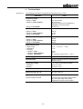
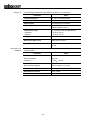
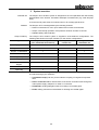
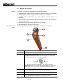
Operating Instructions Easyloc RxTx Mess- und Ortungstechnik Measuring and Locating Technologies Elektrizitätsnetze Power Networks Kommunikationsnetze Communication Networks Rohrleitungsnetze Water Networks Leitungsortung Line Locating Edition: 1 (2006/35) Reference number: 890003801 Support from SebaKMT Kabelmesstechnik GmbH This operation manual is intended to provide instructions for operation and to serve as a reference. It is designed to help you find answers and solutions to questions and problems as quickly as possible. If you should encounter a problem, please carefully read the handbook first. Refer to the table of contents and carefully read the relevant chapter. In addition, please check all connections on the devices. If the issue still cannot be resolved, please refer to the following addresses: Seba Dynatronic Hagenuk KMT Mess- und Ortungstechnik GmbH Kabelmesstechnik GmbH Dr.-Herbert-Iann-Str. 6 D - 96148 Baunach Röderaue 41 D - 01471 Radeburg / Dresden Telephone: +49 / 9544 / 68 Fax: +49 / 9544 / 22 73 0 Telephone: +49 / 35208 / 84 – 0 Fax: +49 / 35208 / 84 249 Email: [email protected] http://www.sebakmt.com SebaKMT All rights reserved. No part of this handbook may be photocopied or reproduced in any way without prior written consent from SebaKMT. We reserve the right to edit the contents of the handbook without advance notification thereof. SebaKMT assumes no liability for technical or typographical errors or mistakes in this handbook. Furthermore, SebaKMT assumes no liability for damages which directly or indirectly result from the delivery, performance or use of this material. 1-3 Terms of warranty In accordance with the following conditions, SebaKMT provides the purchaser with a warranty for all products distributed by SebaKMT. SebaKMT guarantees that SebaKMT products are free from manufacturing and material defects which could significantly reduce their value or performance at the time of delivery. This guarantee does not cover software related issues. During the warranty period SebaKMT will repair or replace defective parts with new or like new (with the same functionality and service life as new parts) parts based on its own determination. Any other warranty claims, particularly those of consequential harm caused by a defect, can not be accepted. Any parts replaced in accordance with the warranty shall remain the property of SebaKMT. The warranty from SebaKMT is valid for a period of 12 months from the date of purchase. Parts supplied by SebaKMT in fulfillment of this guarantee shall be excluded from the remaining warranty coverage period, but are guaranteed for at least 90 days under the same warranty terms. All warranty work shall be conducted by SebaKMT exclusively or through an authorised repair shop. In order to ensure that the warranty will be honored, the purchaser is responsible for notifying SebaKMT about any noticeable defects within 10 days (at the latest) of the date of purchase. This warranty shall not cover defects or damages which are the result of: misuse according to the specified usage and operating conditions, improper storage or transport, improper use or maintenance/installation performed by persons/facilities not authorised by SebaKMT. The warranty does not cover damage resulting from: normal wear and tear, forceful use or use in conjunction with third-party parts. For claims for damages resulting from the violation of rights to remedy or replacement, SebaKMT shall only be held liable in cases of gross negligence or willful wrong doing. Absolutely no liability shall be assumed for minor negligence. 1-4 Table of contents 1 Notes on safety ................................................................................................................ 1-6 2 Technical data .................................................................................................................. 2-7 3 System overview .............................................................................................................. 3-9 4 3.1 Easyloc Rx receiver ........................................................................................................ 3-10 3.2 Easyloc Tx transmitter .................................................................................................... 3-12 Using the location system............................................................................................. 4-13 4.1 Connection and initial use of the Easyloc Tx transmitter ................................................. 4-13 4.1.1 Transmitter signals and modes of operation............................................................. 4-13 4.1.2 4.1.2.1 Direct coupling on cables and pipes ..................................................................................4-14 4.1.2.2 Coupling using special connection accessories ................................................................4-16 4.1.2.3 Inductive signal coupling....................................................................................................4-17 4.1.2.4 Signal coupling in non-metallic pipes.................................................................................4-18 4.1.3 4.2 5 Options for direct and inductive signal coupling ........................................................ 4-14 Initial use of the transmitter ...................................................................................... 4-19 Locating lines with the Easyloc Rx receiver .................................................................... 4-20 4.2.1 The basics of locating lines with the receiver............................................................ 4-20 4.2.1.1 Changing the system settings............................................................................................4-20 4.2.1.2 Modes of operation for the receiver ...................................................................................4-21 4.2.1.3 Regulating the sensitivity level to match the reception signal strength..............................4-22 4.2.1.4 Handling the receiver .........................................................................................................4-23 4.2.2 General site probing ................................................................................................. 4-24 4.2.3 Determining the orientation of a line ......................................................................... 4-25 4.2.4 Determining the depth of a line................................................................................. 4-26 Maintenance ................................................................................................................... 5-30 1-5 1 Safety precautions Notes on safety This handbook contains basic instructions for the initial use and operation of the Easyloc RxTx. For this reason, it is important to ensure that the handbook is available to personnel authorised and trained to use the device at all times. Any personnel who will be using the devices should read the handbook thoroughly. The manufacturer shall not be liable for any injury or damage to personnel or property, which arise due to non-observance of the safety precautions contained in this handbook. Country specific standards and regulations should also be observed! Working with products from SebaKMT It is important to observe the general electric regulations of the particular country in which the device will be setup and used, as well as current national regulations for accident prevention and current company internal regulations (work, operating and safety regulations). The use of original accessories ensures system safety and reliable operation. The use of other parts is not permitted and shall result in termination of the warranty. Repair and maintenance Repair and maintenance work may only be performed by SebaKMT or authorised service partners. SebaKMT recommends having the system inspected and maintained at a Seba KMT service centre once a year. SebaKMT also offers its customers on-site service. Please contact your respective service centre as needed. Connections to live cables Lines without a signal Connections to live cables should be made by qualified personnel. The Easylox Rx can only locate lines which emit a signal. Therefore it is important to always exercise extreme caution when digging, even if no lines have been found. 1-6 2 Easyloc Rx Technical data The following parameters are specified for the Easyloc Rx receiver: Parameter Value Frequency ranges • Range 3: transmitter 15 kHz to 23 kHz 50 Hz / 60 Hz optionally 100 Hz (can be adjusted by SebaKMT service personnel) 32.768 kHz Sensitivity at a depth of 1 m • Range 1: radio • Range 2: power network • Range 3: transmitter >20 µA >7 mA >5 µA • Range 1: radio • Range 2: power network Dynamic response range • Range 1: radio • Range 2: power network • Range 3: transmitter 120 dB 135 dB 120 dB Depth determination Depth range Resolution Accuracy - Range 1: radio - Range 2: power network - Range 3: transmitter 0.1 m … 5 m (4 in … 16 ft) 0.1 m ±20 % ±20 % ±5 % (bis 2 m), ±20 % (2 m … 5 m) Power supply 10 x IEC R6 / AA cell / Mignon Operating time 40 hours (for intermittent use with alkaline batteries, 20 °C) Temperature range in accordance with DIN EN 60068-1 • Operation • Storage -20 °C bis +55 °C -30 °C bis +70 °C Weight 2.5 kg Dimensions (W x H x D) 99 x 660 x 252 mm Type of protection in accordance with EN 60529 Dust and water protected IP 67 from the lower edge of the receiver up to the lower edge of the battery compartment, and IP 56 for all parts 2-7 Easyloc Tx The following parameters are specified for the Easyloc Tx transmitter: Parameter Value Transmitted power 0.1 W / 0.5 W (switchable) Frequency 32.768 kHz Power supply 6 x IEC R20 / D cell / Mono Operating time 40 hours (for intermittent use with alkaline batteries, 20 °C) Temperature range in accordance with DIN EN 60068-1 • Operation • Storage -20 °C bis +55 °C -30 °C bis +70 °C Weight 1.7 kg Dimensions (W x H x D) 260 x 255 x 140 mm Type of protection in accordance with EN 60529 IP 56 Limit values and standards The following limit values and standards are applicable for the Easyloc RxTx location system: Parameter Value Sinusoidal vibrations in accordance with DIN EN 60068–2–6 Peak acceleration Frequency 20 m/s² 10 Hz 150 Hz Free fall in accordance with DIN 60068-2-32 Max. height (packaged) 80 cm (weight up to 10 kg) Relative humidity max. 93 % at 30 °C Atmospheric pressure max. 4 kPa Protection class III 2-8 3 Intended use System overview The Easyloc RxTx location system is designed for the uncomplicated and user-friendly determination of the location, orientation and depth of metallic lines (e.g. cable and pipe lines). It can be used to probe areas for unknown lines or for locating specific lines. Features The Easyloc RxTx is distinguished by the following features: • Robust construction for use in poor weather and in harsh environments • Simple, user-friendly operation concept with a minimum number of controls • Reliable battery status indicator Scope of delivery The Easyloc RxTx location system is supplied in three different configurations. The following table shows the scope of delivery for the various configurations: Easyloc RxTx system (incl. transmitter and receiver) Easyloc Rx receiver set Easyloc Tx transmitter set Easyloc Rx receiver 1 1 - Easyloc Tx transmitter 1 - 1 Measurement cable (2 m) 2 - 2 Alligator clip 2 - 2 Earthing spike 1 IEC R6 / AA cell / Mignon 10 10 - IEC R20 / D cell / Mono 6 - 6 Nylon bag 1 - - Configuration Equipment Accessories 1 SebaKMT offers a wide range of accessories for the Easyloc RxTx system which can be ordered through your distributor: • Transmitter clamp (100 mm) for the inductive coupling of a signal into exposed lines • House connection set for transmission of the house connection lines through the mains power supply, telephone or cable TV connection • FlexiSonde, emitting fibreglass cable for locating non-metallic pipes • Probe, battery powered mini-transmitter for locating non-metallic pipes 3-9 3.1 Features Easyloc Rx receiver The Easyloc Rx receiver is distinguished by the following features: • 2 passive signal modes areas for locating lines without the Easyloc Tx transmitter • 1 active signal mode for locating lines with the Easyloc Tx transmitter • Automatic depth determination when used together with the Easyloc Tx transmitter • Semi-automatic depth estimation when used without the Easyloc Tx transmitter in 2 passive signal modes • Sensitivity level can be adjusted automatically or manually • Lighted display for use in dim environments Components of the receiver The following illustration shows the components of the Easyloc Rx receiver: 1 2 3 4 5 Component Description 1 Control panel with display (see page 3-11) 2 Speaker with volume control The speaker plays back various acoustic signals (e.g. beeps with modulating pitch relative to the signal strength). Quieter Louder When the receiver is switched on, the volume is set at a standard level. The receiver will only start with the volume at a different level if the volume has been manually increased before switching off the receiver. 3 Headphone jack To connect headphones with a 3.5 mm plug connector. 4 Battery compartment 5 Floor cap This replaceable floor cap serves to protect the housing. 3-10 Display and controls The following illustration shows the control panel and display for the Easyloc Rx: 1 2 3 5 6 4 Control element 1 Description Light sensor Light sensitive photo cells to automatically regulate the display lighting. The display lighting can be manually activated for one minute by briefly covering the light sensor. 2 On/Off switch By quickly pressing this button the Easyloc Rx can be switched on or off. The Easyloc Rx will switch off automatically if no functions are carried out within 7 minutes of being switched on. 3 Display Provides a visual indication of reception strength, line depth, mode of operation, battery status and menu items. 4 Button 1 Depending on the status of the system, this button is used to: • • 5 Button 2 Depending on the status of the system, this button is used to: • • 6 Start measuring depth Manually decrease reception sensitivity Adjust reception sensitivity Start measuring depth Button 3 Depending on the status of the system, this button is used to: • • Select the mode of operation Manually increase reception sensitivity 3-11 3.2 Features Easyloc Tx transmitter The Easyloc Tx transmitter is distinguished by the following features: • Inductive coupling of the 33 kHz signal using the integrated antenna or transmitter clamp • Direct (galvanic) coupling of the 33 kHz signal using connected equipment (such as the measurement cable and power socket adapter) • Two-step (0.1 W / 0.5 W) adjustable transmission power • Selectable signal output – continuous or pulsed Transmitter control panel The following illustration shows the control panel and display for the Easyloc Tx: 4 1 5 2 3 6 Control element Description 1 Battery status indicator When the battery status LED blinks in red, the batteries need to be replaced. 2 On/Off switch By quickly pressing this button the Easyloc Tx can be switched on or off. All appropriate LED’s blink when the Easyloc Tx is on, depending on operating function. 3 “Signal type” button This button is used to switch between continuous and pulsed signal output. 4 Jacks for connecting accessories These jacks are used to create a direct galvanic connection with the target line or to create a connection using a special connection set (e.g. EasyClamp transmitter clamp or house connection set). 5 “Mode” button This button is used to switch between inductive and direct signal coupling (galvanically or via transmitter clamp). 6 “Signal strength” button This button is used to select one of two signal strength levels (0.1 W or 0.5 W). 3-12 4 Using the location system 4.1 Connection and initial use of the Easyloc Tx transmitter 4.1.1 Transmitter signals and modes of operation Signal characteristics The type and strength of the output signal can be configured by the user as follows to meet the specific requirements of either the line to be located or the site to be surveyed: Symbol Signal type Pulsed signal As it is more easily distinguished from other signals, the pulsed signal is helpful for locating when there is interference within the frequency range of the transmitter. This also helps to conserve the batteries. Depth measurements cannot be made using a pulsating signal! Continuous signal This signal type has to be activated before a taking a depth measurement. Signal strength Low output signal strength (0.1 W) Low signal strength conserves the batteries. High output signal strength (0.5 W) Mode of operation The Easyloc Tx can be used in the following modes: Symbol Tx Mode of operation Induction In this mode of operation the transmitter's signal is emitted through the integrated antenna and is thereby inductively coupled with any metallic lines located within a certain radius. Direct connection In this mode of operation the signal is directly coupled with a metallic line via the measurement cable which is connected to the jacks on the front panel of the transmitter. Transmitter clamps, alligator clips or power socket adapters (for example) may be used to connect the measurement cable to the lines. 4-13 4.1.2 Options for direct and inductive signal coupling 4.1.2.1 Direct coupling on cables and pipes Introduction Direct galvanic coupling is practical for cables which are easily accessible and free of current. The method of connection is dependent upon the position and nature of the lines (e.g. insulation, cable conduit, accessibility of the cable ends). Direct coupling presents a reliable option for selective cable location, as the signal can be coupled onto a specific cable with virtually no loss. The following illustration shows an example of direct coupling: If the lines being located are energised, the following five safety precautions should be taken before connecting the transmitter: WARNUNG Five safety precautions 1. Disconnect power 2. Secure against reconnection 3. Check for presence of current 4. Make earth connection and short circuit 5. Cover or block access to adjacent components which are energised If disconnection is not possible, use the transmitter clamp method (see section 4.1.2.2 Coupling using special connection accessories). 4-14 Principles of direct coupling The following table explains various basic principles of direct galvanic coupling: Application Single-wire lines or pipes (with or without insulation against earthing) The distance between the earth spike and the ends of the connected lines should be as great as possible. There is a danger of the return current flowing through the earth into adjacent lines, which could result in their path being followed. Single-wire cable with metallic screen and earthing insulation Short circuit between internal conductor and screen at the end of the cable with earthing at the beginning and end of the cable as well. If the earth connections made are unfavourable, the current in the internal conductor and the return current in the screen will cancel each other out. Under certain circumstances this can prevent the cable from being detected. Alternatively, a connection without an earth connection can also be made. Multiple-wire cable (internal conductor connected or disconnected) with metallic screen and earthing insulation Same application as in example 1. Metallic conduit (with or without insulation against earthing) The earth spike and the conduit should be spaced as far apart as possible. Under certain circumstances, optimum positioning of the earth spike may require several attempts. If a return wire is available The spacing of the return wire should correspond to at least 10 times the depth of the line being located. Pair of wires (with or without screen) with short circuit at the end of the cable For twisted pairs of wires (with a length of lay of the twist greater or equal to the laying depth), the orientation of the cable can be easily determined. Principle of coupling 1 2 3 4 5 6 Adjacent lines which are horizontal to each other Minimum of the reception signal Lines situated on top of each other vertically Maximum of the reception signal 4-15 4.1.2.2 Coupling using special connection accessories Coupling via adapter cable The signal from the transmitter can be directly coupled into plug sockets, antenna connections and telephone jacks with the aid of a suitable adapter cable. In doing so, it is not necessary to disconnect the lines. SebaKMT offers a ready made house connection set for this type of coupling (also see section 3 System overview, page 3-9). Coupling via transmitter clamp The transmitter signal can be coupled onto easily accessible cables with the aid of a transmitter clamp. In doing so, it is not necessary to disconnect the cables. By ensuring that the transmitter clamp is completely closed around the cable, only a small leakage field will be generated. This can significantly reduce the unwanted coupling of the signal onto neighbouring lines. Ideally the cables will be grounded at both ends; but even if they are not grounded at one end, selecting high power transmitter output will assist easy location. 4-16 4.1.2.3 Inductive signal coupling Inductive signal coupling For lines which are not easily accessible, the signal from the transmitter has to be inductively coupled via the integrated antenna. The inductive coupling of the signal is highly recommended if unknown lines are to be located (e.g. at a construction site). To determine the orientation of a specific line, the transmitter has to be positioned directly above the presumed line as shown in the following illustration. In doing so, the best signal coupling is achieved when the handle of the transmitter housing is aligned with the presumed lay of the line. When locating lines using inductive signal coupling, the following guidelines should be observed: • As the signal can be coupled onto other conductors when using inductive coupling, direct coupling of the transmitter is always preferable when locating lines selectively. Inductive signal coupling should only be opted for in cases where the line being located is not easily accessible (see section 4.1.2.1 Direct coupling on cables and pipes and section 4.1.2.2 Coupling using special connection accessories). • While taking measurements, make sure that a distance of at least 15 m is always maintained between the receiver and transmitter in order to prevent the coupling of the transmitter's signal through the air. • When searching for unknown lines at a site, the position of the transmitter has to be changed at least once by one metre and 90°. • It is also a good idea to position the transmitter at visible cable ends such as at distribution boxes or light poles. 4-17 4.1.2.4 Signal coupling in non-metallic pipes Signal coupling in nonmetallic pipes With the aid of the FlexiSonde or a sonde, the transmitter's signal can be transmitted through non-metallic pipes. To do this, the sonde has to be pushed into the pipe using a flexible cable. Both the FlexiSonde and the sonde are available as accessories for the Easyloc RxTx location system (see section System overview, page 3-9). When locating non-metallic pipes, the following guidelines should be observed: • Practice locating the sonde or Flexitracer head before pushing it into the drain or duct. • Strongest signal will be detected when the receiver is above and perpendicular to the sonde (as shown in the picture). 4-18 4.1.3 Initial use of the transmitter How to proceed Follow the steps listed below in order to prepare the transmitter to search for lines in conjunction with the receiver: Step Action 1 Connect the transmitter to the line to be located using the most suitable method, or place the transmitter on the site to be searched (see section 4.1.2 Options for direct and inductive signal coupling). 2 Press 3 Select the desired output signal using the P and M buttons (see section 4.1 Connection and initial use of the Easyloc Tx transmitter, page 4-13). to switch on the transmitter. A green LED indicates that the respective setting is active. 4 Select the desired mode of operation using the C button (see section 4.1 Connection and initial use of the Easyloc Tx transmitter, page 4-13). Result: In Direct mode, an LED next to the how good the connection is to the connected line: symbol indicates • Green blinking: good (low-resistance) connection • Alternating red and green: sufficient connection • Red blinking: poor/no (high-resistance) connection 5 As described in chapter 4.2 Locating lines with the Easyloc Rx receiver use the Easyloc Rx to locate metallic conductors. 4-19 4.2 Locating lines with the Easyloc Rx receiver 4.2.1 The basics of locating lines with the receiver 4.2.1.1 Changing the system settings How to proceed To reach the system menu in the receiver, proceed as follows: Step Action 1 Press and hold the 2 Briefly press the button while continuing to hold down the 1 button until an audible signal is heard. The following image is display: 3 Now one of the following depth measurement processes may be selected by pressing the 1 button: 1 button. Select this symbol if depth measurements will be made with the aid of a sonde. Select this symbol if normal depth measurements (without sonde) will be made. Now a unit of length used by the system may be selected by pressing the 3 button: Foot (ft) will be used as the unit for length. Metre (m) will be used as the unit for length. 4 Press the 2 button to save the settings. The changes will remain in effect even after the receiver is switched off and back on again. 4-20 4.2.1.2 Modes of operation for the receiver Basics of passive line location If a Easyloc Tx transmitter is not available, a site can also be probed by means of passive line location. The Easyloc Rx receiver is capable of detecting radio signals in the frequency range between 15 kHz to 23 kHz as well as power signals in the frequency range between 50 / 60 Hz. The following pictures illustrate how each of the signals couple onto conductors buried in the ground: Modes of operation for the transmitter The two options explained above for passive location together with the option of active location with the Easyloc Tx transmitter result in the following three modes of operation: Symbol Mode of operation RADIO For locating cables which are carrying VLF reradiated radio signals. POWER GRID For locating mains power supply cables, through which current with a grid frequency is flowing. TRANSMITTER For locating cables or pipes, onto which the signal from the Easyloc Tx transmitter will be coupled. 4-21 4.2.1.3 Regulating the sensitivity level to match the reception signal strength Display of reception signal strength and sensitivity Reception signal strength and sensitivity are shown in the following segments of the display: 2 1 Segment 1 Mode of operation Reception signal display bargraph The strength of the reception signal is represented by this bargraph scale. These are relative values which are based on the sensitivity level set in the receiver. The triangles ( ) above and below the scale are a visual marker for maximum values. They move towards the right as long as the signal strength increases and continue in this direction until it either levels off or decreases. The maximum marker remains in this position for 3 seconds and thus provides the user with a helpful visual aid for determining the maximum signal strength. 2 Sensitivity display (gain level in %) The sensitivity level set in the receiver (which coincides with the total spectrum which the receiver is capable of processing) is represented by this scale. The higher the level of sensitivity is set, the more capable the receiver is of detecting weaker signals. The numeric display above the bars shows the utilisation factor as a percent. Regulating the sensitivity level Should the scale for reception signal strength bargraph provide virtually no indication, or the display is completely utilised, either a manual or automatic adjustment of the sensitivity level has to be made. To start an automatic sensitivity level adjustment, the 2 button has to be pressed once. The sensitivity level of the receiver will be automatically adjusted so that the strength of the signal currently being received will be optimally displayed (fill half of the scale). To start a manual sensitivity level adjustment, the 2 button has to be pressed twice in rapid succession. The following indicator will appear in the display: Now the sensitivity of the receiver can be decreased by one percent by pressing the 1 button, or increased by one percent by pressing the 3 button. This process can be accelerated by holding down the respective button. To exit the manual sensitivity level adjustment menu, the 2 button has to be pressed twice in rapid succession. By pressing the button only once, the depth measurement process will begin (see section 4.2.4 Determining the depth of a line). 4-22 4.2.1.4 Handling the receiver and locating the line Basics for handling the receiver In order to be able to determine the position and orientation of a metallic conductor, the following rules should be internalised and applied when locating lines. As shown in the following illustration, the receiver should always be held in front of the body in an upright position and as close to the ground as possible. When the transmitter is brought directly over a metallic conductor, the maximum signal strength will be measured. If the receiver is moved away from the conductor towards the side and is not rotated while doing so, the signal will drop off proportionately. The alignment of the receiver in relation to the orientation of the conductor (the antenna being the starting point of alignment) has the following effects on the reception signal strength: • Receiver in line with the conductor • Receiver perpendicular to the conductor 4-23 maximum signal strength minimum signal strength 4.2.2 General site surveying Requirement A general site probing urgently needs to be conducted and there is inaccurate or no information available as to the location and orientation of metallic conductors on a site planned for construction (e.g. excavation work). Basics of site surveying When a site is to be searched for unknown conductors, a systematic approach should be taken. The following picture illustrates how to proceed: Carry out a passive survey in POWER GRID and RADIO modes using a grid search pattern to cover the site and locate conductors in all directions. If the site will be surveyed with the aid of the Easyloc Tx transmitter used on induction, the position of the transmitter should be changed by at least one metre and 90° after the first sweep of the site and the site should be probed again in the same manner. The minimum spacing of 15 m between the transmitter and receiver must always be maintained. How to proceed Follow the steps below when probing a site for unknown metallic conductors: Step Action 1 If the site will be searched with the aid of the Easyloc Tx transmitter, the transmitter needs to be configured as described in section 4.1.3 Initial use of the transmitter before proceeding. 2 Press 3 Select the desired mode of operation (see section 4.2.1.2 Modes of operation for the receiver) by pressing the 3 button. to switch on the receiver. The symbol for the currently selected mode of operation is shown in the lower right-hand corner of the display. 4 Pace off the site as previously described and make a grid search of the site. Adjust the sensitivity of the receiver as needed if the signal level is too strong / weak (see section 4.2.1.3 Regulating the sensitivity level to match the reception signal strength). 5 When a conductor is located, pinpoint the strongest signal (see section 4-24 4.2.3 Determining the direction of a line How to proceed Follow the steps below to determine the orientation of a metallic conductor: Step Action 1 If the direction of the conductor will be determined with the aid of the Easyloc Tx transmitter, couple the transmitter's signal onto the metallic conductor in such a way that there is as little signal loss as possible (see section 4.1.2 Options for direct and inductive signal coupling) and switch on the transmitter (see section 4.1.3 Initial use of the transmitter). 2 Press to switch on the receiver. Select the desired mode of operation (see section 4.2.1.2 Modes of operation for the receiver) by pressing the 3 button. The symbol for the currently selected mode of operation is shown in the lower right-hand corner of the display. 3 4 Hold the receiver perpendicular to the position of a known metallic conductor, e.g. above a location which was marked during the probing of the site (see section 4.2.2 General site surveying). 5 Rotate the receiver (through its own axis) over this location until the maximum signal strength is indicated (see section 4.2.1.4 Handling the receiver). Result: The receiver is in line with the conductor when it is positioned where the signal is strongest, which is prerequisite for determining the direction of the line. 6 To determine the path over an extended distance, proceed by moving forward while maintaining the maximum signal strength. If the signal becomes weaker, check that the conductor has not changed direction or become deeper, move and/or rotate the receiver to the left and right until the maximum signal strength is detected again. The path of the metallic conductor should always be followed until it exits the site being searched, and its path should be clearly marked along the way with paint/chalk or marker flags. Adjust the sensitivity of the receiver as needed if the signal level is too strong / weak (see section 4.2.1.3 Regulating the sensitivity level to match the reception signal strength). It is advisable to manually adjust the sensitivity level. 4-25 4.2.4 Determining the depth of a line Preconditions for automatic depth measurement The Easyloc Rx receiver has an automatic pushbutton depth measurement feature. One precondition is that a clear signal from the Easyloc Tx transmitter is coupled onto the conductor to be measured. For this procedure, the transmitter's signal has to be continuous (not pulsed) (see section 4.1.1 Transmitter signals and modes of operation). In addition to this precondition, automatic depth measurement will only function when the mode of operation is set to TRANSMITTER. It will not function if set to POWER GRID or RADIO. If these preconditions are not met, a rough estimate of the depth may be made using the manual method. Measuring depth with the aid of a sonde WARNUNG How to proceed If the depth of a non-metallic pipe needs to be determined, the measurement has to be made with aid of a sonde or the FlexSonde (see section 4.1.2.4 Signal coupling in non-metallic pipes). In order to accommodate the transmission characteristics of a sonde, the Easyloc Rx receiver has a special depth measurement feature which has to be activated through the system settings (see section 4.2.1.1 Changing the system settings). Even after the depth has been successfully determined, all excavation work should be done with caution. This is particularly important if a rough estimate of the depth was made, as this can result in even greater deviations. Follow the steps below to determine the depth of a metallic conductor: Step Action 1 If the depth of the conductor will be determined with the aid of the Easyloc Tx transmitter, couple the transmitter's signal onto the metallic conductor in such a way that there is as little signal loss as possible (see section 4.1.2 Options for direct and inductive signal coupling) and switch on the transmitter (see section 4.1.3 Initial use of the transmitter). Do not forget to set the transmitter to continuous signal, not a pulsed signal when measuring depth. 2 3 4 Press to switch on the receiver. Select the desired mode of operation (see section 4.2.1.2 Modes of operation for the receiver) by pressing the 3 button. The symbol for the currently selected mode of operation is shown in the lower right-hand corner of the display. With a steady grip, hold the receiver perpendicular to the position of a known metallic conductor, e.g. above a location which was marked during the site survey. The signal strength bargraph should show zero (see section 4.2.2 General site surveying). In doing so, the tip of the receiver should touch the ground. 5 Rotate the receiver (through its own axis) over this location until the maximum signal strength is indicated (see section 4.2.1.4 Handling the 4-26 Step 6 Action Press the 1 button to begin measuring the depth. For automatic depth measurement (while working in TRANSMITTER For making a rough estimate of the depth (while working in RADIO mode) or POWER GRID mode) ... the measured depth will be shown in the display: ... the following symbol will appear in the display: The following steps can be skipped. The measurement has to be continued from step 7. 7 Move to one side until the following symbol appears in the display: 8 Mark this spot, then move in the opposite direction to the other side of the line until the symbol appears in the display again. 9 Mark this spot as well, then measure the distance between the two spots. Result: Half the distance between the two spots corresponds approximately to the depth of the line. 4-27 Indications and error messages During the depth measuring process, the following symbols are used to notify the user about certain characteristics and errors: Symbol Meaning For of one of the following reasons, the depth could not be measured: • The signal received was too weak or too irregular. • The receiver was not held steady enough during the measuring process. • The receiver was not positioned directly above the line at the beginning of the process. The depth of the metallic conductor amounts to more than 5 m (16 ft). The depth of the metallic conductor amounts to less than 30 cm (1 ft). Such conductors must be specially marked in order to prevent damage during construction. The receiver was moved too far to the left or right while making a rough estimate. Move in the opposite direction until the following symbol appears: Proceed as described in step 8 on the previous page. 4-28 4.2.5 Masking-Out Lines Masking-out lines Under certain circumstances lines at lower depths can 'hide' deeper, adjacent lines, thus making it more difficult to locate them. In such cases, the transmission characteristics of the Easyloc Tx transmitter can be fully utilised and the lines which have already been located can be masked out. Line with weaker inductive coupling How to proceed Line with good inductive coupling Follow the steps listed below in order to locate lines by masking-out adjacent lines: Step Action 1 Use the Easyloc Rx and Easyloc Tx to locate and pinpoint a buried line (see section 4.2.2 General site surveying). 2 With the Easyloc Rx rested on the ground straight above the located line, ask a colleague to place the Easyloc Tx on its back (see picture) nearby the line path (at least 15 m away from the receiver). 3 Slide the Easyloc Tx across the line until the signal strength bargraph is lowest, indicating that the transmitter is directly above the line which, thus, is masked-out. Note that adjacent lines may not be parallel with the first cable route, so sweep the receiver around in a circle about 10 m - 15 m radius from the transmitter, with the handle pointing towards the transmitter. Any metallic lines within 2.5 m of the transmitter will be coupled with the transmitted signal 4 Pinpoint and determine the direction of any buried lines (see section 4.2.1.4 Handling the receiver). 4-29 5 Changing the batteries in the receiver Maintenance The status of the receiver's batteries is checked upon start-up and indicated in the display. The system regularly checks the battery strength as well. If battery capacity falls below 10 % of the threshold value, an audible warning signal is given and the current status of the batteries is shown in the upper part of the display. In order to replace the ten 1.5 V mignon (AA) batteries, the battery housing must be removed as described in the following illustrations: 2 1 5-30 Changing the batteries in the transmitter The batteries in the transmitter have to be replaced as soon as the red LED battery indicator starts to blink. Should this occur while the user is busy locating a line with the receiver, he/she will be informed of the weak batteries via the reception signal: Type of signal Normal signal Signal when batteries are weak In order to change the six 1.5 V mono (D cell) batteries, both screws on the back of the transmitter must be (e.g. with the aid of a coin) turned through ¼ turn (1) and the battery tray must be pulled (2). Please note that all the battereies are fitted in the same direction. 2 1 Changing the floor cap on the receiver The plastic floor cap, which prevents the tip of the receiver from being damaged, can be easily replaced with the aid of a pointed object (e.g. screw driver). Replacements can be ordered through the SEBA KMT sales team. 5-31 Entsorgung des Gerätes Nur für Erwerber innerhalb der EU: Befindet sich auf dem Typenschild des von ihnen erworbenen Gerätes eine WEEE-Reg.-Nr. (z.B. WEEEReg.-Nr. DE 24650880), so handelt es sich bei dem von Ihnen erworbenen Gerät um ein B2B Gerät (ausschließlich zur gewerblichen Nutzung) entsprechend Richtlinie 2002/96/EG (WEEE) bzw. deutschen Elektro- und Elektronikgerätegesetz – ElektroG und ist durch den Erwerber entsprechend dieser Richtlinie zu behandeln. The buyer is prohibited from selling it to a private user. Für die durch Veräußerung des Gerätes an private Endverbraucher durch den Erwerber evtl. entstehenden Kosten, zu Lasten „Seba Dynatronic“ oder „Hagenuk KMT“ durch den Gesetzgeber, ist der Erwerber schadensersatzpflichtig. Zur Entsorgung hat der Erwerber, soweit es keine anderslautende Vereinbarung zwischen ihm und dem Hersteller gibt, das Produkt an den Hersteller (Erst-Inverkehrbringer) zurück zu senden, damit dieser es dem gesetzlich relevanten Wertstoff Recycling System des jeweiligen EULandes zuführen kann. Wenn Unsicherheiten bzgl. der Entsorgung bestehen, nehmen Sie bitte Kontakt mit dem Hersteller auf. Disposal of the equipment Only for buyers within the EU: If there is a WEEE Reg. No. (e.g., WEEE Reg. No. DE 24650880) on the type plate of the equipment you have bought, then the equipment is a B2B appliance (exclusively for commercial use) according to European guidelines 2002/96/EC (WEEE) or to the German electronic and electrical equipment law (ElektroG), and it must be treated by the buyer in accordance with these guidelines. The buyer is prohibited from selling it to a private user. Damages may be claimed from the buyer for any costs placed on “Seba Dynatronic” or “Hagenuk KMT” by the legislator, resulting from the sale of the equipment to a private person. To dispose of the equipment, once no separate agreement has been reached between the buyer and the manufacturer, the buyer must return the equipment to the manufacturer (first to put it into circulation), so that they can introduce it to the legally relevant recycling system of the EU country concerned. If unsure about the disposal of the equipment, please contact the manufacturer. Elimination de l’appareil Uniquement pour acquéreurs de l’Union Européenne : si un numéro d’enregistrement (p. ex. DE 24650880) se trouve sur la plaque signalétique de l’appareil dont vous avez fait l’acquisition, cet appareil est un appareil de type B2B (réservé exclusivement à un usage commercial) conformément à la directive 2002/96/EG (WEEE) ou à la loi allemande sur les équipements électriques et électroniques (ElektroG) et doit être utilisé par son acquéreur dans le respect de cette réglementation. La cession à un utilisateur privé par l’acquéreur est interdite. L’acquéreur est tenu de réparer le dommage pour tous coûts éventuels résultant de la cession de l'appareil à un utilisateur privé par l’acquéreur et imputables à « Seba Dynatronic » ou « Hagenuk KMT » de par la législation. Pour que le produit soit éliminé, sauf accord entre acquéreur et fabricant stipulant autrement, l’acquéreur devra renvoyer le produit à son fabricant (responsable de la première mise en circulation) afin que ce dernier puisse le remettre au système approprié de retraitement de matériaux recyclables du pays de l’Union Europénne concerné. En cas d’incertitudes concernant l’élimination du produit, veuillez contacter le fabricant. Eliminar el aparato Sólo para compradores dentro de la UE: Si un número de registro RAEE en la placa de características del aparato (por ejemplo, número de registro RAEE DE 24650880), se trata de un aparato B2B (destinado exclusivamente a uso comercial) de conformidad con a la directiva 2002/96/CE (RAEE) o a la ley alemana relativa a aparatos eléctricos y electrónicos (ElektroG), y el comprador sólo lo puede usar de conformidad a esta directiva. Queda prohibida la venta por parte del comprador a un consumidor final particular. En caso de que el comprador venda el aparato a un consumidor final particular, el primero estará obligado a pagar una indemnización en concepto de los costes establecidos por ley que puedan surgir para “Seba Dynatronic” o “Hagenuk KMT”. Cuando el comprador desee desechar el aparato, y siempre que no se haya acordado otra cosa entre éste y el fabricante, lo deberá enviar al fabricante (distribuidor originario) para que este último lo integre en el sistema de reciclaje dispuesto por ley en el país en cuestión de la UE. Si tiene dudas respecto al modo de desechar el aparato, póngase en contacto con el fabricante. Smaltimento dell’apparecchio Solo per acquirenti all’interno dell’UE: Se sulla targhetta dell’apparecchio acquistato da voi è applicato un n. di reg. RAEE (ad es. n. reg. RAEE DE 24650880), l’apparecchio da voi acquistato è un apparecchio del tipo B2B (adatto esclusivamente per scopi commerciali) conforme alla direttiva 2002/96/CE (RAEE) o alla legge tedesca sullo smaltimento dei rifiuti di apparecchiature elettriche ed elettroniche (ElektroG) e dopo l’acquisto va trattato in conformità a questa direttiva. All’acquirente è vietata la cessione del presente apparecchio ad utenti privati finali. In caso di cessione dell’apparecchio da parte dell’acquirente a clienti privati finali, gli eventuali costi risultanti a carico di “Seba Dynatronic” o “Hagenuk KMT”, determinati dal legislatore, andranno a carico dell’acquirente stesso come risarcimento danni. L’acquirente deve rispedire il prodotto al produttore (primo distributore) per lo smaltimento, se non esistono accordi diversi fra lui e il produttore, affinché questo possa provvedere a smaltirlo secondo il sistema di riciclaggio previsto dalla legge vigente nei singoli paesi UE. Qualora emergano dubbi relativi allo smaltimento, non esitate a contattare il produttore. 5-32