1
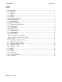
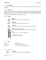
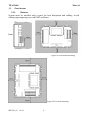
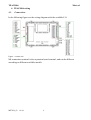
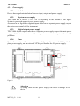
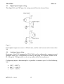
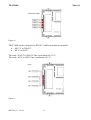
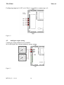
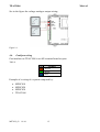
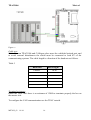
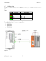
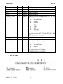
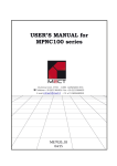
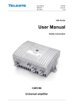
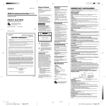
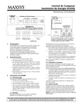
TPAC1006 Mect srl USER’S MANUAL for TPAC1006 series ME7022_03 10/14 ME7022_03 10/14 TPAC1006 ME7022_03 10/14 Mect srl TPAC1006 Mect srl INDEX 1. Introduction.............................................................................................................. 1 1.1. Staff skill ............................................................................................................ 1 1.2. Simbols............................................................................................................... 1 1.3. Terms ................................................................................................................. 1 1.4. Security .............................................................................................................. 1 1.5. Reference manuals ............................................................................................. 2 2. System description ................................................................................................... 2 2.1. Specification....................................................................................................... 4 3. Hardware Installation............................................................................................... 5 3.1. Mechanical dimensions ...................................................................................... 5 3.2. Panel mount........................................................................................................ 8 3.2.1. Distance ........................................................................................................ 8 4. TPAC1006 wiring .................................................................................................... 9 4.1. Connections ........................................................................................................ 9 4.2. Power supply .................................................................................................... 11 4.2.1. Isolation ...................................................................................................... 11 4.2.2. System power supply ................................................................................. 11 4.2.3. Digital output power supply ....................................................................... 11 4.2.4. Fuse ............................................................................................................ 11 4.3. Digital input/output wiring .............................................................................. 12 4.4. Analogue input wiring ..................................................................................... 12 4.5. Analogue output wiring ................................................................................... 14 4.6. CanOpen wiring ............................................................................................... 15 4.7. ModBus wiring ................................................................................................ 17 5. Peripherals ............................................................................................................. 18 5.1. USB .................................................................................................................. 18 5.2. Ethernet ............................................................................................................ 18 6. PLC and HMI ........................................................................................................ 18 6.1. System variables .............................................................................................. 18 7. How to order .......................................................................................................... 19 ME7022_03 10/14 TPAC1006 Mect srl 1. Introduction To grant a fast setup of the device please follow carefully the information in this manual. 1.1. Staff skill Products described in this manual are devoted to PLC programmers or automation experts only. MECT S.r.l. declines any responsibility about malfunctioning or damage caused by incorrect use of MECT devices, due to noncompliance to this manual information. MECT S.r.l has an help desk. 1.2. Simbols Danger Follow this advice to avoid people injury. Warning Follow this advice to protect the device. Caution Follow this advice to have a more effective performance. ESD ( Electrostatic discharge) Danger: possibly damage due to Electrostatic discharge. Note Step to follow for a correct installation. Additional information 1.3. Terms PLC: Terminals: System: 1.4. TPAC1006 MPNC020; MPNC030 PLC (TPAC1006) with terminals Security Attention Switch off devices before connecting them. ME7022_03 10/14 1 TPAC1006 Mect srl ESD (Electrostatic discharge) Modules have electronic components that can be damaged by. electrostatic discharge. Be sure to be connected to ground when handle the devices. The instrument has no power switch and no internal fuse, but it powers on immediately after connecting a correct power supply input (check the power supply value on the instrument label). Keep the power supply line as short as possible and keep it separate from other power lines. For security reasons it is necessary to have a 2 section power switch with a fuse near the instrument and easily replaceable. Avoid the presence of other power actuators in the same control panel, high humidity, excessive heat and corrosive gas. Instruments must have a power supply from security transformers or SELV transformers. 1.5. Reference manuals M7027 Qt Mect Suite-Tutorial M7028 Qt mect configurator 2. System description TPAC1006 is a device composed by a PLC and a HMI with touch-screen monitor 5,7” width and 320 x 240 pixel resolution (640x480 if HR option) with 262.000 colors. TPAC1006 has digital and analogue input and output, field bus CanOpen and Modbus, and a 100Mbit/s Ethernet. The device can be used in horizontal or in vertical design with the option "V" (see following pictures). ME7022_03 10/14 2 TPAC1006 Mect srl Figure 1: Front view TPAC1006 (horizontal version) Figure 2: Front view TPAC1006 (vertical version) ME7022_03 10/14 3 TPAC1006 Mect srl 2.1. Specification TPAC1006 is based on a multiprocessor system. PLC and HMI are based on a 454MHz ARM9, I/O interface and I/O acquisition is based on a Cortex M3 processor. The 2 systems on different boards communicate over a CAN channel. Table 1 PLC Hardware characteristics PLC Processor RAM FLASH Non volatile variables Real Time Clock Screen Screen (option HR) Touch screen Ethernet USB I/O hardware characteristics Processor PLC software characteristics OS PLC Graphics CAN ModBus Storage memory ME7022_03 10/14 ARM926JE 454MHz 128MB 128MB On FLASH memory Yes with rechargeable battery TFT 320 x 240 pixel 262k colors TFT 640 x 480 pixel 262k colors Resistive 4 wires 10Mbit/s - 100Mbit/s self recognition Host 2.0 Cortex-M3 72MHz LINUX 2.35 IEC61131-3 Based on QT library CanOpen 2.0 Modbus RTU master Possibility of history storage 4 TPAC1006 Mect srl 3. Hardware Installation In the following figures see the TPAC1006 dimensions. 3.1. Mechanical dimensions Side view Rear view Figure 3 Figure 4 Side view Figure 5 ME7022_03 10/14 5 TPAC1006 Technical specification Mect srl Table 2 Mechanical Material Dimensions W x L x H Polycarbonate, Polyamide 6.6 195 mm x 145 mm x 60.5 mm Mounting plate 139mm x 189mm Installation Panel installation Environmental conditions Operative temperature 0 °C ... 55 °C Storage Temperature -20 °C ... +85 °C Relative Humidity 5 % a 95 % no condensation Electric isolation Air clearance According to IEC 60664-1 Pollution 2 According to IEC 61131-2 Protection Rear protection IP 20 Front protection IP65 EMC EMC according to EN 61000-6-2 (2001) Test specification Values Class EN 61000-4-2 ESD EN 61000-4-3 electromagnetic fields EN 61000-4-4 burst EN 61000-4-5 surge 4 kV/8 kV (contact/air) 10 V/m 80 MHz ... 1 GHz Criterion 2/3 3 B A 1 kV/2 kV (data/supply) 2/3 Data: -/- (line/line) 1 kV (line/earth) 2 DC 0.5 kV (line/line) 1 supply: 0.5 kV (line/earth) 1 AC 1 kV (line/line) 2 supply: 2 kV (line/earth) 3 EN 61000-4-6 10 V/m 80 % AM (0.15 ... 80 3 RF disturbances MHz) Emissions according to EN 61000-6-4 (2001) Limit Frequency Test specification values/IQPI Range B B 79 dB (µV) ME7022_03 10/14 6 150 kHz ... 500 kHz B B A Distance TPAC1006 EN 55011 (AC supply, conducted) Mect srl 73 dB (µV) EN 55011 (radiated) 40 dB (µV/m) 47 dB (µV/m) Emissions according to EN 61000-6-3 (2001) Test specification Limit values/IQPI EN 55022 (AC supply, 66 ... 56 dB conducted) (µV) 56 dB (µV) 60 dB (µV) EN 55022 (DC supply/data, 40 ... 30 dB conducted) (µA) 30 dB (µA) EN 55022 (radiated) 30 dB (µV/m) 37 dB (µV/m) 500 kHz ... 30 MHz 30 MHz ... 230 MHzMHz ... 1 230 GHz Frequency Range 150 kHz ... 500 kHz 500 kHz ... 5 MHz 5 MHz ... 30 MHzkHz ... 500 150 kHz 500 kHz ... 30 MHz 30 MHz ... 230 MHz 230 MHz ... 1 GHz 10 m 10 m Distance 10 m 10 m Digital input 8 Input Range 0 - 24Vdc +/- 15% Digital output 12 Max current for each digital output: 500mAdc@24Vdc Analogue input Analogue output Power 4 2 PT100, TCJ, TCK,TCT, 0-10Vdc,4(0)-20mA 0-10Vdc, 4(0)-20mA 7.2 W no load Attention Install the device in a panel with no more than 55 °C. ME7022_03 10/14 7 TPAC1006 3.2. Panel mount Mect srl 3.2.1. Distance System must be installed with a space for heat dissipation and cabling. Avoid cabling superimposing to avoid EMC problems. Figure 6A: Horizontal mounting Figure 6B: Vertical mounting ME7022_03 10/14 8 TPAC1006 4. TPAC1006 wiring 4.1. Mect srl Connections In the following figure see the wiring diagram with the available I/O. Figure 7: Pinout PLC M4 connection terminal is the expansion board terminal, and can be different according to different available models. ME7022_03 10/14 9 TPAC1006 Table 3 Mect srl Analogue input N° 4 Analogue output N° 2 Input (rpm) N° 1 Digital Input/Encoder input N°8 TPAC1006 01 Input type Resolution 0.01mA 420 mA 0.005V 0V thermocouples 1°C J(0°C – 600°C), T(0°C – 400°C), K(0°C – 1200°C) PT100 r -40.0°C 0.1°C – 200.0°C PT100 E 1°C -40°C-800°C Output type Resolution 0.01mA 420 mA 0-10V 0.005V Input type Resolution rpm Max Frequency 1kHz (60000 rpm) Input type Resolution PNP Max Frequency 500Hz Output type PNP Note Input impedance 9 Input impedance 1M Cold junction compensation Note Max Impedance: 400 Min Impedance: 1K Note Note input 2 and 3 can be used as incremental encoder input Fmax 40kHz D2: A input D3: B input Note Max 500mA for each output. 2 A max total load Resolution Max Digital output N°12 Frequency 500Hz Power supply 24Vdc 15% 400mA I/O power supply 24Vdc 15% CANOpen 1 channel Max Bit rate: 1Mbit/sec Cycle time: 10msec USB A 2.0 Ethernet Bit rate: 100Mbit/sec Serial output RS485 full duplex (by hardware configuration) ME7022_03 10/14 10 TPAC1006 4.2. Power supply Mect srl 4.2.1. Isolation Device has no galvanic isolation between input, output and power supply. 4.2.2. System power supply TPAC1006 has a 24VDC (-15% +20 %) according to the scheme in the figure. System is protected against reverse power supply. As shown in the figure, the digital outputs must have a separate power supply respect the main power supply of the instrument. 4.2.3. Digital output power supply TPAC1006 digital outputs must have a separate power supply respect the main power supply of the instrument to avoid consequences on control system due to I/O problems. 4.2.4. Fuse System has no internal fuse , so is suggested the use of an external 1A fuse for the panel power supply, and an external 3A delayed fuse for the I/O power supply. Power 1A 24Vdc I/O power supply 24Vdc 3A delayed fuse Figure 8 Attention A wrong value for the power supply can cause a damage to the device. ME7022_03 10/14 11 TPAC1006 4.3. Digital input/output wiring The digital I/Os are PNP type, the wiring must follow the scheme below. Mect srl Figure 9 Each digital output can source a 500mA max, and the total current can be lower than 2A. 4.4. Analogue input wiring By means of the PLC program the TPAC1006 can be configured to connect several analogue input type. Configuration is done by the setup of a system variable in the PLC program. Configuration can be set up and modified in any moment. Configuring input as thermocouple it is possible to connect up to 4 of the following type: J (0°C – 600°C), K(0°C – 1200°C) T (0°C – 400°C) ME7022_03 10/14 12 TPAC1006 Mect srl thermocouple Figure 10 TPAC1006 can be connected to PT100. 2 different scales are possible: –40.0 °C to 200.0°C –40 °C to 800°C The scale –40.0°C to 200.0°C has a resolution of 0.1°C. The scale –40°C to 800°C has a resolution of 1°C. Figure 11 ME7022_03 10/14 13 TPAC1006 Mect srl Configuring input as 0V or 4 is possible to connect up to 4: Figure 12 4.5. Analogue output wiring 2 analogue output channels are available. See in the figure the current analogue output wiring. Figure 13 ME7022_03 10/14 14 TPAC1006 Mect srl See in the figure the voltage analogue output wiring. Figure 14 4.6. CanOpen wiring Can interface on TPAC1006 is on M1 terminal board on pins: Table 4 Pin Segnale 1 CAN H 2 CAN L 3 GND Example of a wiring of a system composed by: MPNC010 MPNC020 MPNC030 TPAC1006 ME7022_03 10/14 15 TPAC1006 Mect srl Figure 15 Cable type Cable between TPAC1006 and CANopen slave must be a shielded twisted pair, and to avoid external disturbances the shield must be connected to both 0V of the communicating systems. The cable length is a function of the baud rate as follows. Table 5 Baud rate 1 Mbit/s 800 kbit/s 500 kbit/s 250 kbit/s Bus Lenght 10 m 50 m 100 m 250 m 125 kbit/s 500 m 1000 m 50 kbit/s Terminal resistance Inside the TPAC1006 there is a resistance of 120 to terminate properly the bus on the master side. To configure the CAN communication see the TPAC tutorial. ME7022_03 10/14 16 TPAC1006 Mect srl 4.7. ModBus wiring ModBus on TPAC1006 is a 4 wire RS485 serial line, on the M2 terminal board on pins: Table 6 Pin 11 12 13 14 15 Segnale GND TX + TX RX + RX - Description Line + Tx Line - Tx Line + Rx Line - Rx Example of a wiring of a system composed by: TPLC005 MPNC020 MPNC030 TPAC1006 wire Figure 16 ME7022_03 10/14 17 TPAC1006 5. Peripherals Mect srl 5.1. USB TPAC1006 has an USB 2.0 host for: software update. data storage: datalogger. Connect USB peripherals as printers, mouse, etc. Specific connection of external peripherals are implemented on request. 5.2. Ethernet TPAC1006 has a 10/100Mbit/s ethernet port with autoconfiguration, with direct or inverse connection cable. TAPC1006, by ethernet, can be controlled by a personal computer, it is possible to control the I/O of TPAC1006 by means of a program on a PC. 6. PLC and HMI To program TPAC1006 it is necessary to develop 2 software. A PLC program written with the PLC program IDE software. A human machine interface program (HMI) written with Qt Creator. A PLC program can be written using one of the following standard IEC 61131-3 languages: Table 7 FBD LD SFC ST IL (AWL) Functional Block Diagram Ladder Sequential Function Chart Structured Text Instruction List Graphic Graphic Graphic Text Text Contact scheme Ladder scheme State diagram Pascal-like language Assembler-like language The 2 programming environment (PLC and HMI) are for windows OS. 6.1. System variables Here some system variables available for PLC program. Table 8 Variable name DOUT_00_07 DOUT_08_15 ME7022_03 10/14 Dim Type 8 BYTE 8 BYTE Description Digital Output 00 - 07 Digital Output 08 –15 (out 13 to 15 are not implemented) 18 TPAC1006 IN_00_07 AIN1 AIN2 AIN3 AIN4 CONFIG_AIN Mect srl 1 2 2 2 2 2 BOOL WORD WORD WORD WORD WORD AOUT1 AOUT2 CONFIG_AOUT 2 2 2 WORD WORD WORD Digital Input 00- 07 Analogue Input Analogue Input Analogue Input Analogue Input Analogue input configuration (4 bit for channel): 0 not configured 1 current 2 voltage 3 TCJ 4 TCK 5 TCT 6 PT100R 7 PT100E ex: ch1 current; ch2 TCJ; ch3 PT100E; ch4 TCT CONFIG_AIN:=16#5731 Analogue output 1 Analogue output 2 Analogue output configuration (4 bit for channel): 0 not configured 1 current 2 voltage ex: ch1 current; ch2 voltage; CONFIG_AOUT:=16#0021 7. How to order ME7022_03 10/14 19