1
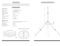
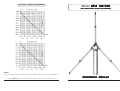
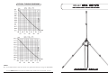
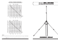
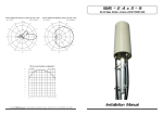
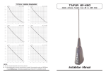
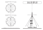
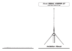
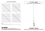
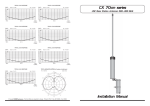
TYPICAL TUNING DIAGRAMS
Model GPA 27-45
Ground Plane Antenna 27-45 MHz
NOTE:
It is recommended to use the curves as a guide and fine-tune using an SWR-Meter.
B Copyright SIRIO antenne - Technical Data are subjected to change - Printed in ITALY - Rev. 31/07/1997 - Cod. ID174
Installation Manual
DESCRIPTION
MOUNTING INSTRUCTIONS
1/4 λ Ground Plane antenna for base station service working on 27-45 MHz by means of the
tuning diagram enclosed. It is entirely made of non-corrosive aluminium and assembled on a
strong die-cast base which allows an easy and safe installation assuring very good performances.
SPECIFICATIONS
Electrical Data
Type
Frequency Range
Impedance
Radiation
Polarization
Gain
Bandwidth at V.S.W.R. 2:1
V.S.W.R. at f. res.
Max Power
Feed System / Position
Connection
:
:
:
:
:
:
:
:
:
:
:
1/4 λ Ground Plane
27-45 MHz tunable by diagram
50 Ω Unbalanced
Omnidirectional
Vertical
0 dBd - 2.14 dBi
2.5 MHz at 27 MHz
≤ 1.2 : 1
1000 Watts
Direct / Center
UHF Female
:
:
:
:
:
:
:
Aluminium, Chromed Brass, Nylon, Stainless Steel
126 N at 150 Km/h / 130 Km/h
0.11 m2
4730 mm
1250 gr
2680 mm
∅ 35-40 mm
Mechanical Data
Materials
Wind Load / Resistance
Wind Surface
Height (approx.)
Weight (approx.)
Radial Length (approx)
Mounting Mast
TYPICAL S.W.R. RESPONSE
S.W.R.
3.0
2.8
2.6
2.4
2.2
2.0
1.8
1.6
1.4
1.2
1.0
25.4
ID174
27
28.6
f. (MHz)
TYPICAL TUNING DIAGRAMS
Model GPA 40-70
VHF Ground Plane Antenna 40-70 MHz
NOTE:
It is recommended to use the curves as a guide and fine-tune using an SWR-Meter.
B Copyright SIRIO antenne - Technical Data are subjected to change - Printed in ITALY - Rev. 02/07/1998 - Cod. ID175
Installation Manual
DESCRIPTION
1/4 λ Ground Plane antenna for base station service working on 40-70 MHz by means of the
tuning diagram enclosed. It is entirely made of non-corrosive aluminium and assembled on a
strong die-cast base which allows an easy and safe installation assuring very good performances.
SPECIFICATIONS
Electrical Data
Type
Frequency Range
Impedance
Radiation (H-plane)
Radiation (E-plane)
Radiation angle deg.
Polarization
Gain
Bandwidth at V.S.W.R. 2:1
V.S.W.R. at res. freq.
Max Power
Feed System / Position
Connection
:
:
:
:
:
:
:
:
:
:
:
:
:
1/4 λ Ground Plane
40-70 MHz tunable by diagram
50 Ω Unbalanced
360o Omnidirectional
Beamwidth at -3 dB = 86o
0o
Vertical
0 dBd - 2.15 dBi
3.5 MHz at 40 MHz
≤ 1.2 : 1
1000 Watts
Direct / Center
UHF Female
Mechanical Data
Materials
Wind Load / Resistance
Wind Surface
Height (approx.)
Weight (approx.)
Radial Length (approx)
Mounting Mast
:
:
:
:
:
:
:
Aluminium, Chromed Brass, Nylon, Stainless Steel
85 N at 150 Km/h / 150 Km/h
0.07 m2
3200 mm
935 gr
1800 mm
∅ 35-40 mm
ID175
MOUNTING INSTRUCTIONS
TYPICAL TUNING DIAGRAMS
Model GPA 66-108
VHF Ground Plane Antenna 66-108 MHz
NOTE:
It is recommended to use the curves as a guide and fine-tune using an SWR-Meter.
B Copyright SIRIO antenne - Technical Data are subjected to change - Printed in ITALY - Rev. 02/07/1998 - Cod. ID176
Installation Manual
DESCRIPTION
1/4 λ Ground Plane antenna for base station service working on 66-108 MHz by means of the
tuning diagram enclosed. It is entirely made of non-corrosive aluminium and assembled on a
strong die-cast base which allows an easy and safe installation assuring very good performances.
SPECIFICATIONS
Electrical Data
Type
Frequency Range
Impedance
Radiation (H-plane)
Radiation (E-plane)
Radiation angle deg.
Polarization
Gain
Bandwidth at V.S.W.R. 2:1
V.S.W.R. at res. freq.
Max Power
Feed System / Position
Connection
:
:
:
:
:
:
:
:
:
:
:
:
:
1/4 λ Ground Plane
66-108 MHz tunable by diagram
50 Ω Unbalanced
360o Omnidirectional
Beamwidth at -3 dB = 86o
0o
Vertical
0 dBd - 2.14 dBi
6.5 MHz at 66 MHz
≤ 1.2 : 1
500 Watts
Direct / Center
UHF Female
Mechanical Data
Materials
Wind Load / Resistance
Wind Surface
Height (approx.)
Weight (approx.)
Radial Length (approx)
Mounting Mast
:
:
:
:
:
:
:
Aluminium, Chromed Brass, Nylon, Stainless Steel
54 N at 150 Km/h / 150 Km/h
0.05 m2
1930 mm
700 gr
1080 mm
∅ 35-40 mm
ID176
MOUNTING INSTRUCTIONS
TYPICAL TUNING DIAGRAMS
Model GPA 108-136
VHF Ground Plane Antenna 108-136 MHz
NOTE:
It is recommended to use the curves as a guide and fine-tune using an SWR-Meter.
B Copyright SIRIO antenne - Technical Data are subjected to change - Printed in ITALY - Rev. 02/07/1998 - Cod. ID177
Installation Manual
DESCRIPTION
1/4 λ Ground Plane antenna for base station service working on 108-136 MHz by means of the
tuning diagram enclosed. It is entirely made of non-corrosive aluminium and assembled on a
strong die-cast base which allows an easy and safe installation assuring very good performances.
SPECIFICATIONS
Electrical Data
Type
Frequency Range
Impedance
Radiation (H-plane)
Radiation (E-plane)
Radiation angle deg.
Polarization
Gain
Bandwidth at V.S.W.R. 2:1
V.S.W.R. at res. freq.
Max Power
Feed System / Position
Connection
:
:
:
:
:
:
:
:
:
:
:
:
:
1/4 λ Ground Plane
108-136 MHz tunable by diagram
50 Ω Unbalanced
360o Omnidirectional
Beamwidth at -3 dB = 86o
0o
Vertical
0 dBd - 2.15 dBi
12 MHz at 108 MHz
≤ 1.2 : 1
500 Watts
Direct / Center
UHF Female
Mechanical Data
Materials
Wind Load / Resistance
Wind Surface
Height (approx.)
Weight (approx.)
Radial Length (approx)
Mounting Mast
:
:
:
:
:
:
:
Aluminium, Chromed Brass, Nylon, Stainless Steel
35 N at 150 Km/h / 150 Km/h
0.03 m2
1185 mm
565 gr
650 mm
∅ 35-40 mm
ID177
MOUNTING INSTRUCTIONS
TYPICAL TUNING DIAGRAMS
Model GPA 135-175
VHF Ground Plane Antenna 135-175 MHz
NOTE:
• It is recommended to use the curves as a guide and fine-tune using an SWR-Meter.
B Copyright SIRIO antenne - Technical Data are subjected to change - Printed in ITALY - Rev. 02/07/1998 - Cod. ID178
Installation Manual
DESCRIPTION
1/4 λ Ground Plane antenna for base station service working on 135-175 MHz by means of the
tuning diagram enclosed. It is entirely made of non-corrosive aluminium and assembled on a
strong die-cast base which allows an easy and safe installation assuring very good performances.
SPECIFICATIONS
Electrical Data
Type
Frequency Range
Impedance
Radiation (H-plane)
Radiation (E-plane)
Radiation angle deg.
Polarization
Gain
Bandwidth at V.S.W.R. 2:1
V.S.W.R. at res. freq.
Max Power
Feed System / Position
Connection
:
:
:
:
:
:
:
:
:
:
:
:
:
1/4 λ Ground Plane
135-175 MHz tunable by diagram
50 Ω Unbalanced
360o Omnidirectional
Beamwidth at -3 dB = 86o
0o
Vertical
0 dBd - 2.15 dBi
13 MHz at 135 MHz
≤ 1.2 : 1
300 Watts
Direct / Center
UHF Female
Mechanical Data
Materials
Wind Load / Resistance
Wind Surface
Height (approx.)
Weight (approx.)
Radial Length (approx)
Mounting Mast
:
:
:
:
:
:
:
Aluminium, Chromed Brass, Nylon, Stainless Steel
29 N at 150 Km/h / 180 Km/h
0.03 m2
960 mm
520 gr
520 mm
∅ 35-40 mm
ID178
MOUNTING INSTRUCTIONS
TYPICAL TUNING DIAGRAMS
Model GPA 170-230
VHF Ground Plane Antenna 170-230 MHz
NOTE:
• It is recommended to use the curves as a guide and fine-tune using an SWR-Meter.
B Copyright SIRIO antenne - Technical Data are subjected to change - Printed in ITALY - Rev. 02/07/1998 - Cod. ID179
Installation Manual
DESCRIPTION
1/4 λ Ground Plane antenna for base station service working on 170-230 MHz by means of the
tuning diagram enclosed. It is entirely made of non-corrosive aluminium and assembled on a
strong die-cast base which allows an easy and safe installation assuring very good performances.
SPECIFICATIONS
Electrical Data
Type
Frequency Range
Impedance
Radiation (H-plane)
Radiation (E-plane)
Radiation angle deg.
Polarization
Gain
Bandwidth at V.S.W.R. 2:1
V.S.W.R. at res. freq.
Max Power
Feed System / Position
Connection
:
:
:
:
:
:
:
:
:
:
:
:
:
1/4 λ Ground Plane
170-230 MHz tunable by diagram
50 Ω Unbalanced
360o Omnidirectional
Beamwidth at -3 dB = 86o
0o
Vertical
0 dBd - 2.15 dBi
19 MHz at 170 MHz
≤ 1.2 : 1
300 Watts
Direct / Center
UHF Female
Mechanical Data
Materials
Wind Load / Resistance
Wind Surface
Height (approx.)
Weight (approx.)
Radial Length (approx)
Mounting Mast
:
:
:
:
:
:
:
Aluminium, Chromed Brass, Nylon, Stainless Steel
24 N at 150 Km/h / 180 Km/h
0.02 m2
760 mm
480 gr
410 mm
∅ 35-40 mm
ID179
MOUNTING INSTRUCTIONS