1
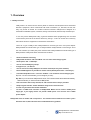
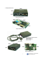
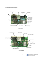
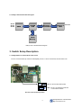
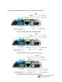
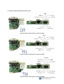
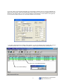
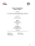
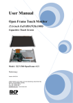
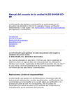
NetEye1000 Series® User Manual Version 2.51
NetEye1000SA
NetEye1000SB
NetEye1000HA
NetEye1000HB
Firmware Ver.
Ver. 2.00sc
External Type using power adapter
Internal Type
External Type power module included
Internal Type
NetEye 1000 SA
SM Information & Communication
Homepage
Technical Support
Sales Support
Address
:http://www.smic21.com
: +82-31-719-2201 [email protected]
: +82-2-6292-2100 [email protected]
: A-705, SK TwinTechTower, 345-9 Gasan-Dong, Kumchun-Gu, Seoul, Korea
Zip 153-023
SM Information & Communication
Http://www.smic21.com
Contents
1.Overview
1.1 NetEye Overview
4
1.2 NetEye1000Dimension
5
2. Specification
2.1NetEye1000 Specification
6
2.2 RJ45 Pin Description
6
2.3 DB9 Connector Pin Description
7
2.4 Status LED Description
7
2.5 NetEye1000 Hardware Description
8
2.6 NetEye1000 Hardware Block diagram
9
3. Switch Setup Description
3.1 NetEye1000S Pin Power switch select
9
3.2 NetEye1000S RS232/422/485 Piano Switch select and DB9 connector pin spec
10
3.3 NetEye1000H RS232/422/485 Dipswitch select
11
4. Setup Utility Software
4.1 NetEye1000 Setup Utility Software
12
4.2 Remote Setup
14
4.3 DHCP Setup
16
4.4 ToolMenu
17
SM Information & Communication
Http://www.smic21.com
SM Information & Communication Inc All rights reserved. No warranty is provided and no liability is
assumed by SM Information & Communication Inc. with respect to the accuracy of this documentation
or the merchantability or fitness of the product for a particular application, No license of any kind is
conveyed by SM Information & Communication with respect to its intellectual property of that of
others. All information in this document is subject to change without notice.
All other trademarks mentioned in this document are property of their respective companies.
Technical Support
SM Information & Communication R&D center
Address
: C-225 SIGMAII Gumidong, BundangGu SeongNamgu Gyunggido, Korea
Tel
:(8231) 621-2271
Fax
: (8231) 719-2281
E-mail
: [email protected]
Web Site : www.smic21.com
Sales Request
SM Information & Communication Head Office
Address
: A-705 SK Twin Tech Tower, 345-9 Gasandong, Kumcheongu, Seoul Korea
Telephone : (822)6292-2100~7
Fax
: (822)6292-2108
E-mail
:[email protected]
Environmnets
Input Voltage
: DC6~12 V from general Power Adapter
DC 5V for Pin No 6 of DB 9 serial connector. (pin power)
Input current
: max 200mA
Storage Humidity : 0 ~ 95%
Operating Temp: 0 ~ 70 °C
Storage Temp
: -20~70 °C
3
SM Information & Communication
Http://www.smic21.com
1. Overview
1.1 NetEye Overview
NetEye1000 is an internet access device (Serial To Ethernet Converter)with which stand-alone
electronic equipments, which communicate with serial connections (i.e., RS-232C, RS-422, RS485), may access to internet via 10 Base-T Ethernet Interface. NetEye1000 is designed as a
subminiature embedded system, card-sized, having TCP/IP kernel, Ethernet Chip and Serial port.
A user may access NetEye1000 using a general standard socket programming and use serial
communication protocols for the device without any change. A user can monitor and control any
stand-alone electronic equipments in the Network circumstance.
There are 4 type of NetEye 1000. NetEye1000SA is external type and it uses power adapter.
NetEye1000SB is internal board type of NetEye1000SA. NetEye1000HA is external type and it
has a 84~264VAC (47~440hz) free power module inside. NetEye1000HB is internal board type of
NetEye1000HA. Neteye1000 series have features as follows.
9
Serial To Ethernet Converting.
9
NetEye1000 has Server and Client Mode. You can select from setup program.
9
Serial Speed : 300 ~ 115200 bps.
9
You can search NetEyes by Group.
9
It supports 5, 6, 7, 8 data bit.
9
You can search and setup NetEyes from remote network(not only same network).
9
Password Management is possible for remote search.(default password is “smicneteye”) .
9
Connection Expiration Time : 0 second ~ Endless : You can define it from setup program.
Exp Time : 40 sec is recommended. (you can change as you want.)
Exp Time: If you do not access NetEye1000 for 40 sec, TCP connection will be disconnected automatically.
After disconnection, you should reconnect to NetEye1000.
9
TCP Connection status Lamp with RX, TX and Collision Detect Lamp is provided.
9
Setup Program includes Socket Simulation Program for convenient test.
9
It works very well with various Hub and Router.
9
Pin No 6. of DB9 serial connector of NetEye1000S Model can be used as +5VDC power
supply pin, if your legacy device can provide +5VDC power. You can also use 6~10VDC
power adapter.
NetEye1000 series is reliable and not expensive . It is tested at various fields for more than 3 years.
And more than 10,000 units have been installed without any problem.
4
SM Information & Communication
Http://www.smic21.com
1.2 NetEye1000 Dimension.
98mm
54mm
25mm
NetEye1000SA Dimension
50mm
93mm
57mm
NetEye1000SB Dimension
- 85~264 AC Power Module Included
- Aluminum Case
- Power On/Off Switch
- Guide Included
NetEye1000HA
155mm
100mm
57mm
50mm
42mm
90mm
NetEye1000HA Dimension
NetEye1000HB Dimension
5
SM Information & Communication
Http://www.smic21.com
2. Specification
2.1. NetEye1000 Hardware Specification
Item
NetEye1000
CPU
(8-Bit Micro Controller, 50MIPS)
Memory
4Kbytes Program Memory
256Bytes SRAM (Data Memory)
512K Bytes Flash Memory ( System Parameter)
Network Hardware
10 Base-T Ethernet Interface (IEEE 802.3)
RS232, 422, 485 (Serial 1 port)
Network Protocol
TCP/UDP
IP/ICMP/ARP
IEEE802.3(STANDARD ETHERNET)
Utility Software
NetEye Setup Utility Software (Windows 98/ME/NT/2000/XP)
NetEye Search, IP Setup, Built-In on Network.
Test Result Display
Simulation Program
NetEye1000 Specification
2.2. RJ45 Pin Description
Pin No.
Description
Color
1
TX+
White with Orange
2
TX-
Orange
3
RX+
White with Green
4
NOT USED
Blue
5
NOT USED
White with Blue
6
RX-
Green
7
NOT USED
White with Brown
8
NOT USED
Brown
3.RX+
4.NU
5.NU
2.TX-
6.RX7.NU
1.TX+
8.NU
RJ45 Pin Configuration
RJ45 Connector Pin Description
6
SM Information & Communication
Http://www.smic21.com
2.3. DB9 Connector Pin Description
Pin
Number
Signal
Description
Function
1.
TRX+
RS485+
Difference + Signal for RS485
2.
RXD
RS232 Recv
Data Recv for RS232
RX+
RS422 Recv+
Data Recv+ for RS422
TXD
RS232 Send
Data Send for RS232
TX+
RS422 Send+
Data Send+ for RS422
4.
TRX-
RS485-
Difference + Signal for RS485
5.
GND
Ground
Signal Ground
6.
CTS
Clear To Send For RS232C
Clear To Send Input for RS232 (not used)
PWR
+5V DC Power Pin
Can be used Power Supply Pin with Dip Switch
7.
RX-
RS422 Recv-
Data Recv -for RS422
8.
TX-
RS422 Send-
Data Send – for RS422
9.
RTS
Ready To Send for RS232C
Ready To Send Output for RS232 (not used)
3.
NetEye 1000 DB9 Connector Pin Description
2.4. Status LED Description
LED
Color/U-No
Description
TX
Green/D1
It light on when Power is On. And it blinks in the normal connection only
when NetEye send data to PC indicating the Ethernet Controller
(RTL8019AS) is sending data to a network.
RX
Green/D2
It light on when Power is On. It Indicates that the Ethernet controller is
receiving data from a network. It is blinking frequency changes subject to the
traffic volume of a network.
CD
(Collision)
Yellow/D3
Indicating that an Ethernet packet sending from the Ethernet controller to a
network collides with another one from other devices or computers. In this
case the Ethernet controller resends the collided packet automatically after
the lapse of specified period.
TCP
(Establish,
Power)
Orange/D4
When Power is On, it blinks during 3 seconds for Arp table update of general
router and out. It is Indicating that NetEye 1000S is connected to the user's
PC via a TCP Port Number. When connection between NetEye and PC
Program is established, the LED is on.
NetEye 1000 LED Description
7
SM Information & Communication
Http://www.smic21.com
2.5 . NetEye1000 Hardware Description
9Pin Serial Port
RJ45 LAN Port
Pin No. 6
Power Select Switch
Power Adapter
6~10VDC
RS422/232/485
Piano Switch
Status LED
+5VDC Power
RS232 Rx Pin
(TTL Signal)
UART
RS232 TX Pin
(TTL Signal)
GND
512K Flash Memory
Ethernet Chip
CPU 50MHz
NetEye1000SB
9Pin Serial Port
RJ45 Lan Port
Status LED
Power Line 5VDC
RS422/232/485
Select Dip Switch
+5VDC Power
RS232 Rx Pin
(TTL Signal)
RS232 Tx Pin
(TTL Signal)
UART
GND
512K Flash Memory
CPU 50MHz
Ethernet Chip
NetEye1000HB
8
SM Information & Communication
Http://www.smic21.com
2.6. NetEye 1000 Hardware Block Diagram
RS232
RS422
RS485
UART
SX52B
CPU
Ethernet
Controller
10base10base-T
Filter
Ethernet
Flash
Memory
NetEye 1000 Hardware Block Diagram
3. Switch Setup Description
3.1. NetEye1000S Pin Power Mode switch select
If Pin No.6 Power Select Dip switch is selected(ON), Pin No 6. can be used Power, Normal status is On.
ON : Pin No.6 Power Mode Select
OFF : Pin No.6 CTS Mode for RS232C
or Not Used for RS422
Pin No.6 Power Select Dip switch
9
SM Information & Communication
Http://www.smic21.com
3.2. NetEye 1000S RS232/422/485 Piano Switch Select and DB9 connector Pin Spec
Piano Switch Select and Serial Port Pin Spec for RS232
Piano Switch Select and Serial Port Pin Spec for RS422
Piano Switch Select and Serial Port Pin Spec for RS485
10
SM Information & Communication
Http://www.smic21.com
3.3. NetEye 1000H RS232/422/485 Dip Switch Select
Dip Switch Select and Serial Port Pin Spec for RS232
Dip Switch Select and Serial Port Pin Spec for RS422
Dip Switch Select and Serial Port Pin Spec for RS485
SM Information & Communication
11
Http://www.smic21.com
4. Setup Utility Software
4.1. NetEye1000 Setup Utility Software
1.
Connect NetEye1000 to your Network and Power On.
2.
Download Setup Utility software v.2.18 from www.smic21.com download Field.
3.
Install and execute it.
4.
If you have any NetEye1000 on your network, you must see the NetEye item on your screen
automatically.
5.
If you double click any Neteye1000S, you can see Device Setup Dialog Box.
6.
Change parameters as you want.
7.
Your setup ends by clicking OK button.
Local Search All: Search all NetEye1000 on the same network.
Local Search Group: Search NetEye1000 by Group ID.
Local Edit: Run Device Setup dialog Box and Edit parameters.
Remote Enable: Enable remote mode,
Remote Disable: Disable remote mode
12
SM Information & Communication
Http://www.smic21.com
If you click “Client” on Device Seup Dialog Box, the Client Mode is selected. And you can input Application IP
address and Port Number. When Client Mode NetEye starts, NetEye try to connect to the Application IP and Port
Number as TCP client process. You can connect to NetEye on client Mode by Connect button on the right side.
It is very useful for client mode test. Try to test with simulator in the Tool menu.
If you click “Local Search Group” NetEye Setup Program, you can see following Group ID Dialog Box, And you
can select Group ID from “A” to “Z”, When you select “A”, Setup Program searches only by Group ID ”A”
Green color: TCP Established NetEye
Blue color: Selected NetEye
13
SM Information & Communication
Http://www.smic21.com
4.2. Remote Set-up
Remote Enable: Click Enable remote Button, you can see Password Input Box. Default Password is
“smicneteye”. Input password and click OK button, You can change your password.
Remote Enable: Enable remote mode,
Remote Buttons will be enabled and remote Set-up file folder is added on the screen.
Remote Enable
Remote Disable
Remote Edit
Remote IP Search Again
14
SM Information & Communication
Http://www.smic21.com
Remote Enable
Remote Disable
Remote Edit
Remote IP Search Again
If you click Remote search IP button, Remote Setup Box
is displayed.
Input Remote NetEye IP address and click Add button.
You can input multi remote NetEyes IP address. OK
button make to search remote NetEyes and display on
the screen.
15
SM Information & Communication
Http://www.smic21.com
4.3. DHCP Set-up
DHCP Enable
DHCP Edit
Remote Disable
DHCP version NetEye has different firmware. In local search, Firmware version (F/W Ver) fields is DHCP.
When you are in DHCP file folder menu, if DHCP NetEyes are connected to Network, it send the IP
Information to the server computer. DHCP NetEyes should be setup
the server computer IP address
(Application IP address), at local Edit mode,in advance by system,such as window2000 server, with DHCP
server fucntion.
16
SM Information & Communication
Http://www.smic21.com
4.4. Tool Menu
Socket simulator program Menu.
Tool in the Menu Bar has a simulator popup menu. It starts socket simulator program with which you can
send and receive message by socket program.
With this simulator, you can simulate devices such as PLC, special machine. You can send 0x03,(STX),
Data, 0x04(ETX) with various time interval.
17
SM Information & Communication
Http://www.smic21.com