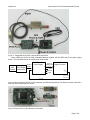
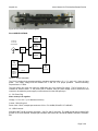
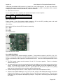
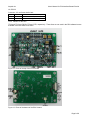
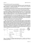
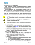
1
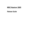
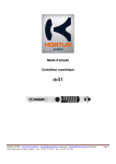
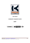
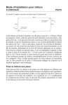
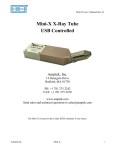
Amptek Inc. User’s Manual for PC4 Interface Boards Rev A4 PC4 INTERFACE BOARDS Amptek’s DP4 Digital Pulse Processor is a component in the complete signal processing chain of a nuclear instrumentation system. It must be used with other components, including (at a minimum) a detector and preamplifier, a computer with a serial interface (RS232 or USB) and software to communicate, and a power supply. The DP4 does not have any power supplies and does not have standard serial connectors. Amptek provides two different boards which may be used to connect the DP4 to a computer and power supplies. Both boards connect to the DP4 using a 16 position, 1 mm flex connector and pass the serial signals, RS232 and USB, straight through to more common connectors. The boards differ in how they handle power: PC4-2: Provides power to the DP4 from a +5 VDC source, either the USB bus or an external supply. This board has standard USB and RS232 serial connectors and a DC power socket. It supplies the three voltages that the DP4 requires, + 3.3 V, +5 V, and – 5 V. PC4-3: Provides power to both the DP4 and Amptek’s XR-100 detectors from a +5 VDC source. This board is intended for those using Amptek’s detectors and preamps. It has a standard USB connector but otherwise uses 0.1” connectors. The USB interface cannot supply enough current to operate the XR100, so an external DC supply is required, which must be between 3.5 V and 5.5 V. USB or RS232 Serial Detector Preamp DP4 PC4-2 +/-5V, +3.3V +5VDC USB or separate Preamp and Detector Power Amptek AXR Detector Amptek preamp XR100 or PC210 USB or RS232 Serial DP4 PC4-3 +/-5V, +3.3V +5VDC Preamp and Detector Power HV Bias, TEC, LV Figure 1. Block diagram of the two different DP4 Interface boards. Figure 2. Photograph of the PC4-2 with the DP4. Page 1 of 8 Amptek Inc. User’s Manual for PC4 Interface Boards Rev A4 Figure 3. Photograph of the PC4-3 with the DP4 and XR100. Many OEMs use the PA-210/230 preamplifier/detector together with the DP4 and PC4-3 power supply board. This total OEM solution is configured as shown below. Amptek AXR Detector Amptek PA-210/230J1 Preamplifier PC4-3 Power Supply Signal & Power flex cable Power & USB/RS-232 J1 J4A J3 OUT J5 flex cable +5VDC RS232 DP4 Digital Processor JP6 INPUT JP7 USB Signal to pin 1 Shield to pin 2 Signal coax cable Figure 4. Block diagram of the PC4-3, DP4, detector, and PA210/230 preamp. The detector must be used with a heat-sink like the right angle one shown. Figure 5. Photo of PC4-3, DP4, Detector, PA210/230. Page 2 of 8 Amptek Inc. User’s Manual for PC4 Interface Boards Rev A4 Figure 6. PC4-3 and DP4 stacked together. PC4-2 SPECIFICATIONS +3.3V Supply Power In 2.5 to 5.5V Center GND Auto Switch +5V Supply -5V Supply J2 USB Connector P1 RS232 Connector 9 pin D JP2 DP4 Connector RS232 Figure 7. PC4-2 Schematic The PC4-2 contains three separate switching regulators which produce +5 V, -5 V, and +3.3 V from the input power. The supply voltage must be between 2.5 V and 5.5 V for proper operation. Nominal switching frequencies are >1 MHz. The input power can come from either the USB power pin or an external DC supply. The DC power plug, J1, contains an internal switch. If the power jack is inserted, then the power supply current comes from this connector, otherwise the power supply current is drawn from the USB power pin. J1: DC Power Plug Note: center pin is negative. Voltage: 2.5 V to 5.5 V (6 V absolute maximum) Current: 500 mW typical Power Jack: 2.5mm, example part numbers: CUI Inc. PJ-102BH, DIGI-KEY CP-102B-ND J2: USB Connector Standard USB Type B connector receptacle. Only D+ and D- are used. The USB ground may be tied to DP4 ground via J2 or left isolated. Example part numbers: MILL-MAX: 897-30-004-90-000000, DIGI-KEY: ED90003ND. Page 3 of 8 Amptek Inc. User’s Manual for PC4 Interface Boards Rev A4 Underneath the standard USB connector is a footprint for a mini USB connector. The user may remove the standard USB connector and install a mini USB connector. Mini USB 1.1 (USB 2.0 compatible) 5 pin receptacle example part numbers: HIROSE UX60-MB-5ST, DIGI-KEY H2959TR. P1: RS232 Serial Connector 2.5 mm Stereo Audio Jack, compatible with standard serial ports on most computers. Tip Transmit To PC Receive, DB9 pin 2, DB25 pin 3 Ring Receive To PC Transmit, DB9 pin 3, DB25 pin 2 Sleeve Ground To PC Ground, DB9 pin 5, DB25 pin 7 JP2 : DP4 Connector Sixteen contact, 1 mm, flex connector which connects to JP6 on the DP4, providing power and serial connections. The pinout is described in the DP4 User Manual. JP4: I2C Bus Brings out the I2C lines from the DP4 for ease in customizing. Pin 1 : GND Pin 2: SCL Pin 3: SDA Pin 4: System Reset Figure 8. Photo of the PC4-2. PC4-3 SPECIFICATIONS The PC4-3 contains seven separate switching regulators. Three provide the power for the DP4: +3.3V, +5V, and -5V. Four provide the power for the XR100 preamp and detector: two low voltages for the preamplifier, the HV bias for the detector, and the power for the thermoelectric cooler. There are several important details for this circuit. The PC4-3 supply voltage must be between 2.5 and 5.5 V for proper operation. There is an absolute maximum rating of 6 V. The input power must come from an external DC supply (the USB bus cannot supply enough current for the cooler). The actual power consumed will depend on many variables, such as the temperature set point, whether a one or two stage cooler is used, etc. Typical values are 500 mA at 5 V (1 A at 2.5 V) steady stage, with an initial transient of twice this during the first 30-60 seconds. Nominal switching frequencies are >1 MHz, except for the HV bias, which switches at 50 kHz. There are two separate disable pins. If pin 5 of J3 is low, all four of the XR100 power supply circuits, are disabled, while making pin 7 of J3 low disables all three of the DP4 power supply circuits. These pins may be driven by logic or jumpered to the adjacent ground pins. If they float or are held high, the power supplies are enabled. Page 4 of 8 Amptek Inc. User’s Manual for PC4 Interface Boards Rev A4 1 Power In 2.5 to 5.5V 2 3 RS232-TX 4 RS232-RX 5 XR100 Disable 6 7 +3.3V Supply +LV Supply +5V Supply -LV Supply -5V or -8.5V -5V Supply HV Bias 0 to 400V +5V or +8.5V DP4 Disable 8 J3 Thermoelectric Cooler Supply J5 USB Connector J1 DP4 Connector Temperature J4 XR100 Connector Figure 9. PC4-3 Schematic Low Voltage Preamplifier Supplies The LV supplies for the preamp can be set to provide either +/-5 V or +/-8.5 V. The proper voltage depends on which Amptek preamplifier is used. If a jumper is installed in postion JP2, then the preamp receives +/- 8.5 V. If a jumper is installed in position JP1, the preamp receives +/-5 V. HV Bias Supply Discussion The control circuit for the HV supply is shown in the schematic below. TP18 measures the HV set point while TP20 measures the actual HV bias. Both measure 50 mV/Vbias, so for 100 V bias these test points should be at 2.0 V. Pot VR3 can be adjusted to the proper set point, or if the set point is known, resistors can be installed in R51 and R55 (the board is shipped with R51 and R55 not installed). The bias should be selected based on the detector in use. Oscillator Bias 0 to 400V RC Filter Multiplier 30 MEG 100MEG 1MEG 5V TP20 R51 VR3 Error Amplifier TP18 R55 Figure 10. Schematic for HV Bias supply circuit. TP18 measures the set point, while TP20 measures the actual bias at 50 mV/Vbias relative to high voltage. For 100 V bias, TP18 and TP20 should measure 2.0 V. Page 5 of 8 Amptek Inc. User’s Manual for PC4 Interface Boards Rev A4 The RC filter has a series resistance of 30 MΩ. This provides some current limiting, but it also means that the bias cannot be accurately measured at this node with a conventional DVM. Most DVMs have an input impedance of approximately 10 MΩ, so will only measure a fraction of the actual voltage. Thermoelectric Cooler Discussion The control circuit for the thermoelectric cooler is shown in the schematic below. This circuit maintains a fixed temperature rather than a fixed output voltage. A temperature sensor is located in the detector hybrid. The conditioning circuitry generates an output of 10 mV/K. This is compared to the set point to generate the error signal. Supply TEC Power RC Filter Temperature Sensor Conditioning 3.3 V TP1 R9 VR2 10K Error Amplifier TP8 R31 R30 15K Figure 11. Schematic for thermoelectric cooler supply circuit. The board is shipped with R9 and R31 not installed, so VR2 adjusts the set point. TP8 measures the set point while TP1 measures the actual temperature. Both are in units of 10 mV/K, i.e. a 250 K temperature yields 2.5 V. There exists a maximum temperature differential which a given cooler can achieve. If the set point is lower than this, then the supply will provide maximal cooling (with an output current limit) but the detector temperature is no longer regulated. It will change as the system temperature changes. A two stage cooler can typically reach a temperature of about 220 K under normal, laboratory conditions. Amptek detectors use a diode temperature sensor that must be calibrated. This has been done at the factory, but if the calibration is lost the procedure is: 1. Locate TMPSET and read the voltage with a multimeter. 2. Adjust VR2 until the voltage reaches its maximum voltage of approximately 3.25 volts. 3. Disconnect the multimeter. 4. Connect a detector to the PC4-3. The detector will now be at room temperature. 5. Locate TMON and read the voltage with a multimeter. 6. Adjust VR1 until the voltage on TMON matches room temperature (i.e. 293 K = 2.93 V). 7. Disconnect the multimeter. 8. Locate TMPSET and connect the multimeter. 9. Adjust VR2 until the voltage reaches your required temperature set point. See above for 1 and 2-stage cooler temperature ranges. 10. Disconnect multimeter. 11. Diode calibration is now complete. Page 6 of 8 Amptek Inc. User’s Manual for PC4 Interface Boards Rev A4 Connectors, Test Points, and Specifications J1 : DP4 Connector Sixteen contact, 1 mm, flex connector which connects to JP6 on the DP4, providing power and serial connections. The J1 connector is mirrored relative to the DP4, so that a straight through flex cable may be used. The pinout is described in the DP4 User Manual. J2: I2C Bus Brings out the I2C lines from the DP4 for ease in customizing. J3: Power and RS232 Connector: 2x4 right angle header. Molex P/N 71764-0108. Pin 1: Ground Pin 2: Power In. Provides power to the PC4-3. Must be 2.5 to 5.5 V. At 5 V, typical current is 500 mA steady state and 1A initial. Pin 3: RS232-TX (output from DP4) Pin 4: RS232-RX (input to DP4) Pin 5: XR100 Shut Down. Holding this pin low turns off the supplies to the XR100 preamp and detector. Pin 6: Ground Pin 7: DP4 Shut Down. Holding this pin low turns off the supplies to the DP4. Pin 8: Ground J4: Power Connector to XR100 Connector: 1x6 right angle header. Molex P/N 22-28-8062. Pin 1: Detector temperature. This is an input to the PC4-3 from the XR100 Pin 2: HV Bias. From 0 to 500 V, depending on the detector. Pin 3: -8.5 or -5 V. Supplies power to the XR100 preamp Pin 4: +8.5 or +5 V. Supplies power to the XR100 preamp Pin 5: Ground Pin 6: TC+. Provides power to the thermoelectric cooler. Should not exceed 4 V for two stage cooler. See detector specifications for details. J4A: Power Connector to PA210/PA230 Connector: 1 mm 10 pin connector: Samtec P/N ZF1-10-01-T-WT. NOTE: The connector does not have contacts on both sides. Connect the flex cable accordingly such that the contacts on the flex cable connect to the contacts in the connector. Pin 1: -TC (return) Pin 2: +TC Pin 3: +5 V preamp power Pin 4: -5 V preamp power Pin 5: Ground Pin 6: Signal Out Pin 7: Detector temperature. Pin 8: Ground Pin 9: N.C. Pin 10: HV Bias J5: USB Connector Standard Mini USB 1.1 (USB 2.0 compatible) 5 pin receptacle. D+, D-, and ground are connected. USB power comes to TP19 but is not used. Example part numbers: HIROSE UX60-MB-5ST, DIGI-KEY H2959TR. Page 7 of 8 Amptek Inc. User’s Manual for PC4 Interface Boards Rev A4 J6: RS-232 Connector: 2.5 mm Stereo Audio Jack Tip Transmit To PC Receive, DB9 pin 2, DB25 pin 3 Ring Receive To PC Transmit, DB9 pin 3, DB25 pin 2 Sleeve Ground To PC Ground, DB9 pin 5, DB25 pin 7 TP13: /RESET for the DP4 TP10 and TP12 are RS232-CTS and -RTS, respectively. These lines are not used in the DP4 software but are available if the user wants to use them. Figure 12. Photo of the top of the PC4-3 board. Figure 13. Photo of the bottom of the PC4-3 board. Page 8 of 8