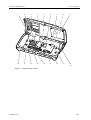
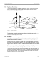
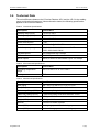
1
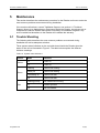
ZSE SOFTWARE & ENGINEERING
WWW.ZSE.IT
TECNOLOGIE
CONTROLLO ACCESSI
MANUAL
LR-series Installation Manual
REFERENCE
ZSE SOFTWARE & ENGINEERING
VIA M. IDIOMI 10/O
20090 ASSAGO (MI) ITALY
Doc no. 06-136 02
© TagMaster AB
LR-series Installation Manual
Doc no. 06-136 02
注意 !
依據 低功率電波輻射性電機管理辦法
第十二條 經型式認證合格之低功率射頻電機,非經許可,公司、商號或使用
者均不得擅自變更頻率、加大功率或變更原設計之特性及功能。
第十四條 低功率射頻電機之使用不得影響飛航安全及干擾合法通信;經發現
有干擾現象時,應立即停用,並改善至無干擾時方得繼續使用。
前項合法通信,指依電信規定作業之無線電信。低功率射頻電機須忍
受合法通信或工業、科學及醫療用電波輻射性電機設備之干擾。
Copyright
The copyright and ownership of this document belongs to TagMaster AB. The document may be
downloaded or copied provided that all copies contain the full information from the complete document. All
other copying requires a written approval from TagMaster AB.
Disclaimer
While effort has been taken to ensure the accuracy of the information in this document TagMaster AB
assumes no responsibility for any errors or omissions, or for damages resulting from the use of the
information contained herein. The information in this document is subject to change without notice.
© TagMaster AB
2 (26)
LR-series Installation Manual
1
Introduction
Doc no. 06-136 02
4
2
Safety Instructions
5
2.1
Warnings ........................................................................................................ 5
3
General Information
6
3.1
Reader Overview............................................................................................ 6
3.2
System Overview ........................................................................................... 9
3.3
ID-tags............................................................................................................ 9
3.4
Reader.......................................................................................................... 10
3.5
Environmental Considerations ..................................................................... 10
3.5.1
Electromagnetic Interference................................................................ 10
3.5.2
Electromagnetic Interference in Cables................................................ 10
3.5.3
Lightning ............................................................................................... 10
3.5.4
Temperature ......................................................................................... 10
3.6
Technical Data ............................................................................................. 11
4
Installation
12
4.1
Preconditions................................................................................................ 12
4.1.1
Tools..................................................................................................... 12
4.1.2
Cables .................................................................................................. 12
4.2
Mounting the Reader.................................................................................... 13
4.3
Cable Connections ....................................................................................... 15
4.3.1
Relay Output, Group J1........................................................................ 18
4.3.2
Wiegand/Mag-stripe, Group J2............................................................. 18
4.3.3
Power Supply, Group J31..................................................................... 19
4.3.4
External Tamper Switch, Group J32..................................................... 19
4.3.5
RS485 Serial Communication Interface, Group J41............................. 20
4.3.6
RS232 Serial Communication Interface, Group J42............................. 20
4.3.7
Service Interface, Group J43................................................................ 20
4.3.8
Isolated Inputs, Group J51 ................................................................... 21
4.3.9
Isolated Outputs, Group J52................................................................. 21
4.3.10
Ethernet, Connector P1 ........................................................................ 21
4.3.11
USB Host, Connector P2...................................................................... 21
4.3.12
Micro SD Memory Card Interface, Socket P3....................................... 21
4.4
Installation Test ............................................................................................ 22
4.4.1
Inspection ............................................................................................. 22
4.4.2
Verification............................................................................................ 22
5
Maintenance
23
5.1
Trouble Shooting .......................................................................................... 23
6
Contact
25
6.1
Technical Support ........................................................................................ 25
6.2
Office ............................................................................................................ 25
7
© TagMaster AB
Glossary
26
3 (26)
LR-series Installation Manual
1
Doc no. 06-136 02
Introduction
This section introduces the LR-series Reader and defines the target group for this
manual.
The LR-series Reader is a long range Radio Frequency Identification (RFID) device for
remote identification of ID-tags. The Reader can be used as a stand-alone reading
device, or incorporated in more comprehensive identification systems through several
standard interfaces.
The target group for the LR-series Installation Manual is personnel installing LR-series
Reader, that is mounting the unit, installing the necessary cables, and performing an
installation test. A sufficient knowledge of English is necessary.
The aim of the manual is to present an installation engineer, who has the necessary
education and training, with the information needed to correctly install the LR-series
Reader.
Note: This manual does not describe how to configure Reader application software,
consult the corresponding software manual for more information.
© TagMaster AB
4 (26)
LR-series Installation Manual
2
Doc no. 06-136 02
Safety Instructions
This section describes general safety instructions and shows the system used for
presenting safety information.
Read this manual carefully before installation work is performed and take notice of
warnings in order to prevent injury and product damage.
Where local regulations exist, these are to be followed. The safety information in this
manual is a supplement to local regulations. It is the responsibility of the local project
manager to make certain that local regulations are known and followed.
The relevant manual (including this safety information) must be followed in any work
performed on the TagMaster products or systems.
The use of TagMaster’s genuine spare parts is recommended. TagMaster will not
assume responsibility for any malfunction due to use of spare parts produced by a third
party.
2.1
Warnings
Warnings are used throughout this manual to alert the reader to special instructions
concerning a particular task or operation that may be hazardous if performed
incorrectly or carelessly. The warnings are preceded by the common hazard symbol.
Figure 1 Hazard Symbol
The following two levels of warnings are used:
Warning!
Warning means that an accident may occur if the safety precautions are neglected.
This type of accident may cause injury. It may also damage the product.
Caution!
Caution means that an accident may occur if the safety precautions are neglected. This
type of accident may damage the product.
© TagMaster AB
5 (26)
LR-series Installation Manual
3
Doc no. 06-136 02
General Information
This section illustrates the Reader in particular and the identification system with its
components in general. Environmental considerations as well as technical data are
also described.
Check the contents of the shipment for completeness and possible damage. If the
contents are damaged, file a claim immediately with the carrier and the TagMaster
sales or service organisation. Alternatively notify a TagMaster representative in order to
facilitate repair or replacement of the equipment.
3.1
Reader Overview
The LR-series Reader is designed for configuration with a wide range of input and
output devices, including relays, isolated I/O, indicators, and a buzzer.
The Reader has several communication alternatives and is easily integrated using the
following communication interfaces:
•
•
•
•
•
•
Ethernet
RS232
RS485
USB Host
Wiegand/Mag-stripe
Micro SD memory card
Note: the Reader application software may not be designed to support the use of these
interfaces, consult corresponding software manual for further information.
The Reader is powered with a voltage ranging from +10 to +30 V DC.
© TagMaster AB
6 (26)
LR-series Installation Manual
Doc no. 06-136 02
1
2
3
4
5
6
7
8
9
10
11
12
13
14
15
16
17
18
TM00101
Figure 2 Overview of the Reader
© TagMaster AB
7 (26)
LR-series Installation Manual
Doc no. 06-136 02
The following table describes the position of the components inside the Reader.
Table 1 The components of the Reader
Number
Component
1
Lid
2
Controller board
3
RF-unit
4
Externally-visible indicators
5
Tamper switches
6
Red system status indicator
7
Green system status indicator
8
Yellow system status indicator
9
TX-unit
10
Enclosure base
11
Chassis
12
Knock-out for cable entry
13
Terminal blocks
14
Ground screw
15
Ethernet connector with link state and activity indicators
16
Micro SD slot
17
USB host connector (intended for internal expansion)
18
Pressure balance membrane
© TagMaster AB
8 (26)
LR-series Installation Manual
3.2
Doc no. 06-136 02
System Overview
The two main elements of a TagMaster identification system are the Reader and the
ID-tag. Peripheral elements are for example a host computer and other external
devices, such as traffic lights and barriers.
TM00102
Figure 3 System Overview
The figure above shows the overview of a TagMaster identification system with a polemounted Reader, an ID-tag mounted on the inside of a car windscreen, a host
computer, a power supply, and a barrier.
3.3
ID-tags
An ID-tag is a device carrying ID information that can be read at a long distance. The
actual reading range depends on the type of the Reader, the ID-tag, settings of the
Reader, and environmental conditions.
Standard ID-tags have the shape of a credit card, but are slightly thicker. Each ID-tag
has its own unique mark and it is possible to read many ID-tags concurrently. A lithium
battery is used in the ID-tag to achieve a high communication speed and a long reading
range.
There are two types of ID-tags called ScriptTags and MarkTags. ScriptTags can both
be read from and written to, while MarkTags only can be read.
The front side of the ID-tags must be oriented towards the front side of the Reader. For
maximum communication range, the front surface of the ID-tag should be parallel with
the front side of the Reader. If the ID-tag is misaligned relative to the front side of the
Reader, the communication range is reduced.
© TagMaster AB
9 (26)
LR-series Installation Manual
3.4
Doc no. 06-136 02
Reader
The LR-series Reader is a device for reading ID-tags using 2.45 GHz frequencies. In
addition to reading, some Readers also have the capability to write information to
ScriptTags (see separate data sheet for specific capabilities of the Reader). The
Reader has built-in antennas for communication with ID-tags as well as various serial
interfaces for communication with a host computer.
3.5
Environmental Considerations
The LR-series technology is a reliable solution for identification systems because it is
unaffected by the normal electromagnetic background noise found in industries and
elsewhere.
3.5.1
Electromagnetic Interference
Industrial noise is typically present in the kHz and low MHz frequency band. The LRseries is using 2.45 GHz frequencies, so typical industrial noise will not affect the
communication.
3.5.2
Electromagnetic Interference in Cables
By using specified cables, proper shielding, and grounding as well as selecting a
suitable communication interface, optimum communication reliability is ensured. For
more information about cable specification see section 4.1.2 Cables.
3.5.3
Lightning
In order to protect the Reader from possible effects of lightning, additional surge
protection on the inputs and outputs can be needed.
3.5.4
Temperature
For most applications, normal convection cooling is sufficient for the Reader. But if heat
is generated close to the Reader, the use of forced cooling or heat shields should be
considered.
© TagMaster AB
10 (26)
LR-series Installation Manual
3.6
Doc no. 06-136 02
Technical Data
The main difference between the LR-series Readers LR-6 and the LR-3 is the reading
range and physical dimensions. Unless otherwise stated, the following specification
applies to all LR-series Readers.
Table 2 Functional Specifications
Description
Specification
Reading range (LR-6)
0–6 m or 0–20 ft
Reading range (LR-3)
0–3 m or 0–10 ft
Power supply
+10 to +30 V DC
Power consumption
4.5 W
Current consumption
175/350 mA @ 24/12 V DC
Radio frequency range
CW: 2436.1–2464.1 MHz, channel 5–97
FHSS: 2400–2483.5 MHz
Tag data speed
Low 4 kbps and high 16 kbps
Ethernet
10/100 Mbps
Serial outputs
RS232, 2-wire or 4-wire RS485. Up to 115.2 kbps.
Table 3 Environmental Specifications
Description
Specification
Operating temperature
range
−20°C to +60°C or −4°F to +140°F
Sealing
IP 65
Table 4 Mechanical Specifications
Description
Specification
Size (LR-6)
290 × 165 × 56 mm or 11.4 × 6.5 × 2.2 in
Size (LR-3)
228 × 145 × 50 mm or 8.9 × 5.7 × 2.0 in
Cable entry fittings (LR-6)
8 cable entry fitting holes with diameter 16 mm
Cable entry fittings (LR-3)
5 cable entry fitting holes with diameter 16 mm
Weight (LR-6)
0.95 kg or 2.1 lbs
Weight (LR-3)
0.74 kg or 1.6 lbs
Material
Enclosure is made of plastic
Colour (LR-6)
Lid is light grey and base is dark grey
Colour (LR-3)
Lid is medium grey and base is dark grey
© TagMaster AB
11 (26)
LR-series Installation Manual
4
Doc no. 06-136 02
Installation
This section describes the procedure of installing the Reader, that is mounting the
Reader, installing the necessary cables, and performing an installation test. Read
through this entire section before performing the installation.
The TagMaster system employs circular polarisation and can therefore also often be
used when metal surfaces are in the vicinity of the antenna and the ID-tag, especially if
the ID-tag is moving. In such cases however, adjustment of the Reader and the ID-tag
positions and distance may be necessary to find the best arrangement.
4.1
Preconditions
The locations of Readers and ID-tags have been specified during the project planning
phase, based on considerations of communication distances and movement speeds.
The cable paths and cable types have been determined during the project planning
phase.
The power supply must comply with all relevant safety regulations.
The equipment must be disconnected from all voltage sources before any installation
or service work is carried out. Capacitors inside the equipment can hold their charge
even if the equipment has been disconnected from all voltage sources.
Caution!
Damage may be the result if the equipment is switched on when parts are removed
from the controller board, or if a PCB is removed within one minute after switching off
the equipment.
4.1.1
Tools
The following tools are necessary for installation:
• Screwdriver, Torx T20
• Screwdriver, 2.5 mm flat-bladed
• Short metal tube, diameter 16 mm
• Hammer
• Side cutter
• Wire stripper
• Crimping tool for ferrules
4.1.2
Cables
Cables are not supplied with the LR-series.
All cables must be shielded and suitable for the installation environment, for instance
indoor or outdoor environment. Use flexible cables with stranded wire.
The terminal blocks used are Phoenix, type PT 1.5, which allow for a cable area of 0.2
to 1.5 mm² (AWG 26-14). Stranded wires must be fitted with a ferrule before being
inserted in the termination blocks.
© TagMaster AB
12 (26)
LR-series Installation Manual
Doc no. 06-136 02
The cable for the RS485 interface must be a twisted pair cable and conform to the EIA
RS485 standard.
A category 5 (CAT 5) cable is required for the Ethernet connection.
4.2
Mounting the Reader
Mount the Reader in a horizontal position. In exceptional cases, the Reader can be
mounted in a vertical position.
Mount the Reader on a bracket and direct the front side of the Reader so that the
reading lobe covers the positions of the ID-tags. The Reader identifies ID-tags within
the reading lobe that expands in front of the Reader.
For optimal performance, tilt and rotate the Reader into a position so that the front side
of the Reader is parallel with the front surface of the ID-tag to be read. Align the
Reader so that the actual reading range is 60–70% of the specified maximum reading
range.
The figure below shows a typical Reader installation, note that the installation details
depend on site requirements and type of Reader.
=
60 -
70%
100
%
=
TM00103
Figure 4 Reading lobe
The LR-series Reader is prepared for mounting directly in a bracket on the back side of
the Reader. The mounting holes enable the use of VESA 75 standard mounting
brackets.
There are several M4 holes which can be used to fasten the reader onto the mounting
bracket. The mounting holes are sealed at the base, so the fixing screw must not
extend more than 8 mm into the reader.
© TagMaster AB
13 (26)
LR-series Installation Manual
Doc no. 06-136 02
75
75
165
75
Note: Do not drill any additional holes in the enclosure, as that would affect the sealing
specification.
75
290
TM00104
145
75
Figure 5 LR-6 mounting hole layout on the back side of the Reader (units of measurement:
mm)
75
228
TM00105
Figure 6 LR-3 mounting hole layout on the back side of the Reader (units of measurement:
mm)
© TagMaster AB
14 (26)
LR-series Installation Manual
Doc no. 06-136 02
The Universal Mounting Kit (Part No. 193600) from TagMaster enables the
Reader to be mounted in a wide variety of positions and angles. The kit contains all
parts needed for mounting the Reader on a wall or on a pole. The Universal
Mounting Kit is suitable for both indoor and outdoor use. See separate data sheet
for more details.
Caution!
Never exceed the environmental and electrical limits as specified in section 3.6
Technical Data. Exceeding the limits can result in permanent damage to the Reader.
4.3
Cable Connections
The Reader is provided with knock-outs for incoming cables on both the horizontal and
vertical edges. First and foremost use the cable entries on the horizontal edge of the
Reader, even if the Reader is mounted in a vertical position.
Note: The Reader is certified for an installation of maximum four separate incoming
cables. Do not exceed this maximum number.
1. Use a short 16 mm-diameter tube to remove the desired knock-outs. Using a
hammer as illustrated in Figure 7, tap the tube sharply.
Caution!
Keep the Reader closed when knocking-out the cable entries to prevent damaging the
enclosure and be careful that the tube does not contact any components inside the
Reader.
© TagMaster AB
15 (26)
LR-series Installation Manual
Doc no. 06-136 02
TM00106
Figure 7 Knocking out the cable entries
2. Open the Reader using a Torx screwdriver.
3. Insert metal cable glands into the holes.
4. Cut the power cable to a suitable length and pull it through the cable gland as
illustrated in Figure 8.
5. Connect the shield of the power cable to earth at the power supply end. The
shield functions as earth connection for the Reader.
6. Measure enough length of the cable to reach to the terminal block.
7. Strip the outer insulation and pull back the cable until the cable shield makes
contact with the earthing fingers inside the gland.
8. Tighten the cable gland around the cable.
© TagMaster AB
16 (26)
LR-series Installation Manual
Doc no. 06-136 02
TM00108
Figure 8 Grounding the cable in the cable gland
9. Cut away excessive length of the cable shield, strip the ends of the conductors,
and crimp a ferrule onto the stripped end of each conductor.
10. Connect the power cable to group J31 according to Table 8.
11. Make sure that the power source is turned off and connect the other end of the
power cable to the power source.
12. Connect the remaining cables in the same manner. For connection of the
Ethernet cable, see also section 4.3.10 Ethernet, Connector P1.
Caution!
Do not remove pressure balance membrane; it will compromise the IP classification.
© TagMaster AB
17 (26)
LR-series Installation Manual
Doc no. 06-136 02
P2
P1
P3
123 12345612345 123412 1234
J1
J51
J52
J31 J32 J2
12345123 123
J41 J42 J43
TM00107
Figure 9 Controller board with external connections
Note: It is possible to attach or remove the terminal block connectors inside the Reader
for more convenient connection of the cables.
The terminals are grouped as specified in the sections below.
4.3.1
Relay Output, Group J1
The controller board has one relay output for heavy duty loads.
Table 5 Relay Output, Group J1
4.3.2
Pin
Signal
Description
1
RCOM
Common terminal or relay
2
ROPEN
Connected to RCOM when relay is open
3
RCLOSE
Connected to RCOM when relay is closed
Wiegand/Mag-stripe, Group J2
The controller board has an access control interface that supports both Wiegand and
Mag-stripe protocols.
Table 6 Wiegand, Group J2
Pin
Signal
Description
1
D0
Wiegand 0 (zero) signal
2
D1
Wiegand 1 signal
3
CL
Card load signal
4
GND
Ground
© TagMaster AB
18 (26)
LR-series Installation Manual
Doc no. 06-136 02
Table 7 Mag-stripe, Group J2
4.3.3
Pin
Signal
Description
1
CLK
Mag-stripe clock signal
2
DATA
Mag-stripe data signal
3
LOAD
Card load signal
4
GND
Ground
Power Supply, Group J31
Pin 1 is internally connected to pin 3 and pin 2 is internally connected to pin 4. The
purpose is to make it possible to feed power to any peripheral equipment. Use pins 1
and 2 for power supply connection.
Table 8 Power Supply, Group J31
4.3.4
Pin
Signal
Description
1
SPL
Positive DC supply input
2
RTN SPL
Negative DC supply input
3
SPL
Positive DC supply input, internally connected to pin 1
4
RTN SPL
Negative DC supply input, internally connected to pin 2
External Tamper Switch, Group J32
To protect the Reader from tampering, there are two mechanical tampering switches
which break if the cover is opened. One tamper switch is connected internally to the
controller board and will generate a software alarm when broken, and the other is an
external tamper switch interface which can be connected to an external alarm loop.
Table 9 External Tamper Switch, Group J32
Pin
Signal
Description
1
TAMP A
2
TAMP B
When the tamper switch is open, TAMP A and TAMP
B are connected.
© TagMaster AB
19 (26)
LR-series Installation Manual
4.3.5
Doc no. 06-136 02
RS485 Serial Communication Interface, Group J41
The controller board has one RS485 serial interface for both 2-wire and 4-wire
communication. RS485 supports multi-drop serial networks. The communication can
be in both full duplex (4-wire) and half duplex (2-wire).
Note: If the installation requires long cables or high data speeds it may be necessary to
use termination.
Table 10 Full Duplex (4-wire) RS485 Serial Communication Interface, Group J41
Pin
Signal
Description
1
TX+
Transmitted data, from Reader to Host
2
TX−
3
GND
Ground
4
RX+
Received data, to Reader from Host
5
RX−
Table 11 Half Duplex (2-wire) RS485 Serial Communication Interface, Group J41
4.3.6
Pin
Signal
Description
1
TX/RX+
Transmitted and received data, to and from Host
2
TX/RX−
3
GND
Ground
4
NC
Not used
5
NC
RS232 Serial Communication Interface, Group J42
The controller board has one RS232 serial interface.
Table 12 RS232 serial communication interface, Group J42
4.3.7
Pin
Signal
Description
1
TX
Transmitted data, from Reader to Host
2
RX
Received data, to Reader from Host
3
GND
Ground
Service Interface, Group J43
The service interface is used for maintenance and configuration of the Reader. Do not
use the service interface as a regular system interface.
Table 13 Service Interface, Group J43
Pin
Signal
Description
1
TX
Transmitted data, from Reader to Host
2
RX
Received data, to Reader from Host
3
GND
Ground
© TagMaster AB
20 (26)
LR-series Installation Manual
4.3.8
Doc no. 06-136 02
Isolated Inputs, Group J51
The Reader has three isolated optocoupler inputs which are protected from noisy
environments.
Table 14 Isolated Inputs, Group J51
4.3.9
Pin
Signal
Description
1
IN 1A
Input signal 1
2
IN 1C
Input reference 1
3
IN 2A
Input signal 2
4
IN 2C
Input reference 2
5
IN 3A
Input signal 3
6
IN 3C
Input reference 3
Isolated Outputs, Group J52
The reader has two open collector outputs.
Table 15 Isolated Outputs, Group J52
Pin
Signal
Description
1
OUT 1C
Output 1 collector
2
OUT 1E
Output 1 emitter
3
OUT SPL
External supply voltage for the outputs
4
OUT 2C
Output 2 collector
5
OUT 2E
Output 2 emitter
4.3.10 Ethernet, Connector P1
An RJ45 connector labelled P1, with two internal indicators, is provided for Ethernet
connection. The clip for detaching the cable faces upwards from the controller board
surface to allow mid-board mounts.
The Ethernet connector has eight pins and the wire scheme is based on the T568A
standard. The pins are wired straight through the cable, that is, pins 1 through 8 on one
end are connected to pins 1 through 8 on the other end.
Note: The RJ45 connector will not pass through the cable gland. Pass the Ethernet
cable through the cable gland, before crimping the connector on the cable.
4.3.11 USB Host, Connector P2
USB devices are connected using a standard USB type A connector.
4.3.12 Micro SD Memory Card Interface, Socket P3
A standard micro SD memory card socket is used. The card socket is placed on the
underside of the controller board.
© TagMaster AB
21 (26)
LR-series Installation Manual
4.4
Doc no. 06-136 02
Installation Test
After having completed the installation as described in previous sections, carry out an
installation inspection and verification. If an error occurs, the guidelines in section 5.1
Trouble Shooting may be valuable.
4.4.1
Inspection
Ensure that there are no metal objects between or close to the Reader and the ID-tag
in the positions where communication is to take place.
Ensure that the Reader and the ID-tag are aligned properly. Avoid communication at
maximum specified distance and misalignment, see Figure 4.
Ensure that the Reader is not placed in a location where it is exposed to excessive
heat or electromagnetic interference.
4.4.2
Verification
The installation verification is as follows:
1. Keep the lid of the Reader open.
2. Switch on power to the Reader.
3. Observe the behaviour of the system status indicators on the controller board.
The yellow, red, and green system status indicators will be on continuously.
4. The green system status indicator will start flashing after about 30 seconds,
indicating that the software is running.
5. The buzzer will sound a short beep and the red system status indicator will start
flashing when the hardware is initiated and running.
6. If the Reader is connected to an Ethernet network, the green link state indicator
on the Ethernet connector will be on to indicate a 100 Mbps connection or off to
indicate a 10 Mbps connection. The yellow activity indicator on the Ethernet
connector will be flashing to indicate present network communication.
If the hardware fails to initiate, the Reader will make two more attempts to initiate it.
Each attempt is indicated by a short beep. If the hardware does not initiate after three
attempts, contact TagMaster, see section 6.1 Technical Support.
If specific Reader application software is used, consult the corresponding software
manual for more information concerning installation test.
Close the Reader, fit the lid to the base enclosure, and fasten the screws on the lid.
Tighten the screws to a torque of 1 Nm in order to seal the enclosure without
destroying the gasket. Clean up the site and dispose of any debris from the work.
© TagMaster AB
22 (26)
LR-series Installation Manual
5
Doc no. 06-136 02
Maintenance
This section describes the maintenance procedure for the Reader and how to solve the
most common problems encountered during installation.
If the reader malfunctions, contact TagMaster Support, see section 6.1 Technical
Support. Never try to dismantle any components inside the Reader, since there are no
components inside the Reader that can be serviced by an installation engineer. Any
such unauthorized alterations to the Reader will invalidate the warranty.
5.1
Trouble Shooting
The following table describes the most common problems encountered during
installation as well as adequate solutions.
Three system status indicators on the controller board inside the Reader show the
status of the unit as illustrated in Figure 2. The table below explains the different
indicator meanings.
Table 16 System status indicators
Colour
Yellow
Green
Red
© TagMaster AB
Mode
Indicates
On
Power on
Off
Power off
Flashing
System SW running
Initially on
System SW loading
Persistently on
System SW fault
Off
System SW fault
Flashing quickly
HW initiated and running
On
Initiation process
Off
HW not initiated
23 (26)
LR-series Installation Manual
Doc no. 06-136 02
The link state indicator and the activity indicator on the Ethernet connector inside the
Reader show the status of the network communication as explained in the table below.
Figure 10 Ethernet indicators
Colour
Green
Yellow
Mode
Indicates
On
100 Mbps connection
Off
10 Mbps connection
Flashing
Present communication
On
Link exists
Off
No communication
The following table describes the most common problems encountered during
installation and proposed solutions.
Table 17 Most common problems
Problem
Solution
Yellow system status
indicator is off
Check the power supply.
Green system status
indicator is on or off
Switch off the power supply, switch it on again, and
wait 30 seconds. This can be done by pulling the J31
terminal block off the board and putting it back again.
If the Reader fails to start again, contact TagMaster
support.
Red system status indicator
is on or off
Switch off the power supply and switch it on again.
This can be done by pulling the J31 terminal block off
the board and putting it back again. If the Reader fails
to start again, contact TagMaster support.
Yellow Ethernet indicator is
off
Check the network connection.
© TagMaster AB
24 (26)
LR-series Installation Manual
6
Doc no. 06-136 02
Contact
For any further inquiries, please contact your reseller.
6.1
Technical Support
6.2
Office
ZSE SOFTWARE & ENGINEERING
WWW.ZSE.IT
TECNOLOGIE
CONTROLLO ACCESSI
© TagMaster AB
25 (26)
LR-series Installation Manual
7
Doc no. 06-136 02
Glossary
The glossary lists abbreviations and acronyms used in this manual.
AWG
American Wire Gauge
CW
Continuous Wave
DC
Direct Current
FCC
Federal Communications Commission
FHSS
Frequency-Hopping Spread Spectrum
Host
The external intelligence, for instance workstation or
server, which acts as master of a Reader or a set of
Readers
ID-tag
ID-carrier in the TagMaster system, which is readable
and writable using a Reader
Mag-stripe
Card reading protocol used for reading magnetic stripe
cards
PCB
Printed Circuit Board
Reader
TagMaster LR-series ID-tag reader
RF
Radio Frequency
RFID
Radio Frequency Identification
Tamper switch
Switch that detects unauthorized access to the unit
USB
Universal Serial Bus
VESA
Standard for mounting flat panel monitors and TVs,
also known as Flat Display Mounting Interface (FDMI)
Wiegand
Trade name for a technology used in card readers and
sensors, particularly for access control applications
© TagMaster AB
26 (26)


![MC67 with Android OS Regulatory Guide [English] (P/N](http://vs1.manualzilla.com/store/data/006172691_1-6bf2b190b974108e1e90d6cfbb5a65d7-150x150.png)