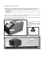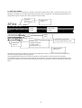
1
User Manual
Rel. 1.2
DATAPROCESS EUROPE S.p.A.
Viale Dell’Artigianato, 19
Binasco (MI)
Tel. +39- 02- 900221
Fax +39- 02- 90091353
UV515 GB
1
1.
GENERAL INSTRUCTIONS............................................................................................................................3
2.
DESCRIPTION OF THE PRINTER.................................................................................................................4
3.
UNPACKING AND INSPECTION ...................................................................................................................6
4.
LOADING THE LABEL ROLL AND THE RIBBON......................................................................................7
5.
CLEANING THE PRINTHEAD AND MECHANICAL PARTS .....................................................................9
6.
THE TEST LABEL..........................................................................................................................................10
7.
AUTOCALIBRATION ....................................................................................................................................11
8.
CALIBRATION ...............................................................................................................................................11
9.
TECHNICAL CHARACTERISTICS..............................................................................................................12
2
1. GENERAL INSTRUCTIONS
This manual should be read to take advantage of all the features of the printer and should then be kept for
future reference.
It is important to undertake periodic maintenance and, if necessary, any repairs should be undertaken at our
Head office or authorised Distributors, as they have the necessary equipment and properly trained staff to
undertake the work in accordance with instructions received from the factory.
DATAPROCESS EUROPE S.p.A. cannot be held responsible for any incorrect repairs or intervention by
unauthorised technicians nor for any damage resulting from the use of non original parts.
DATAPROCESS EUROPE S.p.A. is not responsible for any damage which can result, directly or indirectly,
to persons or things from an installation or use of the ST314 printer which is not in accordance with the
instructions contained in this manual.
WARNING
This symbol and the “WARNING” message are used to indicate important instructions for the use of the printer.
Serious damage can be caused by not adhering to these instructions.
WARNING
DO NOT DISMANTLE AND DO NOT MODIFY. Such actions can cause damage, fires or create electric
shocks.
USE REPLACEMENT FUSES WITH THE CORRECT AMPS. Otherwise a fire or electric shocks could
result.
STOP USING THE PRINTER THE MOMENT A PROBLEM ARISES. When a problem arises, for
example, any object getting into the printer, smoke or strange smells, stop using the printer
immediately and contact the Distributor who supplied the printer. Not doing so could create
additional damage and injury.
DO NOT INSERT ANY OBJECTS IN THE OPENINGS OR GAPS. Any such action could damage the
printer or result in injury.
DO NOT OBSTRUCT THE VENTILATORS. Blocking the ventilators results in overheating and could
lead to fires.
3
2. DESCRIPTION OF THE PRINTER
The ST314 is a 4 inch thermal transfer and thermal direct printer having the following main characteristics:
Ease of use. Thanks to the driver which allows for it to be used with any Windows application.
Small footpad. The smallest industrial 4 inch printer with a label roll of 150mm. diameter and
300metres of ribbon.
•
Robustness. Housing and mechanical parts all in metal to meet the stress found in industrial
environments.
•
•
There is no need for special equipment or knowledge to install the printer however, to ensure that all security
aspects are covered, the instructions in Chapter 1 must be adhered to,
The use of the printer is very easy and does not require any preliminary operations other than the loading of
the label roll and ribbon as shown in the relevant paragraphs.
Cover
Panel
The flap should be opened before
raising the cover.
The diagram below shows the rear
panel of the printer. The standard
model contains the power point and
serial port.
Flap
WARNING
Use only similar fuses
RS232
4
4
2
8
5
3
6
1
9
7
12
10
11
5
1. Rubber roller.
2. Ribbon rewind roller.
3. Label unwinder roller.
4. Paper guide roller.
5. Printhead raising lever.
6. Backing paper rewind roller.
7. Paper positioning guide.
8. Ribbon unwinder roller.
9. Thermal printhead.
10. Fixing fork for backing paper and
ribbon.
11. Pin for fixing ribbon roll rewind.
12. Label roll flange.
3. UNPACKING AND INSPECTION
Open the carton and make sure that the following items are included for the standard printer.
Qty.
1
1
1
2
1
1
1
Description
User manual
ST314 printer
Power supply lead
Label roll flange
Ribbon roll rewind pin
Fixing fork for ribbon
Fixing fork for backing paper
WARNING
ENSURE THAT THE USER MANUAL IS IN THE CARTON AS THIS IS AN INTEGRAL PART OF SAFETY
REGULATIONS.
Keep all of the packaging materials and carton as these will be necessary if the printer has to be transported or shipped
at a future date.
Inspect the printer for any damage during transport and in particular :
• Check the external parts of the printer
• Open the cover and check for any internal damage
In the event of any damage:
1. Notify the transporter immediately of any damage.
2. Keep all of the packaging materials for inspection by the transporter.
3. Prepare a report detailing the damage and the transporter used and send a copy, for information purposes, to
DATAPROCESS EUROPE S.p.A. and / or the Distributor.
WARNING
DATAPROCESS EUROPE S.p.A
“under warranty”
is not responsible for any damage during transport and will not repair the printer
6
4. LOADING THE LABEL ROLL AND THE RIBBON
4
5
3
13
14
6
7
Load the label roll as follows:
1.
2.
3.
4.
5.
Remove the ribbon roll flange (12)
Load the label roll onto the unwinder (3)
Feed the labels under the label guide roller (4)
Raise the printhead by using the printead raising lever (5)
Feed the labels under the roll positioning guide (7) and between the thermal printhead (9) and the rubber roller (1)
making sure that the paper goes under the end-paper photosensor (13) and in between the photosensor prongs (14)
If the printer is to be used in peel-off
mode, the backing paper is rewound on
the roller (6)
To load the ribbon:
16
17
1. Load the ribbon (16) onto the
unwinder (8)
2. Feed the ribbon under the printhead
after having raised it and make sure that
it is evenly spread over the rollers (17),
(18), (19) as shown in the following
picture.
3. Ensure that the ribbon is positioned
in between the end ribbon sensor (15)
and the roller (17).
15
So that the ribbon is rewound without
problems, the rollers (17), (18), (19)
must move freely. If this is not the case
remove the obstruction.
18
7
The picture at the side shows the
ribbon before it is fed under the
thermal printhead.
After feeding it under the
printhead the ribbon must be
rewound on the ribbon rewinder
(2).
If, in rewinding the ribbon on the
roller, the friction spring is loaded,
it will turn and unwind the ribbon
when released.
To avoid this happening:
1.Raise the printhead from the
rubber roller.
2.Switch the printer on before
starting to place the ribbon on the
rewinder.
3.After rewinding the ribbon and
loading the spring, put the printer
OFF-LINE and press FEED.
4.The roller can now be released.
This procedure will start the motor
which will automatically rewind
the ribbon.
2
8
5. CLEANING THE PRINTHEAD AND MECHANICAL PARTS
19
17
1
18
7
Dx
20
Sx
The alcohol soaked pad is applied
to this area in an action from left
(Sx) to right (Dx)
To maintain a good print quality it is necessary to periodically clean all the mechanical parts which are in contact with
the ribbon and label roll. This is because the ribbon and the label roll leave deposits which create a resistance to the
free moving of the labels. The time intervals between cleaning are dependent on the working environment and the
quality of the ribbons and labels. The cleaning should be done with a soft cloth soaked in alcohol. This cloth should be
passed under the printhead in a left to right direction making sure that it is not scratched with any sharp objects.
The other parts which should be cleaned are :
1. the rollers ( 17), (18), (19)
2. the rubber roller (1)
3. the paper positioning guide (7)
4. the shaft (20)
9
6. THE TEST LABEL
Every time the printer is switched on it will print a label with a whole series of data on the status of the printer. The
following is a sample of a test label and the most important points are explained. The Programming Manual gives a
complete description of each of the values contained in the test label.
EPROM
Version
ST314
25
E1.4
Printer serial
number
00000
066 003 047
07:47:43
Mer
08-Mar-2000
Max. label
length
Serial
speed
>T314210423792B583808100004390439 Ymax:297 mm. Mem:512 kb
>S64001040101000 >B28N1 >A00 >C/ >L000
P150150255255255 P150H0256
G00330000N00000000 *02
K1001J1510V08105600 PWM:623 – 20.49 mV.
$&%0000000000000000
08:print speed
10:paper feed speed
Photosensor
5: strobe speed
selected
600:print power set
Label
offset
623:effective print power
20.49:printhead tension in mV
Value of selected
photosensor
The effective print power is different to that set if the temperature control is activated. Activating the temperature
control continually regulates the printing power.
The Programming manual gives an extensive explanation of the significance of all of the above parameters.
It is advisable to keep a test label once the printer has been installed . This will be useful in the event that the printer
configuration changes for any reason and it will then be possible to reconfigure it using the information from the test
label.
10
7. AUTOCALIBRATION
The autocalibration function is available on all printers with firmware release 2.0 or subsequent. This function means
that virtually all types and sizes of labels can be used on the printer without the need for any calibration operation. The
printer analyses the type of paper and ribbon being used and automatically sets the photosensor parameters. In this way
the simple changing of the type of label being used automatically results in the recalculation of the parameters for the
printer. The autocalibration function, other than setting the limits for the photosensors, also correctly positions the label
in such a way that the printing starts immediately at the leading edge of the label. If the peel-off mode has been
selected, the labels will be positioned in such a way that the printable area is maximised without compromising the
printhead pressure on the rubber roller.
8. CALIBRATION
The procedures of calibration are necessary on all printers with a firmware release of 1.4c or previous. It is also
necessary where the autocalibration is not used.
Calibration is for the automatic calculation of the necessary parameters for the printer to work properly with the type of
ribbon and paper labels being used. Because of the great variety of ribbons (colours and transparency) and of labels
(dimensions, colours and transparency of the backing paper) available on the market, the parameters stored on the
printer may not always be suitable. Because of this the printer may not always function properly. To calibrate
automatically follow these steps :
1. Disable Autocalibration function ( /$&%1000100000000000 All zeros must be input)
2. Make sure that the printer is set to die-cut label NOT continuous paper! ( /K1001 )
3. Remove the ribbon and the label roll from the printer.
4. Switch the printer on whilst holding down the PAUSE key. The LINE led will start to flash.
5. Reload the ribbon and label roll making sure that the label gap is not positioned in the label photosensor.
6. Press the FEED key after having checked that the printhead has been lowered and that the ribbon and label roll
have been properly loaded. The printer will feed the paper through and will stop in stand-by with the PRINT led
flashing. The position where it stops will be the one where every subsequent label will stop before starting any
printing. If this positioning is to be altered, then the FEED key must be pressed. With the FEED key pressed the
printer will advance the paper step by step. Once the exact positioning has been achieved, proceed with the next
step.
7. Press the FEED and PAUSE keys together to memorise the values that have been calculated. The printer will then
print a test label and will stop in the calibrated position and in ON LINE status (led illuminated)
11
9. TECHNICAL CHARACTERISTICS
PRINTING METHOD........................................ Thermal transfer or direct thermal
PRINT RESOLUTION: ..................................... 8 dot/mm
PRINT SPEED : .............................................. programmable to 170 mm/sec
PAPER FEED SPEED: .................................... programmable to 220 mm/sec
PRINT WIDTH: ................................................ 104 mm , equivalent to 832 dot
PRINT HEIGHT: .............................................. to 296 mm
LABEL ROLL SIZES
WIDTH: ........................................................... from 20 to 120 mm
EXTERNAL DIAMETER: ................................. maximum 150 mm
INTERNAL DIAMETER: ................................... from 40 - 45 mm.
PAPER THICKNESS: ...................................... from 60 to 200 µm (from 50 to 180 g/m2).
LABEL SENSORS
TRANSPARENCY SENSOR: ........................... 5 mm from the label edge
CHARACTER FORMATS: ............................... Three
fixed
space
fonts,
five
proportionately spaced fonts, symbol
fonts, set of international characters.
BARCODES: ................................................... Code 39, Code 93, 2/5 INTERLEAVED,
CODABAR, EAN 8, EAN 13, EAN 128,
UPC-A, UPC-E, Code 128, ADDON, ITF
14, ITF 16.
STANDARD INTERFACE: ............................... RS232 C Asynchronous serial - full duplex
BAUD RATE: .................................................. from 300 to 38400 bits/sec
PROTOCOL: ................................................... RTS/CTS , XON/XOFF
reception buffer .
with
64kb
POWER SUPPLY: ........................................... 230 VAC (+6% / -10%), 50/60 Hz. 200 VA
DIMENSIONS
WIDTH: ........................................................... 192 mm
DEPTH: .......................................................... 390mm
HEIGHT: ......................................................... 240 mm
WEIGHT: ........................................................ 11.5 kg
ENVIRONMENTAL CHARACTERISTICS
TEMPERATURE: ............................................. from 5° to 40° C
HUMIDITY: ..................................................... from 20 to 85 % non condensing.
12