1
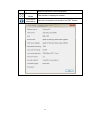
User Manual for DOP-W Series
DOP-W Series have 3 Models type with DOP-W105B, DOP-W127B and
DOP-W157B.
Before introduce function of DOP-W series, there is something to describe how
to enter system menu and how to download the screen data to HMI.
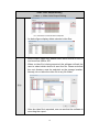
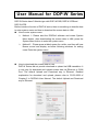
How to enter system menu
Method 1、Please start the DOPSoft software and create System
Menu button, after downloading the screen data to HMI, press the
System Menu button to enter the system menu.
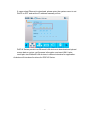
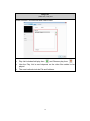
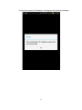
Method 2、Please press at blank space for a while, and then will hear
Buzzer sound and display as below following windows for asking
users Enter the system menu.
How to download the screen data to HMI
DOP-W Series did not provide download or upload via USB translation. It
is only way for download and upload screen data via Ethernet or COM
Port. The default Upload and Download way is Ethernet. Detailed
explanation for download and upload, please refer to P.252~2509 of
Chapter 2 in DOPSoft User Manual. The default Upload and Download
way is Ethernet.
1
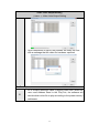
If users select Ethernet to download, please enter the system menu to set
DHCP to OFF and set the IP address manually at first.
DOP-W Series provide two Ethernet LAN devices to download and upload
screen data or recipe, get firmware information and reset HMI. It also
could plan two Ethernet LAN devices in different domains for application.
As below will introduce functions for DOP-W Series.
2
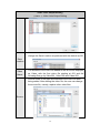
1、Password Setting
Password setting is used to divide user level with HMI. The security level
involved 0 to 7 and has default password in every security level. DOP-W
Series also provide multi-account and password to let several users log in to
HMI.
NOTE:
Password cannot be set as empty.
Please do not set the same account in the same security level, but it could
set the same password in the same security level.
The account could set the same in different security level. For example, if
security level 0 set account to 123, the 123 account also could set in
security level1.
The length limitation for account and password is 24 characters.
The account and password are case insensitive. It will only display the
capital letters.
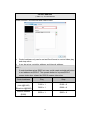
Security Level 0
No protection function is available. Any person can
operate the system.
Security Levels
1~7
Entry of password or override with high permission level
is required to operate the system.
Security Level 8
This is password for the highest permission level and is
higher than those for levels 1 ~ 7. Meanwhile, this
password is the protection password once a project is
saved and is also used for Check password when
download program and system file formatting.
《Table 1-1》Table of permission levels
3
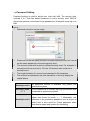
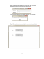
When the user wants to change the password in each level, this can be done
by changing the password entry through [Options] [Password Setting]. The
length limitation for account and password is 24 characters. The entered
password can have up to 8 digits, which consist of numbers of 0 ~ 9 and
alphabets of A ~ F regardless of capitalization or lower-case. The user can
choose the digits and characters of the password as preferred with flexibility.
《Figure 1-1》Password Editing
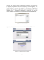
When users set the same account in the same security level, HMI will display Account
Duplicate error message.
《Figure 1-2》Duplicate for Account setting
4
Users also could via Password table setup element to change account and
password.
《Figure 1-3》Password Table Setup button
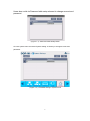
Or enter system menu and select System setting Security to change account and
password.
《Figure 1-4》Password setting in system menu
5
2、Multimedia
DOP-W Series provides multimedia player used to play operation and
maintenance instructions video, so that each operator can have a clear and
straightforward, and thus more effective to reach work; or standard operating
procedures used to play video presentation to help user who establish a good
working environment.
Video can be selected directly or video files you would like to play within the
Word register values to specify a different video files to play
Note:
One screen only could establish one video element.
Sub screen could not establish video element.
Base screen could not establish video element.
Video element did not support rotate function.
The video format only support WMV file.
Video can be described with three major items:
(1) Video Lists Output Setting
(2) Control Address
(3) Play List
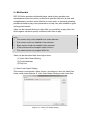
(1) Video Lists Output Setting
This function involves add, delete, export, and where to save the video files.
Users could select Options Video Lists Output Setting to add video files.
《Figure 2-1》Video Lists Output Setting
6
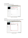
(2) Control Address
It is used to control video play or stop.
Users could select ElementMultimedia to create video.
《Figure 2-2》Control Address
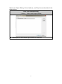
(3) Play List
Play List decides if the video file is to be played through select directly file or
set Word register values to specify a different video files to play.
《Figure 2-3》Play List
7
Video Lists Output Setting, Control address, and Play List are described in the
details below.
Video Lists Output Setting
《Table 2-1》Video
Lists Output Setting
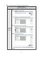
Description of Add, Delete Export button for video file
8
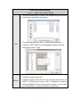
Video Lists Output Setting
《Table 2-1》Video
Add
Delete
Lists Output Setting
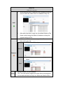
Once the Add button is clicked, the software will ask the user
to select the video file to be played.
The user can add up to 999 (1 ~ 999) video effect files.
If add the 1000th video file, it will display as below following
message to inform users.
Once the video to add is selected, could press Delete button
to delete a certain video file
If delete multiple video files, one can click the video file or use
SHIFT + left button of mouse or Ctrl + left button of mouse to
select multiple file. Once the selection is done, one can click
the Delete button to execute deletion of video files.
9
Video Lists Output Setting
《Table 2-1》Video
Lists Output Setting
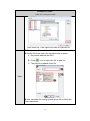
As below figure display delete selected video files.
Before export video files, please select which device to save. It
can be set as USB or SD.
When a video file is being exported, the software will ask the
user to select which device to save the file. Please note that
the root directory must be selected as the storage location.
Namely, do not save the video file in any file folder.
匯出
After the video file is exported, one can see that the software is
executing the export.
10
Video Lists Output Setting
《Table 2-1》Video
Lists Output Setting
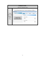
Upon completion of export, the software will notify the user
with a message that the video file has been exported.
Description of Field Name
ID
ID is a major reference value in playing video files. When the
user uses Address Read in the Play List, the software will
decide which video file to play according to the preset memory
addresses.
11
Video Lists Output Setting
《Table 2-1》Video
Lists Output Setting
Available Save Locations are USB and SD. The user can
change the Save Location as preferred with the default as SD.
The filename of the video file added to the list will be displayed
as Video, with the first video file starting at 001 and the
following files go by Video001, Video 002 and Video 003.
Source refers to the path and address of the video file after
being added. After adding the video file, the user can change
the source file, namely, replace other video files.
Save
Location
Video
Name
Source
12
Control Address
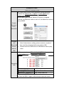
《Table 2-2》Control Address
Select Element multimedia and create video.
Control address only can be set as Word format to control video play
and stop action.
It can be set as controller address and internal address.
Note:
If control addres set as $200, but user could create maintained button
to set address as $200.0. The operate behavior is press $200.0
means video play, relase the $200.0 means video stop.
Control address
Controller address
(Link1@D100)
(EtherLink1@D200)
Internal address
Play
Stop
D100 = 1
D100 = 0
D200 = 1
D200 = 0
$200 = 1
$200 = 0
($200)
13
Play List
《Table 2-3》Play List
Select Element multimedia and create video.
Play List includes Add play item
How the Play List is read depends on the video files added to be
played.
The read methods include File and Address.
14
and Remove play item.
Play List
《Table 2-3》Play List
When Add play item is selected, the software will ask the
user to select the video files to be added to Play List.
After add video item to play list, the default Mode is File.
Users could change the Mode to Address or keep the
original setting as File.
Users could delete unnecessary video file as needed
after add in play list.
Select Video001 and press remove icon。
Add
Before
Remove
After remove Video001 will display as below
figure.
After
Mode
Mode includes File and Address.
File: The user directly selects the video files to be played in
the list and add them to Play List. When the Word or Bit in
15
Play List
《Table 2-3》Play List
Name
Control List is triggered, the selected sound files will be
played.
Address: A certain register address will be designated. When
the trigger condition matches, the number entered into the
register will be read and the corresponding number in [Video
Lists Output Setting] [Video List] to play the associated
sound file.
Address corresponding number, please refer to the example
shown below.
When the written address is 0, the corresponding number 1 to
play the video list; a value of 1, the corresponding list of video
playing number 2, and so on.
Name is defined by the fixed filename video with number
starting at 001. The filenames of the subsequent files follow
16
Play List
《Table 2-3》Play List
by Video002, and Video003, etc.
Repeat
If you check the repeat play, whether the mode is File or
Address, will be on the playlist of video play once, and then
playing from the first list of repeat play until the user stops the
action is triggered to stop playing.
17
The setup example of Video will be described below.
Example of Video
《Table 2-4》Example of Video
Please select Options Video Lists Output Setting and
press add button to select video.
After add video, it will display as below figure.
Please set Save Location as USB.
Video Lists
Output
Setting
Please press Export button.
After execute Export, it will ask users to select storage
device.
18
Example of Video
《Table 2-4》Example of Video
After press OK, it will export the video to USB device.
Please select Element multimedia and establish a video.
Double Click the video and set parameter as below.
A. Set control address as $201.
B. Press
icon to add video file to play list.
C. The play list of added video file.
Video
After complete the setting, please press OK to finish the
Video parameter.
19
Example of Video
《Table 2-4》Example of Video
Create Maintained button and set address as $201.0.
Create
Maintained
Button
(Video
Play)
20
Example of Video
《Table 2-4》Example of Video
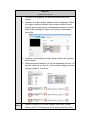
Create three numeric entry elements and set as below
address like {EtherLink2_1}1@D10, {Link2}1@D20 and
{EtherLink2_1}1@D5.
Set Data Type to Word, Memory Format to Unsigned
Decimal, the Minimum value is set as 0, the Maximum value is
set as 65535.
Create
Numeric
Entry
elements
Compile
and
Download
screen
data to
HMI
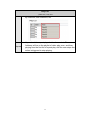
After finished above setting, please execute compile at
first, and then download all screen data to HMI.
Please insert the USB device to HMI before start to play
video.
Please set value as {EtherLink2_1}1@D10 = 2,
{Link2}1@D20 = 6 and {EtherLink2_1}1@D5 = 1.
Operating
HMI
EtherLink2_1}1@D10 = 2
Play History video file
{Link2}1@D20 = 6
Play Tom2 video file
{EtherLink2_1}1@D5 = 1
Play 115200 video file
Press the $201.0, HMI will play the video.
Press the $201.0 again, HMI will stop to play the video.
21
3、VNC
VNC(Virtual Network Computing) is a PC software used to help the
customers view and check the same screen shown on W series of HMI at the
production site, and control the manufacturing process via Ethernet. No matter
where you are, remote controlling is not an arduous task at all.
3.1
Connection introduce for HMI
Create HMI Project File
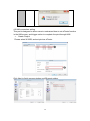
Start DOPSoft software program for w series and click File > New
or click New icon to create a new project. Then, click Element >
Input > Numeric Entry to create two numeric entry elements ($3
and $6) on the screen. In this case, W105B type DOP W series
HMI is used.
Use Screen Cycle Macro and enter the following commands in macro
command window.
22
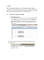
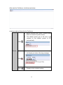
Click Options > Configuration > Network App > LocalHost, check the
Application (Net App VNC) function Enable. Then, press OK button to finish
the settings.
After finishing above setting, please compile and download all screen data
to HMI.
23
3.2
VNC Setting
There are three ways to use VNC Viewer to connect with HMI.
Computer Software
Web Browser
Android App
3.2.1 Computer Software
Software installation
Please following the below URL link to download VNC software which
adapt the operating system.
http://www.realvnc.com/download/vnc/latest/
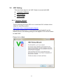
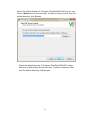
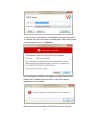
After double clicking VNC-5.2.0-Windows file downloaded from the
website exe file, the following dialog box will appear. Click on Run button
to install VNC.
Please click on Next.
24
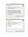
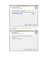
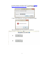
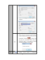
Please choose I accept the agreement, and then click on Next.
Please check all components, and then click on Next.
25
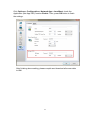
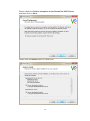
Select the default directory C:\Program Files\RealVNC\VNC Server, and
click on Next button for the next step. To select a directory other than the
default directory, click Browse.
Select the default directory C:\Program Files\RealVNC\VNC Viewer,
and click on Next button for the next step. To select a directory other
than the default directory, click Browse.
26
User could check create a VNC Viewer desktop icon option or not and
then click on Next.
27
Please check the Add an exception to the firewall for VNC Server,
and then click on Next.
Please click on Install button to install VNC.
28
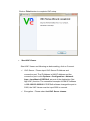
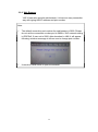
Click on Finish button to complete VNC setup.
Start VNC Viewer
Start VNC Viewer and following as below setting, click on Connect.
VNC Server:Please input VNC Server IP Address and
connection port. The IP Address is HMI IP Address and the
connection port is click Options > Configuration > Network
App > LocalHost of DOPSoft, set port of the Application (Net
App VNC) function. The connection example for HMI IP Address
is 192.168.123.26:5900. If DOPSoft software changed the port to
5902, the VNC Viewer must be input 5902 to connect.
Encryption:Please select Let VNC Server choose.
29
If connection is successfully, it will appear the following window
to remind user this connection is unencrypted. User could ignore
this warning and click on Continue.
But if connection is failed, it will appear the following window. It
means the IP address does not exist or the VNC network
application is not enabling.
After connection successfully, VNC will ask user to input the
30
connection password for HMI and VNC. The password is DOPSoft
Network App password setting of VNC, default is 12345678.
If type incorrect password, it will appear the following message.
After authentication pass, the connection is established.
31
3.2.2 Web Browser
VNC Viewer also provide web browser, it is have an easy connection
way with typing HMI IP address and port number.
Note:
The default connection port number for web browser is 5800. Please
do not set the connection number port to 5800 in VNC network setting
in DOPSoft. If user set to 5800, after download to HMI, it will appear
following as below message to inform user to change port number.
It needs to install JAVA to open the browser.
32
Step1. Open the web browser, for example is using Google Chrome.
Google Chrome browser connection example:
Please type the IP address and port number:
http://192.168.123.48:5800/.
IE browser connection example:
Please type the IP address and port number:
http://192.168.123.26:5800/.
Firefox browser connection example:
If use Firefox browser to connect, please turn off the proxy at first.
Then type the IP address and port number:
http://192.168.123.26:5800/.
If type incorrect IP address, it will not display any content.
After typing the correct IP address, it will appear following as below
window, please click on OK.
33
Step2. Please input the password to connect with HMI, the default
password is 12345678 which set from DOPSoft VNC.
If type incorrect password, it will display as below error message.
Step3. After authenticate successfully, the connection is established.
34
c. Android App
Please get the VNC Viewer App from Google play store at first.
After download, please execute the app to finish the following
steps.
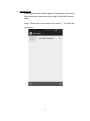
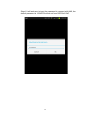
Step1. Please click on the bottom left corner【+】to add new
connection.
35
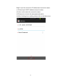
Step2. Input the connection IP address and connection name.
(1) Please input HMI IP address and port number.
(2) User could custom the connection name.
(3) Please do not check the save password option.
(4) After finishing above setting, please click on the below icon.
36
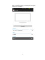
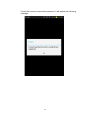
Step3. Complete the setting, it will display as below figure.
Please click on Connect.
37
If input the incorrect IP address, it will appear the following message.
38
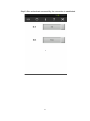
Step4. It will ask user to input the password to connect with HMI, the
default password is 12345678 which set from DOPSoft VNC.
39
If input the incorrect connection password, it will appear the following
message.
40
Step5. After authenticate successfully, the connection is established.
41
3.3
VNC Viewer Detail Setting
After the VNC Viewer connected with HMI, move the mouse to the
upper window, it will appear the tool bar.
The following table will introduce related function.
New
connection
1. Click on
Use new connection could operate multiple HMI.
, it will appear as below window to type another HMI IP
Address for operating.
2. After new connection establishing, the VNC Viewer is connecting with two
HMIs.
42
Save
Connection
1. Click on
The save connection function could save the
configuration for next time connection. User executes
connection without type IP address and password.
, it will appear as below two windows.
43
Please choose Save VNC Server Password in Password Behavior
window, and then click on OK to save connection.
After saving, the configuration is saved as to VNC Address Book.
44
User also saves multiple connections as below figure.
Only start VNC Address Book and select the connected IP address when
next connection.
Close
Connection
Click on
Close connection will close VNC Viewer with HMI
connection
, it will ask users the following question.
Click on Yes, it will close the connection.
Click on No, the connection is still connecting.
Options
Detailed setting for VNC Display, Inputs,
Troubleshooting, and Expert. All of these
configurations is VNC original setting, and use default
parameters to connect with HMI. Therefore, this part
45
does not describe more explanation.
Full Screen
Mode
The function is display full screen.
Connection
Information
Get more connection information for VNC Viewer.
46
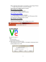
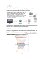
4、e-Printer
ePrinter offer users in HMI without connecting entity end printers can print
directly through the Internet, space-saving and printing hardware devices
convenience. Please refer to as below structure of ePrinter.
e-Printer function could described as two parts. Fisrt is introduce for PrnServer;
Second is how to set HMI connect with ePrinter to print.
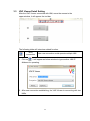
4.1 PrnServer
PrnServer is an execution file, users could start the PrnServer and deliver file
to print through Ethernet.
PrnServer execution file location as below path C:\Program Files (x86)\Delta
Industrial Automation\DOPSoft 2.00.01\PrnServer.exe.
47
After start the PrnServer, it will show as below.
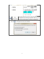
As below table will describe for PrnServer.
Before execute print action, please press
Start to connect to printer server.
The default printer port is 85 and it will
connect to the default printer of PC
automatically.
Start
Printer
Press Stop to disconnect the connection, it
will display as below following message.
Display printer detailed setting.
Stop
Setting
48
Users could change the wanted printer to
connect.
Press Exit will close the PrnServer.
When users do not seed to use PrnServer
to print, please press Exit to disconnect the
connection. If press
not stop the connection. When start the
PrnServer again, it will display as below
following message to inform users.
Exit
Help
About
to close, it will
Display current
49
version of
PrnServer.
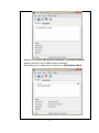
4.2 HMI connection setting
This part is designed to allow users to understand how to set ePrinter function
in the HMI screen, and trigger action to complete the print through HMI.
Create Project
Please select W105B, and set print as ePrinter.
Click Next to finish communication and Ethernet setting.
50
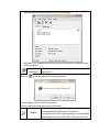
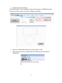
Printer setting
Select Options ConfigurationsPrint and choose Ethernet at Interface, fill
IP address and printer port.
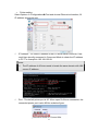
IP Address:It is filled IP address of the PC which starts PrnServer. User
could type ipconfig command in Command Mode to check the IP address
in PC. For example is 192.168.123.68.
Note:
The IP address of ePrinter needs to locate the same domain with HMI
screen IP address.
Port:The default printer port is 85. When open PrnServer connection, the
connected printer port is also 85 like as below figure.
51
Create Report List element
Create Rectangle, Circle and Report List button elements in DOPSoft screen,
and then set report device to Printer in Report List button.
Execute compile and download all screen data to HMI.
After press print button, please start the PrnServer and click start to
connection.
52