1
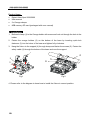
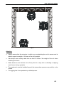
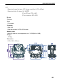
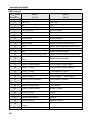
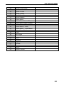
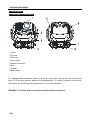
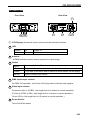
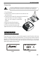
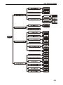
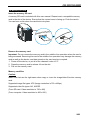
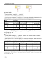
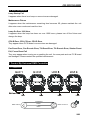
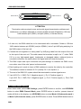
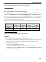
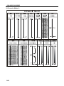
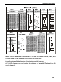
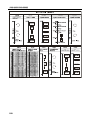
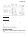
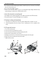
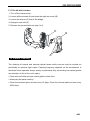
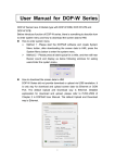
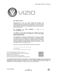
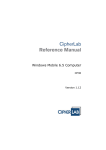
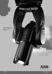
DigiVideo Spot DVS-2500/DVS-5000/DVS-5000II User Guide Please read these instructions carefully before use DVS-2500/5000/5000II 1B DVS-2500/5000/5000II CONTENTS 1. Safety Instruction ............................................................................................................... 3 2. Installation ................................................................................................................................ 5 3. Technical Specification .................................................................................................. 7 4. Description ............................................................................................................................11 4.1 Description of the fixture ..................................................................... 11 4.2 Control Panel ..................................................................................... 12 5. Lamp .......................................................................................................................................... 13 6. How To Set The Unit ...................................................................................................... 14 6.1 Display Status When Power On......................................................... 14 6.2 Main Function .................................................................................... 15 6.3. Home Position Adjustment ............................................................... 25 6.4. Memory card ..................................................................................... 26 6.5. Error Information ............................................................................... 28 7. Control By Universal DMX Controller............................................................... 28 7.1 Connection ........................................................................................ 28 7.2 Channel Mode Setting ....................................................................... 29 7.3 Address Setting ................................................................................. 30 7.4 DMX 512 Configuration ..................................................................... 30 8. Update Software................................................................................................................ 38 9. Troubleshooting................................................................................................................ 38 10. Fixture Cleaning ............................................................................................................. 40 2B DVS-2500/5000/5000II 1. Safety Instruction WARNIN Please read carefully the instruction manual which includes important information about the installation usage and maintenance. G Please keep this User Manual for future consultation. If you sell the unit to another user, be sure that they also receive this instruction manual. Important: Damages caused by the disregard of this user manual are not subject to warranty. The dealer will not accept liability for any resulting defects or problems. Unpack and check carefully that there is no transportation damage before using the unit. The unit is for indoor use only. Use only in a dry location. Do install and operate by qualified operator. Do not allow children to operate the fixture. Use safety chain when fixing the unit. Handle the unit only by carrying its base instead of head . The unit must be installed in a location with adequate ventilation, at least 50cm from adjacent surfaces. Be sure that no ventilation slots are blocked, otherwise the unit will be overheated. Before operating, ensure that the voltage and frequency of power supply matches the power requirements of the unit. It’s important to ground the yellow/green conductor to earth in order to avoid electric shock. Don’t connect the device to any dimmer pack. During initial start-up, some smoke or smell may arise. This is a normal process and does not necessarily mean that the device is defective, and it will decrease gradually within 15 minutes. Make sure there are no flammable materials close to the unit while operating to avoid fire hazard. Examine the power wires carefully; replace them immediately if there is any damage. Unit’s surface temperature may reach up to 85℃. Don’t touch the housing bare-handed during its operation, and allow about 15 minutes for cooling the unit down before 3B DVS-2500/5000/5000II replacing bulb or maintenance as it could be very hot. Avoid any inflammable liquids, water or metal objects entering the unit. Once it happens, cut off the mains power immediately. Do not operate in dirty or dusty environment; do clean the fixture regularly. Do not touch any wire during operation as there might be a hazard of electric shock. Avoid power wires and other cables twisted. The minimum distance between light output and the illuminated surface must be more than 2.5 meters. Disconnect mains power before fuse/lamp replacement or servicing. Replace fuse/lamp only with the same type. In the event of serious operating problem, stop using the unit immediately. Never turn on and off the unit time after time. The housing, the lenses, or the ultraviolet filter must be replaced if they are visibly damaged. Do not open the unit as there are no user serviceable parts inside. Never try to repair the unit by yourself. Repairs carried out by unskilled people can lead to damage or malfunction. Please contact the nearest authorized technical assistance center if needed. Disconnect the mains power if the fixture has not been used for a long time. Do use the original packing materials before transporting it once again. Caution To prevent or reduce the risk of electrical shock or fire, do not expose the unit to rain or moisture. Hot lamp explosion hazard. Do not open the unit within 15 minutes after switching off. Do replace the bulb once it is damaged, deformed or life-expired. Do not look directly at the light while the bulb is on. Never touch bulb with bare fingers, as it is very hot after using. Do not start on the unit without bulb enclosure or when housing is damaged. WARNING! Maximum ambient temperature TA: 40℃. Don’t operate it when the temperature is higher. 4B DVS-2500/5000/5000II Product Items Digital Video Spot 2500/5000 User manual 2 x Omega clamps 8GB memory SD card (packaged with user manual) 2. Installation 1. Bolt each clamp (1) to the Omega holder with screw and lock nut through the hole in the holder. 2. Fasten the omega holders (2) on the bottom of the base by inserting quick-lock fasteners (3) into the holes of the base and tighten fully clockwise. 3. Hang the fixture to the support (4) through clamp and fasten the screws (5). Fasten the safety cable (6) through the bottom of the base and over the support. 1 4 2 6 3 5 90° Fig.1 Fig.2 4. Please refer to the diagram to know how to install the fixture in correct position. 5B DVS-2500/5000/5000II Fig.3 Attention: Always ensure that the structure to which you are attaching the unit is secure and is able to support a weight of 10 times of the unit’s weight. Also always use a safety cable that can hold 12 times of the weight of the unit when installing the fixture. Make absolute sure that the unit is firmly fixed in a way that no vibrating or slipping would occur during operation. The equipment must be installed beyond the areas where persons may walk by or be seated. The rigging has to be operated by a skilled person. 6B DVS-2500/5000/5000II 3. Technical Specification Power supply - AC 120V~240V 50/60Hz Power Consumption - 250W at 230V 50Hz (DVS 2500) - 260W at 120V 60Hz (DVS 2500) - 370W at 230V 50Hz (DVS 5000) - 373W at 120V 60Hz (DVS 5000) Fuse - T 6.3 A Projector - Beam angle: 24 degree (DVS-2500); 30 degree (DVS-5000) - Light output(ANSI Lumens):2500(DVS-2500); 3600(DVS-5000) - Contrast Ratio (Typical Full on/ Full off): 1800:1(DVS-2500); 2600:1(DVS-5000) - Display technology: DLP by Texas Instruments - Lamp: Osram E20.8 180W (DVS-2500) , HRI 280W (DVS-5000)Lamp - Lamp life time: 1,000 hrs (In the moving head) - Resolution: SVGA 800 x 600 - Built-in Image/Video size: 720 x 480 Wireless control - Wirelessly controlled by W-DMX (option). - Each W-DMX is sending out 512 channels of DMX. - License free band of 2.45 GHz Movement - Pan: 540° - Tilt: 270° - Pan/Tilt moving speed adjustable. - Automatic Pan/Tilt position correction. - Built-in Pan/Tilt macro effects - Easy calibration and maintenance by magnetic home positioning. - Pan/Tilt position lock for transporting protection. Image/ Video inputs: - Data projector: 1x15-pin VGA port, 1xS-Video (NTSC or PAL) port, 1xComposite (CVBS) 7B DVS-2500/5000/5000II port - Supported image file types: JPG (Image resolution is 720 x 480px) - Supported video file types: AVI, MJPEG (From SD card: 720 x 480) (From computer: 800 x 600 ) Shutter - Blackout Cool - Fan cooled Protocols - DMX 512 - Date input/output: 3/5 Pin XLR socket Memory card - Memory card slot, hot swappable, max. 32 GB (Built in 8GB) Weight - 17.5kgs Dimension - 550 × 296 × 518 mm 8B DVS-2500/5000/5000II DMX Channels Mode Channel Mode 2 29-CH 1 Pan Pan 2 Pan Fine Pan Fine 3 Tilt Tilt 4 Tilt Fine Tilt Fine 5 Pan/Tilt Speed Pan/Tilt Speed 6 Pan/Tilt Macro Shutter 7 Shutter Picture/Video 8 Picture/Video Video Number 9 Video Number Video Speed 10 Video Speed Layer1 Picture Directory /Color 11 Red Layer1 Picture Number/Preset Color 12 Green Layer2 Picture Directory 13 Blue Layer2 Picture Number 14 Layer1 Picture Directory /Color Layer3 Picture Directory/Filter Picture 15 9B Mode 1 54-CH Layer1 Picture Number/Preset Color Layer3 Picture Number 16 Layer1 Center Offset Picture Macro 17 Layer1 Center Rotation Picture Macro Center Offset 18 Layer1 X Zoom Picture Macro Center Rotation 19 Layer1 Y Zoom Picture Macro X Zoom 20 Layer1 Zoom Macro Picture Macro Y Zoom 21 Layer1 Rotation Picture Macro 22 Layer2 Picture Directory Picture Macro Rotation 23 Layer2 Picture Number Focus 24 Layer2 Center Offset Color mode 25 Layer2 Center Rotation Screen Format 26 Layer2 X Zoom Mirror 27 Layer2 Y Zoom Keystone 28 Layer2 Zoom Macro Source 29 Layer2 Rotation Special Function 30 Layer3 Picture Directory/Filter Picture 31 Layer3 Picture Number Zoom Macro DVS-2500/5000/5000II 32 Layer3 Center Offset 33 Layer3 Center Rotation 34 Layer3 X Zoom 35 Layer3 Y Zoom 36 Layer3 Zoom Macro 37 Layer3 Rotation 38 Picture Macro 39 Picture Macro Center Offset 40 Picture Macro Center Rotation 41 Picture Macro X Zoom 42 Picture Macro Y Zoom 43 Picture Macro 44 Picture Macro Rotation 45 Focus 46 Color mode 47 Screen Format 48 Mirror 49 Keystone 50 Brightness 51 Contrast 52 Freeze 53 Source 54 Special Function Zoom Macro 10B DVS-2500/5000/5000II 4. Description 4.1 Description of the fixture 1. Head 2. Tilt lock 3. Pan lock 4. Front panel 5. Memory card slot 6. Arm 7. Handle 8. Back panel For transportation protection, please set the tilt lock/unlock (2) and the pan lock/unlock lever (3) in the lock position before any transportations. To unlock the head, move the tilt lock/unlock (2) and the pan lock/unlock lever (3) to unlock position. Caution: The head and arm must be unlocked before operation! 11B DVS-2500/5000/5000II 4.2 Control Panel Front View Rear View 9 3 2 1 4 5 6 1 ○ LCD Display: shows the various menus and the selected functions. 2 ○ LED 3 ○ POWER On Power on DMX On DMX input present 7 8 Antenna W-DMX wireless receiver receive signal from a wide range. 4 ○ 5 ○ Button MENU Used to select the different menu items UP To go up in the menu and to increase the values shown on the display DOWN To go back in the menu and to lower the values shown on the display ENTER Used to confirm your choice. DMX input/output sockets: For DMX 512 operation, use 3/5-pin XLR plug cable to link the units together 6 ○ Video input sockets: Composite video in (CVBS): (the length limit to 3 meters in normal operation.) S-Video in (NTSC or PAL): (the length limit to 3 meters in normal operation.) 15-pin VGA in: (the length limit to 10 meters in normal operation.) 7 ○ Power Switch: Turns On/Off the power 12B DVS-2500/5000/5000II 8 ○ Power Cable: To connect to the mains AC outlet 9 ○ Fuse (T 6.3 A): Protect the unit from damage of over current. 5. Lamp Osram E20.8 180W or HRI 280W Lamp Because of its high internal pressure, there might be a risk that the discharge lamp would explode during operation. The lamp emits intense UV radiation which is harmful to the eyes and skin. The high luminance of the arc can cause severe damage to the retina if you take a close look at the lamp. To protect the lamp, always turn off the lamp first (via control panel or DMX controller) and let the unit’s fan run at least five minutes to cool down before switching off the mains supply. Never handle the lamp or luminarie when it is hot. Do not touch the bulb with bare hands. If this happens, clean the lamp with denatured alcohol and wipe it with a lint free cloth before installation. The lamp generates UV radiation. Never operate the lamp without appropriate shielding. When lighting up, the lamp operates at high pressure and there is a slight risk of arc tube rupture. The risk increases with age, temperature and improper handling of the lamp. Do not use the lamp longer than its lifespan. 13B Make sure the lamp is located in the right position of the unit for the best projection. DVS-2500/5000/5000II Change Lamp WARNING In case of replacement of the lamp or maintenance, do not open the fixture within 15 minutes until the unit cools down after switching off. 1. Turn off the power. 2. Unscrew the four screws (A), open the cover, and move it as the sketch shown. 3. Unscrew the two screws (B), hold and pull the handle (C) to remove the lamp. (If you want to change a lamp, you must change the lamp-socket together) 4. Inset a new lamp follow the groove. 5. Tighten the screws (B) to fix the lamp. 6. Put the cover back to the device and Tighten the screws (A) to finish changing lamp. 6. How To Set The Unit 6.1 Display Status When Power On Every time you turn on the unit, it will run built-in program to reset all motors to their home position, the display will show as fig.4(DVS-2500), you may hear some noises for about 20 seconds. It will show warning sign if it goes wrong during resetting and you can press the MENU button to view the error information. After that the unit will be ready to receive DMX signal and the display will show as fig.5. DVS-2500 Fig.4 Fig.5 14B DVS-2500/5000/5000II Explanation of fig.5: Base 30°C 001 Md.1 54Ch Present temperature of base CPU is 30°C Present DMX start address Present channel mode is mode 1 (54 channels mode) Warning signal blinking indicates resetting error, press Enter for more details. 6.2 Main Function Turn on the unit, press MENU button into menu mode, press UP and DOWN button until the required function is shown on the monitor. Select the function by ENTER button. Use UP and DOWN button to choose the submenu, press the ENTER button to store and automatically return to the last menu. Press MENU button or let the unit idle one minute to exit menu mode. The main functions are shown below: 15B DVS-2500/5000/5000II 16B DVS-2500/5000/5000II DMX Settings Enter menu mode, select DMX Settings, press ENTER button to confirm, press UP/DOWN button to select DMX Address, DMX Channel Mode, View DMX Value or WDMX Setting DMX Address—DMX512 address setting Select DMX Address, press ENTER button to confirm, the present address will blink on the display, press UP/DOWN button to adjust the address from 1 to 512, press ENTER button to store. Press MENU button back to the last menu or let the unit idle one minute to exit menu mode. 17B DVS-2500/5000/5000II DMX Channel Mode—channel mode Select DMX Channel Mode, press ENTER button to confirm, present channel mode will blink on the display, press UP/DOWN button to select Mode1 (54 channels mode) or Mode 2 (29 channels mode), press ENTER button to store. Press MENU button back to the last menu or let the unit idle one minute to exit menu mode. View DMX Value Select View DMX Value, press ENTER button to confirm. Channel function and its value will show on the display, press UP/DOWN button to view other DMX value. Press MENU button back to the last menu or let the unit idle one minute to exit menu mode. WDMX Setting—wireless control setting Select WDMX Setting, press ENTER button to confirm. Press UP/DOWN button to select Active, Retransmit or Reset Memory, press ENTER button to store. Press MENU button back to the last menu or let the unit idle one minute to exit menu mode. Active Select Active, press ENTER button to confirm, press UP/DOWN button to select Yes (wireless control available) or No (wireless control unavailable), press ENTER button to store. Press MENU button back to the last menu or let the unit idle one minute to exit menu mode. (Set wireless control to be available, the power indicate LED will blink) Retransmit Select Retransmit, press ENTER button to confirm, press UP/DOWN button to select Yes (Retransmit DMX signal to the next units in the same line) or No (No Retransmit), press ENTER button to store. Press MENU button back to the last menu or let the unit idle one minute to exit menu mode. Reset Memory Select Reset Memory, press ENTER button to confirm, press UP/DOWN button to select Yes (Clear original learning code, and save the new learning code.) or No (No Reset), press ENTER button to store. Press MENU button back to the last menu or let the unit idle one minute to exit menu mode. 18B DVS-2500/5000/5000II Standby Settings Enter menu mode, select Stand Settings, press ENTER button to confirm, press UP/DOWN button to select Standby Mode or Eidt Standby Scene, press ENTER button to store. Press MENU button back to the last menu or let the unit idle one minute to exit menu mode. Standby Mode Select Standby Mode, press ENTER button to confirm, press UP/DOWN button to select Keep (When the DMX signal is cut off, the fixture will remain on its last status.) or Scene (You can edit your own scene for the Standby Mode, when the DMX signal is off, the fixture will remain on the scene that you edited), and press ENTER button to store. Press MENU button back to the last menu or let the unit idle one minute to exit menu mode. Fixture Settings Enter menu mode, select Fixture Settings, press ENTER button to confirm, press UP/DOWN button to select Pan Inverse, Tilt Inverse, BL.O. P/T Moving, or Image Auto Inverse. Pan Inverse Select Pan Inverse, press ENTER button to confirm, present mode will blink on the display, press UP/DOWN button to select No (normal) or Yes (pan inverse), press ENTER button to store. Press MENU button back to the last menu or let the unit idle one minute to exit menu mode. Tilt Inverse Select Tilt Inverse, press ENTER button to confirm, present mode will blink on the display, press UP/DOWN button to select No (normal) or Yes (tilt inverse), press ENTER button to store. Press MENU button back to the last menu or let the unit idle one minute to exit menu mode. P/T Feedback — pan/tilt Feedback Select P/T Feedback, press ENTER button to confirm, present mode will blink on the display, press UP/DOWN button to select No (Pan or tilt’s position will not feedback while out of step.) or Yes (Feedback while pan/tilt out of step. ), press ENTER button to store. Press MENU button back to the last menu or let the unit idle one minute to exit 19B DVS-2500/5000/5000II menu mode. BL.O. P/T Moving—Blackout while pan/tilt moving Select BL.O. P/T Moving, press ENTER button to confirm, present mode will blink on the display, press UP/DOWN button to select No (normal while pan/tilt moving) or Yes (blackout while pan/tilt moving), press ENTER button to store. Press MENU button back to the last menu or let the unit idle one minute to exit menu mode. Sw. Source Delay—Delay while switch the sources Select Sw. Source Delay, press ENTER button to confirm, present mode will blink on the display, press UP/DOWN button to select from 0s (No delay) to 60s (Delay 60 seconds to show the new source output while switching sources.), press ENTER button to store. Press MENU button back to the last menu or let the unit idle one minute to exit menu mode. Image Auto Inverse Select Image Auto Inverse, press ENTER button to confirm, present mode will blink on the display, press UP/DOWN button to select No (normal) or Yes (Image auto inverse while the DMX value of tilt is over 128 ), press ENTER button to store. Press MENU button back to the last menu or let the unit idle one minute to exit menu mode. Lamp Setting Attention: The lamp will not be on until detected temperature is lower than 45°C. Enter menu mode, select Lamp Setting, press ENTER button to confirm, press UP/DOWN button to select On/Off, State/Power on, Off Via Dmx, On if Dmx on, Off if Dmx off, or Ignition Delay.. On/Off—Turn on/off the lamp Select On/Off, press ENTER button to confirm, present mode will blink on the display, press UP/DOWN button to select On (lamp on) or Off (lamp off), press ENTER button to store. Press MENU button back to the last menu or let the unit idle one minute to exit menu mode. State/Power On—Lamp state while power on Select State/Power On, press ENTER button to confirm, present mode will blink on the display, press UP/DOWN button to select On (Lamp on while power on) or Off (Lamp 20B DVS-2500/5000/5000II off while power on), press ENTER button to store. Press MENU button back to the last menu or let the unit idle one minute to exit menu mode. Off Via Dmx—Turn off the unit via Dmx controller Select Off Via Dmx, press ENTER button to confirm, present mode will blink on the display, press UP/DOWN button to select Yes (Enable the function of turning off the unit via Dmx controller) or No (Disable the function of turning off the unit via Dmx controller), press ENTER button to store. Press MENU button back to the last menu or let the unit idle one minute to exit menu mode. (When you operate the unit via DMX controller, set the value of channel “special function” to “lamp off”, waiting for 8 seconds, then the lamp will be off if you choose “yes” mode). On If DMX On— Lamp turns on when DMX signal is detected Select On If Dmx On, press ENTER button to confirm, present mode will blink on the display, press UP/DOWN button to select Yes (Lamp turns on when DMX signal is detected) or No (Lamp off when DMX signal is detected), press ENTER button to store. Press MENU button back to the last menu or let the unit idle one minute to exit menu mode (If the lamp is off via DMX signal, you can reconnect the DMX controller to make the lamp on). Off If DMX Off— Lamp turns off when DMX signal is cut off Select Off If Dmx Off, press ENTER button to confirm, present mode will blink on the display, press UP/DOWN button to select Yes (Lamp turns off when DMX signal is cut off) or No (Normal), press ENTER button to store. Press MENU button back to the last menu or let the unit idle one minute to exit menu mode. Ignition Delay—Delay time between power on and lamp on Select Ignition Delay, press ENTER button to confirm, present mode will blink on the display, press UP/DOWN button to adjust the delay time from 0S to 255S, press ENTER button to store. Press MENU button back to the last menu or let the unit idle one minute to exit menu mode. Display Setting Enter menu mode, select Display Setting, press ENTER button to confirm, press UP/DOWN button to select Display Direction, Backlight Auto Off, Backlight 21B DVS-2500/5000/5000II Intensity or Temperature unit. Display Direction Select Display Direction, press ENTER button to confirm, present mode will blink on the display, press UP/DOWN button to select Normal, Inverse or Auto(Adjust automatically display direction) press ENTER button to store. Press MENU button back to the last menu or let the unit idle one minute to exit menu mode. Backlight Auto Off Select Backlight Auto Off, press ENTER button to confirm, present mode will blink on the display, press UP/DOWN button to select No (display always on) or Yes (display goes off one minute after exiting menu mode), press ENTER button to store. Press MENU button back to the last menu or let the unit idle one minute to exit menu mode. Backlight Intensity Select Backlight Intensity, press ENTER button to confirm, present mode will blink on the display, press UP/DOWN button to adjust backlight intensity from 1 (darkest) to 10 (brightest), press ENTER button to store. Press MENU button back to the last menu or let the unit idle one minute to exit menu mode. Temperature Unit Select Temperature Unit, press ENTER button to confirm, present mode will blink on the display, press UP/DOWN button to select ℃ or ℉, press ENTER button to store. Press MENU button back to the last menu or let the unit idle one minute to exit menu mode. Fixture Test Enter menu mode, select Fixture Test, press ENTER button to confirm, press UP/DOWN button to select Auto Test or Manual Test Auto Test Select Auto Test, press ENTER button to confirm, the unit will run built-in programs to automatically test pan, tilt, shutter, focus. Press MENU button back to the last menu or exit menu mode after auto test. Manual Test Select Manual Test, press ENTER button to confirm, the present channel will show on the display, press UP/DOWN button to select channel, press ENTER button to confirm, 22B DVS-2500/5000/5000II then press UP/DOWN button to adjust the value, press ENTER button to store, the fixture will run as the channel value selected. Press MENU button back to the last menu or exit menu mode let the unit idle one minute. (All channels value will become 0 after exiting Manual Test menu) Fixture Information Enter menu mode, select Fixture Information, press ENTER button to confirm, press UP/DOWN button to select Fixture Use Time, Lamp On Time or Firmware Version. Fixture Use Time Select Fixture Use Time, press ENTER button to confirm, fixture used time will show on the display, press MENU button to exit. Lamp On Time Select Lamp On Time, press ENTER button to confirm, lamp on time will show on the display, press ENTER button to confirm, press UP/DOWN button to select Exit or Reset Time, press ENTER button to confirm. Press MENU button back to the last menu or exit menu mode let the unit idle one minute. Exit Select Exit, press ENTER button will back to the last menu or exit menu mode let the unit idle one minute. Reset Time Select Reset Time, press ENTER button to confirm, and the lamp on time will clear to 0. Firmware Version Select Firmware Version, press ENTER button to confirm, firmware version will show on the display, press MENU button back to exit. Reset Functions Enter menu mode, select Reset Functions, press ENTER button to confirm, press UP/DOWN button to select Pan&Tilt,, Shutter, Focus, or All. Pan/Tilt—Reset Pan/Tilt Select Pan/Tilt, press ENTER button to confirm, press UP/DOWN button to select Yes (the unit will reset pan and tilt to their home positions) or No, press ENTER button to 23B DVS-2500/5000/5000II store. Press MENU button back to the last menu or let the unit idle one minute to exit menu mode. Shutter—Reset Shutter Select Shutter, press ENTER button to confirm, press UP/DOWN button to select Yes (the unit will run built-in program to reset shutter to its home positions) or No, press ENTER button to store. Press MENU button to exit. Focus—Reset Focus Select Focus, press ENTER button to confirm, press UP/DOWN button to select Yes (the unit will run built-in program to reset Focus to home positions) or No, press ENTER button to store. Press MENU button to exit. All—Reset All Select All, press ENTER button to confirm, press UP/DOWN button to select Yes (the unit will run built-in program to reset all motors to their home positions) or No, press ENTER button to store. Press MENU button to exit. Attention: The lamp will not be on until detected temperature is lower than 45°C. Special Functions Enter menu mode, select Special Functions, press ENTER button to confirm, press UP/DOWN button to select Fixture Maintenance or Factory Setting. Fixture Maintenance Select Fixture Maintenance, press ENTER button to confirm, press UP/DOWN button to select Interval or Remain Time. Interval Select Interval, press ENTER button to confirm, the interval time will show on the display. Press MENU button to exit. Remain Time Select Remain Time, press ENTER button to confirm, the remaining time will show on the display, press ENTER button to confirm, press UP/DOWN button to select Exit or Reset time, press MENU button to exit. Factory Setting Select Factory Setting, press ENTER button to confirm, press UP/DOWN button to 24B DVS-2500/5000/5000II select Yes (the fixture will reset to factory settings) or No, and press ENTER button to store. Press MENU button to exit. 6.3. Home Position Adjustment Press MENU button into menu mode, then hold ENTER button for about 3 seconds into offset mode to adjust the home position. Select the function by ENTER button. Use UP/DOWN button to choose the submenu, press the ENTER button to store and automatically return to the last menu. Press MENU button to exit. Offset Menu Pan -128~127 Tilt -128~127 Shutter 0~255 Focus 0~255 Pan—pan home position adjust Enter offset mode, Select Pan, press ENTER button to confirm, the present position will blink on the display, use UP/DOWN button to offset the value from -128 to 127, press ENTER button to store. Press MENU button to exit. Tilt—Tilt home position adjust Enter offset mode, Select Tilt, press ENTER button to confirm, the present position will blink on the display, use UP/DOWN button to offset the value from -128 to 127, press ENTER button to store. Press MENU button to exit. Shutter—Shutter home position adjust Enter offset mode, Select Shutter, press ENTER button to confirm, the present position will blink on the display, use UP/DOWN button to offset the value from 0 to 255, press ENTER button to store. Press MENU button to exit. Focus—Focus home position adjust Enter offset mode, Select Focus, press ENTER button to confirm, the present position will blink on the display, use UP/DOWN button to offset the value from 0 to 255, press ENTER button to store. Press MENU button to exit. 25B DVS-2500/5000/5000II 6.4. Memory SD card Insert the memory SD card A memory SD card is included with this user manual. Please insert a compatible memory card in the slot of the device. Ensure that the contact area is facing up. Push the card in. You can hear a click when the card locks into place. Remove the memory card Important: Do not remove the memory card in the middle of an operation when the card is being accessed. Removing the card in the middle of an operation may damage the memory card as well as the device, and data stored on the card may be corrupted. 1. Power off the device, or put all of the channels’ value to “0”. 2. Press the memory card to release it from the slot. 3. Pull out the memory card. Memory card files Caution: Make sure that use the right name when copy or cover the image/video files into memory card. Supported image file types: JPG (Image resolution is 720 x 480px) Supported video file types: AVI, MJPEG (From SD card: Video resolution is 720 x 480) (From computer: Video resolution is 800 x 600) 26B DVS-2500/5000/5000II ① Image Folder - 32 picture folders, “Image000 ……Image031”. - At most it can contain 1024 (32 x 32) pictures. - Each folder can put at most 32 pictures in it. Pictures are changeable; please refer to the following diagram to name your own files if you want to change pictures: Folder File name Image000 I000_000.jpg I000_001.jpg …… I000_031.jpg Image001 I001_000.jpg I001_001.jpg …… I001_031.jpg Image031 I031_000.jpg I031_001.jpg …… I031_031.jpg For example: If you want to replace the picture No.1 in the “Image001” folder, rename your own picture as “ I001_000.jpg ”, then copy it into the “Image001” folder of the memory card to cover the older file. ② Video Folder - 31 video folders, “Video001 ……Video031”. (Notice: The “Video000” folder is useless.) - At most it can contain 992 (31 x 32) videos. - Each folder can put at most 32 videos in it. Videos are changeable; please refer to the following diagram to name your own files if you want to change videos: Folder File name Video001 V001_000.avi V001_001.avi …… V001_031.avi Video002 V002_000.avi V002_001.avi …… V002_031.avi Video031 V031_000.avi V031_001.avi …… V031_031.avi For example: If you want to replace the video No.1 in the “Video001” folder, rename your own picture as “V001_000.avi ”, then copy it into the “Video001” folder of the memory card to cover the older file. 27B DVS-2500/5000/5000II 6.5. Error Information Lamp Startup Fail It appears when there is no lamp or some wires are damaged. Maintenance Fixture It appears when the maintenance remaining time becomes 0S, please maintain the unit after enter menu mode and reset the time. Lamp On Over 1000 Hour It appears when the lamp has been on over 1000 hours, please turn off the fixture and change the lamp. CPU-B Error, CPU-C Error, CPU-D Error They appear when P.C.B board or some wires are damaged. Pan Reset Error, Pan Encode Error, Tilt Reset Error, Tilt Encode Error, Shutter Reset Fail, Focus Reset Fail They may appear when turning on or resetting the unit, for some parts such as P.C.B board are damaged. Please contact the qualified maintenance. 7. Control By Universal DMX Controller 7.1 Connection COMMON 1 DMX INPUT 3 2 DMX + DMX - 2 1 3 2 DMX OUTPUT 3 1 28B DVS-2500/5000/5000II DMX INPUT 2 1 3 4 5 COMMON DMX DMX + Not Used Not Used 2 1 4 5 DMX OUTPUT 3 5 4 3 1 2 ATTENTION Termination reduces signal errors and avoids signal transmission problems and interference. It is always advisable to connect a DMX terminal (Resistance 120 ohm 1/4W between pin2 (DMX-) and pin3 (DMX+) of the last fixture). 1. At last unit, the DMX cable has to be terminated with a terminator. Solder a 120-ohm 1/4W resistor between pin 2(DMX-) and pin 3(DMX+) into a 3-pin XLR-plug and plug it in the DMX-output of the last unit. 2. Connect the unit together in a “daisy chain” by XLR plug cable from the output of the unit to the input of the next unit. The cable cannot be branched or split to a “Y” cable. DMX 512 is a very high-speed signal. Inadequate or damaged cables, soldered joints or corroded connectors can easily distort the signal and shut down the system. 3. The DMX output and input connectors are pass-through to maintain the DMX circuit, even when one of the units’ power is disconnected. 4. Each lighting unit needs to have a DMX address to receive the data by the controller. The address number is between 0-511 (usually 0 & 1 are equal to 1). 5. The end of the DMX 512 system should be terminated to reduce signal errors. 6. 3 pin XLR: Pin 1: GND, Pin 2: Negative signal (-), Pin 3: Positive signal (+) 5 pin XLR: Pin 1: GND, Pin 2: Negative signal (-), Pin 3: Positive signal (+), Pin4, Pin5 not used. 7.2 Channel Mode Setting Enter menu mode, select DMX Settings, press ENTER button to confirm, use UP/DOWN button to select DMX Channel Mode, press ENTER button to confirm, present channel mode will blink on the display, use UP/DOWN button to select Mode1 (54 channels mode ) or Mode 2 (29 channels mode), press ENTER button to store. Press MENU button back to 29B DVS-2500/5000/5000II the last menu or let the unit idle one minute to exit menu mode. 7.3 Address Setting If you use a universal DMX controller to control the units, you have to set DMX address from 1 to 512 so that the units can receive DMX signal. Press MENU button to enter menu mode, select DMX Settings, press ENTER button to confirm, use UP/DOWN button to select DMX Address, press ENTER button to confirm, the present address will blink on the display, use UP/DOWN button to adjust the address from 1 to 512, press ENTER button to store. Press MENU button back to the last menu or let the unit idle one minute to exit menu mode. Please refer to the following diagram to address your DMX512 channel for the first 4 units. Unit 1 Unit 2 Unit 3 Unit 4 Address Address Address Address 54 channels 1 55 109 163 29 channels 1 30 59 88 Channel mode 7.4 DMX 512 Configuration Please refer to below configurations to control the fixtures Attention: 1. The unit will remain the last condition if the DMX signal is cut-off. 2. For the channel function, when you change the value from 0~255 very quickly, keep the value for about 5 seconds, then the corresponding function will take into effect. 3. Total three Layers of images. - Layer one: Works as Background function. - Layer two: Works as Shelter function of the background of layer one. - Layer three: Works as Transparent function. (You can see layer one/two through the black part of picture of layer 3.) 30B DVS-2500/5000/5000II 54 Channels (Mode 1): 31B DVS-2500/5000/5000II Notice: Put the DMX value of CH14 from 0~7 so that the function of CH11, CH12, and CH13 is enable. In the same time 15CH works as Preset Color. Layer 2 works as Shelter function of the background of layer one. 0~7 is OFF (It means you can’t project the pictures in “Image000” Folder of the SD card in Layer 2). 32B DVS-2500/5000/5000II 33B DVS-2500/5000/5000II 1 2 2 3 3 1 2 3 2 1 3 3 2 ①: Layer1 ②: Layer2 ③: Layer3 34B DVS-2500/5000/5000II 35B DVS-2500/5000/5000II 29 Channels (Mode 2): 36B DVS-2500/5000/5000II 1 2 2 3 3 1 2 3 2 1 3 3 2 ①: Layer1 37B ②: Layer2 ③: Layer3 DVS-2500/5000/5000II 8. Update Software Download update file from our web site, follow the user manual of IU-01 to update the fixture via IU-01(not included). 9. Troubleshooting Following are a few common problems that may occur during operation. Here are some suggestions for easy troubleshooting: A. The unit does not work, no light and the fan does not work 1. Check the connected power and mains fuse. 2. Measure the mains voltage on the main connector. 3. Check the power on LED to see if it can be light up or not B. Not responding to DMX controller 1. DMX LED should be on. If not, check DMX connectors, cables to see if they are linked properly. 2. If the DMX LED is on and no response to the channel, check the address settings and DMX polarity. 38B DVS-2500/5000/5000II 3. If you have intermittent DMX signal problems, check the pins on connectors or on PCB of the unit or the previous one. 4. Try to use another DMX controller. 5. Check to see if the DMX cables run near or run alongside to high voltage cables that may cause damage or interference to DMX interface circuit. C. One of the channels is not working well 1. The stepper motor might be damaged or the cable connected to the PCB is broken. 2. The motor’s drive IC on the PCB might be out of condition. D. The lamp is cutting out intermittently 1. The lamp is not working well. Check the mains voltage either too high or too low. 2. Internal temperature may be too high. Check if replacement of fan is needed on the head. E. If The pan belt is broken 1. Turn off the mains power. 2. Loosen the screws (A) open the cover (B). 3. Loosen the screws (D) open the base-housing cover (E). 4. Unplug all the connect wires over the belt. 5. Change a new belt (C), put the belt around the axis gear and motor gear. 6. Plug all the connect wires back that upon the belt. 7. Tighten all the screws. B A D A C 39B A E D DVS-2500/5000/5000II F. If The tilt belt is broken 1. Turn off the mains power. 2. Loosen all the screws (A) and open the right arm cover (B). 3. Loosen the screws (C) that fix the bridge. 4. Change a new belt (D). 5. Reverse the procedures from step 3 to 2. D B C A 10. Fixture Cleaning The cleaning of internal and external optical lenses and/or mirrors must be carried out periodically to optimize light output. Cleaning frequency depends on the environment in which the fixture operates: damp, smoky or particularly dirty surrounding can cause greater accumulation of dirt on the unit’s optics. Clean with soft cloth and use normal glass to clean fluid. Always dry the parts carefully. Clean the external optics at least every 20 days. Clean the internal optics at least every 30/60 days. 40B 41- EC Declaration of Conformity We declare that our products (lighting equipments) comply with the following specification and bears CE mark in accordance with the provision of the Electromagnetic Compatibility (EMC) Directive 2004/108/EC. EN55103-1:1996; EN55103-2:1996; EN61000-3-2:2006 EN61000-3-3:2008 & Harmonized Standard EN 60598-2-17: 1989 +A2: 1991 EN60598-1:2008+A11:2009 Part 1:General requirements and test Following the provisions of the low voltage directive 2006/95/EC Innovation, Quality, Performance 43-