1
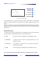
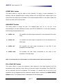
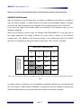
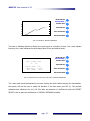
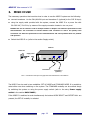
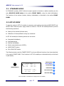
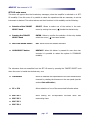
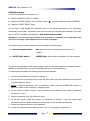
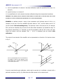
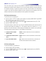
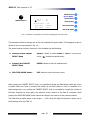
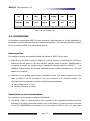
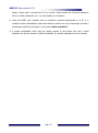
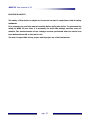
MISO II 2 Channel biomechanical signal amplifier User Manual v1.31 MISO II User manual v1.31 INDEX 1. GENERAL FEATURES ............................................................................................. pag. 3 1.1. GENERAL DESCRIPTION ................................................................. pag. 3 1.2. TECHNICAL SPECIFICATION ........................................................... pag. 3 2. DETAILED DESCRIPTION .................................................................................... pag. 5 2.1. FRONT PANEL ................................................................................... pag. 5 CH1 and CH2 Biofeedback...................................................................... pag. Target ................................................................................................. pag. Overload led ........................................................................................ pag. TARGET SELECT knob ........................................................................... pag. Liquid cristal display and keyboard ......................................................... pag. MODE SELECT button ............................................................................ pag. OFFSET NULL button ............................................................................. pag. GAIN SELECT button ............................................................................. pag. FULL-SCALE REC button......................................................................... pag. RELATIVE MODE button ......................................................................... pag. 5 6 6 6 6 7 8 8 8 9 2.2. BACK PANEL ....................................................................................... pag. 11 Power supply socket .............................................................................. pag. Power supply switch .............................................................................. pag. Fuse box ............................................................................................... pag. RS232 connector ................................................................................... pag. EXT. BIOFEEDBACK connector ............................................................... pag. CH1/AUX IN and CH2 IN connector ........................................................ pag. CH1 OUT, CH2 OUT, CH1+CH2 OUT connector ....................................... pag. Gain adjust ........................................................................................... pag. 11 11 12 12 12 12 13 13 3. MISO II USE .......................................................................................................... pag. 14 3.1. STANDARD MODE .............................................................................. pag. 15 3.2. SET-UP MODE ..................................................................................... pag. 15 SET-UP menu ........................................................................................ pag. Calibration menu ................................................................................... pag. Full-scale select menu ............................................................................ pag. Full-scale edit menu ............................................................................... pag. 16 17 19 20 3.3. ACCESSOIRES ................................................................................... pag. 21 Data acquisition..................................................................................... pag. 21 External biofeedback visualization........................................................... pag. 21 pag. 2 MISO II User manual v1.31 1. GENERAL FEATURES 1.1. GENERAL DESCRIPTION Together with EMG it is often useful to acquire biomechanical variables, for example the contraction level or the movement velocity. The MISO II system has been built to allow acquisition of mechanical variables during a muscular contraction. The MISO II system allows to acquire signals from force, torque, pressure and angular transducers. The signals amplified from the instrumentation can be displayed on a visible multilevel biofeedback or sent to a PC to allow achieving a pre-settable target. 1.1. TECHNICAL SPECIFICATION The biomechanical signal amplifier MISO II can accept signals generated from differential transducers (like strain gauges or load cells) and from single-ended output transducers (like potentiometric transducers). This amplifier can be used in two modalities, absolute and relative. It is also possible, using a display, to select the full-scale of the used transducer and calibrate the system accordingly to any kind of sensors. In absolute mode this instrumentation returns directly the measured physical quantity in the sensor unit (e.g. Kg, atm, N or Nm). The relative mode allows to make measurements that are expressed as a percentage of the maximal contraction registered as MVC (maximal voluntary contraction). The characteristics of the MISO II system are reported in TAB. 1: Channels 1 e 2 Transducers power supply 5 VDC Bandwidth 0 ÷ 60 Hz, low pass Bessel filter (V order) Input noise < 0.7 VRMS Signal amplification 100 ÷ 1000 (for each channel)* Maximal linearity error < 1.5% Selectable gains x1, x2, x5, x10 Maximal gain error < 1.5% CMRR >110 dB Differential input impedance > 90 M (0 f 60Hz) Output range 5V Offset compensation 6V software controlled pag. 3 MISO II User manual v1.31 Auxiliary channel Input range 5V Signal amplification 1 Output range 5V * Base gain value adjustable according with the used transducer. This value is multiplied for one of the four available selectable gains. TAB. 1: Amplifier technical specification pag. 4 MISO II User manual v1.31 2. DETAILED DESCRIPTION 2.1. FRONT PANEL FIG. 1 shows indicators, commands and display of the MISO II system: Target Biofeedback CH1 Overload Led TARGET SELECT knob MODE SELECT SET-UP MODE CH1 OFFSET NULL TARGET SELECT TARGET GAIN SELECT CH2 FULL-SCALE REC LISiN BIOENGINEERING CENTER MISO II FORCE-TORQUE-ANGLE AMPLIFIER Biofeedback CH2 RELATIVE MODE Liquid crystal display Keyboard FIG. 1: Front panel of the MISO II amplifier CH1 and CH2 biofeedback Each biofeedback consists of an array of 50 leds. The lighting of each led indicates a biofeedback level. According to the selected modality on the biofeedback it is possible to display: the signal level of the corresponding channel (channel 1 on biofeedback CH1, channel 2 on biofeedback CH2); the signal level of channel 1 on both biofeedback bars; the signal level of the auxiliary channel on both biofeedback bars; the summation of CH1 and CH2 signals on both biofeedback bars; For details see section: Liquid crystal display and Keyboard. NOTE: A constant level could be displayed on the biofeedback bar also without force applied on transducers; this is only offset that can be eliminated by pressing OFFSET NULL. pag. 5 MISO II User manual v1.31 Target The target bar consists of an array of 50 leds. It is possible to switch on the target led using the TARGET SELECT knob. When the MISO II system is on, at the beginning the target led is off; rotating the TARGET SELECT knob this function is enabled. Each step of the knob corresponds to an increase or a decrease of the target level. This amplifier can be used to reach and maintain a constant level of contraction. During the full scale recording (see FULL-SCALE REC button), the target keep the maximum value reached from the biofeedback CH1. This function can be used to visualize the maximum obtained value in the previous recording and ask the subject to exceed this value. NOTE: The target level can range from 1 (2% F.S.) to 50 (100% F.S.), nevertheless it is better not to ask the subject to make maximal contraction lower than 20% of the full scale range; it is suggested to increase the gain and repeat the contraction again in order to have higher resolution for low targets. OVERLOAD leds These indicators show when the amplitude of the biofeedback signal exceeds the full scale value. The leds switch on with emission of a sound from a buzzer. NOTE: When you are working in absolute mode and the instrumentation full scale is the same as target of the transducers, the switching of the overload leds and of the buzzer indicate that the transducers are working out of their working range and could be damaged. TARGET SELECT knob In STANDARD MODE rotating this knob it is possible to activate the target and to select a level. The knob pressure allow to set a full scale value. To set a full scale value it is necessary to press the TARGET SELECT knob and then rotate it to obtain the desired value. Press the knob again to store the value or press the RELATIVE MODE button to abort the operation. In SET-UP modality the knob rotation corresponds to the choice of a particular submenu. The knob pressure is used to enter the submenu and to confirm the selection. For more information about menus go to the SET-UP MODE section. Liquid crystal display and keyboard Display light switches on when the instrumentation is on. After a short presentation the display shows the following instrumentation settings (see FIG. 2). pag. 6 MISO II User manual v1.31 MODE SELECT GAIN = x1 MODE = CH1 SET-UP MODE OFFSET NULL F.S.1 = 134 Nm F.S.2 = 129 Nm GAIN SELECT Relative Mode OFF FULL-SCALE REC RELATIVE MODE FIG. 2: Example of displayed data Pressing the blue button it is possible to change the selection of the amplifier for biomechanical signals. Each button corresponds to a special function; the different settings are showed on the display. NOTE: If you wish to use a PC to acquire signals with the RS232 port please don’t push any button during acquisition. The instrument could be not able to guarantee the sent of data to the PC while performing other operation. MODE SELECT button This button allows to select the configuration of the biomechanical channels and to select what you wish to display on the biofeedback channels. The possible selections are: CH1 Only channel 1 signals are displayed on both biofeedback channels CH1 & CH2 The signals from each channel are displayed separately on the two biofeedback channels CH1 + CH2 The summation of the signals from the two channels is displayed on both biofeedback channels AUX Only the auxiliary signal is displayed on both biofeedback channels NOTE: The analog signal on the back panel BNCs is independent of the MODE SELECT button selection. pag. 7 MISO II User manual v1.31 OFFSET NULL button This button allows to null the offset on both channels. To make a correct cancellation it is necessary that the displayed signal is stable; please push the OFFSET NULL button again if the previous time the offset was not deleted. If the instrumentation MISO II is not able to delete the offset, the buzzer will ring three times. GAIN SELECT button This button allows to change the gain. The available gains are: x1, x2, x5, x10. If the instrumentation has been calibrated correctly (see SET-UP MODALITY) for the used transducer, the following correspondences hold: GAIN = x1 The amplifier full scale range corresponds to the transducer’s full scale range GAIN = x2 The amplifier full scale range corresponds to half the transducer’s full scale range GAIN = x5 The amplifier full scale range corresponds to one fifth of the transducer’s full scale range GAIN = x10 The amplifier full scale range corresponds to one tenth of the transducer’s full scale range NOTE: If you change the gain of the amplifier, you automatically null the offset on both channels. FULL-SCALE REC button This button allows to record the maximum value reached by the signal acquired from the transducers during a period of time. When you push this button, the message “FULL-SCALE REC” and an advancing bar will be displayed. The recording is 5 seconds long. At the end of the acquisition the bar disappears and the maximum reached value is displayed (see MODE SELECT button section). The displayed value is independent of the selected gain. pag. 8 MISO II User manual v1.31 NOTE: If an overload of the biofeedback system occurs during the acquisition, decrease the gain. RELATIVE MODE button After the recording of the full scale value, by pushing the Relative mode button it is possible to enter the relative modality. In relative mode the full scale of the biofeedback system is changed, so that the full scale corresponds to the maximum value recorded during the FULL-SCALE REC. If you push the relative mode button before the recording of the maximum value, an error message is displayed. When you are working in relative mode, the message “RELATIVE MODE OFF” in the lower part of the display disappears. The display indicates the current value in relation to the maximum recorded value. This indication could change according to the selected gain during FULL-SCALE REC and to the selected gain during the relative mode phase. TAB. 2 shows an example. FULL-SCALE REC Selected gain during Selected gain in RELATIVE mode x1 x2 x5 x10 x1 100% 50% 20% 10% x2 200% 100% 40% 20% x5 500% 250% 100% 50% x10 1000% 500% 200% 100% TAB. 2: Full scale range in Relative mode indicated as percentage of Recorded FULL SCALE and as function of selected gains In relative mode it is possible to use a biofeedback visualization different from the described led bar; this modality is called DISPLAY FEEDBACK. Is possible to enter this modality by pressing the RELATIVE MODE button for two seconds after the activation of the relative modality. pag. 9 MISO II User manual v1.31 MODE SELECT Rel. Mode = Esc SET-UP MODE OFFSET NULL GAIN SELECT FULL-SCALE REC RELATIVE MODE FIG. 3: Example of DISPLAY FEEDBACK This kind of feedback allows to display the input signal as a function of time. The x axis indicate the time, the y axes indicates the percentage value of the recorded full scale. MODE SELECT DISPLAY FEEDBACK SET-UP MODE OFFSET NULL Full screen time T = 5s GAIN SELECT Rotate knob = Sel Push knob = Start Rel. Mode = Esc FULL-SCALE REC RELATIVE MODE FIG. 4: Selection menu for the time scale value (DISPLAY FEEDBACK) The x axis scale should be selected by the user rotating the knob. Before starting the visualization, the system will ask the user to select the duration of the time scale (see FIG. 4). The possible selectable time values are 5s, 10s, 15s, 20s. After the selection it is sufficient to push the TARGET SELECT knob to start the visualization in DISPLAY FEEDBACK modality. pag. 10 MISO II User manual v1.31 2.2. BACK PANEL Fig. 5 shows the back panel connectors of the MISO II system. Power supply switch Power supply socket Input Connectors CH1/AUX IN CH2 IN 0 1 RS232 Fuse box EXT. BIOFEEDBACK RS232 EXT. BIOFEEDBACK Connector Connector CH1 OUT CH1 + CH2 OUT Output Connectors CH2 OUT Gain calibration FIG. 5: Back panel of MISO II Power supply socket Connect the power supply cable to this socket. The MISO II system can be supplied with a supply voltage ranging from 90 to 260 VAC, 50÷60 Hz; it is very important that the supply cable includes the earth connector. DANGER: The use of extension cords or multiple sockets or adaptors can affect the performance of the instrumentation. The connection to sockets without earth connection or with a low quality earth connection can affect the performance of the instrumentation and cause potential harm to patients and operators. Power supply switch On the back panel, together with the power supply connector, the power supply switch can be found. To switch the MISO II on, move the power supply switch to position 1; to switch it off, move it again to position 0. For higher safety, the switch interrupts connection to both power conductors. When the system is not used, this switch should be off. pag. 11 MISO II User manual v1.31 Fuse box On the back panel, together with the power supply connector, a box containing the two power supply fuses (one for each cable) can be found. In normal working conditions the two supply fuses must not be interrupted; the interruption of connection in either of them can occur only when the system is damaged; this means that the device could no longer be in compliance with the security standards, even if the fuses have been replaced correctly. DANGER: In case of interruption of one or both fuses, do not replace them by yourself, but immediately contact the Technical Assistance Service of Ottino Biomedica s.n.c. The interruption of the fuses could be caused by an event that could represent a risk for the patient and the operator, and which must be identified before using the instrumentation again. Besides, replacing the fuses with others of different type can be extremely dangerous for the patient and the operator. Always remove the power cable before testing the fuses. RS232 Connector This connector can be used to allow communication between MISO II and a PC. In fact, it is possible to send the samples of the signals on line and in a digital format using this port. A software to use this feature is still not available. EXT. BIOFEEDBACK Connector An optional external biofeedback device can be connected to this DB15 connector by means of a standard PC monitor cable. An external biofeedback can be positioned in front of the patient in particular conditions when the biofeedback display on the frontal panel of MISO II is not visible by the patient. For more information on the biofeedback system please refer to the section Biofeedback CH1 e CH2. CH1/AUX IN and CH2 IN connectors These connectors can be used to connect the transducers which are being used with the MISO II system. Only the CH1/AUX IN connector can be used to connect potentiometric transducers. Both connectors are DIN 5 poles 180°. The possible connections are represented in Fig. 6. pag. 12 MISO II User manual v1.31 -5V 3 GND 2 IN - A B 4 IN + +5V 1 +5V 5 -5V -5V +5V GND SIGNAL A) Footprint of the CH1/AUX IN and CH2 IN connectors, welded side of the external connector B) Connection of a force / torque transducer C) Connection of a C) Connection of a singlegoniometric transducer ended transducer FIG. 6: Connection of the transducers to MISO II CH1 OUT, CH2 OUT, CH1 + CH2 OUT Connectors These BNC connectors provide the analog outputs of MISO II. The signals present on these connectors are not influenced by the modality in which the system is working, thus they are not affected by the relative modality and are independent of the channels selected to be displayed on the biofeedback. The selected gain (x1, x2, x5, x10) and the offset cancellation, instead, do affect these signals. The signals present on these connectors are: CH1 OUT Signal present at the input CH1/AUX IN, amplified and filtered; CH2 OUT Signal present at the input CH2 IN, amplified and filtered; CH1 + CH2 OUT Summation of the signals present at the input CH1/AUX IN and CH2 IN, amplified and filtered. Gain calibration The two holes beside the output connectors on the rear panel allow to reach two trimmers located inside the instrument. By rotating these trimmers using a small screwdriver it is possible to modify the gain of the two channels continuously, and then to calibrate the amplification. To do so, please refer to the section SET-UP Modality. pag. 13 MISO II User manual v1.31 3. MISO II USE The necessary operations that must be done in order to use the MISO II system are the following: connect transducer 1 to the CH1/AUX IN input and transducer 2 (optional) to the CH2 IN input; using the supply cable provided with the system, connect the MISO II to a power line with 90÷260 VAC, 50÷60 Hz, by means of the supply connector located on the rear panel. DANGER The use of extension cords or multiple sockets or adaptors can affect the performance of the instrumentation. The connection to sockets without earth connection or with a low quality earth connection can affect the performance of the instrumentation and cause potential harm for patients and operators. Switch the MISO II on (refer to the section Supply switch) MISO II Power line Supply cable Transducer 1 Transducer 2 (optional) FIG. 7: Connection of the power supply and of the transducers to the MISO II The MISO II can be used in two modalities: SET-UP MODE and STANDARD MODE. It is possible to select either one when switching on the system. The STANDARD modality can be entered simply by switching the system on using the power supply switch (refer to the entry Power supply switch in the section BACK PANEL). If the MISO II is switched on and simultaneously the buttons MODE SELECT and OFFSET NULL are pressed, the SET-UP modality is selected. pag. 14 MISO II User manual v1.31 3.1. STANDARD MODE In STANDARD modality, MISO II allows to acquire signals in absolute or relative modality (see the entry RELATIVE MODE button in the section FRONT PANEL), using the visual biofeedback. The functions of the devices (buttons, display, biofeedback) is described in the section FRONT PANEL. 3.2. SET-UP MODE To start the system in SET-UP modality is necessary push together the buttons MODE SELECT and OFFSET NULL while the power supply switch is turned on. The SET-UP modality allows to perform the following operations: Setting of the desired full-scale value; Calibration of the amplification using any transducer. In SET-UP modality the following devices are not active: Integrated biofeedback; Integrated target; External biofeedback; Serial communication port (RS232); MODE SELECT button; FULL-SCALE REC button. The following buttons and the TARGET SELECT knob have different functions from those described in the section FRONT PANEL. Their functions in SET-UP modality are indicated directly on the liquid crystal display. MODE SELECT TARGET SELECT SET-UP MENU Calibrate Edit FS2 FS = FS1 Edit FS3 Edit FS1 Edit FS4 Rotate knob = Sel Push knob = Enter Rel. Mode = Esc SET-UP MODE OFFSET NULL GAIN SELECT FULL-SCALE REC RELATIVE MODE FIG. 8: Example of visualization on display in SET-UP modality pag. 15 MISO II User manual v1.31 SET-UP main menu This menu will appear after the introductory messages, when the amplifier is switched on in SETUP modality. From this menu it is possible to select the operations that are necessary to set the instrument as desired. The active buttons and their functions in this modality are the following: Rotation of the TARGET SELECT. Allows to select one of the entries in the main SELECT knob menu by moving the cursor ( Pressing the TARGET ENTER. Allows to confirm the selection of the entry beside SELECT knob which the cursor ( RELATIVE MODE button ESC. Allow to exit the selected submenu. GAIN SELECT button RESTART. When this button is pressed for more than two ) beside the desired entry. ) has been located. seconds it is possible to restart the system in STANDARD modality. The submenus that are accessible from the SET-UP menu by pressing the TARGET SELECT knob when the cursor is beside the desired entry are: CALIBRATE Allows to calibrate the amplification of the two biomechanical channels by rotating the trimmers on the rear panel (see the section Gain calibration) FS = FSX Allows selection of one of the memorized full-scale values. EDIT FS 1 Allow EDIT FS 2 memorizing them. EDIT FS 3 EDIT FS 4 editing pag. 16 the correspondent full-scale value and MISO II User manual v1.31 Calibration menu To enter this submenu it is necessary to: Start the MISO II in SET-UP modality; Rotate the TARGET SELECT knob until the cursor ( Press the TARGET SELECT knob. ) is located beside the entry CALIBRATE; On the liquid crystal display the measured value of the signals generated by the transducers connected to the system, expressed in the units and with the full-scale value selected in the main menu in SET-UP modalità (see the section Full-scale selection menu). WARNING: In case one of the input channels is not connected to a transducer, the correspondent value reported on the display could be different from zero and is meaningless. The active buttons and their functions in this modality are the following: RELATIVE MODE button ESC. Allows to exit to the main menu of the SET-UP modality. OFFSET NULL button OFFSET NULL. Allows offset cancellation for both channels. To perform the calibration of the instrumentation with the desired transducer, a reference value is needed (a measured load or pressure depending the kind of used transducer ). To calibrate the instrument the following steps must be followed: 1. connect the transducer to the input of channel 1; 2. be sure that the correct unit and a proper full-scale value have been selected (see the section Full-scale selection menu); 3. before to load the transducer whit the reference value, press the OFFSET NULL button to cancel the offset of the transducer / amplifier group; 4. be sure that the offset is close to zero by looking at the signals on the display; otherwise, repeat step 3 and 4; 5. load the transducer whit the reference value; 6. on the rear panel, rotate the trimmer correspondent to channel 1 (see the section Gain calibration) until the display indicates the same value as the one used as reference. 7. remove the reference value for the transducer 8. in case the displayed value is different from zero, it is necessary to repeat step 3. pag. 17 MISO II User manual v1.31 9. now the amplification for channel 1 has been calibrated; repeat the operations from step 1 on channel 2; 10. repeat from step 1 on channel 2 11. the amplification for both channels has been calibrated using the correspondent transducer. WARNING: The quantity used as reference value should be at least 50% of the full-scale value of the transducer, in order to minimize the quantization error of the instrumentation. EXAMPLE: to calibrate channel 1 using a force transducer with full-scale value of 100 N, it is necessary to set one of the four available full-scale values to “100”, and the relative unit to “N” (see the section Full-scale setting menu). The reference value in this case can be, for example, 80 N, and can be obtained using a mass of 80 N. After offset cancellation (as indicated at step 3 in the previous instructions) it is necessary to load the transducer with the 80 N mass, and then rotate the trimmer until the message “CH1 = 80 N” is displayed (see the section Gain calibration). The output of one channel of the amplifier can be represented as a function of its input as shown in Fig. 9. Output Output A B Absolute value Input Input Input offset Output C FIG. 9: A) Input/output curve of one channel of the amplifier. B) Effect of gain calibration on the input/output curve. C) Effect of offset calibration on the input/output curve. Input It can be noted that the gain calibration, which must be carried out to calibrate a channel with a particular transducer (see Fig. 9), affects also the offset present on the output signal. pag. 18 MISO II User manual v1.31 This is the reason why, at step 8 of the procedure to calibrate a channel, the offset which had already been cancelled could be different from zero once the gain calibration has been performed. It is therefore necessary to repeat the procedure a few times, until the offset on the output signal is equal to zero when the reference quantity has been removed from the transducer, and to the reference value when the reference quantity has been applied to the transducer. Full-Scale selection menu To enter this menu it is necessary to: start the system in SET-UP modality (push together the buttons MODE SELECT and OFFSET NULL while the power supply switch is turned on); rotate the TARGET SELECT knob until the cursor ( press the TARGET SELECT knob. ) is located beside the entry FS = FSX; This submenu allows to select which one of the four available full-scale values must be used. On the liquid crystal display the message “FS = FSX” appears, where the X stands for 1, 2, 3 or 4 according to the active full-scale. A black background indicates that a selection can be performed. The active buttons and their functions in this modality are the following: Rotation of the TARGET SELECT. Allows to select one of the four available full- SELECT knob scale values. Pressing the TARGET SELECT ENTER. Allows to confirm the selection of the full-scale knob value. RELATIVE MODE button ESC. Allows to exit to the main menu; in this case, the full-scale value remains the same as before. Full-Scale setting menu To enter this submenu it is necessary to: start the system in SET-UP modality; rotate the TARGET SELECT knob until the cursor ( press the TARGET SELECT knob. pag. 19 ) is located beside the entry Edit FSX; MISO II User manual v1.31 MODE SELECT EDIT FULL-SCALE 1 TARGET SELECT Value = Unit = 50 Kg Rotate knob = Sel Push knob = Enter Rel. Mode = Esc SET-UP MODE OFFSET NULL GAIN SELECT FULL-SCALE REC RELATIVE MODE FIG. 10: Example of visualization screen when modifying the full-scale value. This submenu allows to change one of the four available full-scale values. The displayed screen is similar to the one represented in Fig. 10. The active buttons and their functions in this modality are the following: Rotation of the TARGET SELECT. Allows to select Value or Unit by moving the SELECT knob cursor ( Pressing the TARGET ENTER. Allows to edit the selected entry. ) beside the desired entry. SELECT knob RELATIVE MODE button ESC. Allows to exit to the main menu. After pressing the TARGET SELECT knob, it is possible to modify the field beside which the cursor is placed. When the knob is pressed, the content of the field (Value or Unit) is visualized on a black background; now, rotating the TARGET SELECT knob it is possible to change the content of the field. Pressing the knob again, the selection of the content of the field is confirmed, while pressing the RELATIVE MODE button cancels all changes and returns to the previous content. The field Value accepts values in the range 1 1000, while the field Unit allows to select one of the following units (see TAB. 3): pag. 20 MISO II User manual v1.31 kg N Nm deg mmHg atm PSI mmH2O kPa m/s km/h rpm A.U. %F.S. TAB. 3: List of the available units 3.3. ACCESSORIES It is possible to connect the MISO II to other devices for data acquisition or for the visualization of the signals on devices different from the integrated biofeedback. The following instructions explain how to connect the MISO II to such external devices. Data acquisition It is possible to acquire the signals amplified and filtered by MISO II in two ways: 1) Acquisition of the digital signal by means of a RS232 interface. Connecting the RS232 port located on the rear panel to a PC using a RS232 “straight” cable (not a NULL MODEM cable) it is possible to acquire the signals using an application software realized in VISUAL C or in LABVIEW. Please contact the Technical Assistance Service of Ottino Biomedica s.n.c. for more details on this feature. 2) Acquisition of the analog signal using an acquisition board. The analog outputs on the rear panel of MISO II can be connected to the input channels of an acquisition board. It is important that this acquisition board has the following characteristics: Input voltage range ≥ ± 5V; Sampling frequency ≥ 200Hz; Visualization on external biofeedback It is possible to use three types of external biofeedback: 1) The BFDK – MISO II (optional) device, which reproduces the integrated biofeedback with the possibility to be easily moved and located in front of the patient. This device must be connected to the EXT BIOFEEDBACK port located on the rear panel of MISO II, with a 15 poles cable pag. 21 MISO II User manual v1.31 equal to those used to connect the PC to a monitor. Please contact the Technical Assistance Service of Ottino Biomedica s.n.c. for more details on this feature. 2) Using the RS232 port, together with an application software implemented on a PC, it is possible to build a biofeedback system that allows to achieve not only a fixed target, but also a predesigned waveform (see point 1 in the section Data acquisition). 3) A custom biofeedback which uses the analog outputs of the system. Not only a visual feedback, but also an acoustic or different feedback (for specific applications) can be realized. pag. 22 MISO II User manual v1.31 ELECTRICAL SAFETY The safety of the device is subject to its correct use and to compliance with all safety standards. It is necessary to read this manual carefully before using the device. To guarantee the safety of MISO II over time, it is necessary to check the leakage currents every 12 months. The measurements of the leakage currents performed after the device has been delivered are left to the user’s care. The user is responsible of any proper and improper use of the instrument. pag. 23 MISO II User manual v1.31 Produced and distributed by: OT Bioelettronica C.so Unione Sovietica 312 10135 – Torino (TO) - ITALY Tel:+39.011.6198498 Fax:+39.011.6198498 URL: www.otbioelettronica.it e-mail: [email protected] pag. 24