1
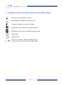
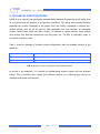
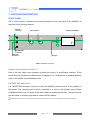
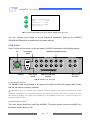
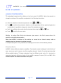
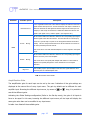
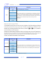
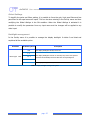
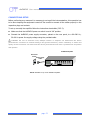
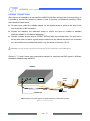
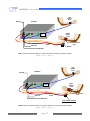
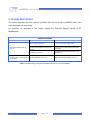
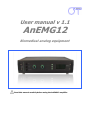
User manual v 1.1 AnEMG12 Biomedical analog equipment Read this manual carefully before using the AnEMG12 amplifier. AnEMG12 User manual v.1.1 pag. 2 AnEMG12 User manual v.1.1 INDEX 1. GENERAL DESCRIPTION ...................................................................................... pag. 5 2. AnEMG12 KIT CONTENT ...................................................................................... pag. 6 3. END USERS ........................................................................................................... pag. 6 Contraindications ............................................................................................ pag. 6 Side effects .................................................................................................... pag. 6 4. SAFETY CAUTIONS AND OTHER WARNINGS ...................................................... pag. 7 5. SYMBOLS USED ON AnEMG12 AND IN THE USER MANUAL .............................. pag. 9 6. TECHNICAL SPECIFICATIONS .............................................................................. pag. 10 7. DETAILED DESCRIPTION ...................................................................................... pag. 12 FRONT PANEL ............................................................................................. pag. Single input connectors: IN 1÷2 ............................................................. pag. PATIENT REF connector ........................................................................ pag. DRL IN connector ................................................................................. pag. DRL OUT connector .............................................................................. pag. Liquid crystal display and keypad............................................................ pag. REAR PANEL ............................................................................................... pag. Power supply socket .............................................................................. pag. Power supply switch .............................................................................. pag. Fuse box ............................................................................................... pag. Fan ....................................................................................................... pag. EMG OUTPUTS connectors ..................................................................... pag. AUX INPUTS connectors......................................................................... pag. SIGNAL OUTPUTS connector .................................................................. pag. 12 12 12 13 13 13 14 14 14 15 15 16 16 16 8. USE OF AnEMG12 ................................................................................................. pag. 17 AnEMG12 CONFIGURATION ...................................................................... pag. Detection Mode ..................................................................................... pag. Amplification gain .................................................................................. pag. High pass and Low pass filters ............................................................... pag. Global Settings ...................................................................................... pag. Backlight management .......................................................................... pag. 17 17 18 19 20 20 CONNECTION SETUP .................................................................................. pag. 21 PATIENT CONNECTION .............................................................................. pag. 22 9. TROUBLESHOOTING ............................................................................................ pag. 24 10. AnEMG12 MAINTENANCE AND STORAGE .......................................................... pag. 25 11. TECHNICAL CHARACTERISTICS ......................................................................... pag. 26 12. WARRANTY ........................................................................................................ pag. 27 Warranty conditions ........................................................................................ pag. 27 pag. 3 AnEMG12 User manual v.1.1 pag. 4 AnEMG12 User manual v.1.1 1. GENERAL DESCRIPTION The AnEMG12 is a multichannel amplifier for bioelectrical signals. It can detect surface electromyographic signals (sEMG), intramuscular electromyographic signals (iEMG), electroencephalographic signals (EEG) and electrocardiographic signals (ECG). The AnEMG12 allows the detection and recording of the electric signals generated by the human body. The signals acquired by the instrument are amplified, filtered, digitally converted optocoupled and than analogue converted and then available at BNC or SCSI Analog Output connectors. The AnEMG12 is a research instrument designed for clinical research carried out by qualified researchers. The AnEMG12 can amplify 12 bioelectrical signals. Several configurations of electrodes are possible by means of a number of cable adapters that can be connected to the two inputs of the amplifier (IN1 and IN2). AnEMG12 allow acquiring, in any configuration, 4 additional signals on the auxiliary inputs (AUXINPUTS). The signals can be generated by other amplifiers (e.g. force, torque, angle, position or trigger signals) that do not need an optical insulation. AnEMG12 instrument is completely safe for the patient. The safety is achieved by means of medical grade electrical insulation of all the circuitry connected to the patient. This user manual refers to all hardware versions of the instrument. pag. 5 AnEMG12 User manual v.1.1 2. AnEMG12 KIT CONTENT 1 multichannel amplifier AnEMG12 1(min) to 2(max) cable adapters to connect electrodes to the amplifier (depending on the number of channels installed into the amplifier); 3 reference straps; Arrays and electrodes of different sizes, depending on the customer request; 1 AnEMG12 user manual. 3. END USER AnEMG12 multichannel amplifier allows invasive and non invasive recording of biopotentials (iEMG, sEMG, EEG, ECG) detected by superficial and invasive electrodes. In the case of sEMG, EEG or ECG recordings the end user must be familiar with the technique and received a proper training in EMG, EEG or ECG detection and interpretation. The detection of iEMG signals is subjected to the insertion of needles or wires into the muscle and must be supervised by trained medical staff. Contraindications AnEMG12 has no particular contraindications when used jointly with personal computers, provided that all the electrical devices connected to it and the power lines comply with safety rules and standards concerning grounding and leakage currents. Side effects In the case of sEMG, EEG or ECG no significant side effects are known. The materials used for manufacturing all the parts in contact with the patient are biocompatible. Possible slight cutaneous allergic reactions (e.g. skin reddening) are reduced to a minimum during short duration electromyographic signal acquisitions. In the case of iEMG, the needles or wires used to detect the signals must be sterilized. No significant side effects are known. pag. 6 AnEMG12 User manual v.1.1 4. SAFETY CAUTIONS AND OTHER WARNINGS The use of the multichannel AnEMG12 amplifier is absolutely forbidden in the following conditions: While other monitoring devices are in use with the patient. While electro surgery equipment, short waves or microwaves therapy devices are used. By mentally impaired people. Whenever the equipment is damaged. In proximity of inflammable substances (especially inflammable liquids and gases) or in environments with high concentration of oxygen. On patients carrying life-supporting equipment that might be adversely affected by electromagnetic interferences, such as pacemakers, etc. The following cautions should be observed: The detection of iEMG signals must be supervised by trained medical staff. Only use electrodes supplied by the manufacturer: AnEMG12 is guaranteed to achieve tested performance only if used with electrodes supplied by the manufacturer. Contact the manufacturer immediately if extraneous materials permeate into the device (liquids, powders, etc.). In case of hard shocks suffered by the AnEMG12 (like a drop to the floor, etc.), verify that no crack or any other kind of damage of the box resulted from the shock. In case of doubt, please contact the manufacturer. The AnEMG12 is subject to electromagnetic interference that is not dangerous for the patient (such as electrostatic or electromagnetic interference generated by electrical motors and other sources). This interference may affect the measurements of the physiological variables derived from the EMG or EEG signals. These measurements are not meant to be used for diagnostic purposes, and thus these signal alterations cannot be dangerous for the patient, please always take into account the presence of noise in your signal processing tasks and evaluations. Before making any measurement, it is mandatory to check the quality of the grounding of the power line to which the AnEMG12 is connected. The use of electrical devices with grounding connections not compliant with safety standards represents a high risk for the patient and the operator. The connection between AnEMG12 and other electrical devices (e.g. a PC) must be done in compliance with the European standard EN 60601-1-1 on medical devices. pag. 7 AnEMG12 User manual v.1.1 Always use the AnEMG12 with a PC manufactured in compliance with the European standards EN 60950 (safety standard for information technology devices), EN 55022 (EMC standard) and EN 55024 (immunity standard). Electrical motors and other electrical devices (relay, remote control switch, neon lights, etc.) near the AnEMG12 electromyography can be a source of electromagnetic interference that disturbs the amplifier. The presence of such electromagnetic fields is not dangerous for the patient, but can alter the electromyographic signals and cause unreliable measurements. The use of the AnEMG12 is restricted to skilled personnel. Incorrect measurements can arise when unskilled personnel use the device in presence of strong sources electromagnetic interference (e.g. strong electromagnetic fields). The presence of interference in the signals is easily recognised by skilled personnel. AnEMG12 is not designed to be portable equipment. Should it be necessary to move the AnEMG12 amplifier, it must be properly packaged to avoid typical vibrations and shocks arising from transportations. Vibrations could cause the release of metallic particles inside the appliance, such as screws, nuts and bolts, that could compromise the safety of the patient and the integrity of the appliance. pag. 8 AnEMG12 User manual v.1.1 5. SYMBOLS USED ON AnEMG12 AND IN THE USER MANUAL Class BF for circuitry applied to patient. Read carefully the instruction remarks before use. Dangerous voltage level, power line voltage. Multifunction keys to select and modify parameters. Multifunction key to enter the selected parameter value. Signals input. Signals output. I O Power on (I): switch on power line voltage supply. Power off (O): switch off power line voltage supply. pag. 9 AnEMG12 User manual v.1.1 6. TECHNICAL SPECIFICATIONS AnEMG12 is an optically and galvanically insulated device designed to guarantee a high safety level for the patient and the operator in all operating conditions. The optical and galvanic insulation separates the circuitry connected to the patient from the circuitry connected to external nonmedical devices, such as the PC used for data acquisition and user interface. An embedded circuitry, called Driven Right Leg (DRL) circuitry, is available to reduce common mode voltage noise arising from electrical interference from the power line. The DRL is particularly useful in monopolar acquisition mode. Table 1 shows an example of possible probes configurations with the available versions of the AnEMG12. Device configuration Example of probes configuration 12 bioelectrical inputs two 6 channel probes 4 auxiliary inputs 4 not amplified analog input TAB. 1: Examples of probes configurations with AnEMG12 amplifier. As shown in the examples, it is possible to simultaneously acquire signals with two different probes. This is necessary when signals from different muscles or of different type need to be recorded at the same time together. pag. 10 AnEMG12 User manual v.1.1 AnEMG12 technical specifications are shown in TAB. 2. Amplification channels (IN1÷2) Selectable gain OFF, 100, 200, 500, 1000, 2000, 5000, 10000 V/V Selectable bandwidth High pass filter: 3, 10, 100, 200 Hz Low pass filter: 130, 500, 900, 4400Hz Maximum input range 50 mVPP Noise level referred to input < 4 VRMS Input impedance > 1011 CMRR > 95 dB Output range -5V ÷ 5 V Insulation voltage 4.000 VDC Auxiliary channels (AUX-INPUTS 1÷4) Input range ±5V Bandwidth Channels are not filtered Gain 1 V/V Input impedance 200 kΩ TAB. 2: AnEMG12 technical specification pag. 11 AnEMG12 User manual v.1.1 7. DETAILED DESCRIPTION FRONT PANEL FIG. 1 shows controls, indicators and connectors present on the front panel of the AnEMG12 as described in the following sections. DRL IN connector IN connectors DRL IN IN 2 Liquid crystal display IN 1 AnEMG12 OK DRL OUT EMG AMPLIFIER PATIENT REF PATIENT REF connector DRL OUT connector PATIENT REF Keypad FIG. 1: AnEMG12 front panel Single input connectors: IN 1÷2 Each of the two single input connectors provides the input to 6 amplification channels. These inputs allow the connection of different type of adapters. For a complete list of available adapters refer to the website: www.otbioelettronica.it PATIENT REF connector The PATIENT REF connector is used to connect the AnEMG12 reference point of the amplifier to the patient. The reference point must be connected to a point on the patient's body without myoelectric activity (e.g. the ankle or the wrist) using the supplied ground strip. The strip must be wet with water to ensure a good electric contact with the patient. REMARK: failure in connecting this electrode prevents the correct acquisition of the EMG signal. pag. 12 AnEMG12 User manual v.1.1 DRL IN connector The DRL IN has a double function, it is the input of the interference reduction circuitry DRL and one input of each AnEMG12 amplification chain, when in floating monopolar mode. In case of high levels of electromagnetic interference, it may be necessary to activate the DRL noise reduction circuitry. To activate the DRL noise reduction circuitry a ground strip must be connected to the patient at a point with no bioelectrical activity (wrist or ankle). Using the provided cable, the strip must be connected to the DRL IN connector. An additional ground strip must be connected at a point with no bioelectrical activity on the patient and, using the provided cable, to the DRL OUT connector. When using the floating monopolar detection mode (Mode: Float. Monop.) the DRL IN is also one of the two inputs of all AnEMG12 first stages. Thus, when the amplifier is in this mode, it is mandatory to connect the patient to this input. A ground strip must be wet with water to ensure a good electric contact with the patient and has to be connected to a point on the patient's body without bioelectrical activity (e.g. the ankle or the wrist) and, using the provided cable, to the DRL IN connector. It is very important that the two strips connected to PATIENT REF and DRL IN connectors input do not touch each other. REMARK: failure in connecting this electrode prevents the correct acquisition of the EMG signal in floating monopolar mode (MODE: Float. Monop.). DRL OUT connector The DRL OUT is the output of the DRL interference reduction circuitry. The DRL OUT should be connected with the provided cable to a ground strip. The strip has to be wet to ensure a good electric contact with the patient. It is not strictly required to connect this strip at a point without bioelectrical activity, whereas this is strictly required for DRL IN and PATIENT REF. REMARK: failure in connecting this electrode prevents the correct acquisition of biopotentials in case of high levels of electromagnetic interference. Liquid crystal display and keypad The liquid crystal display is turned on when the AnEMG12 amplifier is switched on. After an introducing screen-shot, the AnEMG12 settings are presented as shown in FIG. 2. pag. 13 AnEMG12 User manual v.1.1 IN 1 MENU OK Mode: Chained Diff. GAIN: 10.000 HP Filter: 10 Hz LP Filter: 0,9 KHz Enter Set-Up FIG. 2: Liquid crystal display screen-shot example displaying the IN 1 menu This user interface gives access to all the instrument parameters. Refer to the AnEMG12 CONFIGUARTION section for detail about instrument settings. REAR PANEL Figure 3 shows the connectors on the rear panel of AnEMG12 described in the following sections. Fan Power Supply Switch ANALOG Outputs BNC Connector AUX INPUTS EMG OUTPUTS 0 1 OUT 1 OUT2 OUT 3 OUT4 OUT 5 OUT 6 IN 1 IN 2 OUT 7 OUT 8 OUT 9 OUT 10 OUT11 OUT12 IN 3 IN 4 MADE IN ITALY Fuse Box SIGNAL OUTPUTS Power Supply Socket USB ANALOG Outputs SCSI Connector Analog Input Connector FIG. 3: AnEMG12 rear panel view Power supply socket The AnEMG12 must be connected to the power line socket only with the supplied cable. Ensure that the wall socket is properly grounded. DANGER: the use of extension cords, multiple sockets or adapters can impair the performance of the ANEMG12. Connection to sockets without proper grounding (e.g. lacking the “earth” conductor) or with bad quality grounding can impair the performance of the AnEMG12 and cause a potential risk for the patient and the operator. Power Supply Switch The Power Supply Switch turns on/off the AnEMG12. The switch position I turns the AnEMG12 on; the switch position O turns it off. pag. 14 AnEMG12 User manual v.1.1 The Power Supply Switch breaks both the power line wires to improve the safety. When the AnEMG12 amplifier is not in use, turn it off by this switch. Fuse Box In the same block of the power supply switch and the power supply connector there is a sliding box with one fuse for each power line wire. For proper operation both fuses must conduct electricity. A cover opening fuse breakdown indicates excessive current absorption and usually is a symptom of something seriously burnt. Have the AnEMG12 properly checked by qualified personnel before replacing the fuses. Replacing the broken fuses may not restore the AnEMG12 to its original integrity without a careful diagnosis of the causes that made the fuses burnout. The anomaly may have rendered the device no longer compliant with the safety standards. Should it be necessary, in any case replace the fuses with others of the same type. Fuse type is indicated on the rear ID label. DANGER: Replacing the fuse with other fuse types can be very dangerous for patient and the operator. Fan The fan on the rear panel cools the internal circuitry of the instrument. The airflow to avoid amplifier overheating enters the AnEMG12 from the slits on the bottom panel and exits through the fan. The following cautions must be observed: Ensure to leave at least 8 cm of clear space behind the ANEMG12 to ensure a suitable airflow. Do not obstruct the slits on the bottom panel. Do not stop the fan. Do not obstruct the grid on the rear panel (see FIG. 4). REMARK: blocking the airflow can cause overheating and device breakdown. Ensure that the fan rotates freely and that nothing obstructs or blocks it. Hot air flow (fan) Cold airflow (lower panel slots) > 8 cm FIG. 4 Airflow and minimum required space behind the device pag. 15 AnEMG12 User manual v.1.1 Analog OUTPUTS Connectors These BNC type connectors allow displaying on a oscilloscope all bioelectrical signals filtered and amplified. AUX INPUTS connectors These BNC type connectors can be used to acquire external amplified signals, in the range ± 5 V, together with the bioelectrical signals. The four auxiliary inputs work even if no other inputs of the front panel are used. SIGNAL OUTPUTS connector This SCSI type connector allows to connect a NI card to display on a PC all 12 bioelectrical signals filtered and amplified + four AUX INPUTS channels. pag. 16 AnEMG12 User manual v.1.1 8. USE OF AnEMG12 AnEMG12 CONFIGURATION The embedded keypad and the display on the front panel of AnEMG12, allow the operator to change the settings of the amplifier as explained in the following instructions: Move the selection to the desired parameter using Press and keys. to confirm the parameter selection; only the parameter will be negative displayed to indicate that it is possible to change the value of the selected parameter. Scroll the available options and select the desired value using the Press and keys. to confirm the new value. Selecting the option Enter Set-Up the instrument give access to the Set-Up menu where it is possible to set additional parameters. When the AnEMG12 is switched off the settings are stored into an internal memory and are reloaded when the instrument is switched on again. A complete description of the parameters and settings can be found in the following sections. Detection Mode AnEMG12 feature different detection modalities. The detection mode is displayed in the first line of every input menu and is common to all the amplifier channels. In table 3 are listed and described all the available options. To better understand how the different mode works, it is important to remember that each of the two inputs of the amplifier manages 6 signals (IN 1 and IN2). Each channel amplifies the difference between two signals. pag. 17 AnEMG12 User manual v.1.1 Parameter Available options Description It is a single differential mode. Each channel amplify the difference between a signal and the subsequent one. The last channel of each input is obtained as Differential difference between the last signal and the first signal of the same input. For example, in this mode, the channel 6 is obtained as difference between the signal 6 (last signal of IN 1) and the signal 1 (first signal of IN 1). All the channel makes the difference between the corresponding input signal and the signal at the DRL IN connector. The DRL IN must be connected, by means of a ground strip to a point on the body patient without bioelectrica Float. Monop. activity. This is a monopolar detection since all the channels are referred to the same potential present at DRL IN. MODE This mode can be used with standard adapters to detect signals in monopolar mode. All the channel makes the difference between the corresponding input signal and the reference point of the amplifier. Refer. Monop. This mode can be used jointly with adapter with suffix M1. These kinds of adapters are specially designed to reduce interferences in monopolar detection. Bipolar This modality require special adapters that allow the signals detection from electrode pairs as standard bipolar EMG. TAB. 3: Detection mode details Amplification Gain The amplification gain for each input can be set by the user. Indication of the gain settings are displayed at the second line of every input menu. The gain by default can be different for each amplifier input. Browsing the different input menus, by means of and keys, it is possible to see all the different gains. Activating the Global Settings configuration (Refer to the Set-Up menu), the gain of all inputs is force to be equal. In this case, browsing the different input menus, all the input will display the same gain value than can be modified in any input menu. In table 4 are listed all the available gains. pag. 18 AnEMG12 User manual v.1.1 Parameter Available options OFF Description The corresponding input is turned OFF 100 200 All the signals related to the corresponding input are amplified by respective 500 GAIN the factor. In case of EMG recordings lower values can be used during high 1.000 level contractions or during electrically elicited contractions. Higher values are 2.000 suggested when recording from deep muscles or during low level contractions. 5.000 10.000 TAB. 4: Amplification gain description High pass and Low pass filters The bandwidth for each input can be set by the user. Indication of the filters settings are displayed at the third and fourth line of every input menu. The filters by default can be different for each amplifier input. Browsing the different input menus, by means of and keys, it is possible to see all the different cut off frequencies. Activating the Global Settings configuration (Refer to the Set-Up menu), the cut off frequencies of all inputs are force to be equal. In this case, browsing the different input menus, all the input will display the same High pass and low pass values than can be modified in any input menu. In table 5 are listed all the available cut off frequencies. Parameter Available options Description 3 Hz 10 Hz HP Filter 100 Hz 200 Hz All the signals related to the corresponding input are high pass filtered and low pass filtered with the 3 dB cut off frequency displayed. It is up to the user 130 Hz to select the correct filters value for the conditioning of the desired signals. 500 Hz LP Filter 900 Hz 4.4 kHz TAB. 5: Filters description pag. 19 AnEMG12 User manual v.1.1 Global Settings To simplify the gains and filters setting, it is possible to force the gain, high pass filters and low pass filters to be equal across all inputs. This can be done entering in the Set-Up menu and then modifying the Global Settings in the ON condition. When the Global Settings is activated it is possible to modify the parameter from any input menu and the changes will be applied to any other input. Backlight management In the Set-Up menu it is possible to manage the display backlight. In table 6 are listed and explained all the available option. Parameter Available options OFF Description The display backlight is always turned off 5 s Backlight time 10 s The display backlight is turned on when any keys of the front panel is pressed is automatically turned off after the corresponding time 15 s ON The display backlight is always turned on TAB. 6: Display backlight management option pag. 20 AnEMG12 User manual v.1.1 CONNECTIONS SETUP Before performing any measure it is necessary to set up all the instrumentation; this operation has to be done keeping the equipment turned off. Be careful to connect all the cables properly to the respective plugs and sockets. To set up correctly the amplifier follow the instructions hereinafter (FIG. 5): Make sure that the AnEMG12 power on switch is set in “O” position. Connect the AnEMG12 power supply connector, placed on the rear panel, to a 90÷260 VAC, 50÷60 Hz power line supply voltage using the provided cable. DANGER: the use of extension lead, multiple sockets or adapters can deteriorate the device performances. Connection to sockets lacking in the ground conductor (“earth” conductor) or with a bad quality of this connection can deteriorate the device performances and cause a potential risk for patient and operator. AnEMG12 Amplifier Power line socket Power supply cable FIG. 5: Standard set up of the AnEMG12 amplifier pag. 21 AnEMG12 User manual v.1.1 PATIENT CONNECTION After the correct installation of the amplifier AnEMG12 and after verifying that it works properly, it is possible to connect the sensors to patient in order to perform a biopotential recording. Follow the instructions listed below: For each input, select the suitable adapter for the measurement to perform and plug it into one of the IN1 or IN2 connectors. Connect the adapters, the electrodes arrays or matrix, the wires or needles or standard electrode suitable for the desired application. Connect a patient ground strip to PATIENT REF plug with the enclosed cable. The strip has to be wet with water to assure a good electric contact with the patient and has to be connected on a point without any bioelectrical activity (e.g. the ankle or the wrist, FIG. 6). REMARK: the lack of this connection prevents the correct acquisition of the EMG signal. Figures 6, 7, 8 and 9 show some connections example for acquiring the EMG signals in different modalities available using AnEMG12. AnEMG12 Patient wrist Cables PATIENT REF Patient reference strip Adapter FIG. 6: Patient connection diagram for signal acquisition in differential modality (Mode: Differential) pag. 22 AnEMG12 User manual v.1.1 Left Patient wrist DRL IN AnEMG12 Right Patient wrist Cables DRL OUT Patiente reference strip Adapter PATIENT REF FIG. 7: Patient connection diagram for signal acquisition in floating monopolar modality (Mode: Float. Monop.). Left Patient wrist DRL IN AnEMG12 Right Patient wrist Patiente reference strip Cables DRL OUT PATIENT REF OT Monopolar Adapter FIG. 8: Patient connection diagram for signal acquisition in referred monopolar modality (Mode: Refer. Monop.). pag. 23 AnEMG12 User manual v.1.1 9. TROUBLESHOOTING This section describes the most common problems that may be found by AnEMG12 users, with some suggestions to solve them. For problems not described in this section contact the Technical Support Service of OT Bioelettronica. GENERAL PROBLEMS Problem The electromyograph does not turn on The instrument turns on, but the characters are not shown properly on the display Possible cause Solution Power supply switched off Turn to “I” the power supply switch. Power supply cable is not inserted properly in the amplifier or into the wall socket Check the power supply cable and the socket connection Breakdown of the fuses Contact the Technical Support Service of OT Bioelettronica Ambient temperature is too low Wait that the electromyograph warms up TAB. 7: Troubleshooting of the general problem that can occur using the AnEMG12 pag. 24 AnEMG12 User manual v.1.1 10. AnEMG12 MAINTENANCE AND STORAGE AnEMG12 has to be used in the following ambient conditions: Temperature: from 0°C to +40°C Maximum relative humidity: 75% Atmospheric pressure: from 700 hPa to 1060 hPa It is recommended to turn off the AnEMG12 at the end of each measurement session, and to remove all the cables and connections. The AnEMG12 should be stored with all the enclosed accessories on a safe desk far from all the situations listed in the section Warnings. AnEMG12 should be stored in the following ambient conditions: Temperature: from –20°C to +40°C Maximum relative humidity: 75% Atmospheric pressure: from 700 hPa to 1060 hPa Cleaning: use only a dry cloth to clean the device. It is recommended to plan a device check every 24 months with the manufacturer. The AnEMG12 should be repaired by the manufacturer only. Every repair executed by unauthorized personnel will be considered as a device violation voids the manufacturer’s warranty. Disposal The device and the accessories should be disposed in compliance with the relative standards in special equipped areas or with special waste. pag. 25 AnEMG12 User manual v.1.1 11. TECHNICAL CHARACTERISTICS Model: AnEMG12 Risk class: IIa in compliance with the standard 93/42/CEE. Insulation class: BF type applied part, in compliance with the European standard EN 60601-1. Classification: - class I, about the protection from indirect contact. - IP20, about the penetration of fluids and dust; device not protected. Case: painted metallic case. Power supply: voltage from 90Vac to 260Vac ± 10%, frequency from 47 to 400Hz. Consumption: 30 W. Limitations: the device is not suitable for use in environments with high oxygen concentration and/or flammable fluids and/or gases; do not use with electro-surgery or short wave/microwave therapy equipment. Working conditions: device suitable for continuative work. Protections: 2 x 1 A fuses. Input channels: up to 16: 12 optocoupled + 4 not optocoupled Bioelectrical Amplifier: Maximum input range: 50 mVPP Bandwidth: 3 ÷ 4400 Hz Total noise (RTI) < 4VRMS (monopolar) < 1VRMS (differential) Selectable gain: 100, 200, 500, 1000, 2000, 5000, 10000 Input impedance > 1011 on the entire bandwidth CMRR > 95 dB Visualization: graphic LCD 128x64 pixel display. Commands: 7 keys protected by polycarbonate membrane. Dimensions: 350 x 271 x 85 mm Weight: 2 Kg. pag. 26 AnEMG12 User manual v.1.1 12. WARRANTY AnEMG12 is covered by a 24 months warranty starting from the purchasing date of the electronic parts. Connection cables are covered by a 24 months warranty. The warranty is void in case of device violation or in case of intervention from unauthorized staff. Warranty conditions are reported hereinafter. Warranty conditions 1. The warranty lasts 24 months on the electronic parts. Warranty is provided by the manufacturer. 2. The warranty covers only device damages that cause malfunctioning. The product must have the same serial number indicated on this certificate, or the warranty is released. 3. The warranty covers only the cost of repair or substitutions of defective components, including the costs of labour. 4. The warranty is void in case of damages caused by negligence, use not compliant with the instructions supplied, unauthorized repairs and accidental circumstances, especially for the external part. 5. The warranty is void with damages caused by incorrect power supply. 6. The warranty is not applied on all the parts subject to wear and tear. 7. The warranty does not include the shipment costs. 8. After 24 months the warranty is released. All the substituted parts, the labour costs and the shipment costs will be charged to the purchaser according to the rates in force. pag. 27 AnEMG12 User manual v.1.1 Produced and distributed by: OT Bioelettronica C.so Unione Sovietica 312 10135 – Torino (TO) - ITALY Tel:+39.011.6198498 Fax:+39.011.6198498 URL: www.otbioelettronica.it e-mail: [email protected] pag. 28