1
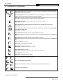
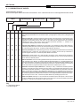
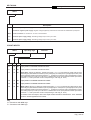
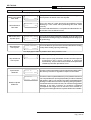
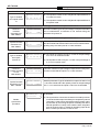
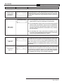
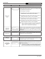
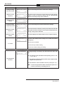
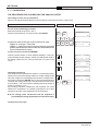
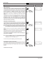
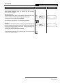
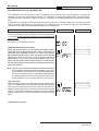
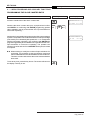
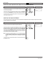
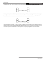
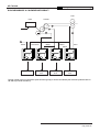
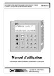
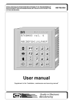
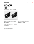
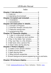
INSTRUMENT FOR THE SYNCHRONISM OF MOTOR SPEED AND SPACE IN RESPECT TO A MASTER FREQUENCY HB 760.04A Electronic Instrument B760H04 rel. 7 ABCDEFGHIJKLMNOP F1 F2 A C 1 2 3 D E F 4 7 I /O B 5 L/V 8 6 9 PASS 0 User manual Supplement to the Installation, maintenance and servicing manual HB 760.04A Quality in Electronic Manufacturing LIST OF SUBJECTS DEALT WITH IN THIS MANUAL CHAP. 1 - INTRODUCTION - Supplementary nature of manual References Responsibility and validity Description of operation CHAP. 2 - OPERATOR / MACHINE INTERFACE - Description of keyboard - Description of inputs - Description of outputs CHAP. 3 - SETTING UP FOR OPERATION - Set-up - Calibrations CHAP. 4 - USE - Work programmes and auxiliary functions - Operation graphs and tables CHAP. 5 - ASSISTANCE - Inputs and outputs troubleshooting - How to complete the technical assistance fax form - Warranty 1-1 1-2 1-3 1-4 2-1 2-2 2-3 3-1 3-2 4-1 4-2 5-1 5-2 5-3 Pag. 1 di 47 HB 760.04A Quality in Electronic Manufacturing CHAPTER 1 INTRODUCTION Supplementary nature of manual References Responsibility and validity Description of operation Pag. 2 di 47 HB 760.04A Quality in Electronic Manufacturing 1 - 1 SUPPLEMENTARY NATURE OF MANUAL This manual is to be considered as a supplement to the Installation, maintenance and servicing manual, which contains information on wiring, checking and eliminating faults, start-up and maintenance procedures. This manual gives instructions on the use and correct programming of the instrument. You are urged, therefore, to read the manual carefully and, if you have any queries, to contact QEM for further explanations by sending the assistance fax contained in the manual. 1 - 2 REFERENCES The documentation on the instruments designed and sold by QEM has been divided into different booklets for effective and speedy consultation, based on the specific type of information required. Hardware structure Installation, maintenance and servicing manual Explanation of software. Basic information on the standard hardware in the series plus customisation possibilities. All the necessary information for installation, maintenance and servicing. This is this manual, giving all the necessary information for the understanding and use of the instrument described. The manual deals with the instrument software, with information on the understanding, programming, calibration and use of the instrument described. After installing the instrument, following the instructions in the installation, maintenance and servicing manual, this user manual gives all the necessary instructions on the correct use and programming of the instrument. This booklet is appended to the user manual and describes the standard hardware configuration for the series of instruments described. It also gives the standard electrical, technical and mechanical specifications of the series, together with the hardware customisation possibilities in relation to the different software versions. All the essential details on the correct maintenance and installation. The aim is to provide you with valid and accurate information for the manufacture of products of recognised quality and reliability. It also gives valid supporting information for servicing applications with QEM instruments installed. User manual Pag. 3 di 47 HB 760.04A Quality in Electronic Manufacturing 1 - 3 RESPONSIBILITY AND VALIDITY RESPONSIBILITY QEM declines all responsibility for any injury to persons or damage to objects resulting from the failure to observe the instructions and rules in this manual and the Installation, maintenance and servicing manual. It is furthermore specified that the customer/purchaser is bound to use the instrument according to the instructions provided by QEM and, if any doubts arise, to send a written query to QEM. Any authorisation for exceptions or substitutions in use, if contested, will be deemed valid by QEM only if in writing. The reproduction or handing over of all or part of this manual to third parties without the written authorisation of QEM is forbidden. Any transgression will result in a claim for compensation for the damages sustained. All rights deriving from patents or designs are reserved. QEM reserves the right to make partial or complete modifications to the characteristics of the instruments described or corresponding documentation. Objective The objective of this manual is to give the general rules for the use of the instrument described. Conservation of parameters Write down all the instrument setting and programming parameters and keep them in a safe place, to facilitate any future replacement or servicing operations. VALIDITY This manual is applicable to all instrumentation designed, manufactured and tested by QEM with the same order code. This document is valid in its entirety, barring errors or omissions. Instrument release Manual Release 6 6 7 0 1 2 7 3 Modifications to manual New Manual Modified the analog output description and calibration. Manual for new hardware version (A) Inserted parameter for "Keyboard disabled" set-up Inserted BACKUP/RESTORE function. Modified the introduction of the proportional gain value. Date of modifications 29 / 01 / 97 24 / 06 / 97 20 / 05 / 98 01 / 06 / 98 Pag. 4 di 47 HB 760.04A Quality in Electronic Manufacturing 1 - 4 DESCRIPTION OF OPERATION The HB 760.04 is used for synchronising a series of motors that have to maintain constant rapports in time and space (calendering lines, rolling mills, extruders) therefore controlling the synchronism between two counts (master and slave) by means of the analogical output. The slave / master ratio has a field of variation between 2.00000 and 0.00001 and the two frequencies must not exceed 20-100 Khz. Restart can be enabled on the encoder zero impulse or on a home quota, using the absolute slave count or by actuating a phase different to recover the mechanical position in respect to the master. A master simulation input can be used in manual to facilitate calibration of the machine and the instrument. Two tachometers are provided (master and slave) to visualise the speeds so that the operator has a clear vision of how the system is moving. Using the input expansion (order code "E") it is possible to select externally a chart of ratio or percentage (slave / master) (max. 99) memorised by the instrument. The instrument is provided with a BACKUP/RESTORE function for storage and recovery of data relative to the instrument's preset parameters (set-up, axis calibration, ...), excluding work parameters. Data is stored on a nonvolatile device. Pag. 5 di 47 HB 760.04A Quality in Electronic Manufacturing CHAPTER 2 OPERATOR / MACHINE INTERFACE Description of keyboard Description of inputs Description of outputs Pag. 6 di 47 HB 760.04A Quality in Electronic Manufacturing 2 - 1 DESCRIPTION OF KEYBOARD Key PASS 0 ÷ Function 9 Normal operation: pressed after the F1 and "F2" keys, they select the functions available. Data input: allows entry of data. Normal operation: selects the display of the cycle. Impulse pressure selects the successive display. Continuous pressure selects the previous display. Data input: scrolling of the various parameters. Impulse pressure selects the successive parameter. Continuous pressure selects the previous parameter. Normal operation: selects the display within the chosen function. Data input: not used. Normal operation: allows access to and exit from the available manual functions. Data input: not used. Normal operation: allows access to and exit from introduction of the sychronism percentage or the slave / master ratio. Data input: not used. F1 Normal operation: allows selection of the available functions. Data input: allows the output of the functions which can be selected with F1 + Numerical key. F2 Normal operation: allows selection of the available functions. Data input: allows the output of the functions which can be selected with F2 + Numerical key. Normal operation: not used. Data input: Inserts the decimal point. Normal operation: not used. Data input: Inserts or removes the +/- sign. I /O Normal operation: not used. Data input: deletes the input value and reverts to the old value. Normal operation: not used. Data input: stores the datum entered. PASS F1 + F1 + 1 F1 + 2 F1 + 0 Access to password-protected functions. A Choice of the table to be executed. B Modification of the phase difference between the slave and master position. I /O Input and output diagnostics. Continued on next page Pag. 7 di 47 HB 760.04A Quality in Electronic Manufacturing Key Function A P.I.D. parameter programming. B Programming of the master simulation percentage. C Programming of the slave / master run percentage or slave / master ratio. F2 + 1 F2 + 2 F2 + 3 Pag. 8 di 47 HB 760.04A Quality in Electronic Manufacturing 2 - 2 DESCRIPTION OF INPUTS Characteristics of inputs Refer to the chapter entitled Electrical characteristics in the Hardware structure booklet appended to this manual. Operating logic Name Activation mode Polarizer Description I1 ON I P1 Phase. With the set-up parameter "Restart slave phase" = 1 or 2, synchronise the master with the slave determining the phase difference count between input I1 (managed by the master) and Z1 (managed by the slave). I2 ON/OFF C P1 Start (on) / Stop (off). The start is accepted only when I6 and I8 = ON. With input I2 commuting OFF to ON, the instrument starts synchronism with the master. With input I2 commuting ON to OFF the instrument interrupts the synchronism and the axis returns to zero speed with the programmed ramp procedures maintaining the axis in space reaction. With the "Restart synchronism procedure" = 1, activation of I2 commands the restarting of the master / slave phase. I3 ON I/C P1 Increase phase difference. Enabled during synchronism, this increases the slave's phase difference, maintaining unaltered the slave / master ratio. The speed and the type of variation are set in set-up. Activated for 2 seconds together with input I4, it resets the phase difference introduced. I4 ON I/C P1 Decrease phase difference. Enabled during synchronism, decreases the slave phase difference maintaining unaltered the slave / master ratio. The speed and the type of variation are set in set-up. Activated for 2 seconds together with input I3, it resets the phase difference introduced. I5 ON I P1 Positioning. If manual is active (I6 = OFF) and also the stop (I2 = OFF), this actives the procedure for positioning on the home quota or on the zero impulse (when enabled in set-up). The home quota is positioned on the slave axis absolute position. I6 ON/OFF C P1 Manual / Automatic. In function of the logical state of this input, selects the function mode of the instrument: ON = Automatic, OFF = Manual. In manual it enables the simulated rotation (I7 = ON) and programming of the set-up parameters. In automatic it synchronises the master count with the slave when activated by start (I2 = ON). If input I6 is commuted during a simulated synchronism in manual or automatic, the axis returns to zero speed with the programmed ramp procedure and the axis maintains space control. I7 ON C P1 Simulation / Exclusion of phase difference. In manual (I6 = OFF), it enables the simulation procedure utilised in moving the slave axis by releasing it from the master count generated within the instrument. With the "Restart synchronism procedure" = 1 (set-up), when a simulationis made, the synchronism counts are reset. The simulation procedure is also utilised when calibrating the P.I.D. parameters of the slave axis. In automatic (I6 = ON), it excludes the phase difference procedure (when enabled) so that with inputs I3 and I4 or from the keyboard it is possible to return the slave to a correct physical position in respect to the master; then when input I7 turns to OFF, it restores the phase difference by resetting the previous one. I8 ON C P1 Slave axis enabled. With input I8 = ON, the slave axis controls the space. With input I8 = OFF, the space control is disabled and all other inputs are ignored. If the input I8 turns to ON with "Restart synchronism procedure" = 0 (set-up), the synchronism counts return to zero. Key C = Continuous signal I = Impulse signal Pag. 9 di 47 HB 760.04A Quality in Electronic Manufacturing Name Description + Transducers positive power supply. Positive voltage supplied by instrument for instrument and transducers inputs power. - Transducers negative power supply. Negative voltage supplied by instrument for instrument and transducers inputs power. GND Ground connection. A conductor of Æ 4 mm is recommended. Vac Instrument power supply voltage. Alternating voltage as per code in your order. Vac Instrument power supply voltage. Alternating voltage as per code in your order. COUNT INPUTS Name Operating logic Polarizer F1 N/P PE Input "phase A" incremental transducer for slave. F1 N/P PE Input "phase B" incremental transducer for slave. Z1 N/P PE Slave phase. With set-up parameter "Restart slave phase" = 3 or 4, it synchronises the master with the slave determining the phase difference between input Z2 (managed by the master) and Z1 (managed by the slave). With set-up parameter "Restart synchronism procedure" = 1, it resets the synchronism if this is activated before a start. The reading frequency for this input is 20 Khz. It is disabled when in set-up the parameter "Restart synchronism procedure" = 1, when synchronism is active and positioning is under way (ex. home). F2 N/P PE Input "phase A" incremental transducer for master. F2 N/P PE Input "phase B" incremental transducer for master. Z2 N/P PE Master phase. With set-up parameter "Restart slave phase" = 3 or 4, it synchronises the master with the slave determining the phase difference between input Z2 (managed by the master) and Z1 (managed by the slave). With set-up parameter "Restart synchronism procedure" = 1, it resets the synchronism if this is activated before a start. The reading frequency for this input is 20 Khz. It is disabled when in set-up the parameter "Restart synchronism procedure" = 1, when synchronism is active and positioning is under way (ex. home). For details of the count inputs, refer to the chapter entitled Electrical characteristics in the Hardware structure booklet appended to this manual. Key N = Transducer with NPN logic. P = Transducer with PNP logic. Pag. 10 di 47 HB 760.04A Quality in Electronic Manufacturing Characteristics of input expansion with BINARY code (option E) Refer to the chapter entitled Electrical characteristics in the Hardware structure booklet appended to this manual. Name Operating logic Activation mode Polarizer Description I9 ON C P2 Selection of synchronism ratio table. With set-up parameter "Input expansion functions" on 0 select table 1. With set-up parameter "Input expansion functions" on 1it becomes a bit with value 20 for the units or tenths in the BCD code. With set-up parameter "Input expansion functions" on 2 it becomes a bit with value 20 for the binary code. I10 ON C P2 Selection of synchronism ratio table. With set-up parameter "Input expansion functions" on 0 it selects table 2. With set-up parameter "Input expansion functions" on 1it becomes a bit with value 2o for the units or tenths in the BCD code. With set-up parameter "Input expansion functions" on 2 it becomes a bit with value of 21 for the binary code. I11 ON C P2 Selection of synchronism ratio table. With set-up parameter "Input expansion functions" on 0 it selects table 3. With set-up parameter "Input expansion functions" on 1 it becomes a bit with value 22 for the units and tenths in the BCD code. With set-up parameter "Input expansion functions" on 2 it becomes a bit with value 22 for the binary code. I12 ON C P2 Selection of synchronism ratio table. With set-up parameter "Input expansion functions" on 0 it selects table 4. With set-up parameter "Input expansion functions" on 1 it becomes a bit with value 23 for the units and tenths in the BCD code. With set-up parameter "Input expansion functions" on 2 it becomes a bit with value 23 for the binary code. I13 ON C P2 Enter table. This executes the selected table with inputs I9÷ I12. I14 ON I/C P2 Increase ratio. Enabled during synchronism, it increases the slave / master ratio. The speed and type of variation are set in set-up. I15 ON I/C P2 Decrease ratio. Enabled during synchronism, it decreases the slave / master ratio. The speed and type of variation are set in set-up. I16 ON I P2 Phase difference counts. Reading is enabled with set-up parameter "Restart synchronism procedure" on 1 (set-up), it resets to zero the synchronism counts by loading a preset value on the master and slave when activated before a start. Key C = Continuous signal I = Impulse signal Pag. 11 di 47 HB 760.04A Quality in Electronic Manufacturing 2 - 3 OUTPUTS Characteristics of inputs Refer to the chapter entitled Electrical characteristics in the Hardware structure booklet appended to this manual. Name Operating logic Activation mode Polarizer Description U1 ON C C1 Tolerance. Signals that positioning has been made correctly, therefore within the limits set by the "Tolerance" parameter. It can be used, for example, to enable an operation successive to positioning. U2 ON C C1 Synchronism. This is energised automatically after a start when the slave motor is in synchronism with the master. With the set-up parameter "Restart synchronism procedure" on 1, the comparison of the synchronism is always enabled. U3 ON C C1 Slave axis operation enabled. This is energised when input I8 = ON. The energising of this output, when correctly connected, has the function of enabling the functions of an operation. It is energised 500 ms after the instrument is switched on and is de-energised when switched off or when the instrument signal "Slave axis disabled" appears. U4 ON C C1 Slave axis forward/back. The output is energised only with the parameter "Choice of slave axis servocontrol" on 1 (see chapter 3, paragraph 3-2 "Procedure for analog output calibration"). It is de-energised when the rotation is forward and energised when in reverse. U5 ON I C1 BCD code unit enabled. It is energised with set-up parameter "Input expansion functions" on 1 (BCD code). It is energised for 250 ms. when reading is enabled for the unit selecting the synchronism table. U6 ON I C1 BCD code unit enabled. It is energised with set-up parameter "Input expansion functions" on 1 (BCD code). It is energised for 250 ms. when reading is enabled for tenths in selecting the synchronism table. Key C = Continuous signal I = Impulse signal Pag. 12 di 47 HB 760.04A Quality in Electronic Manufacturing CHAPTER 3 SETTING UP FOR OPERATION Set-up Calibration Pag. 13 di 47 HB 760.04A Quality in Electronic Manufacturing 3 - 1 SET-UP As these parameters set the operating mode of the instrument, access is restricted to the installer only. A password must be entered to access the programming, with the following procedure: Description Keyboard Access the set-up programming. F1 Introduce the access code "760" and confirm with ENTER. Exit is possible at any time after introducing the password by pressing the key shown. FUNCTION DISPLAY 0 decimali 0 Decimal figures Max. 3 0 PASS 0 F1 0 =Expansion disabled (or not foreseen in the hardware options). espansione Cifre F 6 7 Password? 0 DESCRIPTION Abilitazione Expansion enabled PASS + Display 1 =Expansion enabled and foreseen in the hardward options. Select the number of figures after the decimal point for the X axis count display (axis position). N.B. Entering the number of decimal figures will affect the DISPLAY of the count; the precision of the positionings depends on the number of impulses supplied by the transducer. Unita' di misura mt Two letters can be programmed to identify the required unit of measurement (mt, mm, ip, gr) for the slave and the master. With the arrow key Unit of measurement the operator can scroll the available letters and choose the first character. The arrow key shifts the cursor to the required position. After confirming with ENTER, readings are confirmed and programming passes to the parameter of the following set. Unita' di tempo Unit of time 1 Risoluzione master Master encoder resolution 4.00000 Specifies the unit of time (Um) for reading the speed of the slave and of the master. 0 = Um / min. 1 = Um / sec. This parameter sets what the encoder revolution impulses must be multiplied by to have the length display in the desired unit of measurement. Values from 0.00200 to 4.00000 can be entered, bearing in mind that the frequency of the F2 phases must not exceed the instruments maximum count frequency. N.B. Refer to the Installation, maintenance and servicing manual". Pag. 14 di 47 HB 760.04A FUNCTION Quality in Electronic Manufacturing DISPLAY DESCRIPTION Risoluzione slave 4.00000 Slave encoder resolution This parameter sets what the encoder revolution impulses must be multiplied by to have the length display in the desired unit of measurement. Values from 0.00200 to 4.00000 can be entered, bearing in mind that the frequency of the F1 phases must not exceed the instruments maximum count frequency. N.B. Refer to the Installation, maintenance and servicing manual". Average readings in master acquisitions Medie acquisiz. master 1 1 = Setting the synchronism as a slave / master ratio. Impostazione Synchronism setting sincronismo 1 Velocita'max. Maximum slave speed Max. 9999 Slave manual speed Slow slave manual speed slave 9999 2 = Setting the synchronism as a percentage in respect to the master (running: at an equal speed it corresponds with the value of 100%). This parameter sets the maximum axis speed, relative therefore to the analog reference of +/- 10 V; the value always refers to the set unit of measurement (um/min. o um/sec.). N.B. This parameter MUST be calculated following the indications given in the paragraph "Calibration of the analog axis". Velocita'man. slave Vel. 9999 man. slave Proc. slave Slave home procedure Indicates every how many letters the speed is calculated for use in calculating the master percentage. The higher the number of readings, the slower the time for updating the speed. lenta 9999 di This parameter sets the axis speed in manual movements; the value always refers to the set unit of measurement (um/min. - um/ sec.) and must be lower or equal to the maximum speed. This parameter sets the axis speed in slow manual movements; the value always refers to the set unit of measurement (um/min. - um/sec.) and must be lower or equal to the maximum speed. In the home procedure, the axis is not in synchronism. home 2 0 = No home procedure. 1 = Home procedure on zero impulse. The axis is not in synchronism in this procedure. 2 = Home procedure with a quota (if the count is not in overflow). Pag. 15 di 47 HB 760.04A FUNCTION Quality in Electronic Manufacturing DISPLAY DESCRIPTION These displays appear when the parameter "Slave home procedure" is on 1 or 2 Slave home speed Max. 9999 Vel. di home slave 9999 Tolleranza Slave tolerance Max. 999 slave 999 This parameter is used to set the axis speed in moving to the home quota or in search of the zero impulse. This is the band of counts around all the positioning quotas identifying a zone within which positioning has been made correctly. Ex. Quota 100 and tolerance 1.0; all positions made between 101 and 99 are to be considered correct. This display appears when the parameter "Shave home procedure" is on 1 Slave zero home impulse quota Q.home imp. slave zero 999999 This is the quota performed after acquisition of the encoder zero impulse after activating a stop (max. 999999) and activating input I5 (positioning). This display appears when the parameter "Slave home procedure" is on 2 Slave absolute home quota Q.home assoluta slave 999999 This is the absolute quota to which the axis shifts after activating a stop and activating input I5 (positioning). This display appears when the parameter "Slave home procedure" is on 0 Abilitaz. Stop enabled at home quota Synchronism threshold stop home a Soglia 1 di sincronismo 9999 Sfasamento massimo Maximum phase difference 99999.9 0 = When input I2 (stop) is disabled, the slave axis stops normally. 1 = When input I2 (stop) is disabled, the slave axis interrupts the synchronism and a home procedure is performed automatically. This procedure is not used when the parameter "Restart synchronism procedure" is on 1. This is the value expressed in units of measurement within which the slave synchronism is signalled in respect to the master. This is the maximum phase difference (in Um) that the instrument can compensate each time a phase restart procedure is started with inputs I1 and Z1 or Z1 and Z2. This value is to be determined bearing in mind that an excessive re-phasing during acquisition, if not distributed in several moments, can cause an exaggerated swinging of the axis; moreover an excessive re-phasing corresponds with longer times of execution and if another rephasing occurs during this time, the system will become unstable. Pag. 16 di 47 HB 760.04A Quality in Electronic Manufacturing FUNCTION DISPLAY Tipo Type of variation from inputs I3 and I4 di DESCRIPTION variaz. da ing. I3-I4 0 0 = The inputs are used in Um to modify the slave phase difference in continuous mode. 1= The inputs are used in Um to modify the slave phase difference in impulse mode. This display appears when the parameter "type of variation from inputs I3 and I4" is on 0 Continuous increase decrease I3-I4 Max. 9999% Variaz. continua I3-I4 1100% This is the variation given as a percentage in respect to the slave unit of measuement, at intervals of one second during the activation of inputs I3, I4. This display appears when the parameter "type of variation from inputs I3 and I4" is on 1 Impulse increase decrease I3-I4 Max. 9999% Variaz. impuls. I3-I4 1123% With the parameter "Type of variation from inputs I3 and I4" on 1, the value introduced is the number in Um which is varied in the rephasing every time the inputs I3 or I4 are activated. This display appears when the parameter "Expansion enabled" is on 1 Tipo Type of variation from inputs I14 and I15 da di variaz. ing.I14-I15 0 0 =The inputs are used to vary the s / m ratio or the percentage of s / m run in continuous mode. 1= The inputs are used to vary the / m ratio or the percentage of s / m run in impulse mode. This display appears when the parameter "Type of variation from inputs I14 and I15" is on 0 Continuous increase decrease I14-I15 Max 99.99% Variaz. continua I14-I15 99.99% This is the variation as a percentage in respect to the unitary ratio, for each minute that the inputs I14, I15 are activated. This display appears when the parameter "Type of variation from inputs I14 and I15" is on 1 Impulse increase decrease I14-I15 Max. 2.00000 Variaz. impuls. I14-I15 Procedura 0.00010 Restart synchronism procedure 0 =Disabled. di sincronismo With the parameter "Type of variation from inputs I14 and I15" on 1, the value introduced is the quantity of ratio or the percentage ofo s / m run each time the inputs I14 and I15 are activated. 0 1= The synchronism counts are not reset to zero with input I8 nor in manual and the output U2 is always in comparison (manual / automatic). A start can be activated to restore master / slave synchronism by recovering the space eventually lost after a manual operation or a stop. In this case the start / stop slave ramp is forced at value 2. Instead by activating input Z2 the slave / master synchronism is reset to zero. Pag. 17 di 47 HB 760.04A FUNCTION Quality in Electronic Manufacturing DISPLAY DESCRIPTION This display appears when the parameter "Restart synchronism procedure" is on 1 and "Expansion enabled" is on 1 Preset restart synchronism procedure=1 Preset sinc. procedura 1 12345.6 By activating input I16, the value introduced on the slave counter is loaded, and the master is loaded with the respective value given for the slave / master ratio. If synchronism is active, input I16 is inactive. This display appears when the parameter "Restart synchronism procedure" is on 0 Start/Stop rampa slave 1 0 = On activating start / stop, the slave moves to the synchronism speed without a ramp of acceleration or deceleration. 1 = On activating start / stop, the axis moves to the working speed with the ramp of acceleration. Synchronism is enabled when the axis reaches the rough speed percentage. At stop the axis returns to zero speed with the deceleration ramp, disabling the synchronism. Start / Stop slave ramp 2 = On activating start / stop, synchronism is enabled, the axis moves to recovery speed for the area lost with the acceleration ramp. At stop the axis behaves as in point 1. Accelerazione Acceleration Max. 50 slave 30.0 s Decelerazione Deceleration Max. 50 slave 30.0 s This parameter sets the axis acceleration ramp; the value set will determine the time (expressed in seconds) taken by the axis to move from stop to maximum speed. With the parameter "Start / Stop slave ramp" on 0, the acceleration is used in synchronism in the procedures of re-phasing and running, and in manual positioning. This parameter sets the axis deceleration ramp. The value set will determine the time (expressed in seconds) taken by the axis to decelerate from maximum speed to zero. With start / stop slave ramp=0, the deceleration is used in synchronism in the procedures of re-phasing and running, and in manual positioning. Pag. 18 di 47 HB 760.04A FUNCTION Quality in Electronic Manufacturing DISPLAY DESCRIPTION This display appears when the parameter "Restart synchronism procedure" is on 0 Rimessa in fase slave 1 Re-phasing is used when the slave / master ratio is not a finite number and activation of inputs I1 and Z1 (or Z1 and Z2) is used to compensate synchronism errors 0 =Re-phasing is not enabled. 1 =Re-phasing of the master and slave with inputs Z1 and I1 is enabled and the counts reached remain unaltered. 2 =Re-phasing of the master and slave with inputs Z1 and I1 is enabled and master and slave counts are updated. Restart slave phase 3 =Re-phasing of the master and slave with inputs Z1 and Z2 is enabled and the counts reached remain unaltered. 4 =Re-phasing of the master and slave with inputs Z1 and Z2 is enabled and master and slave counts are updated. N.B. When re-phasing is programmed, programming must be made to specify the intervals (number of activations of inputs Z1 and I1 or Z2) between re-phasings. Sfasamento Total phase difference totale 999999 This is the maximum phase difference in Um that can be obtained between master and slave. It is calculated in a way that an excessive difference will not allow further reading of a phase restart input. This display appears when the parameter "Restart slave phase" is on 2 or 4 Phase count Difference I1-Z1 or Z2-Z1 Conteggio 123 Offset sfasam. I1/Z1 Cifre Tachometer decimal figures Max. 3 fase 1234 decimali tachimetri 0 Each time input I1 or Z2 is activated, the master / slave count is updated to the value introduced (Um). Difference in Um of the master, in I1-Z1 position. This serves to compensate a mechanical offset between the two position locators connected to inputs I1 and Z1 or Z2 and Z1. Specifies the number of figures after the comma, with which to display the axes' speed. N.B. The tachometer settings are completely independent of the synchronism. Normally, the tachometer displays respect the unit of measurement set in synchronism parameters. Pag. 19 di 47 HB 760.04A FUNCTION Average reading slave tachometer Quality in Electronic Manufacturing DISPLAY Medie let. DESCRIPTION tach. slave 99 Maximum slave frequency Massima Maximum slave Display Visualiz. max. slave 123456 Average reading master tachometer freq. slave Medie This is the average of the slave tachometer readings. 12345 let. This is the display to be obtained with maximum slave frequency. tach. master This is the maximum frequency sent by the slave encoder with the system moving at maximum speed. Can be experimentally determined during analog output calibration. This is the average of the master tachometer readings. 99 Maximum master frequency Massima freq. Maximum master Display Visualiz. max. master 123456 master 12345 Accesso This is the display to be obtained with maximum master frequency. dati P.I.D. This is the maximum fequency sent by the master encoder with the system at maximum speed. Can be experimentally determined during analog output calibration. 0 Access to the reading and/or writing of P.I.D. data (see relative paragraph). 0 =Access not enabled. P.I.D.data 1 =Access only to data reading. 2 =Access to data reading and writing. This display appears when the parameter "Expansion enabled" is on 1 Funz. ingressi espansione 0 Its programming is necessary only with instrument order code "E". 0 =The selection of the ratio table is made point by point: I9 = Tab. 1, I12 = Tab. 4. Input expansion functions 1 =The selection of the ratio table is in BCD code multiplexed with outputs U5-U6 (max. 99). 2 =The selection of the ratio table is in binary code (max. 15). N.B. To select and operate the table, the selection inputs I9, I12 must be confirmed by activating input I13. Pag. 20 di 47 HB 760.04A FUNCTION Quality in Electronic Manufacturing DISPLAY DESCRIPTION Disabilitazione Keyboard 0 It is possible to choose the disabling the functions associated with all keys. 0 = keyboard enabled. Keyboard disabled 1 = keyboard disabled (excluding the ARROW keys and ENTER which are enabled). By pressing any key (excluding the ones enabled) a password will be requested to enable the keyboard. See paragraph on this subject. Lingua messaggi 1 The programme messages can be displayed in either of these 2 languages according to choice. 1 = Italian. Message language 2 =English. Other languages can be selected upon request by the customer as well as the translation. When the programming of the last function has been concluded, the first set-up parameter is displayed again Pag. 21 di 47 HB 760.04A Quality in Electronic Manufacturing 3 - 2 CALIBRATION THE PROCEDURE FOR CALIBRATING THE ANALOG OUTPUT The setting of some set-up parameters. Set in set-up the parameters relative to decimal figures, transducer resolution, speed units. Description Access to the calibrating procedure Select the manual function (I6 = OFF). Introduce the password "123" and confirm with ENTER. Keyboard F1 A 1 A request is made for the type of servocontrol to be used: - Digitate "0" if using d.c. motor feed. - Digitate "1" if using an inverter for an asynchronous motor with positive speed input (the sense of direction will be determined by the forward/reverse output). Confirm the introduced data with ENTER. PASS 0 PASS Password? 0 + B Display 123 C 2 3 A B 1 2 This key allows selction of three different displays: "Volts out" (value of analog output voltage), "Offset" (to calibrate the offset of the analog output) and "Int. count" (introduction of a value in the count). Scelta Asse slave Asse 1 0 ÷ 10.0 Asse 1 -0.00 Offset -1234 conteggio Asse 1 12345.6 Asse 1 123456 Volts out PASS 0 123456 Volts out Int. Checking connections First check that the speedometer dynamo is connected properly with the drive. Select the display relative to "Output voltage (Volts out)" and, using the numerical keyboard, introduce a voltage value, and confirm with the key ENTER. We recommend the introduction of a rather low voltage value (e.g. 0.5 V) and to observe if the motor turns at about 1 / 20 of its maximum speed (if activation accepts a maximum voltage of 10V). By providing a positive voltage from the keyboard, the motor should turn "frontwards" at a speed proportional to the value introduced, and the count displayed must be increased. servocon. 10.0 9 N.B. The voltage value introduced from the keyboard is provided by the analog output without acceleration ramp. Continued on next page Pag. 22 di 47 HB 760.04A Quality in Electronic Manufacturing Description Offset calibration Using the key shown, select the display relative to the calibration of the analog output (Offset). The value introduced serves to compensate the eventual variation of the analog output provided by the instrument due to weather, temperature, etc. It is important that the activation is calibrated correctly (when the input is disconnected, the motor must remain at a standstill), so that the offset action is used only to calibrate the instrument's analog output. The operator can use the numerical keys and sign to introduce any value which, when confirmed with ENTER, will be immediately be presented in output. The offset calibration can be considered terminated when the value of the analog output provided by the instrument is equal to zero (to be checked with a digital multimeter with lower scale set in millivolts). Calculation of maximum speed The instrument now has the capicity to calculate and display the value of maximum speed to be introduced in set-up (parameter "Maximum speed"). Select the display relative to the output voltage and introduce the value 10 (10 volt = maximum motor speed). N.B. The voltage value introduced from the keyboard will be provided by the analog output without acceleration ramp. Keyboard PASS 0 PASS 0 ÷ ÷ Display Asse 1 -0.00 Offset -1234 Asse 1 123456 9 Volts out 10.0 Frequenza 123456 Velocita' 9876 9 While the axis is in movment at maximum speed, press the key shown. The frequency count will be shown (detected on the transducer phase) and the value of maximum speed (data which is to be inserted in set-up in the "Maximum speed" parameter). In this display it is possible to introduce a filter on the display by pressing the key ENTER. N.B. If it is not possible to move the axis at maximum speed, introduce a voltage equal to 1 V. The speeds and frequency displayed have to be multiplied by 10. To return to the previous display, press the key shown. Introduction of a value in the count It is possible to modify the count value displayed by the instrument (axis position). Select the display for the introduction of a value in the count and introduce the required value, then confirm with ENTER. Int. conteggio Asse 1 PASS 0 ÷ 12345.6 9 Continued on next page Pag. 23 di 47 HB 760.04A Quality in Electronic Manufacturing Description Keyboard Display If the choice for the slave axis servocontrol has been set on "1", the offset setting parameter does not appear and the following parameters are enabled: Minimum speed The minimum speed value is requested to rotate the motor; this speed is used to conclude positioning at the set quota. Confirm the value introduced with ENTER. PASS 0 ÷ 9 Velocita` 9 Inerzia- 999.9 Inerzia+ 999.9 Asse 1 minima 9.99 By pressing the key shown, the instrument will display: Inertia The positive and negative inertia values are requested (these can be selected with the arrow key). The bands of inertia are introduced to return the analog output to zero when, during positioning, the count enters a band of inertia. Confirm the value introduced with ENTER. To exit the function at any time, press key F1; the instrument will revert to the original display. PASS 0 ÷ F1 Pag. 24 di 47 HB 760.04A Quality in Electronic Manufacturing PROCEDURE FOR P.I.D. CALIBRATION P.I.D. calibration must be carried out after the calibration of the analog output (see paragraph concerning the calculation of maximum speed. Before starting P.I.D. calibration, in set-up set the parameters: "Decimal figures", "Encoder resolution", Speed Unit", "Maximum speed", "Test speed", Acceleration/decelerationi ramps" and "Inversion time". Access the P.I.D. calibration function (see below) and, setting the value "0" for the enabling of P.I.D. tests (only data writing), reset the parameters for "Integral time" and "Derivative time" by setting at 100% the "feed-forward" value.Refer to the "Manual of Installation, Maintenance and Assistance". Description Keyboard Display To access calibration of P.I.D. parameters, in set-up the parameter "P.I.D. data" must be set so as to enable access to the reading and writing of data. Access the P.I.D. calibration function. Calibrating the master percentage Select the display relative to the master percentage (values introduced are in the percentage of 100 = 100%). If the maximum speed has been calculated correctly, the value of the master percentage should be roughly 100%. The boxes on the lower left indicate the value of the error which must be reduced to approximately 0. The maximum error values will be found on the ramps, while on the linear tract it will be relatively constant. Modify the master percentage to cancel the error in the tracts of positioning and constant speed. F2 + A 1 % master Er.-123 PASS 0 ÷ 110.0% Ri.-1234 9 N.B. The value of the master percentage must be increased if the error is positive when the axis moves forward; in the same way it must be increased if the error is negative when the axis reverses. On the other hand, it must be decreased if the error is negative when the axis advances; in the same way it must be decreased if the error is positive when the axis reverses. Gain calibration Select the display relaltive to the proportional gain. Introduce the value "1". Initially the axis is very slow, the acceleration/deceleration ramps are not respected, the maximum speed is noot reached, signifying that the set value is too low. Increase the value until the system is dynamically satisfactory without becoming unstable (swinging with axes in movement and vibrations with the axes at a stop). Gain prop. Er.-123 PASS 0 ÷ 9999 Ri.-1234 9 Continued on next page Pag. 25 di 47 HB 760.04A Quality in Electronic Manufacturing Description Calibration of integral time Select the display relative to integral time (expressed in seconds). Starting from a base of 0.500 seconds, gradually decrease the time until arriving at a value thanks to which the axis improves its dynamic performance and remains stable (does not swing). The introduction of an insufficient integral time would create lowfrequency swings, while too high a value would give high frequency oscillations. By setting the value 0 the function is excluded. Calibration of the derivative time Select the display relative to derivative time (expressed in seconds). Starting from a base of 0.001 seconds, it is necessary to gradually increase the time until arriving at a value thanks to which the axis improves its dynamic performance and remains stable (does not swing). By setting the value 0 the function is excluded. Keyboard Tmp integ. Er.-123 PASS 0 ÷ 0.150 Ri.-1234 9 Tmp deriv. 0.123 Er. 23 Rd. 34 PASS 0 Press the shown key to display the maximum error of positive and negative space calculated by the instrument every 50 milliseconds. To return to the previous display, press again the key shown. To exit the function at any time, press key F2; the instrument will revert to the original displays. Display ÷ 9 Max. err.+ 3210 Max. err.- 3210 F2 Pag. 26 di 47 HB 760.04A Quality in Electronic Manufacturing CHAPTER 4 USE Work programs and auxiliary functions Operation graphs and tables Pag. 27 di 47 HB 760.04A Quality in Electronic Manufacturing 4 - 1 WORK PROGRAMS AND AUXILIARY FUNCTIONS PROGRAMMING THE SLAVE / MASTER RATIO Description Keyboard Access to introduction of the slave / master ratio. Introduce the slave / master ratio (max. 2) required and confirm with ENTER. On confirming with ENTER programming passes (when enabled in set-up) to the number of Z1 input activations to control the re-phasing. Introduction is requested when programming of the run percentage is preset. The operator can introduce the slave / master percentage (max. 200%) to be obtained (with speed ratio 1:1 it corresponds with the percentage 100.000%). On confirming with ENTER the programming passes (when enabled in set-up) to the number of Z1 input activations to control the re-phasing. The operator can introduce its value and confirm with ENTER. At this point, the data is accepted. PASS 0 ÷ Display Rapporto s/m 0.12345 S11 M12 9 % scorrimento 97.123 S11 M12 N.B. When wishing to modify the number of input activations for re-phasing, it is necessary to stop synchronism (stop) and then to restart with the new values that have been introduced. The slave / master ratio refers to the unit of measure that has been used. To exit at any time, press the key shown. The screen will return to the display currently in use. Pag. 28 di 47 HB 760.04A Quality in Electronic Manufacturing CHOICE OF SLAVE / MASTER RATIO TABLE OR S / M RUN PERCENTAGE Description Access the function allowing choice of the Slave / Master ratio table or S / M run percentage. Type in the number of the table required and confirm with ENTER. On confirming withENTER the new ratio will be utilised immediately. To exit the function, press the key shown. The screen will return to showing the display in use. Keyboard F1 PASS 0 + ÷ A 1 Display Scelta tabella 1.00010 37 9 F1 MODIFYING THE PHASE DIFFERENCE If the programmed slave / master ratio is correct, but the slave anticipates the space or delays in respect to the master, a slave re-phasing can be activated. Description Access the function that modifies the phase difference. Type in the positive or negative phase difference to be summed to the slave so that it returns to its phase with the master (the synchronism ratio remains unaltered) and confirm with ENTER. On confirming with ENTER the data will be utilised immediately. The variation of space during the re-phasing procedure is made on the acceleration and deceleration ramps. Keyboard F1 PASS 0 + ÷ B 2 Display Sfasamento slave -123 9 N.B. If re-phasing is made by inputs I1-Z1 or Z1-Z2 it is important that the re-phasing introduced not be so great to anticipate or delay the slave up to the point of re-reading the re-phasing input. To exit the function, press the key shown. The screen will return to the display in use. F1 Pag. 29 di 47 HB 760.04A Quality in Electronic Manufacturing SIMULATION FUNCTION Description Access the simulation function. Type in the manual speed percentage for master simulation which is to be a reference for slave frequency and confirm with ENTER. Keyboard F2 PASS 0 + ÷ B 2 Display Simulaz. velocita' master 100% 9 N.B. By activating input I7 (simulation) with input I6 = OFF (manual), the slave motor will rotate at the speed determined by the master imulation and the preset s / m ratio. While the axis is synchronised we recommend making only small modifications to avoid excessively violent changes in speed. The simulation percentage refers to the maximum slave frequency (set-up). To exit the function, press the key shown. The screen will return to the display in use. F1 Pag. 30 di 47 HB 760.04A Quality in Electronic Manufacturing PROGRAMMING THE SYNCHRONISM TABLE Description Access the programming function for the synchronism table (if programming of the slave/master ratio is preset). Type in the value of the slave / master ratio relative to table number 1, the number of Z1 input activations, to command the re-phasing (when enabled in set-up), the number of input I1 or Z2 activations, and confirm with ENTER. Keyboard F2 PASS 0 + ÷ C 3 Display Tabella 1 1.00101 S11 M12 S70 M80 S11 M12 9 A request is made to introduce the value of the slave / master ratio relative to table number 2, the number of input Z1 activations to command re-phasing (when enabled in set-up), the number of input I1 or Z2 activations, and confirm with ENTER. Tabella 2 0.12345 If programming of the run percentage is preset, a request will be made for its introduction. The operator can introduce the value of the run percentage relative to table number 1, the number of input Z1 activations (when enabled in set-up), the number of input I1 or Z2 activations, and confirm with ENTER. PASS A request is made to introduce the run percentage relative to table number 2. The operator can introduce the value of the run percentage, the number of input Z1 activations to command the rephasing (when enabled in set-up), the number of inpiut I1 or Z2 activations, and cofirm with ENTER. PASS 0 0 ÷ ÷ 9 Tabella 9 Tabella 1 150.234% 2 148.220% S11 M12 N.B. If, in set-up, the parameter "Input expansion functions" is set on 0, a maximum of 4 tables can be programmed. If the parameter "Input expansion functions" is set on 2, up to 15 tables can be prorammed. If the parameter "Input expansion functions" is set on 1, a maximum of 99 tables can be programmed. To pass from one parameter to another in the table, press the key shown. To pass from one table to another, press the key shown. To exit the function, press the key shown. The screen will return to the display in use. F2 Pag. 31 di 47 HB 760.04A Quality in Electronic Manufacturing MANUAL MOVEMENT OF THE SLAVE AXIS The instrument offers functions for the manual management of the axis. The axis can be moved by the keyboard in both directions and at two different speeds. When the manual axis movement function is selected, key 7 allows the axis to be moved "back" (count decreases), while with key 9 it is possible to move the axis "forward" (count increases). Key 8 allows the selection of manual movement speed (slow or fast). Description Access manual functions and select the displays relative to axis movement. The display at bottom left shows the speed selected with key 8 (L = slow, V = fast). The displays at bottom right show the count (position of the axis). During manual movements, the preset minimum and maximum limits are enabled (set-up). With the keys shown it is possible to move the axis and change the speed. Keyboard Display Mov. manuale L 12345 7 L/V 8 9 To exit the function at any time, press the key shown. The screen will return to the display in use. POSITIONING AT AN IMMEDIATE QUOTA Description Keyboard Access manual functions and select the relative display for introducing the immediate quota. The operator can introduce the required immediate quota. On confirming the value introduced with ENTER, the instrument positions the axis on this quota. PASS 0 ÷ Display Ps.slave 98765 Quota 12345 9 N.B. If in set-up the parameter "Slave home procedure" is set on 0 or 1, the quota iintroduced is incremental in respect to the true axis position. If "Slave home procedure" is set on 2, the quota introduced is absolute. To exit the function at any time, press the key shown. The screen will return to the display in use. KEYBOARD ENABLED Description If in set-up the parameter "Keyboard disabled" is set on 1, the keyboard is disabled (excluding the ARROW and ENTER keys which are enabled). By pressing any key (excluding the only ones enabled), a password is requested to enable the keyboard. - By introducing the code951, the keyboard is reinstated until the instrument is switched on again. - If no other keys are pressed within 30 seconds or if an incorrect password is given, the instrument will repropose normal displays. Keyboard 9 E 5 A 1 Display Password? 0 Pag. 32 di 47 HB 760.04A Quality in Electronic Manufacturing BACKUP AND RESTORE FUNCTION The instrument is provided with backup functions (data storage) and restore (data recovery); therefore it is possible to store all the instrument's parameters, apart from work programs, so that they can be recovered in the case of accidental loss or modification of parameter data. Description Access to real backup and restore functions. Enter access code "753" and confirm with ENTER; a request is made to select the function required. Keyboard F1 7 Backup Press key 1 to select the (data storage) function. To execute backup of data, press ENTER, while to abort the procedure, press CLEAR. E o Password? 0 5 0 C 3 1 = BACKUP 2 = RESTORE BACKUP FUNCTION ENTER=Y When data have been stored, two different messages may appear: - Backup procedure concluded correctly. Press any key to exit. BACKUP CLEAR=N FUNCTION SUCCESSFUL - Backup procedure not concluded correctly. Press ENTER to repeat data backup, or press CLEAR to exit the function. BACKUP FUNCTION FAILURE Restore Press key 2 to select the Restore function (data recovery). To restore data, press ENTER, or press CLEAR to abort. o Terminated the data recovery, two different messages may appear: - Restore procedure concluded correctly. Press any key to exit. RESTORE FUNCTION ENTER=Y CLEAR=N RESTORE FUNCTION SUCCESSFUL - Restore procedure not concluded correctly. Press ENTER to repeat data restore, or press CLEAR to exit the function. To exit the function of Backup or Restore at any time, press key F1 or CLEAR. PASS + Display o RESTORE FUNCTION FAILURE F1 o Note The messages relative to the BACKUP/RESTORE function are in English, even when in set-up it was possible to define another language. Pag. 33 di 47 HB 760.04A Quality in Electronic Manufacturing DISPLAYS Description Top Display Vm 1234.5 XX/X Bottom Display Vs 1234.5 E 001 Top Display 1234.56 Bottom Display 1234.56 Bottom Display 1.000 Keyboard Master speed. Unit of measurement / Unit of time (set-up). 1113 Master count. Pr.6 Exec. 3 Bottom Display 123 XX/X Vs 1234.5 E 001 C.master 1234.56 C.slave 1234.56 Rapporto s/m Slave count. Slave / master ratio. 1.000 Ps.slave 345678 Quota 1113 Home quota. When enabled, re-phasing. Top Display Pr.12 Activations programmed for slave. Exec. 5 Activations made for slave. Bottom Display Vm 1234.5 Slave speed. Synchronism error in unit of measurement. When enabled, return to home quota. Top Display 345678 Absolute slave count. Bottom Display Display Z1 Pr.12 Eseg. 5 Z2 Pr. 6 Eseg. 3 Activations programmed for master. Activations made for master. Sfasamento Phase difference from inputs I3, I4. Z1/Z2 da ingr. 123 ERROR CHECK DATA Description The instrument allows the writing of a series of data (set-up, work programmes, etc.). At the exit from a function of data entry, the instrument sums ALL the data introduced. If for some reason (disturbances above the norm ...) only one single datum should be altered, the instrument, when switched on, will show the error message "Data error !!! Check data". This display calls attention to the fact that a datum has been altered and that there could therefore be later malfunctions. Keyboard Display Data Check error!!! data To cancel the display it is sufficient to press the shown key; however, it is necessary to check all the instrument's parameter data. Pag. 34 di 47 HB 760.04A Quality in Electronic Manufacturing LIMITATION OF THE MASTER/SLAVE ENCODER FREQUENCY RATIO For the instrument to function correctly during the cutting, the frequency generated by the slave encoder must be minor or equal to 150% of the frequency generated by the master encoder. Slave frequency £ 1,5 × Master frequency We recommend the use of the same unit of measure both for the master and for the slave and to choose encoders that give the precision you require, with similar resolutions as a numerical value (1 master impulse encoder = 1 slave impulse slave encoder). An example of application The master is transduced by a metric gear with a stroke of 500 mm and the encoder installed is for 5000 impulses per revolution. The precision required is 0,1 mm so we will introduce the following parameters: Decimal figures of the master = 1 Resolution of the master encoder = 1,00000 The slave is transduced by an encoder with 2500 impulses per revolution keyed directly onto a recirculating ball screw with a pitch of 10 mm. The precision required is 0,1 mm so we will introduce the following parameters: Decimal figures of the slave = 1 Resolution of the slave encoder = 0,04000 The system does not satisfy the condition "Slave frequency £ 1,5 × Master frequency"; in fact we find ourselves in the condition that the slave frequency = 25 × Master frequency. In this cases we must install an encoder with 100 impulses per revolution and the resolution to be introduced will be: Resolution slave encoder = 1,00000 ATTENTION 1) When this instrument is first installed, we recommend this being done by specialised and suitably trained experts, or to organise a meeting with QEM in order to resolve any problems concerning your application. 2) During the machine study phase, please remember that good cutting precision is not given only by the type of control installed. The mechanical parts should have no play (within possible limits) and with a low level of flexibility. Moreover the slave motor must have a good dynamic response to follow the variations of the master and must be able to move at very low speed (with an analog reference of a few millivolt and for this we recommend the use of brushless motors or similar. 3) Special attention must be paid to the cabling of the panel to eliminate problems caused by disturbances. Pag. 35 di 47 HB 760.04A Quality in Electronic Manufacturing 4 - 2 OPERATION GRAPHS AND TABLES EXAMPLE OF APPLICATION IEM=100 imp. / g IES=180 imp. / g 3000 RPMM 3000 RPMS RM 1 / 4 RS 1 / 4 M S CM=0.200 mt CS=0.324 mt CM-CS = Circumference RM-RS = Transmission ratio RPMM-RPMS = Revolutions per minute IEM-IES = Encoder primary impulses The wish is to obtain the same peripheral cylinder speed expressed in mt / mn with the resolution of millimetres. One turn of the master cylinder corresponds to 400 primary impulses, therefore the master resolution becomes: Master resolution = 200 mm / 400 = 0.5 One turn of the slave cylinder corresponds to 720 primary impulses, therefore the slave resolution becomes: Slave resolution = 324 mm / 720 = 0.45 On stop, the axis must return to zero impulse. The maximum speed of the master is 150 mt / min. with an encoder frequency of 5000 Hz. the maximum speed of the slave is 243 mt / min. with an encoder frequency of 9000 Hz. Speed = F = RPM × R × C (RPM × IE) / 60 RPM = Revolutions per minute R = Transmission ratios C = Cylinder circumference In this application, the maximum slave / master ratio that can be obtained is 1.62000 and the maximum slave / master run percentage is 162.000%. Set-up parameters to be programmed become: Decimal figures Unit of measurement Unit of time Resolution of master encoder Resolution of slave encoder Average readings in master acquisition Synchronism setting 3 mt 0 (Minutes) 0.5 0.45 To be determined (recommended 1÷10) According to installer's choice Continued on next page. Pag. 36 di 47 HB 760.04A Maximum slave speed Slave manual speed Slow manual slave speed Slave home procedure Slave home speed Slave home tolerance Zero slave home impulse quota Absolute slave home quota Enable stop at home quota Synchronism threshold Maximum phase difference Type of variation from inputs I3, I4 Continuous increase decrease I3, I4 Impulse increase decrease I3, I4 Type of variation from inputs I14, I15 Continuous increase decrease I14, I15 Impulse increase decrease I14, I15 Restart synchronism procedure Preset synchronism procedure=1 Start / Stop slave ramp Slave acceleration Slave deceleration Slave re-phasing Phase count Difference I1, Z1 or Z2, Z1 Decimal figures on tachometers Average readings on slave tachometer Maximum slave frequency Maximum slave displays Average readings on master tachometer Maximum master frequency Maximum master displays P.I.D. data Input expansion functions Message language Quality in Electronic Manufacturing 243 mt / min Installer's choice Installer's choice 1 Installer's choice Installer's choice 0 Does not appear 0 Installer's choice Installer's choice Installer's choice Installer's choice Installer's choice Installer's choice Installer's choice Installer's choice 0 Does not appear Installer's choice Installer's choice Installer's choice 0 Does not appear Does not appear 3 Installer's choice 9000 243.000 Installer's choice 5000 150.000 Installer's choice Installer's choice Installer's choice Pag. 37 di 47 HB 760.04A Quality in Electronic Manufacturing EXAMPLE OF THE APPLICATION OF PHASE DIFFERENCE OR RATIO (RUN) VARIATION The loop remains constant. To draw the material it is necesary to maintain the preset synchronism ratio and give a positive phase difference to the slave. To do this it is sufficient to enter the phase difference setting using keys F1+2 and to introduce the correction value or to use input I3 or I4 to acctivate the phase difference. The loop continues to increase. To draw the material, the preset synchronism ratio must be changed. To this it is sufficient to enter the ratio programming through the MENU key and introduce a new ratio or to use input I14 or I15 so that the loop remains constant and successively activate a re-phasing to tighten the pull on the material. Pag. 38 di 47 HB 760.04A Quality in Electronic Manufacturing EXAMPLE OF APPLICATION WITH RE-PHASING ON ZERO IMPULSES (Z1 AND Z2) IEM=100 imp. / g IES=230 imp. / g 3000 RPMM 3500 RPMS RM 1 / 4 RS 1 / 4.25 Z2 Z1 M S CM=0.284 mt CS=0.284 mt CM-CS = Circumference RM-RS = Transmission ratio RPMM-RPMS = Revolutions per minute EM-IES = Encoder primary impulses The wish is to obtain the same angular speed of the cylinder expressed in mt / mn with resolution in millimetres, maintaing constant the physical position of the cylinders (arrows synchronised). One turn of the master cylinder corresponds with 400 primary impulses, so the master resolution becomes: Master resolution = 284 mm / 400 = 0.71 One turn of the slave cylinder corresponds with 977.5 primary impulses, so the slave resolution becomes: Slave resolution = 284 mm / 977.5 = 0.29053 (with a residue that cannot be introduced of 0.000007084...) In this case the physical poition of the two cylinders cannot be maintained constant, so re-phasing must be introduced through inputs Z1 and Z2. After one turn of both cylinders, the master count acquires the value of 284 mm while the slave acquires the value of 283.99. After 90 turns of the cylinders, the master signals the value 25560 and the slave 25559.1. Now, when introducing synchronism between the two cylinders, the instrument will equalise the two counts by increasing the slave movement by the error detected. This will create a phase error which can be compensated by the reading of inputs Z1 and Z2 when they have been activated 90 times. N.B. It is necessary to introduce the value 90 because more frequent re-phasing would have no effect in view of the entity of the error on the turn. On stop, the axis must stop and remain in braked position. At maximum master speed the encoder frequency is 5000 Hz. At maximum slave speed the encoder frequency is 13416 Hz. In this application, the slave / master ratio to be introduced is 1.00000 and the maximum slave /master run percentage is 100.000%. The set-up parameters to be programmed become: Decimal figures Unit of measurement Unit of time Resolution of the master encoder Resolution of the slave encoder Average readings in master acquisition Synchronism setting 3 mt 0 (minutes) 0,71 0,29053 To be determined (recommended 1÷10) According to installer's choice Continued on next page. Pag. 39 di 47 HB 760.04A Maximum slave speed Slave manual speed Slow manual slave speed Slave home procedure Slave home speed Slave home tolerance Slave zero home impulse quota Slave absolute home quota Stop enabled at home quota Synchronism threshold Maximum phase difference Type of variation from inputs I3, I4 Continuous increase decrease I3, I4 Impulse increase decrease I3, I4 Type of variation from inputs I14, I15 Continuous increase decrease I14, I15 Impulse increase decrease I14, I15 Restart synchronism procedure Preset synchronism procedure=1 Start / Stop slave ramp Slave acceleration Slave decelerazione Slave re-phasing Phase count Differences inputs I1 Z1 or Z2 Z1 Decimal figures on tachometers Average readings on slave tachometer Maximum slave frequency Maximum slave display Average readings on master tachometer Maximum master frequency Maximum master display P.I.D. data Input expansion functions Message language Quality in Electronic Manufacturing 233 mt / min Installer's choice (< 233) Installer's choice (< slave manual speed) 0 Does not appear Does not appear Does not appear Does not appear Does not appear Installer's choice 0.071 (¼ cylinder) Installer's choice Installer's choice Installer's choice Installer's choice (not used) Installer's choice (not used) Installer's choice (not used) 0 Does not appear Installer's choice Installer's choice Installer's choice 3 Does not appear To be determined when re-starting the machine 3 Installer's choice 13416 233.880 Installer's choice 5000 213.000 Installer's choice Installer's choice (not used) Installer's choice Pag. 40 di 47 HB 760.04A Quality in Electronic Manufacturing APPLICATION I1 re-phasing Master Slave El e ctr oni c I ns trume nt A B F1 1 F2 4 5 7 8 I /O D 2 E L/V C 3 F 6 9 PASS 0 Zero impulse Non-finite master / slave synchronism ratio and re-phasing using input I1 and zero impulse of Z1 slave encoder. The count can be updated for every re-phasing. N.B. To avoid phase restarts with excessive speed variations, on first starting (axes completely out of phase), complete re-phasing must be performed with several re-phasing procedures; this is done using the set-up parameter "Maximum re-phasing". Pag. 41 di 47 HB 760.04A Quality in Electronic Manufacturing SYNCHRONISM OF A CALENDER WITH DRAFT Draft Head Calender Slave Slave Master Master Master Slave El e ctr oni c I ns trume nt A B F1 1 F2 4 5 7 8 I /O D 2 E L/V El e ctr oni c I ns trume nt C F1 1 F F2 4 5 7 8 3 6 9 PASS 0 I /O A D B 2 E L/V El e ctr oni c I ns trume nt C F1 1 F F2 4 5 7 8 3 6 9 PASS 0 Slave Master I /O A D B 2 E L/V El ec troni c Ins trume nt C F1 1 F F2 4 5 7 8 3 6 9 PASS 0 I /O A D B 2 E L/V C 3 F 6 9 PA SS 0 HB 760.04 HB 760.04 HB 760.04 HB 760.04 Top cylinder drive Bottom cylinder drive Centre cylinder drive Draft drive The top cylinder can be connected to a pilot encoder (pump) or can be controlled by the electronic potentiometer on HB 760.04 (manual simulation). Pag. 42 di 47 HB 760.04A Quality in Electronic Manufacturing TRANSPORTATION OF A PORTAL El e ctr oni c I ns trume nt Master F1 F2 A C 2 3 D E F 4 7 I /O B 1 5 L/V 8 Slave 6 9 PASS 0 The instrument does not reset the synchronism counts to zero even after a stop or after disabling the space control (I8 = OFF). On start the synchronism is re-enabled and the slave is re-phased with the master (set-up parameter "Restart synchronism procedure" on 1). Pag. 43 di 47 HB 760.04A Quality in Electronic Manufacturing CHAPTER 5 ASSISTANCE Input and output troubleshooting How to complete the technical assistance fax form Warranty Pag. 44 di 47 HB 760.04A Quality in Electronic Manufacturing 5 - 1 INPUT AND OUTPUT TROUBLESHOOTING The instrument provides troubleshooting for the input and digital output logic status; according to the numbers displayed, it is possible to understand whether an input arrives at the instrument and if an output has been excited. The first display, after access to the troubleshooting function, relates to the input status; if number 1 is displayed, this indicates that input 1 has been activated; if number 2 is displayed, this indicates that input 2 has been activated, and so on. Input Z (transducer zero impulse) is signalled with a C; if displayed, the zero impulse is not present; if not displayed, the zero impulse is supplied to the instrument. The following display relates to the logic status of the digital outputs. The same correspondance applies as with the inputs (equal number corresponds with equal output); e.g.: the presence of number 4 indicates that the instrument is exciting output 4. Description Access the troubleshooting function. The input status will be displayed. Keyboard F1 + I /O Press the arrow key to pass to the display of output state. IngressiZ1Z2 123456789ABCDEFG Uscite 123456 N.B. The display of the inputs and outputs can be called up at any time except during the introduction of data and when giving manual keyboard commands. To exit the function, press the shown key. The screen returns to showing the display in use. Display F1 5 - 2 HOW TO COMPLETE THE TECHNICAL ASSISTANCE FAX FORM If we are to provide you with a speedy, efficient and high-quality service, we need your help. If ever you need the assistance of QEM in dealing with any technical problems that may arise in your applications and, even though all the instructions in the Installation, maintenance and servicing manual have been followed, the problem persists, we invite you to fully complete the fax form enclosed with the installation, maintenance and servicing manual and send it to the QEM assistance office. In this way, our service engineers will have all the essential information for the understanding of your problem (thus avoiding long and costly telephone calls). In thanking you for co-operation, we wish you all the best in your work. NOTE If ever you have to send an instrument to us for repair, please read the points below carefully. - If possible, use the original packaging. In any event, the packaging must protect the instrument from knocks during its journey. - Enclose a detailed description of the problem that has occurred, along with the part of the wiring diagram where the instrument is located, in the package. If the problem involves data storage, enclose the instrument set-up programming (set-up, work measurements, auxiliary parameters ...). - If necessary, ask us specifically for an estimate on the repairs. If no estimate is requested, the cost will be calculated on completion. - Our service engineers will give priority to instruments that are sent to in accordance with the instructions in these notes. 5 - 3 WARRANTY The warranty conditions are as stated in the general conditions of sale. Pag. 45 di 47 HB 760.04A Quality in Electronic Manufacturing NOTES Pag. 46 di 47 HB 760.04A Quality in Electronic Manufacturing NOTES Pag. 47 di 47