1
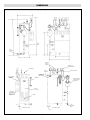
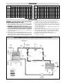
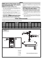
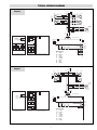
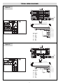
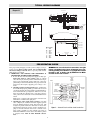
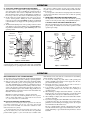
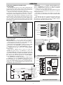
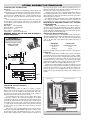
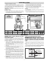
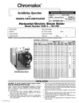
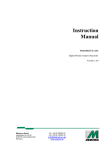
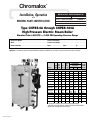
Chromalox
®
Installation, Operation
SERVICE REFERENCE
4
DIVISION
and
RENEWAL PARTS IDENTIFICATION
SALES
REFERENCE
SECTION
CHPES
PQ436-1
(Supersedes PQ436)
161-562802-002
MAY, 1999
DATE
Type CHPES-6A through CHPES-180A
High Pressure Electric Steam Boiler
Standard Trim is 250 PSI — 0-225 PSI Operating Pressure Range
Boiler Serial Number . . . . . . . . . . . . . . . . . . . . . . . . . . . . . . . . Power Circuit Voltage . . . . . . . . . . . . . . . . . . . . . . . . . . . . . . . . . .
Model . . . . . . . . . . . . . . . . . . . . . . . . . . . . . . . . . . . . . . . . . . . Control Circuit Voltage . . . . . . . . . . . . . . . . . . . . . . . . . . . . . . . . .
National Board No. . . . . . . . . . . . . . . . . . . . . . . . . . . . . . . . . . Amps . . . . . . . . . . . . . . . Phase . . . . . . . . . . . Cy . . . . . . . . . .
Important — This data file contains the National Board Registration Certificate for your boiler. It must be kept near the boiler at all times.
Model
3 Phase Voltages*
Output
Quantity/Rating
Elec
at
No./kW
of Contactors
Rating Cap. Vol. 212˚F
Heating
(BHP) (kW) (Gals.) (Lbs./Hr.) 208
240
480† Elements
Type CHPES — 20-250 PSIG
CHPES-6A
0.6
6
6
18
30
30
30
1-6
CHPES-9A
CHPES-12A
0.9
1.22
9
12
6
6
27
36.2
30
40
30
30
30
30
1-9
1-12
CHPES-18A
1.73
17
6
51.2
50
50
30
1-17
CHPES-24A
2.45
24
14.3
72.3
2-40
2-30
2-30
2-12
1-40
1-50
1-40
1-30
40
1-12
1-17
CHPES-30A
2.95
29
14.3
87.4
CHPES-36A
3.47
34
14.3
102.5
2-50
2-50
50
2-17
1-30
2-50
1-40
1-30
1-12
2-17
2-12
2-17
4-17
CHPES-48A
4.69
46
14.3
138.7
1-40
2-50
CHPES-60A
5.91
58
14.3
174.8
6.93
68
14.3
205
2-30
2-50
4-50
2-40
CHPES-72A
2-50
2-40
4-50
CHPES-100A 10.40
CHPES-135A 13.9
102
136
27.8
30.5
307
410
6-50
—
6-50
8-50
CHPES-160A 16.1 157.5
30.5
475
—
7-60
CHPES-180A 18.4
30.5
543
—
8-60
3-50
4-50
1-30
3-60
4-60
180
2-50
6-17
8-17
7-22.5
8-22.5
* Single phase available up to and including 24 kW capacity.
† All boilers must have separate 120V Control Circuit or Transformer.
Boilers under 40 Amps max are not fused.
© 2010 Chromalox, Inc.
DIMENSIONS
MODEL CHPES-6A through CHPES-180A
Check
Valve
Drain
Blowdown
Valve
Operating
Pressure
Controls
Manual Reset
High Limit Control
Steam Outlet
Control
Circuit Fuse
Safety Valve Outlet
Control Circuit
On/Off Switch
with Pilot Light
Pump Solenoid
Connection
Conduit Box
Sight Glass
McDonnell & Miller
Low Water Cutoff
Pump Control
Element
Access Door
Control Panel
Standard When
Three (3) or
More Contactors
are Used
Element
5/8"
Drain
Blowdown
Valve
1-1/4"
7/16" Bolt Hole Typical
7/16" Bolt Hole Typical
2
DIMENSIONS
Type CHPES — Dimensions (In.)
C D E F G H I
J
Model
A
B*
CHPES-6A
37 22-1/2 30 15-1/4 20 30-1/2 9-1/2
16
1/2
1
Type CHPES — Dimensions (In.)
C D E F G H I
J
K
L
CHPES-48A 43-1/2 26
46 17-1/2 23 34-1/2 16-1/2 24-1/2
1
1
1
3/4
3/4
K
L
Model
1/2
1/2
A
B*
CHPES-9A
37 22-1/2 30 15-1/4 20 30-1/2 9-1/2
16
1/2
1
1/2
1/2
CHPES-60A 43-1/2 26
46 17-1/2 23 34-1/2 16-1/2 24-1/2
1
1
1
CHPES-12A
37 22-1/2 30 15-1/4 20 30-1/2 9-1/2
16
1/2
1
1/2
1/2
CHPES-72A 43-1/2 26
46 17-1/2 23 34-1/2 16-1/2 24-1/2
1
1
1
3/4
CHPES-18A
37 22-1/2 30 15-1/4 20 30-1/2 9-1/2
16
1/2
1
1/2
1/2
CHPES-100A 63-1/2 30
55
1
3/4
21
27
36 16-3/4 37-1/2 1-1/2 1-1/4
CHPES-24A 43-1/2 26
46 17-1/2 23 34-1/2 16-1/2 24-1/2
1
1
1
3/4
CHPES-135A 63-1/2 32
55 20-1/2 26 37-1/2 16 37-1/2
2
1-1/4
1
3/4
CHPES-30A 43-1/2 26
46 17-1/2 23 34-1/2 16-1/2 24-1/2
1
1
1
3/4
CHPES-160A 63-1/2 32
55 20-1/2 26 37-1/2 16 37-1/2
2
1-1/4
1
3/4
CHPES-36A 43-1/2 26
46 17-1/2 23 34-1/2 16-1/2 24-1/2
1
1
1
3/4
CHPES-180A 63-1/2 32
55 20-1/2 26 37-1/2 16 37-1/2
2
1-1/4
1
3/4
*Add two inches for transformer.
INSTALLATION
water line valves open at all times except during blowdown.
5. All water feed systems are connected to water inlet check valve.
6. Connect steam line (with Globe valve) to boiler steam outlet.
Valve should be placed as close as possible to boiler outlet and
sized per label on boiler.
7. To insure maximum efficiency of supplied kW, all piping from
outlet should be insulated.
8. Drain and relief valve piping should be in accordance with state
and local codes. Floor drain to be provided directly below unit.
9. All electrical wiring should be done by licensed electrician in
accordance with national and local electrical codes.
10. If pump is located less than 30 feet from boiler, a second
check valve is required.
WARNING: To avoid electrical shock hazard, boilers
must be suitably grounded to earth.
1. The boiler should be mounted on a solid level foundation. Note:
When installing boiler, allow sufficient room (21” minimum) to
facilitate removal of elements if and when necessary.
2. WARNING: A minimum distance of 18” between boiler and any combustible material must be maintained.
3. Complete all piping to boiler. Connect water line to tagged fitting
on the motor and pump assembly, if used, or to tagged fitting on
water control feeder.
4. When any type of feed other than a pump feed is used — the existing water supply must be 10 pounds greater than the boiler operating pressure to assure water supply maintains proper water level in
boiler. Otherwise, lack of water can cause heater failure. Keep feed
Typical Plumbing Installation of a Steam Boiler with Condensate Return System
Insulated Steam Lines
(Pitch Down 5˚)
Safety
Valve
Globe
Valve
Heat
Exchanger
Water/Steam
Separator
Gate
Valve
(Typical
Load)
Trap
Trap
Vacuum
Breaker
Check
Valve
Check
Valve
Check
Valve
Return
Pitch Down 5˚
Cold Water
Make-Up
Vent
Boiler
Drain
Condensate
Return
Steam
Drain
Water
Strainer
Gate
Valve
Condensate
Vapor
Centrifugal
Turbine Pump
3
WIRING
damage. Industrial type lightning protectors should be installed per
manufacturer’s recommendations at your service entrance. Check
your contractor or electrical dealer for recommended type for your
system.
5. Be sure all electrical connections are sufficiently tightened.
6. WARNING: Substitution of components or modification of wiring system voids the warranty and may
lead to dangerous operating conditions.
7. SPECIAL INSTRUCTIONS FOR CUSTOMERS SUPPLYING THEIR OWN CONDENSATE OR PUMP SYSTEMS.
A. Check the voltage of the motor before making the wiring connection. Some Chromalox boilers are supplied with dual voltage systems. The motor should always match the voltage of the
control circuit.
B. The motor circuit should be wired into the pump control as
shown in wiring diagram (float type pump control). If boiler is
equipped with solid state pump control, refer to wiring diagram
and use terminals 5 and 2.
WARNING: Hazard of Shock. Disconnect all power
before working on boiler. Boilers must be effectively
grounded in accordance with the National Electrical
Code to eliminate shock hazard.
WARNING: Use 90˚copper conductors only.
1. Select proper wire gauge and type for supply conductors in accordance with the National Electrical Code and local wiring codes following wiring diagram supplied (See recommendations for disconnect switches and fusing).
2. The unit is completely wired and pre-tested before shipment. No
internal wiring is required. Check all electrical connections for
tightness and retighten if necessary before energizing.
If a separate control circuit is used, the control circuit should be
connected to the control terminal block, inside access door (not
required with transformer).
3. Safety Switches — WARNING: Purchaser should use a
safety switch employing circuit breakers or fuses
between his main power source and the boiler.
4. Because of their water lines, boilers are susceptible to lightning
TYPICAL WIRING DIAGRAMS
Use Applicable wiring diagrams based on model number and power voltage.
Boiler
CHPES-6A
CHPES-9A
CHPES-12A
CHPES-18A
CHPES-24A
208
1
1
1
1
2
3 Phase Voltage
240
480
1
1
1
1
1
1
1
1
2
3
Boiler
CHPES-30A
CHPES-36A
CHPES-48A
CHPES-60A
CHPES-72A
208
2
2
4
6
6
3 Phase Voltage
240
480
2
3
2
3
4
5
6
7
6
7
Boiler
CHPES-100A
CHPES-135A
CHPES-160A
CHPES-180A
Export
Diagram 1
L1 L2 L3
1 HTR
1
GND
1L1
C1
208
8
3 Phase Voltage
240
480
8
9
10
11
12
12
10
10
14
1
GND
FU1
1L2
FU2
1L3
FU3
CR
2L1
FU4
10L
IT1
2L2
FU5
20L
IT2
2L3
FU6
30L
IT3
Feed Water
Motor
1
Mtr
Feed Water
Electrical
Connection
1 2
1TB
Customer
Connect
3
GND
FU9
FU8
FU7
1PB
FU
1 2 3
H1
X1
3
GND
X3
H2
X2
Optional Transformer
X4
2
1
2
1
1
GND
B
FU9
B 1PB On
2
GND
Off
W
BR
IFS
R
Y
O
1
HTR
1LT
1PS
O
2PS
O
Boiler On
CR
Feed Water
C1
Heater
Contactors
C2
Cabinet Exterior Left Side
Panel Layout
C3
Cabinet Exterior Right Side
C4
Wire Color Code
B = Black
BR = Brown
R = Red
O = Orange
Y = Yellow
G = Green
BL = Blue
W = White
4
* Boilers under 40 Amps total (not fused)
TYPICAL WIRING DIAGRAMS
Diagram 2
L1 L2 L3
1 HTR
1L1
2
GND
2 HTR
C1
1L2
FU2
1L3
FU3
2L1
1
GND
FU1
C2
FU4
2L2
FU5
2L3
FU6
CR
3L1
FU7
10L
IT1
3L2
FU8
20L
IT2
3L3
FU9
30L
IT3
Feed Water
Motor
1
Mtr
Customer
Connect
FU11
2 GND
C1
FU
123
FU12
C2
FU
456
X1
1
H4
X3
X2
X4
2
2
1
B
FU12
B 1PB On
W
1LT
BR
IFS
Y
1PS
O
Cabinet Exterior Left Side
H2
Optional Transformer
3
GND
Off
1
HTR
H3
H1
1PB
1 GND
1TB
12
2TB
Feed Water
Electrical
Connection
3
GND
FU10
2PS
O
O
2
HTR
R
Boiler On
CR
Feed Water
C1
Heater
Contactors
C2
Wire Color Code
B = Black
BR = Brown
R = Red
O = Orange
Y = Yellow
G = Green
BL = Blue
W = White
Cabinet Exterior Right Side
Panel Layout
Diagram 3
L1 L2 L3
1 HTR
2
GND
2 HTR
1L1
C1
1
GND
FU1
1L2
FU2
1L3
FU3
2L1
2L2
2L3
CR
3L1
FU4
10L
IT1
3L2
FU5
20L
IT2
3L3
FU6
30L
IT3
Feed Water
Motor
1
Mtr
Customer
Connect
12
2TB
3 GND
FU7
1
X1
X3
X2
X4
2
2
2
HTR
Panel Layout
H4
B
FU9
B 1PB On
W
1LT
BR
IFS
R
Y
O
Cabinet Exterior Left Side
H2
1
Off
1
HTR
H3
Optional Transformer
3
GND
C1
FU
123
FU8
H1
1PB
2 GND
1 GND
Feed Water
Electrical
Connection
FU9
1PS
O
2PS
CR
O
C1
Boiler On
Feed Water
Heater
Contactor
Cabinet Exterior Right Side
Wire Color Code
B = Black
BR = Brown
R = Red
O = Orange
Y = Yellow
G = Green
BL = Blue
W = White
5
* Boilers under 40 Amps total (not fused)
TYPICAL WIRING DIAGRAMS
Diagram 4
1
GND
L1 L2 L3
1 HTR
2 HTR
C3
FU1
FU7
1L2
FU2
FU8
3L2
1L3
FU3
FU9
1L3
1L1
2
GND
C1
C2
2L1
3 HTR
3L1
FU4
2L2
FU5
2L3
FU6
CR
4L1
FU10
10L
IT1
4L2
FU11
20L
IT2
4L3
FU12
30L
IT3
Feed Water
Motor
1
Mtr
Customer
Connect
FU13
2 GND
3
GND
1TB
FU15
3
GND
C3
FU
1 2 3
FU
4 5 6
FU
7 8 9
Cabinet Exterior Left Side
2
2
1
B
FU15
B 1PB On
Off
W
1LT
BR
IFS
1PS
O
O
2PS
Boiler On
R
Y
3
Htr
1
HTR
X2 X4
X1 X3
1
1 GND
C2
H4
Optional Transformer
1PB
2 GND
C1
H3 H2
H1
12
2TB
Feed Water
Electrical
Connection
FU14
CR
Feed Water
C1
Heater
Contactor
O
C2
2
HTR
Cabinet Exterior Right Side
Panel Layout
Diagram 5
L1 L2 L3
1 HTR
1L1
C1
FU2
FU3
1L3
2 HTR
3 HTR
2L1
1
GND
FU1
1L2
2
GND
Heater
Contactor
C3
Wire Color Code
B = Black
BR = Brown
R = Red
O = Orange
Y = Yellow
G = Green
BL = Blue
W = White
C2
FU4
2L2
FU5
2L3
FU6
CR
3L1
4L1
FU7
10L
IT1
3L2
4L2
FU8
20L
IT2
3L3
4L3
FU9
30L
IT3
Feed Water
Motor
1
Mtr
Customer
Connect
FU10
1TB
C1
FU
123
C2
FU
456
1PB
3
GND
X1
1
X4
X2
2
2
W
1LT
BR
IFS
R
Y
O
1PS
O
2PS
O
Wire Color Code
B = Black
BR = Brown
R = Red
O = Orange
Y = Yellow
G = Green
BL = Blue
W = White
Cabinet Exterior Right Side
6
Boiler On
CR
Feed Water
C1
Heater
Contactors
C2
2
HTR
Panel Layout
X3
B
FU12
B 1PB On
3
HTR
Cabinet Exterior Left Side
H4
1
Off
1
HTR
FU11
H3 H2
Optional Transformer
FU12
1 GND
2 GND
12
2TB
Feed Water
Electrical
Connection
3
GND
H1
TYPICAL WIRING DIAGRAMS
Diagram 6
1
GND
L1 L2 L3
1 HTR
1L1
C1
1L2
2
GND
1L3
2 HTR
C2
FU1
FU7
FU2
FU8
FU3
FU9
3
GND
12
2TB
1TB
FU
123
C2
FU10
FU5
FU11
4L2
2L3
FU6
FU12
4L3
X1
3
GND
FU
456
FU
789
FU
10
11 12
FU13
10L
IT1
5L2
FU14
20L
IT2
5L3
FU15
30L
IT3
Cabinet Exterior Left Side
Feed Water
Motor
1
Mtr
Customer
Connect
FU17
H2
Optional Transformer
X3
X2
X4
2
2
B
FU18
B 1PB On
Off
W
1LT
BR
IFS
4
Htr
1
HTR
CR
5L1
1
C4
3
Htr
4 HTR
4L1
1
2 GND
C3
1L3
C4
1PB
1 GND
C1
3L2
FU4
H1
Feed Water
Electrical
Connection
3 HTR
3L1
2L2
2L1
FU16
FU18
C3
1PS
O
O
2PS
Boiler On
R
Y
O
CR
Feed Water
C1
Heater
Contactors
C2
2
HTR
Wire Color Code
B = Black
BR = Brown
R = Red
O = Orange
Y = Yellow
G = Green
BL = Blue
W = White
Cabinet Exterior Right Side
Panel Layout
C3
C4
1
GND
Diagram 7
L1 L2 L3
1 HTR
2
GND
3 HTR
C1
C2
FU1
FU4
1L2
FU2
FU5
2L2
1L3
FU3
FU6
2L3
1L1
2 HTR
2L1
3L1
4L1
3L2
4L2
4 HTR
4L3
3L3
CR
5L1
FU7
10L
IT1
5L2
FU8
20L
IT2
5L3
FU9
30L
IT3
Feed Water
Motor
1
Mtr
Feed Water
Electrical
Connection
2 GND
C1
FU
123
3
HTR
3
GND
1TB
C2
FU12
FU10
H1
H3
H2
X1
X3
X2
X4
Optional Transformer
1PB
1 GND
12
2TB
Customer
Connect
FU11
H4
3
GND
1
2
B
FU12
B 1PB On
4
HTR
Off
W
Cabinet Exterior Left Side
IFS
R
Y
2
HTR
Panel Layout
1LT
BR
O
1
HTR
2
1
FU
456
1PS
O
2PS
CR
O
C1
C2
Wire Color Code
B = Black
BR = Brown
R = Red
O = Orange
Y = Yellow
G = Green
BL = Blue
W = White
Cabinet Exterior Right Side
7
Boiler On
Feed Water
Heater
Contactors
TYPICAL WIRING DIAGRAMS
Diagram 8
L1 L2 L3
1L1
1L2
1L3
C1
2 HTR
2L1
2L2
2L3
C2
3 HTR
3L1
3L2
3L3
C3
FU7
FU8
FU9
4 HTR
4L1
4L2
4L3
C4
FU10
FU11
FU12
7L1
7L2
7L3
FU22
FU23
2
GND
1
GND
Feed Water
Electrical
Connection
1TB
C2
C3
FU
1 2 3
FU
4 5 6
FU
7 8 9
C4
C5
C6
FU
10
11 12
FU
13
14 15
FU
16
17 18
Cabinet Exterior Left Side
FU1
FU2
FU3
FU13
FU14
FU15
C5
5L1 5 HTR
5L2
5L3
FU4
FU16
C6
FU5
FU6
FU17
FU18
6L1 6 HTR
6L2
6L3
CR
FU19
FU20
IT1
10L
20L
30L
FU21
Optional Transformer
3
GND
3 GND
2
GND
X1
1
6
HTR
3
HTR
4
HTR
1
HTR
2
HTR
W
1LT
R
BR
IFS
Y
O 1PS
O
Cabinet Exterior Right Side
Panel Layout
2
2
B
FU24
1PB
On
B
Off
5
HTR
X4
X2
X3
1
FU1
FU2
FU3
C2
C3
FU
456
FU
789
Cabinet Exterior Left Side
Heater Contactor
C4
Heater Contactor
C5
Heater Contactor
C6
Heater Contactor
C3
FU7
FU8
FU9
5L1
5L2
5L3
5 HTR
6L1
6L2
6L3
6 HTR
CR
7L1
FU10
10L
IT1
7L2
FU11
20L
IT2
7L3
FU12
30L
IT3
FU13
Feed Water
Motor
1
Mtr
Customer
Connect
FU14
1PB
2TB
1 2
C2
FU
123
Heater Contactor
C3
FU4
FU15
1TB
Heater Contactor
C2
FU5
FU6
3L3
4 HTR 4L1
4L2
4L3
1 GND
C1
1
GND
2 HTR 2L1
2L2
2L3
3 HTR 3L1
3L2
CR
2PS
L1 L2 L3
C1
Boiler
On
Feed Water
3PS
O
Wire Color Code
B = Black
BR = Brown
R = Red
O = Orange
Y = Yellow
G = Green
BL = Blue
W = White
1 HTR 1L1
1L2
2
GND
1L3
C1
Feed Water
Motor
Customer
Connect
Diagram 9
Feed Water
Electrical
Connection
1
Mtr
IT2
IT3
1PB
FU24
2TB
1 2
C1
1
GND
1 HTR
H1 H3
H2 H4
3 GND
Optional Transformer
3
GND
2
GND
1
1
B
FU15
1PB
On
B
5
HTR
6
HTR
3
HTR
4
HTR
1
HTR
2
HTR
Panel Layout
2
X1 X3 X2 X4
Off
2
W
1LT
R
BR
IFS
Y
O
O 1PS
CR
O
Wire Color Code
B = Black
BR = Brown
R = Red
O = Orange
Y = Yellow
G = Green
BL = Blue
W = White
8
Feed Water
3PS
2PS
Cabinet Exterior Right Side
Boiler
On
C1
Heater Contactor
C2
Heater Contactor
C3
Heater Contactor
TYPICAL WIRING DIAGRAMS
L1 L2 L3
Diagram 10
1
GND
1 HTR
1L1
1L2
1L3
C1
FU1
FU2
FU3
FU13
FU14
FU15
C5
5L1 5 HTR
5L2
5L3
2 HTR
2L1
2L2
2L3
C2
FU4
FU16
C6
FU5
FU6
FU17
FU18
6L1 6 HTR
6L2
6L3
3 HTR
3L1
3L2
3L3
C3
FU7
FU8
FU9
FU13
FU20
FU21
C7
7L1 7 HTR
7L2
5L3
4 HTR
4L1
4L2
4L3
C4
FU10
FU22
C8
FU11
FU12
FU23
FU24
8L1 6 HTR
8L2
8L3
2
GND
9L1
9L2
FU25 CR
FU26
9L3
FU27
FU28
C5
C6
13
14 15
16
17 18
C7
19
20 21
C8
C2
1 2 3
4 5 6
C3
C4
7 8 9
10
11 12
Cabinet Exterior Left Side
1
H2 H4
X1
X2
X3
2
X4
3
HTR
4
HTR
W
1LT
R
BR
Off
IFS
Y
O 1PS
O
2
HTR
Panel Layout
2
B
FU30
1PB
On
B
8
HTR
6
HTR
1
HTR
Customer
Connect
1
5
HTR
Cabinet Exterior Right Side
CR
C1
2PS
C7
C8
FU1
FU2
FU3
C2
1
GND
C3
FU7
FU8
FU9
FU4
C4
FU10
FU11
FU12
FU5
FU6
3L3
4 HTR 4L1
4L2
4L3
FU13 CR
FU14
9L1
9L2
9L3
C1
FU
123
C2
FU
456
1PB
2TB
1 2
H1
C3
FU
789
C4
5 HTR
6L1
6L2
6L3
6 HTR
5L1
7L2
5L3
7 HTR
8L1
8L2
8L3
8 HTR
IT1
10L
20L
30L
IT2
IT3
H3
H2
X3
X2
1
Mtr
Feed Water
Motor
Customer
Connect
H4
Optional Transformer
3 GND
3
GND
2
GND
FU
10
11 12
X1
1
X4
2
1
7HTR
Cabinet Exterior Left Side
FU15
5L1
5L2
5L3
FU17
FU16
FU18
1TB
Heater Contactor
C5
2 HTR 2L1
2L2
2L3
1 GND
Heater Contactor
C6
C1
3 HTR 3L1
3L2
C2
C3
C4
L1 L2 L3
1 HTR 1L1
1L2
2
GND
1L3
Boiler
On
Feed Water
3PS
O
Wire Color Code
B = Black
BR = Brown
R = Red
O = Orange
Y = Yellow
G = Green
BL = Blue
W = White
Diagram 11
Feed Water
Electrical
Connection
6
HTR
3
HTR
4
HTR
1
HTR
2
HTR
Panel Layout
2
B
FU18
1PB
On
B
8
HTR
5
HTR
Feed Water
Motor
Optional Transformer
3
GND
2
GND
22
23 24
1
Mtr
IT2
IT3
FU29
H1 H3
1PB
FU30
3 GND
7
HTR
C1
1TB
2TB
1 2
1
GND
Feed Water
Electrical
Connection
IT1
10L
20L
30L
Off
W
IFS
Y
O
Wire Color Code
B = Black
BR = Brown
R = Red
O = Orange
Y = Yellow
G = Green
BL = Blue
W = White
Cabinet Exterior Right Side
9
1LT
R
BR
O 1PS
CR
O
Boiler
On
Feed Water
3PS
C1
C2
Heater Contactor
C3
Heater Contactor
2PS
C4
TYPICAL WIRING DIAGRAMS
Diagram 12
L1 L2 L3
1L1
1L2
1L3
C1
FU1
FU2
FU3
FU13
FU14
FU15
C5
5L1 5 HTR
5L2
5L3
2 HTR
2L1
2L2
2L3
C2
FU4
FU16
C6
FU5
FU6
FU17
FU18
6L1 6 HTR
6L2
6L3
3 HTR
3L1
3L2
3L3
C3
FU7
FU8
FU9
FU19
FU20
FU21
C7
7L1 7 HTR
7L2
5L3
4 HTR
4L1
4L2
4L3
C4
FU10
8L1
8L2
8L3
FU22 CR
FU23
2
GND
1TB
2TB
1 2
1
GND
Feed Water
Electrical
Connection
C5
C6
C7
3 GND
FU
13
14 15
FU
16
17 18
FU
19
20 21
2
GND
FU27
C2
C3
FU
FU
FU
1 2 3
4 5 6
7 8 9
C4
FU
10
11 12
Cabinet Exterior Left Side
FU11
FU12
FU25
H1
1PB
3
GND
FU24
IT1
10L
20L
30L
IT2
IT3
X2 X4
2
2
B
FU27
1PB
On
B
6
HTR
3
HTR
4
HTR
1
HTR
2
HTR
Off
W
1LT
R
BR
IFS
Y
O 1PS
O
Boiler
On
CR
Feed Water
C1
Heater Contactor
C2
Heater Contactor
3PS
O
Wire Color Code
B = Black
BR = Brown
R = Red
O = Orange
Y = Yellow
G = Green
BL = Blue
W = White
Cabinet Exterior Right Side
Panel Layout
Feed Water
Motor
Optional Transformer
1
5
HTR
1
Mtr
Customer
Connect
FU26
H4
H3 H2
X1 X3
1
7
HTR
C1
1
GND
1 HTR
C3
Heater Contactor
C4
Heater Contactor
C5
Heater Contactor
C6
Heater Contactor
C7
Heater Contactor
2PS
Diagram 13
L1 L2 L3
1 HTR
1L1
1L2
1L3
2 HTR
2L1
2L2
2L3
3 HTR
3L1
3L2
3L3
4 HTR
4L1
4L2
4L3
2
GND
C1
FU
1 2 3
C2
FU
4 5 6
1TB
2TB
1 2
1
GND
Feed Water
Electrical
Connection
C3
C4
FU
7 8 9
FU
10
11 12
FU18
FU1
FU2
FU3
1
GND
C3
FU7
FU8
FU9
5L1 5 HTR
5L2
5L3
6L1 6 HTR
6L2
6L3
C2
FU4
FU5
FU6
C4
FU10
FU11
FU12
8L1
8L2
FU13
FU14
8L3
FU15
7L1 7 HTR
7L2
5L3
CR
IT1
10L
20L
30L
FU16
H1 H2
3
GND
2
GND
X1 X3
1
X2 X4
Optional Transformer
2
1
4
HTR
1
HTR
2
HTR
Panel Layout
2
B
FU18
1PB
On
B
6
HTR
3
HTR
Feed Water
Motor
FU17
H3 H4
3 GND
5
HTR
1
Mtr
IT2
IT3
Customer
Connect
1PB
7
HTR
Cabinet Exterior Left Side
C1
Off
W
IFS
Y
O
Wire Color Code
B = Black
BR = Brown
R = Red
O = Orange
Y = Yellow
G = Green
BL = Blue
W = White
Cabinet Exterior Right Side
10
1LT
R
BR
O 1PS
O
Boiler
On
CR
Feed Water
C1
Heater Contactor
C2
Heater Contactor
3PS
C3
Heater Contactor
C4
Heater Contactor
2PS
TYPICAL WIRING DIAGRAMS
Diagram 14
346V 3Ø 50 HZ
L1 L2 L3
1 HTR
2 HTR
2
GND
1 2
2TB
Feed Water
Electrical
Connection
C1
C2
C3
C4
FU
1 2 3
FU
4 5 6
FU
7 8 9
FU
10
11 12
1TB
2
GND
3
GND
FU16
1
GND
1L1
1L2
1L3
C1
FU1
FU2
FU3
FU7
FU8
FU9
C3
3L1 3 HTR
3L2
3L3
2L1
2L2
2L3
C2
FU4
FU5
FU6
FU10
FU11
FU12
C4
4L1 4 HTR
4L2
4L3
5L1
5L2
5L3
FU13 CR
FU14
1PB
1CR
FU15
IT1
10L
20L
30L
IT2
IT3
1
Mtr
Feed Water
Motor
Customer
Connect
1
GND
220 VAC Single Phase Control Circuit
3
GND
3
HTR
4
HTR
1
HTR
2
HTR
1
2
B
FU16
1PB
On
B
Off
Cabinet Exterior Left Side
Panel Layout
W
BR
IFS
Y
Cabinet Exterior Right Side
O
Wire Color Code
B = Black
BR = Brown
R = Red
O = Orange
Y = Yellow
G = Green
BL = Blue
W = White
1PS
O
1CR-1
B
1LT
R
1
CR
Boiler
On
C1
Heater Contactor
C2
Heater Contactor
9.9
2PS
Customer Pump
Connection
C3
Heater Contactor
C4
Heater Contactor
1CR-2
W
PRE-OPERATION CHECK
After proper wiring and piping of boiler system is complete, testing of
controls can start. Before testing controls, it is recommended that
all contactor fusing be removed. This is to prevent possible element
failure under test conditions.
A. OPERATING AND TESTING THE McDONNELL &
MILLER LOW WATER CUTOFF CONTROL.
1. Be sure all valves from incoming water supply are fully open.
Turn boiler switch to “ON” position, pump or solenoid
valve will energize, allowing boiler to fill with water. Proper
water level is automatically reached with level control supplied. Pump or solenoid feed will shut off at proper water level.
Contactor(s) will energize, supplying power voltage to elements.
2. Checking operation of pump switch. (Figure 1) With water
level visible in sight glass, partially open drain valve at bottom
of boiler. If automatic blowdown supplied, push manual blowdown switch until valve open light is on, hold for few seconds.
Water level will fall, allowing float to trip pump switch to
“ON” position. Close drain valve or release manual blowdown
switch.
Pump motor or solenoid valve will energize and water level
will resume to normal level in sight glass.
3. Checking low water cutout switch operation, open drain
valve completely. If automatic blowdown supplied, push in
and hold manual blowdown switch until water level falls
enough to trip cutout switch. Close drain valve or release manual blowdown switch. If low water cutout is automatic reset,
pump or solenoid will return water level to normal. If low
water cutout is manual reset, then manual reset button on
McDonnell & Miller low water cutoff control must be pushed
to complete circuit. Turn off boiler. Reinstall contactor
fuses.
WARNING: Be sure all electrical connections are tight
before energizing boiler. Reset all manual reset controls by pushing reset buttons on: (1) high limit control
located on top of boiler and (2) McDonnell & Miller
located on the side of boiler.
Cut-off
and
Alarm
Switch
Pump
Low-Water
Cut-Off
Terminals
B
C
D
Adjusting
Screws
A
Alarm
Circuit
Terminals
Pump
Circuit
Terminals
Pump
Switch
Line
Figure 1 — Automatic Reset Low-Water Cutoff Junction Box
11
OPERATION
allow pressure to build up. When pressure gauge reading approaches
set point of pressure control, the switch will trip and shut off boiler.
Turn off boiler.
To reset pressure control, bleed off enough pressure in the boiler by
opening steam outlet drain, or blowdown valve to allow the operating
control to reset.
4. HIGH LIMIT PRESSURE CONTROL OPERATION
The high limit is tested in the same manner but with the operating
control set above the pressure setting of the high limit. (Figure 3)
CAUTION: THIS IS FOR TEST PURPOSES ONLY!
When the high limit trips, turn off boiler and reset high limit to
proper setting. The manual reset level must be pushed to resume
operation upon startup.
B. ADJUSTING OPERATING PRESSURE CONTROLS
1. Chromalox boilers are supplied with operating and high limit pressure controls. One is used for controlling the operating pressure of
the boiler while the other is used as a high limit control. To determine the difference in the controls, the high limit has a manual reset
lever on top of the case. Also, there is no differential scale present.
2. On all controls, the pressure adjusting screw on the top of the case
sets the desired pressure. Turning the screw counterclockwise
reduces the pressure setting (CUT OUT) (See Figure 2). High limit
control should be set at 10 psig above the operating pressure of the
boiler.
3. The differential adjusting screw on the operating control is set in the
same manner as the pressure adjusting screw. The CUT OUT setting minus the differential setting, equals CUT IN pressure of the
operating control.
Differential
Adjusting Screw
Pressure
Adjusting
Screw
Pressure
Adjusting
Screw
Mercury
Switch
Manual
Reset
Lever
Scaleplates
Differential
Setting
Indicator
Scaleplates
Pressure
Setting
Indicator
Pressure
Setting
Indicator
Operating
Lever
Diaphragm
Assembly
Pointer
Index
Mark
Operating
Lever
Leveling
Indicator
Diaphragm
Assembly
Figure 2 — Pressure Control
To check operation of the controls, close steam outlet valve and adjust
operating pressure control to a low pressure setting. Also, set high limit
control at 10 psig above operating pressure control. Turn on boiler, and
Leveling
Indicator
Mercury
Switch
Index
Mark
Pointer
Figure 3 — Hi Limit Control
OPERATION
than mineral content, take this into consideration in determining
which schedule is to be followed.
1. At end of the working day, while boiler is still operating, turn
switch to the OFF position and close water supply valve. De-energize wall mounted safety switch.
2. If blowing-down into a receptacle, allow pressure to decrease to
15-20 psi before opening blowdown valve.
3. It is preferable to connect the blowdown valve directly into a
drainage system. If this is done, the boiler can be discharged at
operating pressure.
4. When discharge is complete and boiler is drained — (a) close the
blowdown valve; (b) open water supply valve; (c) put boiler switch
in the ON position; and, (d) close wall mounted safety switch.
5. When refilling is complete, turn off the boiler switch unless further
operation is desirable.
6. If you have been supplied with a Manual Reset Low Water control
as required in some states, the reset button on the control must be
pushed before boiler will begin developing pressure. (Do not push
reset until boiler has filled with water.)
The use of chemical boiler cleaning compounds in these boilers
voids all warranties unless approved by manufacturer. Some compounds will damage copper sheathed heating elements to shorten
useful life.
RECOMMENDED START-UP PROCEDURES
1. Close globe valve on steam outlet side of boiler. (Customer Supplied)
2. Turn on boiler and allow pressure to build up to operating pressure.
3. Only open globe valve at quarter turns at first, introducing smaller
amounts of steam into process. Avoid opening globe valve all at
once. This will eliminate the possibility of evacuating the boiler of
water caused by the suddenly increased boiling of the water in the
vessel as the pressure is reduced. On boilers where constant pressure is not maintained, globe valve should be kept partially closed.
This will maintain a constant head on the boiler and stabilize any
fluctuation in boiler water level.
Note: For best boiler performance, a 1/4” less steam valve
than size of safety valve should be plumbed as close as practicable to steam outlet. Where 1/2” safety valve is used on boiler, a 1/4” steam valve is recommended.
MANUAL BLOWDOWN INSTRUCTIONS
Blowdown is an essential part of boiler operation. It is the best
preventative maintenance you can give your boiler and will add
years of life to the unit. Make sure a blowdown schedule is established and followed regularly.
In extremely hard water areas, blowdown is necessary once a
day. In soft water areas, once each week. If there is a particular
problem which applies to your own local water condition other
12
OPERATION
OPERATION— Set the “BOILER PROGRAMMED DUTY”
switch to “BOILER ON” if the boiler is to be shut down each night.
Set it to “24-HOUR DUTY” if the boiler is to remain on continuously 24-hours per day (except during blowdown).
Set the tabs on the large timer for the ON and OFF times desired
for the boiler, screw in the small black day-skip tabs if is to remain off
during the weekend, etc.
If the boiler is on 24-hour duty, set the OFF tab for the time that is
desired for blowdown. Tzhe ON tab can be ignored, but must remain
on timer.
The small time delay relay controls the time that the drain valve
remains open. The time is controlled by adjusting knob marked
Blowdown cycle. Counterclockwise decreases, clockwise increases
blowdown time. Time must be adjusted by trial.
AUTOMATIC BLOWDOWN INSTRUCTIONS
(IF FURNISHED)
The Automatic Blowdown is a device which automatically starts
up your boiler in the morning; shuts it down at night and blows down
(partially drains) the main boiler drain and the low water cut-off column for a predetermined time interval each working day.
The heart of the unit is an electrically operated straight through
type ball valve. It is specially designed to handle dirty, corrosive fluids and particles without requiring cleaning or the use of a strainer.
Both the valve and the boiler are controlled by an electric control
unit which indicates with pilot lights when the drain valve is in the
opened or closed position and when the boiler is ON or OFF. In addition to the automatic control function, the unit has a push button which
momentarily de-energizes the boiler and opens the drain valve regardless of the time of day.
Timer
Boiler On
Valve Open
Valve Closed
Programmed Duty
24 Hour Duty
Manual Drain
Automatic Blowdown Control Cabinet
The unit may also be used to blow down boilers which run continuously, day and night.
INITIAL TESTING — Set the switch marked “Programmed
duty/24 Hour duty” located on the panel box to the “ON” position.
On the large timer set the “ON” tab at about 8 AM and the “OFF”
tab at about 8 PM. Set the blowdown cycle dial at “O”.
Turn the large timer by hand until the “ON” tab passes the “TIME
NOW” indicator so the “TIME NOW” arrow indicates 10 AM.
Energize the main feed to the “LINE TERMINALS” of the unit.
The “BOILER ON” pilot light as well as the “VALVE CLOSED”
light should glow.
Hold down the “DRAIN” button for about six seconds. The
“BOILER ON” light should go out immediately as well as the
“VALVE CLOSED” light. It takes about 4 seconds for the drain valve
to open fully at which time the “DRAIN VALVE OPEN” light should
light. As soon as the “DRAIN” button is released the valve begins to
close. When it reaches the closed position, the “VALVE CLOSED”
and the “BOILER ON” should light up again.
Now turn the wheel on the large timer until the “OFF” tab passes
the “TIME NOW” arrow. The “BOILER ON” light should go out and
the valve should begin to open. Once the “VALVE OPEN” light goes
on, the valve should remain open for a few seconds and then automatically close. The “VALVE CLOSED” light should light and the
“BOILER ON” light should remain off.
Valve Actuator
Display View of Automatic Blowdown Control Cabinet
Cycle
Adjustment
Blowdown Cycle
30's
0's
80's
Boiler On
Support
On/Off Switch
Valve Closed
Indicator Light
Terminal Block
7 Day Clock
Valve Open
2
3
1FU
15A
w
Clock
3
A
B
1CL
2
1CL 4
1PB
3
P
PR
1CR
6
1
2
1TR
2B
8
Ball Valve
Control
(5)
Boiler On
R
Y
R
Switch
24 Hour Duty
2LT
O/R
8
W
2
Valve Closed
R
Control
Relay
Time Delay Relay
PB Switch
Boiler Control
(3)
1CR
4
7
1TR
1LT
B
Motorized
2PB
2A
1
G
Support
Prorammed Duty
7-Day Timer
(2.3)
1
1
Indicator Light
Manual Drain
3 2
Fuse
Replace with
Amp Fuse Only
Exterior Side
6 2 10 2 7 11 8
Terminal Block
Component Layout
2
3
BL
1A
M
10
B
O/BL
11
Blowdown Valve
0
3LT
Valve Open
R
1B
Wiring Diagram for Automatic Blowdown
13
OPTIONAL EQUIPMENT FOR STEAM BOILERS
the motor runs, the wiper on the feedback potentiometer moves in a
direction to balance the circuit. When the circuit is again in balance, the
balancing relay contacts open and the motor stops.
Similarly if the pressure of the controlled medium falls, the wiper on
the controller potentiometer moves toward B, and the “open” contacts
in the balancing relay make. The motor drives towards its open position
until circuit balance is achieved.
The slightest change in the pressure of the controlled medium will
cause a change in the number of elements energized to compensate for
it, thus keeping the pressure constant. This process is called modulation.
PROPORTIONAL PRESSURE CONTROL ONLY SUPPLIED
WITH SEQUENCER
Main Setting — Turn the adjustment screw until the indicator is
opposite the low point of the desired throttling range. That is, if the pressure is to be held at a minimum of 50 psi, set the indicator at 50 psi. The
pressure will them be maintained between 50 psi and a higher pressure
equal to the 50 psi plus the throttling range.
THROTTLING RANGE SETTING L91B
After setting the indicator for the minimum pressure, turn the throttling range adjustment screw until the throttling range indicator points to
the desired throttling range on the scale. This scale is graduated from
“min” to “F”. The value of each division varies with the scale range of
the instrument.
AUXILIARY LOW WATER CUTOFF
Operation
Operation of this control is accomplished by sensing a minute AC
current flowing between submerged contact probe in the boiler shell.
When this minute AC current is conducted through an external circuit resistance up to 40,000 ohms or less, a signal of sufficient magnitude is present to trigger the SCR and, in turn energize the control
relay.
As the water level in the boiler drops below the level of the probe,
the AC current is broken and the control relay is de-energized. The
control will not energize until sufficient water is present in the boiler.
Specifications
Input Supply — 120 vac/50-60 hz
Detectable Range — 100,000 ohms
Probe Voltage — 24 Vac
Probe Current — 10 milliamps
Control Relay — Single pole double throw
WARNING: Control will not work with de-ionized or
demineralized water.
Typical Wiring for
Auxiliary Low Water Cutoff
Electronic Resistance Sensing
Amplifier for Auxiliary
Low Water Cutoff
PRESSURE
SCALE RATING
0-15 psi
20-300 psi
480V
3
60 HZ
L1 L2 L3
C1
1 HTR
FU
FU
Fuses Supplied
on Boilers Rated
Over 40 Amps.
3
GND
Pressure scale rating will vary depending on pressure control supplied.
CHECKOUT
After the controller has been installed, wired, and set, it should be
tested with the system in operation. First allow the system to stabilize.
Then observe the operation of the controller while raising and lowering
its set point. Pressure should increase when the set point is raised and
decrease when the set point is lowered. Use accurate pressure testing
equipment when checking out the controller. Do not rely on inexpensive
gauges. The controllers are carefully calibrated at the factory.
If the motor or actuator runs the proper direction when the set point
is adjusted, it can be assumed that the controller is operating properly. If
it runs in the wrong direction, reverse the B and W wires. Observe the
action of the motor to see if it stabilizes. If the motor is moving constantly, widen the proportioning range a little at a time, until the system
is stable.
1
GND
FU
2
GND
FU2
FU1
H1 H3 H2
1
H4
480V/120V
1.5 KVA
2
X1 X3 X2 X4
2
1
B
FU3
B 1PB On
W
1LT
BR
Boiler On
R
Off
3
3
6
6
Auto
Blow
Down
System
2
2
2
2
1PS
W
W
Y
O
1PS
O
O
LWCO Probe
L1 L2
BL 2PS
C1 NO
R H
C
Aux. Low
Water Cutoff
VALUE EACH
DIVISION ON SCALE
2.2 psi
16.4 psi
Feed Water
(Solenoid Pump)
W
BL
C1
Heater
Contactor
Adjusting Screw
PROPORTIONING PRESSURE CONTROL FOR
SEQUENCER AND SCR CONTROLS
Typical Operation
Pressure variations cause the bellows to expand or contract.
Linkage between the bellows and the potentiometer wiper causes the
wiper to move across the windings on the potentiometer. This varies
the resistance between R and B, and between R and W, causing an
unbalance in the circuit connected to the controller.
A proportioning pressure control is used to regulate a motor driven
or solid state sequencer. The controller potentiometer, the feedback
potentiometer in the motor and a balancing relay in the motor form an
electric bridge circuit. As long as the pressure of the controlled medium remains at the set point of the controller, the circuit is balanced;
i.e., equal currents flow through both sides of the balancing relay and
the relay contacts are open. When the circuit is balanced, the motor
does not run.
If the pressure of the controlled medium rises, the wiper in the controller moves toward W. This unbalances the circuit so a larger current
flows through one side of the balancing relay. The “close” contacts in
the relay make, causing the motor to drive toward its closed position. As
Differential Adjusting Screw
R
W
B
(L91B) Proportioning Pressure Control used with Sequencer Control
14
OPTIONAL EQUIPMENT FOR STEAM BOILERS
IF A CONTROLLER SEEMS TO OPERATE IMPROPERLY
If the controller is suspected of operating improperly, it may be
further checked as follows:
1. Leave the controller installed where it is, but disconnect all power
to the boiler.
2. Loosen the cover screw below the main scaleplate and remove the
cover.
3. Disconnect the wires from the controller.
4. Connect an ohmmeter between controller terminals B and W to
measure the resistance of the potentiometer in the controller. The
ohmmeter should read about 135 ohms on an L91B.
5. Connect the ohmmeter between controller terminals W and R and
raise the set point of the controller above the actual pressure being
measured. The ohmmeter should read the full value of the potentiometer measured in step 4 (135 ohms for an L91B).
6. Slowly lower the set point of the controller while observing the
ohmmeter reading. The resistance should drop to zero at some set
point below the actual pressure.
7. An approximation of the proportioning range can be made by
observing the change in set point required for a resistance change
from zero to full value.
8. When the controller is operating properly, reconnect the wires,
replace the cover, tighten the cover screw, and reset the controller
to the desired value.
9. Reconnect power to the controlled motor.
Main Scale
Adjusting
Screw
Sequencer (5-Step)
TESTING OPERATION OF SEQUENCER
1. With boiler off, remove wiring from pressure control on
sequencer low voltage terminal board.
2. Turn on boiler to supply the voltage to the sequencer. Short terminal R and B for counterclockwise rotation and terminal R and
W for clockwise rotation.
3. If sequencer operates under this test procedure, but when rewired
to pressure controller and does not function, check pressure control. Note that wiring is W-B and B-W-R-R between sequencer
and pressure controller
BOILER SEQUENCE — SOLID STATE
Solid State Progressive Sequencer
The solid state progressive sequencer provides accurate electronic control of multi-stage loads of the type used in Chromalox
steam boilers. It features progressive sequencing (first on-first off)
which equalizes the operating time of each load. This control gives
visual indication of each energized stage by means of integral solid
state light emitting diodes. In the event of power interruption, all
heating elements are immediately de-energized for safety. When
power resumes, the control will restage the loads one at a time.
The solid state sequencer operates on 120V AC/60 Hz and each
output is relay switched with a load rating of 125 VA at 120V AC.
The input to the sequencer is a 0-135 OHM potentiometer supplied on the operating pressure control. The sequencer has a sensitivity control which is adjustable from min. to max. This sensitivity
control defines the amount of resistance (pressure) deviation
allowed before adding or subtracting a load. Potentiometer resistance should decrease with increasing pressure. Connections are
made to red and white terminals of proportional pressure control.
See Wiring Diagram 337-300164-452 for Boiler With Solid State
Sequencer.
Proportioning Range
Adjusting Screw
R
W
B
Main Scale
Setting
Indicator
Ohmmeter
Set Point
Increase
W
R
B
Increases to
135 Ohms
Terminals are not Labeled, but Screw-Heads are
Color Coded Red (R), White (W) and Blue (B).
BOILER SEQUENCER (5 STEP) MOTOR DRIVEN
RECYCLE FEATURE
The step control is designed to drop out all contactors when control circuit is interrupted. On resumption of power, the camshaft
rotates to the counterclockwise (ccw) limit, opening all the load
switches. The recycle relay then energizes, pulling in the load contact, and finally the camshaft rotates clockwise (cw) to the position
called for by the pressure controller energizing, in sequence, the
required load stages.
Solid State Sequencer
15
OPTIONAL EQUIPMENT FOR STEAM BOILERS
480V 3Ø 60 HZ
L1 L2 L3
CR
10L
IT1
20L
IT2
30L
IT3
Feed Water
Motor
1
Mtr
Optional Transformer
Customer
Connect
W
Boiler
On
Auto
Blowdown
System
Sequencer
Wire Color Code
B = Black
BR = Brown
R = Red
O = Orange
Y = Yellow
G = Green
BL = Blue
W = White
Pressure
Control
CR
Feed Water
Solenoid Valve
Heater Contactor
Heater Contactor
480/120V
Heater Contactor
5 Step
Control
Heater Contactor
Typical wiring for boilers equipped with Auto Blowdown System and/or Solid State Sequencer
WATER FEED SYSTEMS
1. Locate feed on level floor or platform.
2. Connect water line to tagged fitting on feed.
3. Connect piping from discharge to water inlet check valve on boiler with minimum of 90˚ bends or other restrictions.
4. All electrical wiring should be done by licensed electricians in
accordance with local and national electrical codes. Refer to boiler instruction for manual wiring diagram.
5. If pump is located less than 30 feet from boiler, a second check
valve is required.
HIGH PRESSURE FEED
High pressure makeup water pumps are used when water pressure
does not exceed boiler pressure by more than 10 psi and when condensate water is not returned to the boiler. Note: Consult factory or
sales office for motor/pump sizing for appropriate water feed system.
Installation
WARNING: Hazard of Electric Shock. Water feed system
must be effectively grounded in accordance with the
National Electrical Codes to eliminate shock hazard.
Automatic High Pressure Water Feed Pump/Motor Assembly
Pump Motor Dimensions
Assembly
Model
ES-38020
HP
3/4
Pipe
Pressure Size
Range (NPT) A
0-200
1/2 16-1/4
16
Dimensions (In.)
B
3
C
D
E
F
7-3/16 4-7/8 6-1/2 6-1/8
WATER FEED SYSTEMS
B. The motor circuit should be wired into the pump control located on
the boiler. See boiler instruction sheet for wiring diagram.
C. All electrical wiring should be done by licensed electrician.
D. Be sure to use the proper wire. Electrical wiring to boiler
should be in accordance with National Electrical Code or local
wiring code following wiring diagram supplied.
Plumbing
A. Connect water line to tagged fitting on the motor and pump assembly control feeder.
B. Interconnecting piping between boiler and condensate return system
should be installed with a minimum of 90˚ bends or other restrictions.
CONDENSATE RETURN SYSTEMS
Chromalox condensate return systems are used wherever condensed
steam can be collected for reuse in the boiler. Significant energy can be
saved by returning condensate to the boiler. The condensed water is free
from corroding minerals and carries a substantial amount of heat which
does not have to be replenished.
IMPORTANT: Vacuum breaker is required whenever using a condensate return system.
Installation — Wiring
A. Check the voltage of the motor before making the wiring connection.
Some Chromalox boilers are supplied with dual voltage systems. The
motor should always match the voltage of the control circuit.
1-1/4” NPT Vent
30 Gal.
Condensate
Return System
L
Return Inlet
Make-Up Valve
Inlet
1-1/4” NPT
3” NPT
Discharge
H
1” NPT
Drain
W
Condensate
Model
For Boiler Model
Max. Pressure (psig)
Storage Tank
Capacity (Gals.)
Pump (Hp)
Motor (Volts/Phase)
Pump Discharge
Conn. (NPT)
Condensate
Ref. Conn. (NPT)
HPCS3003
All CHPES
250
30
3
240 / 480 1
1-1/4
2
Dimensions (In.)
L
H
W
36
42-3/16
24
MAINTENANCE
INSTRUCTIONS FOR ELEMENT REPLACEMENT
WARNING: Before installing your new elements, be sure
the McDonnell-Miller low-water cut-off is operating
perfectly and the float chamber and lower equalizer
column are completely clear of sludge or other foreign
matter.
Failure to do this may cause the immediate burnout of the new elements.
All elements are thoroughly checked before shipment. The manufacturer cannot be responsible for burnouts caused by a faulty low-water
cut-off.
The lower equalizer column can best be examined by breaking the
unions on either side and then visually and manually examining the piping with your fingers or probes to see if it is clear and clean.
WARNING: Hazard of Shock. Disconnect all power
before working on boiler.
Chromalox Electric Steam Boilers are designed for years of trouble-free
performance. To establish a good preventative maintenance program,
we suggest the building maintenance man or engineer familiarize himself with these simple rules:
1. The use of specific boiler cleaning compounds cannot be recommended. We do recommend that a reputable firm of water treatment engineers be consulted regarding conditioning boiler water.
Proper selection must be made of a compound to prevent damage to
copper sheath heating elements.
2. The sight glass should be checked daily to ensure the boiler has adequate water.
3. A monthly inspection should be made of internal wiring. All electrical connections should be checked for tightness.
A check for water or steam leaks should also be made and any loose
fittings immediately tightened.
4. If boiler is equipped with Solid State Auxiliary Low Water Cutoff,
every four months the probe should be checked for deposits and
cleaned, if necessary. This is accomplished by removing inspection
plate, removing the probe (with a standard sparkplug wrench) cleaning and replacing.
Note: The system will not operate if the boiler is using distilled,
demineralized or deionized water. At the same time, one of the bottom heating elements should be removed. If scale has begun to form,
all elements should be cleaned and boiler drained and flushed.
5. IMPORTANT: The Manufacturers’ Data Report enclosed
within the instruction sheet is very important and must be put in a
safe place. You may be called upon to produce it by a state agency.
Boiler
1-1/2"
1" Steam Equalizing Pipe
Pump and Low
Water Control
Normal Boiler
Water Level
Cutoff Level
is Arrow Mark
Blowdown
Valve
1" Water Equalizing Pipe
17
MAINTENANCE
7. When all (6) flange bolts are tight, connect all wires to terminals.
Make certain wires are clean and bright to assure good electrical
contact and nuts on screws are firmly secured.
WARNING: Avoid use of chemical cleaning compounds. Follow maintenance instructions.
8. Open water valve so water supply can reach boiler feed mechanism.
9. Put main safety switch to “on” position.
10. Turn boiler to “on” position.
11. As boiler automatically refills, observe the new flange assemble
for possible leaks. If water is noticed, to bolts must be retightened.
Before doing this, turn the boiler off at the main fuse safety switch.
12. As boiler is heated to working pressure, check flange assembly
again for leaks.
WARNING: Avoid the use of chemical cleaning compounds. Follow maintenance instructions
READ COMPLETELY BEFORE STARTING WORK
1. Disconnect boiler from electric power supply at main safety
switch or fuse panel. Then, turn boiler switch to “off” position.
2. On automatic feed units, close valve on incoming water line. Drain
boiler completely of water.
3. Open boiler door to expose heating element.
4. Disconnect wire (electric) leads connecting element to main power
system of boiler. Again note wire connections to facilitate
reassembly. Proceed to remove (6) 5/16-18 bolts from flange.
5. Thoroughly clean boiler flange of all foreign material. Be certain
no part of old gasket remains on boiler flange.
6. Apply “Slic-Tite” Gasket Compound or equal to both surfaces of
new gasket with supplied replacement element. Proceed to install
element flange assembly with gasket between boiler flange and
element flange. In doing this, be careful to align flange holes so
wire connection terminals on element assembly are in line with
previously disconnected wire leads to facilitate easy connections.
RENEWAL PARTS IDENTIFICATION
Safety Valve
Operating Pressure Control
Range 10-300 Psi
Manual Reset High
Limit Control
Steam Outlet
Pressure Gauge, 0-600 Psi
On/Off Switch and
Pilot Light
Water Level Sight Glass
McDonnell & Miller #194
Low Water Cutoff/Pump
Check Valve/Water Inlet
(not shown)
Drain Blowdown Valve
Drain Blowdown Valve
18
RENEWAL PARTS IDENTIFICATION
Part Description
Part Number
Part Description
1/4” Ball Valve (Pressure Gauge) . . . . . . . . . . . . . . . . . . . . . . . .
Blowdown Valve 1” CHPES-24A
through 180A . . . . . . . . . . . . . . . . . . . . . . . . . . . . . . . . . . . . .
Pressure Gauge 3-1/2” 0-600 psi CHPES-100A
344-121194-007
130-118661-012
Operating Pressure Control . . . . . . . . . . . . . . . . . . . . . . . . . . . .
Hi-Limit Control (Manual Reset) 15 psi . . . . . . . . . . . . . . . . . . .
Proportional Pressure Control . . . . . . . . . . . . . . . . . . . . . . . . . .
5-Step Motor-Driven Sequencer . . . . . . . . . . . . . . . . . . . . . . . .
10-Step Motor-Driven Sequencer . . . . . . . . . . . . . . . . . . . . . . .
6-Step Solid State Sequencer . . . . . . . . . . . . . . . . . . . . . . . . . .
10-Step Solid State Sequencer . . . . . . . . . . . . . . . . . . . . . . . . .
Siphon Tube for Pressure Controls . . . . . . . . . . . . . . . . . . . . . .
072-122686-003
072-122686-006
072-122686-009
MM-94 Control Complete (Auto Reset) . . . . . . . . . . . . . . . . . . .
MM-94M Control Complete (Manual Reset) . . . . . . . . . . . . . . .
344-121194-042
CONTACTORS
through 180A . . . . . . . . . . . . . . . . . . . . . . . . . . . . . . . . . . . . .
Fusible Contactors
30 amp with 35-60 amp 600V block . . . . . . . . . . . . . . . . . . . . .
40 amp with 35-60 amp 600V block . . . . . . . . . . . . . . . . . . . . .
50 amp with 35-60 amp 600V block . . . . . . . . . . . . . . . . . . . . .
Non Fusible Contactors
60 amp without fuse block . . . . . . . . . . . . . . . . . . . . . . . . . . . . .
50 amp without fuse block . . . . . . . . . . . . . . . . . . . . . . . . . . . . .
1KVA 208V Primary . . . . . . . . . . . . . . . . . . . . . . . . . . . . . . . . . .
1KVA 240/480V Primary . . . . . . . . . . . . . . . . . . . . . . . . . . . . . .
1-1/2 KVA 208V Primary . . . . . . . . . . . . . . . . . . . . . . . . . . . . . .
1-1/2 KVA 240/480V Primary . . . . . . . . . . . . . . . . . . . . . . . . . . .
072-047913-012
072-047913-020
128-123459-012
128-123459-013
128-123459-014
128-123459-015
128-123459-016
129-047445-002
303-071809-032
303-071809-012
226-300177-009
226-300173-011
193-121843-020
351-118664-001
355-300174-001
344-121780-002
CONDENSATE RETURN SYSTEMS
Hose Assembly 18” Long used in EES-38020 HP . . . . . . . . . . . . .
Fuse . . . . . . . . . . . . . . . . . . . . . . . . . . . . . . . . . . . . . . . . . . . . . .
Overload . . . . . . . . . . . . . . . . . . . . . . . . . . . . . . . . . . . . . . . . . . .
Condensate Return System . . . . . . . . . . . . . . . . . . . . . . . . . . . .
303-071809-014
303-071809-016
349-300181-002
128-121133-053
359-122688-031
296-300222-026
AUX LOW WATER CUT-OFF (OPTIONAL EQUIPMENT)
155-554735-004
155-554735-009
155-554735-006
155-554735-011
Pump/Motor . . . . . . . . . . . . . . . . . . . . . . . . . . . . . . . . . . . . . . . .
Probe Spark Plug . . . . . . . . . . . . . . . . . . . . . . . . . . . . . . . . . . . .
Aux Low Water Cut-off Board with Relay . . . . . . . . . . . . . . . . . .
Aux Low Water Cut-off Board Without Relay . . . . . . . . . . . . . . .
Relay for Aux Low Cut-off Board . . . . . . . . . . . . . . . . . . . . . . . .
Probe 7-15/16” CHPES 6A through 18A . . . . . . . . . . . . . . . . . .
155-554735-003
155-554735-001
155-554735-012
155-554735-017
155-554735-008
155-554735-005
155-554735-002
155-554735-013
155-554735-018
155-554735-010
155-554735-021
Contact Factory
346-300035-001
323-300033-016
323-300033-017
072-300047-003
242-300036-019
MISCELLANEOUS PARTS
Probe 9-1/2” CHPES 24A through 72A . . . . . . . . . . . . . . . . . . .
Probe 10-15/16” CHPES-100A through CHPES-180A . . . . . . . .
ON-OFF Switch with Pilot Light . . . . . . . . . . . . . . . . . . . . . . . . .
Control Circuit Fuse . . . . . . . . . . . . . . . . . . . . . . . . . . . . . . . . . .
Control Circuit Terminal Block 4 Pole 250V 20AMP . . . . . . . . .
Control Circuit Fuse Block . . . . . . . . . . . . . . . . . . . . . . . . . . . . .
Blank Flange . . . . . . . . . . . . . . . . . . . . . . . . . . . . . . . . . . . . . . . .
Element Gasket . . . . . . . . . . . . . . . . . . . . . . . . . . . . . . . . . . . . .
155-554735-022
155-554735-019
344-114590-013
344-114590-014
242-300036-002
242-300036-017
292-053223-002
128-072576-027
303-075443-003
129-300029-001
121-300199-001
132-146012-001
AUTO BLOWDOWN PARTS
Stainless Steel Bolts (6 required) for Element . . . . . . . . . . . . . .
Vacuum Breaker Assembly . . . . . . . . . . . . . . . . . . . . . . . . . . . .
Motorized Valve 1/2” CHPES-6A through CHPES-18A . . . . . . . .
Motorized Valve 1” CHPES-24A through CHPES-180A . . . . . . .
Timer . . . . . . . . . . . . . . . . . . . . . . . . . . . . . . . . . . . . . . . . . . . . .
Relay SPST No. 2 . . . . . . . . . . . . . . . . . . . . . . . . . . . . . . . . . . . .
Relay Interval Delay .6-60 Sec. 3 . . . . . . . . . . . . . . . . . . . . . . . .
Switch Momentary Contact DPDT 4 . . . . . . . . . . . . . . . . . . . . . .
Switch Rocker SPDT 5 . . . . . . . . . . . . . . . . . . . . . . . . . . . . . . . .
Pilot Light Red 6 . . . . . . . . . . . . . . . . . . . . . . . . . . . . . . . . . . . .
Terminal Block 4 Pole . . . . . . . . . . . . . . . . . . . . . . . . . . . . . . . .
Terminal Block 5 Pole . . . . . . . . . . . . . . . . . . . . . . . . . . . . . . . .
Fuse Block 30A . . . . . . . . . . . . . . . . . . . . . . . . . . . . . . . . . . . . .
Fuse 15A . . . . . . . . . . . . . . . . . . . . . . . . . . . . . . . . . . . . . . . . . .
344-120970-004
242-121047-008
242-121047-001
132-073284-003
374-121046-006
374-121046-038
374-121046-015
SAFETY VALVE
250 psig 1/2” CHPES-6A through 180A . . . . . . . . . . . . . . . . . . .
315-300088-020
315-300088-021
315-300088-025
315-300088-026
COLD WATER INJECTION PUMPS (0-100 PSIG)
Motor and Pump used in ES-38020 HP . . . . . . . . . . . . . . . . . . .
Pump only used in ES-38020 HP . . . . . . . . . . . . . . . . . . . . . . . .
Motor and Pump used in ES-38020 HP . . . . . . . . . . . . . . . . . . .
Strainer used in ES-38020 HP . . . . . . . . . . . . . . . . . . . . . . . . . .
V-Band Mount used in ES-38020 HP . . . . . . . . . . . . . . . . . . . . .
Solenoid Valve used in ES-38020 HP . . . . . . . . . . . . . . . . . . . .
GAUGE GLASS ASSEMBLIES, CHECK VALVES & SIGHT GLASSES
22.5kW 480V . . . . . . . . . . . . . . . . . . . . . . . . . . . . . . . . . . . . . . .
22.5kW 550V . . . . . . . . . . . . . . . . . . . . . . . . . . . . . . . . . . . . . . .
Check Valve 1/2” CHPES-6A through 18A . . . . . . . . . . . . . . . . .
Check Valve 3/4” CHPES-24A through 180A . . . . . . . . . . . . . . .
Gauge Glass Assemble Valves
(O-ring gaskets included) . . . . . . . . . . . . . . . . . . . . . . . . . . . .
Protector Rods (2 Required) CHPES-6A
through 18A . . . . . . . . . . . . . . . . . . . . . . . . . . . . . . . . . . . . . .
Protector Rods (2 required) CHPES-24A
through 180A . . . . . . . . . . . . . . . . . . . . . . . . . . . . . . . . . . . . .
O-ring gaskets (2 required) . . . . . . . . . . . . . . . . . . . . . . . . . . . .
Sight Glass Tubing, 7” CHPES-6A
through 18A . . . . . . . . . . . . . . . . . . . . . . . . . . . . . . . . . . . . . .
Sight Glass Tubing, 9” CHPES-24A through 72A . . . . . . . . . . .
Sight Glass Tubing, 11” CHPES-100A through 180A . . . . . . . .
292-300065-007
292-300065-008
CONTROL VOLTAGE TRANSFORMERS (120V SECONDARY)
072-047913-016
072-047913-019
HEATING ELEMENTS — SPECIFY VOLTAGE
3 Pole 335 amp 1 line circuit 4 load circuits . . . . . . . . . . . . . . .
3 Pole 335 amp 1 line circuit 8 load circuits . . . . . . . . . . . . . . .
SINGLE PHASE
12kW 208V . . . . . . . . . . . . . . . . . . . . . . . . . . . . . . . . . . . . . . . .
12kW 480V . . . . . . . . . . . . . . . . . . . . . . . . . . . . . . . . . . . . . . . .
17kW 208V . . . . . . . . . . . . . . . . . . . . . . . . . . . . . . . . . . . . . . . .
17kW 480V . . . . . . . . . . . . . . . . . . . . . . . . . . . . . . . . . . . . . . . .
THREE PHASE
12kW 208V . . . . . . . . . . . . . . . . . . . . . . . . . . . . . . . . . . . . . . . .
12kW 240V . . . . . . . . . . . . . . . . . . . . . . . . . . . . . . . . . . . . . . . .
12kW 346V . . . . . . . . . . . . . . . . . . . . . . . . . . . . . . . . . . . . . . . .
12kW 380V . . . . . . . . . . . . . . . . . . . . . . . . . . . . . . . . . . . . . . . .
12kW 480V . . . . . . . . . . . . . . . . . . . . . . . . . . . . . . . . . . . . . . . .
17kW 208V . . . . . . . . . . . . . . . . . . . . . . . . . . . . . . . . . . . . . . . .
17kW 240V . . . . . . . . . . . . . . . . . . . . . . . . . . . . . . . . . . . . . . . .
17kW 346V . . . . . . . . . . . . . . . . . . . . . . . . . . . . . . . . . . . . . . . .
17kW 380V . . . . . . . . . . . . . . . . . . . . . . . . . . . . . . . . . . . . . . . .
17kW 480V . . . . . . . . . . . . . . . . . . . . . . . . . . . . . . . . . . . . . . . .
22.5kW 240V . . . . . . . . . . . . . . . . . . . . . . . . . . . . . . . . . . . . . . .
429-300038-009
429-300038-008
429-300039-004
323-121505-001
323-121505-002
323-300107-015
323-300107-015
215-300026-002
LOW WATER CUTOFF & PUMP CONTROLS
POWER FUSES AND TERMINAL BLOCKS
40 amp without fuse block . . . . . . . . . . . . . . . . . . . . . . . . . . . . .
30 amp without fuse block . . . . . . . . . . . . . . . . . . . . . . . . . . . . .
35 amp 600V . . . . . . . . . . . . . . . . . . . . . . . . . . . . . . . . . . . . . . .
40 amp 600V . . . . . . . . . . . . . . . . . . . . . . . . . . . . . . . . . . . . . . .
45 amp 600V . . . . . . . . . . . . . . . . . . . . . . . . . . . . . . . . . . . . . . .
50 amp 600V . . . . . . . . . . . . . . . . . . . . . . . . . . . . . . . . . . . . . . .
60 amp 600V . . . . . . . . . . . . . . . . . . . . . . . . . . . . . . . . . . . . . . .
Fuse Block 35-60 amp 60 amp 600V . . . . . . . . . . . . . . . . . . . .
Power Terminal Blocks
3 Pole 115 amp 1 line circuit 1 load circuits . . . . . . . . . . . . . . .
3 Pole 175 amp 1 line circuit 4 load circuits . . . . . . . . . . . . . . .
Part Number
PRESSURE CONTROLS & SEQUENCES
VALVES & GAUGES
344-300032-006
19
345-072565-428
344-300149-003
344-300089-009
344-300089-010
292-300101-002
072-300072-002
072-300148-001
292-300146-001
272-300147-001
213-300145-001
303-075444-003
303-075444-004
129-024494-001
128-121133-072
Limited Warranty:
Please refer to the Chromalox limited warranty applicable to this product at
http://www.chromalox.com/customer-service/policies/termsofsale.aspx.
2150 N. RULON WHITE BLVD., OGDEN, UT 84404
Phone: 1-800-368-2493
www.chromalox.com