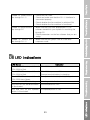
1
Table of contents
Introduction …………………………………………………………………………
3
Package Contents…………………………………………………………………
4
Installation Instructions……………………………………………………………
5
Antenna Installation…………………………………………………… 5
Installing Satellite Antenna…………………………………………… 5
Installing GPS Antenna………………………………………………
6
External Accessories …………………………………………………
6
Getting Started……………………………………………………………………… 7
Connection Interface…………………………………………………… 7
Setting up FDU-2500…………………………………………………
8
Using FDU-2500 as a desktop unit………………………………… 8
Using FDU-2500 as a wall mounted unit…………………………… 8
Mounting FDU-2500 on the wall……………………………………
8
Connecting Satellite Antenna………………………………………
8
Connecting GPS Antenna……………………………………………
9
Connecting FDU-2500 to Power Supply Adapter………………
9
Connecting Extension Phone to FDU-2500………………………
9
Connecting Group 3 Fax Machine to FDU-2500………………… 10
Connecting a PC to FDU-2500 through USB port……………
10
Docking Thuraya Terminal in FDU-2500 ………………………… 10
Undocking Thuraya Terminal from FDU-2500…………………… 11
Receiving / Making Calls……………………………………………………………12
Important…………………………………………………………………12
Receiving Calls …………………………………………………………12
Making Calls .……………………………………………………………13
Ending Calls …………………………………………………………… 13
Transferring Calls ………………………………………………………14
Volume Control …………………………………………………………14
Muting Microphone during Speakerphone Call ……………………15
Receiving / Sending Fax Message……………………………………………… 15
Receiving / Sending Fax through Fax machine …………………15
Receiving / Sending Fax through PC
1
……………………………16
Receiving / Sending Data Calls …………………………………………………17
Receiving Data Calls …………………………………………………17
Sending Data from PC ………………………………………………17
Charging the Thuraya Terminal Battery …………………………………………17
Code Locking Function ……………………………………………………………18
How to set up the Code locking function…………………………18
How to make a call
…………………………………………………19
In the case of Forgetting the PIN Code……………………………20
Supplementary Services
Troubleshooting
…………………………………………………………20
……………………………………………………………………21
Warnings! ………………………………………………………………21
Care and maintenance……………………………………………… 21
Common Problems
LED Indications
…………………………………………………22
……………………………………………………………………23
Warranty… ……………………………………………………………………………24
2
Introduction
Introduction
service provider) FDU-2500 and its accessories are designed and manufactured to
meet Thuraya’s superior specifications and world-class quality standards. FDU-2500
enhances the capabilities of the Thuraya terminal to meet your communication
requirements inside home and office.
The Thuraya terminal when used with FDU-2500, becomes a communication center
providing voice, fax and data communication. The built-in battery charger in FDU-2500
makes it possible for you to charge your Thuraya terminal while locked in the FDU.
Attention
Do not connect FDU-2500 with other products such as PSTN or general telephone
3
Fax Message
Receiving / Making Calls
Getting Started
line.
Installation Instructions
terminal. (Please note that Thuraya terminals are available separately from the local
Package Contents
FDU-2500 provides additional flexibility and convenience to your use of the Thuraya
Introduction
Package Contents
Installation Instructions
FDU-2500 Package consists of the following
FDU-2500 with Auxiliary handset
AC/DC Power adapter
Satellite antenna and mounting adapter
Satellite antenna cable (25meter)
Receiving / Making Calls
Getting Started
Package Contents
Fax Message
GPS antenna with cable (25meter)
USB driver CD, USB cable, RJ-11cable and
FDU-2500 User Manual
4
carefully. If you encounter any difficulty
in
intact and present, proceed with the
provider for assistance.
installation,
contact
your
service
installation. Please read the instructions
Antenna Installation
The FDU-2500 antennas set consists
connecting Satellite antenna to
of the following components:
1.
2.
FDU-2500 (25meter).
Satellite Antenna with mounting
3.
GPS Antenna with attached
adapter.
coaxial cable for connecting
Satellite antenna cable for
with FDU-2500 (25meter).
Installing Satellite Antenna
The satellite antenna is a rectangular
angle.
patch antenna, and is supplied along
adjusted
with a mounting adapter. The mounting
information provided on the
adapter also has an elevation angle
mounting adapter (Details will
adjust function.
be provided in the antenna
1.
Mount the antenna on to any
The
angle
using
can
the
be
angular
installation guide book).
suitable fixture (mounting pole
2.
or wall) on the rooftop using
Fix the antenna in such a way
that the connector at the base
the mounting brackets and the
is accessible when mounted.
bolts provided. The antenna
3.
Connect
the
should be facing skywards in
(marked
“Satellite
Antenna
the direction of the THURAYA
Cable”)
to
antenna
satellite and should be at the
connector located at the base
a
of the satellite antenna and
p
tighten it properly by turning it
p
clockwise.
r
length for a small loop and
o
secure the rest of the cable
p
coaxial
the
Leave
cable
enough
using the cable ties.
r
4.
Connect the other end of the
i
satellite antenna cable to the
a
satellite
t
marked “SAT” on the FDU-2500
e
by the side of the connectors.
5
antenna
Installation Instructions
that
Package Contents
ensuring
Installation Instructions
and
Getting Started
unpacking
FDU-2500 and all its accessories are
connector
Fax Message
After
Receiving / Making Calls
Installation Instructions
Introduction
5.
Adjust the azimuth and the elevation
angle of the antenna according to
where you are (Details will be provided
Installation Instructions
Package Contents
in the antenna installation guide book),
so as to ensure the highest signal quality,
indicated on the LCD display.
Installing GPS Antenna
The GPS antenna comes with attached
coaxial cable for connecting with the
FDU-2500 unit.
1.
Find an appropriate location
4.
Keep the antenna in place so
Getting Started
Make sure the antenna have a
that the drilled holes and the
clear view of the sky.Maintain a
separation of about 0.5 to 1 m
eter between GPS and Satellite
antenna.
screw holders are matched.
5.
Fix the antenna securely using
6.
Connect the free end of the
the screws provided.
attached cable to the GPS
2.
Receiving / Making Calls
Drill holes of adequate depth
on the surface.
antenna.
Mark locations of the“screw
antenna
holders”
“GPS” on the FDU-2500.
on the surface/roof
top for fixing the
connector
marked
antenna.
External Accessories
FDU-2500 needs to have external
accessories for full functionality. Please
make sure that you have the following:
1.
2.
3.
Group 3 Fax machine for
4.
FAX software for PC Fax.
5.
Extension phone.
Thuraya terminal with active
sending/ receiving Fax.
SIM card.
Fax Message
3.
on the rooftop to mount the
Personal Computer (PC) for
Data transfer and PC Fax.
Note: The RJ-11 cable should be 2-wire
inner at both ends.
6
Introduction
FDU-2500 is intended to be used as a desktop or wall-mounted phone while the
Thuraya terminal is docked. Slots are provided at the base of the unit to allow FDU-2500
to be hooked securely to a wall. Interfaces for connecting external equipments such as
Group 3 fax machine and PC are provided at the back side of the unit.
7
Fax Message
Receiving / Making Calls
Getting Started
Installation Instructions
Connection Interface
Package Contents
Getting Started
Package Contents
Using FDU-2500 as a
desktop unit
To use FDU-2500 as a desktop unit, find
Installation Instructions
Introduction
Setting up FDU-2500
FDU-2500 can be fixed on the wall by
an appropriate location on your desktop
where you can easily access the unit.
Make sure that you have an electrical
outlet nearby for powering up FDU-2500.
Using FDU-2500 as a wall
mounted unit
using the bracket. Slots for brackets are
basically provided. Slots for brackets are
provided on the FDU
Mounting FDU-2500 on the wall
Getting Started
1.
Find an appropriate location
5.
on the wall for placing the
Hook FDU-2500 to the bracket
on the wall.
FDU-2500 as a mounted unit.
2.
Place the bracket on the
fixing
location and mark the
location of screw hole.
3.
Place a suitable nails length on
the wall for mounting
Receiving / Making Calls
FDU-2500.
4.
Handset holder. Change the
direction of Handset holder
to a wall mounted unit.
Connecting Satellite Antenna
1.
Connect the coupler at the
2.
free end of the coaxial
turning it clockwise.
satellite antenna cable with
the connector marked “SAT”
Fax Message
Tighten the connector by
on FDU-2500.
8
Data Calls
Connecting GPS Antenna
Connect the coupler at the free
of
the
coaxial
FDU-2500.
GPS
2.
Tighten the connector by
turning it clockwise.
antenna cable to the connector
marked “GPS” on the
Connecting FDU-2500 to Power Supply Adapter
Plug
the
Power
Supply
Adapter
connector into the DC IN connector on
The power LED on the
FDU-2500.
FDU-2500 glows red
indicating that the unit is
Use the other end of the Power Supply
powered and ready for use.
Adapter to connect FDU-2500 to the
main power source.
1.
Connect the dc plug of
AC/DC
power
adapter
to
FDU-2500, and AC power
Terminal Battery
end
Code Locking Function
1.
Switch ON the power source.
external power source.
Connecting Extension Phone to FDU-2500
Extension phone can be connected to
marked “EXT” on FDU-2500.
FDU-2500 at RJ-11 interface using an
2.
RJ-11 cable. FDU-2500 includes two
Connect the other end of the
RJ-11 cable to the RJ-11
RJ-11 interfaces. Extension phone should
interface of the phone.
be connected to the RJ-11 interface
Note: You must have a phone unit and
marked “EXT”.
2-wire RJ-11 cable to use this feature.
1.
Plug one end of the RJ-11
Phone is not supplied with the
cable to the RJ-11 interface
FDU-2500 unit.
9
Troubleshooting
3.
LED Indications
Connect AC power to the
Supplementary
cord to AC/DC adapter.
2.
Introduction
Package Contents
Connecting Group 3 Fax Machine to FDU-2500
FDU-2500 can be used for sending and
Installation Instructions
marked “FAX” on FDU-2500.
to a Group 3 fax machine at the RJ-11
2.
Connect the other end of the
interface. FDU-2500 includes two RJ-11
RJ-11 cable to the Group 3
interfaces. Group 3 fax machine should
fax machine.
be connected to the RJ-11 interface
Note: Contact your service provider to
marked “FAX”.
check for Fax service on the SIM Card.
1.
Plug one end of the RJ-11
Connecting a PC to FDU-2500 through USB port
You
can
use
connecting
a
your
PC
FDU-2500
through
the
for
interface of FDU-2500.
USB
interface on FDU-2500.
1.
2.
Getting Started
cable to the RJ-11 interface
receiving fax messages when connected
To use USB interface, install the USB
Plug in one end of the USB
driver for FDU-2500 in the PC. USB
cable to the USB port of your
driver is included in a CD which is
PC.
provided with the product.
Connect the other end of the
Note: Contact your service provider to
USB cable to the USB
check for Data service on the SIM Card.
Docking Thuraya Terminal in FDU-2500
For successful operation of FDU-2500,
Thuraya terminal must be in ‘SAT Only’
Receiving / Making Calls
mode and data link rate is set to 19200
Baud.
Note: Ensure that the Dust cap behind the
Thuraya
terminal
is
removed
before
attempting to dock.
1.
Place Thuraya terminal with the
display facing up.
2.
Gently lower the Thuraya terminal
Fax Message
into the docking cradle provided
on
FDU-2500,
coupling
the
antenna hole with the antenna
connector. Switch on FDU-2500.
10
Data Calls
3.
Thuraya terminal display will
the
docking is done successfully
(There should be maximum
signal
strength in the display,
otherwise inform the service
p r o v i d e r ) .Ensure full signal
strength on the display.
Undocking Thuraya Terminal from FDU-2500
In FDU-2500, Locker device is installed
for mechanical locking. Thuraya terminal
Code Locking Function
couple of seconds i f
Terminal Battery
s h o w “ F i x e d A d a p t e r ” for
can’t be undocked until the locker is
Supplementary
unlocked.
First, find the status of FDU-2500 Locker
device, If the Locker is locked, unlock it
and do the next steps:
1.
Allow the Thuraya terminal to
complete
all
the
ongoing
Switch off the power of
3.
Press the Eject button.
FDU-2500.
Releasing Thuraya terminal
11
LED Indications
2.
Troubleshooting
functions.
Introduction
Receiving / Making Calls
conditions
are
met
before
7.
Making/
strength that is shown in the
Thuraya terminal display.
1.
FDU-2500 is switched ON.
2.
Thuraya terminal is switched
Important
ON.
When FDU-2500 is switched on it would
3.
SIM card is valid.
take upto ten seconds to reach the
4.
The connections are done
properly
5.
6.
as
given
in
normal working condition. FDU-2500 is
this
functional only when Thuraya terminal is
manual.
docked.
Thuraya terminal is in “SAT
terminal
only” mode and data link rate
FDU-2500.
is set to 19200 Baud.
FDU works only in the Thuraya satellite
Turaya terminal is docked in
FDU-2500
and
For
all
should
operations
be
Thuraya
docked
into
mode. Therefore, the setting in the menu
shows
of
the
Thuraya
terminal’s
system
“Fixed Adapter” for few of
preference must be set to “SAT only”
seconds and then show the
(for details, refer to Thuraya terminal
GPS location (It may not
user manual).
show
if
GPS
location
is
Receiving Calls
The incoming calls to FDU-2500 is
the call was not attended.
indicated by,
> Accepting Calls from the Auxiliary
1.
Ringing tone in the
Handset
speakerphone and extension
1.
Pick up the Auxiliary handset.
phone.
2.
Flashing of the Speakerphone
> Accepting Calls from the
LED on the top of
Speakerphone
FDU-2500.
1.
You can accept incoming calls at the
Speakerphone,
Auxiliary
handset,
Press the Speakerphone butt
on.
or
Extension phone.
Fax Message
Adequate satellite signal
Receiving a call.
Getting Started
Receiving / Making Calls
displayed).
FDU-2500. Make sure that all these
Installation Instructions
Package Contents
You can receive and make calls using
> Accepting Calls from Extension
Phone
Note
1.
The Speakerphone LED will remain ON if
Pick up the handset of the
Extension phone.
12
Data Calls
Making Calls
Method 2 :
outgoing calls. Make sure that FDU-2500
1.
Dial the destination number
is activated before proceeding with the
using Thuraya terminal keypad
call.
while the Auxiliary handset is
on the cradle.
> Calling from the Speakerphone
2. Pick up the Auxiliary handset.
Calls from Speakerphone can be made
by.
> Calling from the Extension
1. Dial the destination number
1.
Pick up the handset of the
keypad.
2.
Wait for the dial tone.
Press Call button on Thuraya
3.
Dial the destination number
using Thuraya terminal
the
Extension
phone
keypad.
> Calling from the Auxiliary Handset
4.
Press # on the Extension
Calls from Auxiliary handset can be
phone keypad as the last
made by any of the following method.
digit.
Method 1 :
1.
Pick up the Auxiliary handset.
Note:
2.
Wait for the dial tone.
Extension phone, you must dial # as the
3.
Dial the destination number
last digit after the destination number. In
using the Thuraya terminal
this case, Thuraya terminal will call 5
keypad.
seconds later, and in the case of dialing
Press call button on Thuraya
*as a last digit, Thuraya terminal will call
terminal.
instantly.
4.
To
make
the
call
from
the
Ending Calls
> Ending a Speakerphone Call
1.
handset
Press the Speakerphone butt
> Ending a Private Call
on.
1.
> Ending Calls From Extension Phone
1.
Place the Auxiliary handset on
FDU-2500.
Place the Extension phone
13
Supplementary
on
Troubleshooting
Terminal.
Code Locking Function
Extension phone.
LED Indications
2.
Terminal Battery
You can use the FDU-2500 for making
Introduction
Transferring Calls
Package Contents
Calls can be transferred between the Speakerphone, Auxiliary handset, and
Extension phone once the call has been established.
> Speakerphone to Auxiliary
Auxiliary handset on the cradle.
(conference call to privacy mode)
1.
> Speakerphone to Extension
Pick up the Auxiliary handset.
1.
handset.
auxiliary handset.
> Extension phone to Speakerphone
> Auxiliary handset to Speakerphone
Installation Instructions
Pick up the Extension phone
The call will be routed to the
1.
Press the Speakerphone
2.
Ensure speaker phone LED
(privacy mode to conference call)
buttonon FDU-2500.
1.
Press the Speakerphone
button on FDU-2500.
blinking
2.
Ensure speaker phone LED
extension phone on the cradle.
blinking
then
place
then
place
the
the
Receiving / Making Calls
Getting Started
Volume Control
You can control the volume of the
> Adjusting ringer tone volume
Speakerphone, auxiliary handset, and
1.
ringer tone using the Volume Up and
2.
Press the Volume Up/Volume
Volume Down buttons on FDU-2500.
Down button repeatedly to
> Adjusting auxiliary handset volume
increase /decrease the ringer
1.
Pick up the Auxiliary handset.
tone volume as required. You
2.
Press the Volume Up/Volume
can listen to the tone as you
Down button repeatedly to
do this and can adjust the
increase /decrease the
volume as required.
auxiliary handset volume as
required.
> Adjusting speakerphone volume
1.
Switch ON the speakerphone.
2.
Press the Volume Up/Volume
Down button repeatedly to
increase /decrease the
Fax Message
Switch ON FDU-2500.
speakerphone volume as
required.
14
Data Calls
1.
button. You will be able to hear the caller
Press the Mute button on
FDU-2500 once.
at the other end, but he/she will not be
able to hear you.
Note
If you pick up the Auxiliary handset now,
Note
the call automatically will be unmuted
Whenever a call is muted, the red mute
and routed to auxiliary handset.
LED on FDU-2500 will glow steadily.
> To unmute the call.
> Muting a speakerphone call
1.
Press the Mute button again.
Receiving / Sending Fax Message
You can use FDU-2500 for receiving and
through a PC connected at the USB or
sending fax messages. This can be done
DTE interface of FDU-2500. For sending
either
fax through PC, your PC should have
by
a
group
3
fax
machine
connected to the RJ-11 interface or
appropriate PC Fax Software installed.
Receiving / Sending Fax through Fax machine
Code Locking Function
To mute a Speakerphone call.
Speakerphone call by pressing the Mute
Supplementary
You can mute the microphone during a
Terminal Battery
Muting Microphone during Speakerphone Call
> Receiving Fax
Thuraya
terminal
in
FDU-2500.
FDU-2500.
2.
Switch on the group 3 fax
2.
Switch ON FDU-2500.
machine connected at the
3.
Switch on group 3 fax machine
RJ-11 interface of FDU-2500
that is connected to the RJ-11
and place the fax sheet on the
interface marked “FAX” on the
fax machine.
FDU-2500.
Note : A ring tone in the fax
3.
Switch ON FDU-2500.
4.
Dial the destination number
machine indicates an incoming fax
followed by “#”.
call.
5.
Dial
the
Data
connection
speed number with a call type
> Sending Fax
1.
Troubleshooting
Dock
number followed by “#”.
Dock the Thuraya terminal in
6.
15
Press Fax start button.
LED Indications
1.
Introduction
E.g. 12345678#32# then
First digit 1, 2, or 3 will indicate the fax
FAX Start button.
connection speed.
The fax will be sent now.
“1” indicates 2.4 Kbps speed.
Installation Instructions
Package Contents
“2” indicates 4.8 Kbps speed.
“3” indicates 9.6 Kbps speed.
You must press the fax start button after
Second digit 1 or 2 will indicate the call
entering the second “#”.
type.
“1” indicates data call.
“2” indicates fax call.
> Important
The two digits dialed between the two
#s indicate the following.
Receiving / Sending Fax through PC
interface of FDU, incoming fax
You can send/receive fax through a PC
calls will be received by the PC
connected to the USB or DTE interface
connected at the USB or DTE
of FDU-2500.
interface.
Getting Started
> Important!
> Sending Fax
For sending/receiving fax through PC,
1.
Dock Thuraya terminal in
installed in your PC.
2.
Connect the PC to the USB or
Note
3.
Switch ON FDU-2500.
While sending fax through PC connected
4.
Invoke the PC fax software.
at the USB or DTE interface, the fax
5.
While
you must have appropriate fax software
FDU-2500.
DTE interface of FDU-2500.
Fax Message
Receiving / Making Calls
software should be configured in the
class 2.0 mode.
> Receiving Fax
Dock
Thuraya
terminal
Enter the destination number.
in
7.
Select the document/file to be
Connect the PC to the USB or
8.
Use the appropriate option in
sent.
DTE interface of FDU-2500.
3.
fax
E.g.12345678
FDU-2500.
2.
the
resolution.
6.
1.
configuring
software, select ‘fine’ as a
the fax software to send the fax.
Switch ON FDU-2500.
Note: No need to dial #32# after the
4.
Activate the fax software.
destination number while using fax
5.
If there is no group 3 fax
on the PC
machine present at the RJ-11
16
Data Calls
The baud rate of PC data communication
connected at the USB or DTE interface.
software should be set up the 19200bps
To receive/make data calls by a PC,
(Baud rate of PC data communication
appropriate
software should be set to 19200bps both
communication
software should be installed in the PC.
in sender and recipient’s PC).
Receiving Data Calls
The PC connected through USB or DTE
4.
Invoke the data communication
5.
You will hear a special signal
interface to FDU-2500. To receive a
software.
data call on the PC appropriate data
software
should
be
tone in Thuraya terminal when
running, e.g. Hyper terminal (default
a data call is coming through.
program available on Windows OS).
1.
2.
6.
The data will be received by
Dock Thuraya terminal in
the
FDU-2500.
(Look up the S/W guide book
Connect PC through USB or
for the specific explanation).
communication
software
DTE interface.
3.
Switch ON FDU-2500.
Sending Data from PC
1. D o c k T h u r a y a t e r m i n a l i n
E.g. ATDT 12345678
FDU-2500.
5. Select the data file to be sent.
2. Switch ON FDU-2500.
6.
3. Invoke the data communication
Use appropriate options in the
data communication software to
software in your PC.
send the file now
4. Dial the destination number as
shown below.
(Look up the S/W guide book
for the specific explanation).
Charging Thuraya Terminal Battery
FDU-2500 comes with a built in battery
FDU will start charging the battery. The
charger for charging the Thuraya terminal.
charging status will be indicated by the
When the Thuraya terminal is docked and
red LED on top of
the Power Supply is switched ON, the
Thuraya terminal is fully charged ,the
17
FDU-2500. Once the
Troubleshooting
communication
LED Indications
data
Terminal Battery
Note
data calls. You can do this through a PC
Code Locking Function
Use FDU-2500 for receiving and making
Supplementary
Receiving / Sending Data Calls
Introduction
Package Contents
Installation Instructions
BATT LED will turn to green.
Code Locking Function
Extension
code
function is not for Thuraya terminal
locking function which is supported by
phone
is
used
for
connection but for FDU-2500 which has
FDU-2500. This code locking function is
the code locking function.
operated by entering passwords. This
How to set up the Code Locking Function
is successfully enabled.
The PIN Code of FDU-2500 is set to
> Disable PIN Code Locking Function
“0000” as a default.
1.
to RJ-11 interface marked
> How to enter the PIN Code
1.
“EXT” on the FDU-2500.
Connect the extension phone to
Pick up the extension phone
Getting Started
RJ-11 interface marked “EXT”
on the FDU-2500. Pick up the
Receiving / Making Calls
handset.
2.
Press “*#” → User Code →
3.
Hang up the phone after
extension phone handset.
2.
3.
“*” (ex. *#1234*)
Press “#*” → 0000 → * →
New Code (4 digit) → “*”,
earing
(ex. #*0000*1234*)
indicates that the PIN Code
Hang up the phone after
hearing
Fax Message
Connect the extension phone
the
beep
the
beep
which
is successfully disabled.
which
indicates that the PIN Code
> How to Change the PIN Code
is successfully changed.
1.
Connect the extension phone
to RJ-11 interface marked
> Enable PIN Code Locking Function
1.
“EXT” on the FDU-2500.
Connect the extension phone
to
RJ-11
interface
Pick up the extension phone
marked
handset.
“EXT” on the FDU-2500. Pick
up
the
extension
2.
phone
Press “#*” → Old Code
→ * → New Code (4 digit)
handset.
→ “*” (ex. #*1234*5678*)
2.
Press “**” → User Code →
3.
Hang up the phone after
indicates that the PIN Code
hearing
is successfully changed.
3.
“*” (ex. **1234*)
the
beep
Hang up the phone after
hearing
which
indicates that the PIN Code
18
the
beep
which
Data Calls
Voice Call
EXT interface
Telephone Number → #
FAX Call
FAX interface
FAX Number → # → 32 → # → Start Button
PC FAX S/W : FAX Number
Data Call
USB interface
Running PC S/W
Data Call Number
DTE interface
Running PC S/W
Data Call Number
FAX interface
Running PC S/W
Data Call Number → # → 31 → #
Terminal Battery
Calling Methods with PIN Code disabled
Code Locking Function
How to make a call
PIN Code → * → Telephone Number → #
FAX Call
FAX interface
PIN Code → * → FAX Number → # → 32 → # →
Start Button
PC FAX S/W : FAX Number
Data Call
USB interface
Running PC S/W
Data Call Number
DTE interface
Running PC S/W
Data Call Number
FAX interface
Running PC S/W
PIN Code → * → Data Call Number → # → 31 → #
19
Troubleshooting
EXT interface
LED Indications
Voice Call
Supplementary
Calling Methods with PIN Code enabled
Introduction
Package Contents
In the case of Forgetting the PIN Code
If you forget the PIN Code that you set
should remember the PIN Code you set
up, you should reset your FDU-2500 by
up, and write it down in a safe place.
visiting the service center. So, you
Supplementary Services
There are a
services
host of supplementary
supported
by
the
Set
Thuraya
FDU-2500.
Receiving / Making Calls
Getting Started
Installation Instructions
terminal, which are also supported by
Fax Message
these
terminal.
20
functions
using
Thuraya
Data Calls
Troubleshooting
are
> General
troubleshooting. In case you face any
Do not place the FDU-2500 in
problems, contact the nearest service
a wet area.
center. Only authorized service person
Do not expose FDU-2500 to
can repair the equipment.
temperatures greater than +55°
Celsius or less than 0° Celsius.
> Antenna
Do not expose FDU-2500 to
Use only the antenna and cable that has
moisture, dust etc.
been
your
Avoid placing FDU-2500 close
FDU-2500. Unauthorized antenna, cable,
to open flames or any source
and
of heat.
specifically
cable
designed
length
for
modifications,
or
attachments could damage FDU-2500
Do not expose FDU-2500 to
and may violate the relevant regulations,
direct sunlight.
causing loss of performance and radio
Do not disassemble FDU-2500;
frequency
this will void your warranty.
(RF)
energy
above
the
recommended limits. If your FDU-2500’s
antenna gets damaged, please take it to
Care and maintenance
FDU-2500 is a product of superior
temperatures can shorten the life of
design and craftsmanship and should be
electronic devices, damage batteries,
treated
and warp or melt certain plastics.
with
care.
The
following
suggestions will help you to fulfill any
warranty obligations and allow you to
Do not attempt to open it. Mishandling of
enjoy this product for many years.
the device may damage it.
Do not use or store FDU-2500 in dusty,
dirty areas.
Code Locking Function
You
Supplementary
components.
advised not to carry out any kind of
Do not drop, apply pressure or shake it.
Rough handling can break internal circuit
Do not store it in hot areas. High
boards.
21
LED Indications
serviceable
Troubleshooting
an authorized service provider.
FDU-2500 does not contain consumer
Terminal Battery
Warnings!
> Servicing
Introduction
Package Contents
could
or strong detergents to clean it. Wipe it
violate
smoothly with a soft cloth.
devices.
Receiving / Making Calls
regulations
and
regarding
may
radio
If the phone, battery, charger, or any
device’s
accessory does not function properly,
moving
parts
and
prevent
proper operation.
take it to your nearest Authorized Service
Center. The personnel there will assist
Use only the supplied or an approved
you,
replacement
service.
antenna.
Unauthorized
and
if
necessary,
arrange
for
antennas, modifications or attachments
Common Problems
Thuraya terminal is undocked
FDU-2500 should be switched
properly.
ON.
Thuraya terminal not in “SAT
Adapter” message on Thuraya
Only” mode.
terminal for few seconds and
Thuraya terminal is switched
power/charging
OFF.
FDU-2500)
There is no enough satellite
Connections are not proper
signal strength (indicated in
and firm.
Thuraya
terminal
(indicated
by
“Fixed
LED
display.
There should be minimum two
bars
present.
Otherwise,
adjust the antenna properly).
The SIM card is invalid.
Problem
Unable
Solution
to
make/receive
calls
- Check the PIN Code.
- Dial through Thuraya terminal if OK, then check
the RJ-11 connection.
- If Extension Phone is not working, try with
Auxiliary Handset of FDU-2500 and confirm it’s
working. If you can make a call with the auxiliary
handset of FDU-2500, then check Extension
phone, else call the service provider.
The auxiliary handset not
Fax Message
damage the phone
Do not paint it. Paint can clog the
Getting Started
Installation Instructions
Do not use chemicals, cleaning solvents,
working
Speakerphone not working
- Check whether the auxiliary handset is
connected properly.
- Make sure that the speakerphone is ON.
- Select appropriate volume level.
22
on
Data Calls
- Check the PIN Code.
fax through RJ-11
- Check and make sure that the RJ-11 interface is
connected properly.
- Check whether the fax machine is switched ON.
- Check whether the fax machine is functional.
Unable to Send/Receive
fax through PC
- Make sure that you have appropriate PC Fax
software installed in your system for receiving fax
through PC.
- Check parameters on the fax software that you are
Terminal Battery
Unable to send/receive
fax through RJ-11
response mode.
LED Indications
LED Status
The Power LED on top middle of
Indication
FDU-2500 is powered ON.
FDU-2500 is Red.
The BATT LED on top middle of
FDU-2500 is powered ON.
FDU-2500 is Red.
Thuraya terminal battery is charging.
The BATT LED on top middle of
Thuraya terminal battery is fully charged.
Supplementary
- Make sure that the group 3 fax is in the auto
Code Locking Function
using.
Unable to receive the
Incoming call indication.
The Red LED on the Mute button
The microphone is OFF.
is illuminated.
The Red LED on the Speaker
The speakerphone is ON.
button is illuminated.
23
LED Indications
Speakerphone LED is flashing
Troubleshooting
FDU-2500 turns Green.
Warranty
Limited Warranty
FDU-2500
This Limited Warranty is provided to the original purchaser of FDU-2500. This Limited
Warranty is non-transferable in nature.
Warranty Coverage and Service
APSI warrants all new FDU-2500 terminals to be free from defects in material and
workmanship under normal use and wear, for a period of one year (1 year) from the
date of purchase. If under normal use the product becomes defective in materials or
workmanship and is returned to an APSI Authorized Service Center during the warranty
period, the product will be repaired or replaced at no charge to the purchaser. The
purchaser shall be required to provide reasonable proof of the date of purchase of the
Product.
Repair or replacement of the Product is subject to APSI System Design’s sole and
exclusive option. Reconditioned replacement components, parts, units, or materials
may be used if the Product is repaired or replaced. Cost incurred in the removal,
de-installation or reinstallation of the Product are not covered.
This Limited Warranty will be void in its entirety if the Product is serviced by anyone
other than APSI or an APSI Authorized Service Center. The User’s sole and exclusive
remedy shall be repair or replacement of the Product. APSI neither assumes nor
authorizes any Authorized Service Center or any other person or entity to assume any
other obligation or liability beyond that which has been specified in this Limited
Warranty.
Limitation of Liability
All liability and obligations of APSI under this Limited Warranty shall terminate on the
completion of the warranty period of one year, calculated from the date of purchase of
the Product by the original purchaser. The purchaser shall fill in the warranty card
attached in the User Manual and get it duly stamped and signed by the Dealer as proof
of purchase. This limited warranty sets forth the entire responsibility of APSI with
respect to the product. There are no other liabilities of APSI arising from the sale of the
Product whether based on warranty, contract, negligence or any other theories of
liability.
This Warranty does not cover the following
APSI will not be responsible for products or accessories not manufactured or provided
by APSI. APSI will not take responsibility for the failures caused by misuse, accident,
alteration or neglect, removal or repair, neglect or failure to follow instructions as to
installation and maintenance, fire, flood or other natural calamities. APSI will not
guarantee the performance of the Product when used in combination with other
products or equipment.
24