1
FG1 FLUXGATE COMPASS USER MANUAL
FG1 manual 01
November 2012
Software releases:
1.2.3 31oct2012
Hardware versions:
V3 26jun2012
1 of 12
Table of Contents
1 xIntroduction and description of fluxgate compass.
1.1
Description of compass
1.2
Connections
1.2.1
Normal
1.2.2
Variants -CP
1.3
Switches
1.4
Indicator light
1.5
Power supply.
1.6
Mounting
2 Connecting the compass to your application.
2.1
2.2
To a NMEA-0183 instrument.
To a PC serial port.
3 Output formats available from compass.
3.1
3.2
NMEA-0183
Furuno AD-10
4 Calibrating the compass.
4.1
4.2
4.3
4.4
4.5
Why the compass needs calibrating.
Starting calibration.
Aborting a bad calibration.
Setting reference NORTH heading
Set-up suggestions
5 Configuration
6 References
1. Introduction and description of fluxgate compass.
1.1 Description of compass.
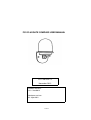
The FG1 NMEA compass unit is a complete component for a compass indicating system,
RADAR ‘North-up’ input or autopilot. It is housed in a water-resistant enclosure so it can be
mounted outside a steel hull. It delivers heading data in two industry-standard forms. .
The FG1 contains a fluxgate with floating core surrounded by high-precision interface circuits
which, together with the special clockwise/anticlockwise and offset nulling sequence allow a
microprocessor to acquire a binary value from two orthogonal sensors of the horizontal
component of the Earth’s magnetic field. The processor calculates the vector from these
values, uses a calibration table to correct for local field disturbance errors, offsets the result
and then presents the data in a manner which has been requested. Such requests alter the
2 of 12
frequency of the data, the degree of filtering and the offset value. Calibration sequences can
also be commanded.
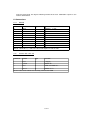
1.2 Connections
1.2.1
Normal
Conductor
Colour
Type
Function
1
Red
P
+Supply
2
3
Yellow
Brown
O
I
Furuno AD-10 Clock
NMEA IN-
4
White
I
NMEA IN+
5
6
7
8
9
Black
Green
Blue
Violet
Screen
P
O
P
O
P
GND
NMEA OUT+
GND
Furuno AD-10 Data
GND
8-30v
NOTE Conductors 5, 7 and 9 are connected together inside the FG1
1.2.2
Variants with suffix -CP
Conductor
Colour
Type
Function
1
Red
P
+ Supply
2
Yellow
I
NMEA IN +
3
Blue
P
GND and NMEA IN -
4
Green
O
NMEA OUT +
NOTE Cable foil and drain wire internally connected to GND
3 of 12
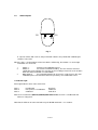
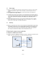
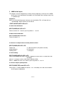
1.3
Switch Inputs
S2
S1
Fig 1
E cept for variants with suffix -S, two push-button switches are provided for calibrating the
compass in the field.
When the FG is 1 viewed from the front face with the LED facing, then Switch 1 is on the right
and Switch 2 is on the left.
1
2
3
Switch 1:
Start the auto-calibration process
Switch 2:
Set reference NORTH heading. The FG1 must be mounted
upright but at any azimuth. Pressing S2 sets the heading to zero and so can be done
when the whole installation is headed North.
Both together
Pressing both together for at least one second causes the autocalibration process to halt and restores the previously saved calibration values.
1.4 Indicator light
A blue light indicates three states of the FG1.
State 1
State 2
State 3
Uncalibrated
In the process of calibration
Calibrated
long flash
continuous
short flash
After the reset command, $PATC,IIHDG,0CV<CR><LF>, the FG1 is uncalibrated and
will have a long flash.
Note that the LED can be turned off and on by the DLED command – see section 5.
4 of 12
1.5
Power supply
The compass is compatible with any DC power supply of between 8 and 30 Vdc. Typical supply
current during operation is approx. 25mA. The compass is protected against reversed
polarity.
Note that the operation of the LED adds another 10mA and that during auto-calibration the
consumption can be as high as 60mA.
Care should be taken to make sure the compass is not situated too close to the power supply, as
it’s accuracy may be affected by either the iron in the mains transformer, or by magnetic field
‘noise’ from a switching power supply. It is not possible to cover all possible scenarios here,
and it remains up to the user to determine the suitability of a possible location for the
compass.
Note that the output from the FG1 takes several seconds to stabilize after a power is applied;
the time taken depends on the damping settings. There is a command - see section 5 –
which can be used to suppress the output after power-up.
1.6
Mounting
The compass is fixed to the chassis of the vessel or vehicle in the upright position using the fixing
holes shown in the data sheet. It does not matter which way it faces as the azimuth can be
set to North at any time the chassis is orientated North. Alternatively if the azimuth of the
chassis is known, then the FG1 may be rotated before fixing to North using a protractor.
S2 is then pressed and then the compass can be mounted on the chassis.
2 Connecting the compass to your application
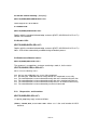
2.1 Compass to a NMEA-0183 instrument
The hardware on which the NMEA-0183 standard is based on is a balanced serial protocol called
RS422. This means that two wires are need for send and two for receive.
6
NMEA OUT +
5
GND
4
NMEA IN+
+
NMEA current
source
3
NMEA IN-
E ternal NMEA device
Fig 2
5 of 12
Note that the GND wire is used for the current return path. This might be shared with
the NMEA- wire in some installations.
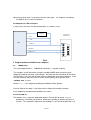
2.2 Compass to a PC serial port
In many cases the wires can be joined directly as shown in Fig 2.
.
1 +8-30V
+
PO W ER
SOU RCE
CO M PO R T D
CONNECTOR
7 GND
5 GND
FG1
5
3 NMEA IN -
3
4 NMEA IN +
6 NMEA OUT +
2
Fig 3
3 Output formats available from compass
3.1
NMEA-0183
The serial output format is: 4800 Baud, 8 data bits, 1 stop bit, no parity.
The compass sends information using the standard NMEA-0183 sentence ‘HDG’:
Magnetic Heading, Deviation, and Variation. But note that the information of Deviation
and Variation is not sent and so blank fields are defined by consecutive commas. In the
FG1 the sentence may have one of several forms typically of the general form:
$HCHDG,hhh.h etc
Where hhh.h is the magnetic heading from 000.0 to 359.9 degrees
Also the Rate-of-turn data is sent either with or without the heading sentence.
For a complete list of output formats available see Section 5
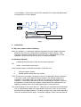
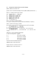
3.2 Furuno AD-10
The compass has a separate, dedicated output in Furuno AD-10 format. This is a
proprietary 4 character serial format, which gives heading in degrees and tens of
minutes. The string 0872 represents the heading 87° 20’ so that the precision is to
6 of 12
1/6 of a degree. At the same time the FG1 would be also sending the NMEA data
to a precision of 1/10 of a degree.
Clock
Data
480µs
Duration of data is x16 clocks each
high=low=30
µs. Total = 480µs.
100ms minimum
Frequency of data packets is set by
the interval command. Ma = 10Hz
Fig 4
4
Calibration
4.1 Why the compass needs calibrating
When any compass is installed the magnetic characteristics of the whole installation
affect the way the Earth’s field reaches the detector inside the device. Each
individual installation will be different and so the FG1 is equipped with an autocalibration routine which corrects for these installation distortions.
4.2 Starting calibration
-
A NMEA-0183 command can be sent to initiate the process.
-
Switch 1 can be pressed to start it.
OR
There are two compass calibration techniques in common use:
1
2
Constant angular velocity
Double rotation without constant velocity.
The FG1 uses the first method. The process consists of rotating the whole installation
in the Earth’s field so that both permanent magnets and induced magnets are
corrected. The method used is the single turn at a constant rate and this rate
should be in range 60 to 180 seconds for the full 400 degrees needed. The whole
arrangement is turned at constant angular velocity because the method relies on
applying a correction when the heading measured is uneven with time.
The second method is not used in the FG1. Technician has evaluated the method which
uses a mathematical model of an ideal compass and treats errors as arising from
distortion due to magnetic objects. The ideal error plot of the field vector would be a
circle with no offset from the origin. Permanent magnets (‘hard’) have the effect of
7 of 12
shifting the centre from the origin and induced magnets (‘soft’) modify the circle into
an ellipse. The results of our investigation show that there is always a residual
error due to the fact that real magnetic objects do not behave exactly according to
the model outlined. Technician is aware that the need for a constant angular velocity
is onerous but the benefit is that it provides a very low residual error – less than
0.5°.
Note that the calibration is different if the unit is mounted upside-down.
Calibration must always be done with the unit in its final mounted position. The essential
point of the calibration is remove the influence of external magnetic components in
the vicinity – the nearby pieces of iron and steel –so it is essential that these remain
unchanged after calibration. If any significant iron component is altered – such as
the installation of new equipment or replacement of equipment such as winches or
engines – then the calibration must be re-done.
4.3 Terminating a bad calibration
If the process is faulty in any way – such as would happen if the manoeuvre cannot be
completed, the process can be terminated by the NMEA command listed and the
original factory default (linear) table is restored. Alternatively this can be done by
pressing both Switches together for at least 1 second.
NOTE that there should be a delay of at least 5 seconds after termination before a new
calibration process is initiated.
4.4 Setting reference NORTH heading
Switch 2 (and also a NMEA command) is provided to set ‘zero’. The FG1 should
a.
first be auto-calibrated
b.
then be aligned to North
4.5 Set-up suggestions
When the FG1 is fixed in place and connected it can be calibrated as described
above. Choose a calm day and a region of water where there are no currents. Set
the boat turning to left or right at a slow rate and fix the wheel or tiller. Then, when
the turning is steadily under way, press the auto-calibrate button and watch the
LED.
When calibration is completed the boat can be on its way and the next task is to set
North. This is best done by identifying transits on a chart and heading the boat on
the transit. Again this should be done in the same conditions so that the heading
can be lined up on the transit and maintained while the set-zero button is pressed.
8 of 12
5
NMEA-0183 inputs
The compass can be configured by sending various proprietary sentences to its NMEA0183 input. Once configured, the compass will remember those settings every time
it is powered up.
Response:
When any of the following input sentences are received the FG1 will reply with an
‘acknowledge’ output sentence of the format:
$PATC,HCHDG,ACK<CR><LF>
5.1Start Auto-Calibration
$PATC,IIHDG,IAC<CR><LF>
Refer to section 4.2. Same as pressing Switch 1 – see 4.4.
5.2Abort Auto-Calibration.
$PATC,IIHDG,XCL<CR><LF>
Refer to section 1.3.
5.3 Resets all compass data to factory default values:
$PATC,IIHDG,0CV<CR><LF>
Output rate
output damping
heading offset
u= 100 milliseconds (10 updates/second),
d= 50 percent
f= 0 degrees.
5.4 Set heading:
$PATC,IIHDG,AHD,fff.f<CR><LF>
Forces the heading to a certain value by supplying an offset which is stored and used
thereafter.
Where f is in degrees with a valid range of 000.0 to 359.9
When f = 000.0 the result is the same as pressing switch 2 – see 1.3.
5.5 Set the Output update period:
$PATC,IIHDG,TXP,uuuu<CR><LF>
Valid range is u=100 to 3000 milliseconds. This is limited by max. data rate of NMEA0183 output at 4800 baud.
9 of 12
5.6 Set the internal filtering: ('damping')
$PATC,IIHDG,DHD,ddd.d<CR><LF>
Valid range for d is 0 to 100.0%
5.7 Enable LED:
$PATC,IIHDG,ELED<CR><LF>
Replies with the standard acknowledge sentence ($PATC,HCHDG,ACK<CR><LF>).
Default: LED enabled.
5.8 Disable LED:
$PATC,IIHDG,DLED<CR><LF>
Replies with the standard acknowledge sentence ($PATC,HCHDG,ACK<CR><LF>).
Note : LED will be automatically enabled during calibration process.
5.9 Read auto-calibration status:
$PATC,IIHDG,CEC<CR><LF>
The response is a proprietary sentence containing a code, k, for the status:
$PATC,HCHDG,CEC,k<CR><LF>
Where k has the following values:
k=0
k=1
k=2
k=3
k=4
k=5
5.10
the last auto-calibration was successfully completed.
Resetting the calibration data to factory default was completed successfully.
The autocalibration has been aborted internally due to the rotation being too slow.
The autocalibration has been aborted internally due to the rotation being too fast.
The autocalibration has been aborted internally because of rotation inconsistency.
The autocalibration has been aborted by an external command.
Request the serial number:
$PATC,IIHDG,RID<CR><LF>
A special proprietary reply sentence follows:
$PATC,IIHDG,RID,ssss<CR><LF> where ssss is the serial number in ASCII
decimal.
10 of 12
5.11
Configure the output sentence structure and type:
$PATC,IIHDG,CFG,abc<CR><LF>
[Replies with the standard acknowledge sentence $PATC,HCHDG,ACK<CR><LF>. ]
Where 'a' is heading sentence type as follows:
a=0 : $HCHDG,hhh.h,,,,<CR><LF>
a=1 : $HCHDT,hhh.h,T<CR><LF>
a=2 : $HCHDM,hhh.h,M<CR><LF>
a=3 : $HCHCC,hhh.h<CR><LF>
a=4 : $HEHDT,hhh.h<CR><LF>
a=5: no heading data sent
hhh.h is the compass heading in degrees
(this compass heading field will be omitted when auto-calibration is in process)
and 'b' is sentence end structure as follows:
b=0 : direction sentence will NOT include checksum nor unit ID serial number.
e.g. $HCHDG,hhh.h,,,,<CR><LF>
b=1 : direction sentence will include a checksum.
e.g. $HCHDG,hhh.h,,,,*cc<CR><LF> (cc is the checksum)
b=2 : include the serial number.
e.g. $HCHDG,hhh.h,,,,*ssss<CR><LF> (ssss is the unit’s serial
number)
and where 'c' has the following significance:
c = 0 or is missing means no ROT
c=1
ROT with 8s average
c=2
ROT with 16s average
c=3
ROT with 32s average
c=4
ROT with 64s average
The form of the transmitted sentence is:
$HFROT,zxxx.x,A*cc<CR><LF>
Except when a=4 when the form is
$HEROT,zxxx.x,A*cc<CR><LF>
11 of 12
and where z = sign as follows:
+ (or missing) turning to starboard (i.e. heading value is increasing)
-
turning to port (i.e. heading value is decreasing)
and cc = checksum
xxx.x = Rate of Turn in degrees per minute
6
References
1
2
FG1 data sheet
NMEA-0183 specification
12 of 12
![000 CASORT [9].book](http://vs1.manualzilla.com/store/data/005753997_1-6c1117a0f29b8b2731a0aa33cfc5a43b-150x150.png)