1
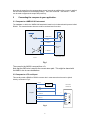
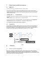
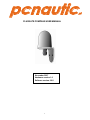
pcnautic
FLUXGATE COMPASS USER MANUAL
November 2007
Hardware version 1.0
Software version 0.0.8
1
.nl
Table of Contents
1 Introduction and description of fluxgate compass.
1.1
1.2
1.3
1.4
1.5
Description of compass
Connections
Switches
Indicator light
Power supply.
2 Connecting the compass to your application.
2.1
2.2
To a NMEA-0183 instrument.
To a PC serial port.
3 Output formats available from compass.
3.1
3.2
NMEA-0183
Furuno AD-10
4 Calibrating the compass.
4.1
4.2
4.3
4.4
Why the compass needs calibrating.
Starting calibration.
Aborting a bad calibration.
Setting reference NORTH heading.
5 Configuration
6 References
1. Introduction and description of fluxgate compass.
1.1 Description of compass.
The NMEA compass unit is a complete component for a compass indicating system,
RADAR ‘North-up’ input or autopilot. It is housed in a water-resistant enclosure so it can be
mounted outside a steel hull. It delivers heading data in two industry-standard forms. .
The compass contains a fluxgate with floating core surrounded by high-precision interface circuits
which, together with the special clockwise/anticlockwise and offset nulling sequence allow a
microprocessor to acquire a binary value from two orthogonal sensors of the horizontal
component of the Earth’s magnetic field. The processor calculates the vector from these values,
uses a calibration table to correct for local field disturbance errors, offsets the result and then
presents the data in a manner which has been requested. Such requests alter the frequency of
the data, the degree of filtering and the offset value. Calibration sequences can also be
commanded.
2
The Compass is available with dip-angle tilt tolerance of either 35° or 45°:
TYPE-35
TYPE-45
Software releases:
0.0.5 Initial
0.0.6 HDT added
0.0.7 other output sentences added
1.2
Connections
Conductor.
Colour
Function
1
2
3
4
5
6
7
8
Orange
Orange/W
Brown
Brown/W
Green
Green/W
Blue
Blue/W
power
output
input
input
signal
output
power
output
1.2
+8-30v
Furuno Clock
NMEA INNMEA IN+
GND
NMEA OUT+
GND
Furuno Data
Switch Inputs
1
2
Switch input 1: Start / Exit auto-calibration.
Switch input 2: Set reference NORTH heading
Two pushbutton switches are provided to enable the user to calibrate the compass in the field.
Switch 1
Switch 2
1.3
starts the auto-calibration process
exits (cancels) the calibration process and restores the previously saved
calibration.
sets the reference North heading. Since it is not always possible to mount the
compass board such that it faces due north, the reference North input may be
used to force the compass to treat any orientation as 0 degrees.
Indicator light
A blue light indicates three states of the Compass.
State 1
State 2
State 3
Uncalibrated
In the process of calibration
Calibrated
long flash
continuous
short flash
Note that the LED can be turned off and on by the DLED command – see section 5.
1.4 Power supply.
The compass is compatible with any DC power supply of between 8 and 30 Vdc. Typical supply
current during operation is approx. 25mA. The compass is protected against reversed polarity.
Care should be taken to make sure the compass is not situated too close to the power supply, as
it’s accuracy may be affected by either the iron in the mains transformer, or by magnetic field
‘noise’ from a switching power supply. It is not possible to cover all possible scenarios here, and it
remains up to the user to determine the suitability of a possible location for the compass.
3
Note that the output from the compass takes several seconds to stabilize after a power is applied;
the time taken depends on the damping settings. There is a command - see section 5 – which
can be used to suppress the output after power-up.
2
Connecting the compass to your application.
2.1 Compass to a NMEA-0183 instrument.
The hardware on which the NMEA-0183 standard is based on is a balanced serial protocol called
RS422. This means that two wires are need for send and two for receive.
6 NMEA OUT +
5
GND
4 NMEA IN+
+
NMEA current
source
3 NMEA IN-
External NMEA device
compass
Fig 1
The current in the A4020 is sourced from +5v.
Note that the GND wire is used for the current return path. This might be shared with
the NMEA- wire in some installations.
2.2 Compass to a PC serial port.
This usually needs a RS422 to RS232 converter but in most cases the wires can be joined
directly as shown in Fig 2.
+
1 +8-30V
POWER
SOURCE
COM PORT D
CONNECTOR
7 GND
5 GND
compass
5
3 NMEA IN -
3
4 NMEA IN +
6 NMEA OUT +
2
Fig 2
4
3
Output formats available from compass.
3.1
NMEA-0183
The serial output format is: 4800 Baud, 8 data bits, 1 stop bit, no parity.
The compass sends information using the standard NMEA-0183 sentence ‘HDG’: Magnetic Heading,
Deviation, and Variation. But note that the information of Deviation and Variation is not sent and so blank
fields are defined by consecutive commas. In the compass the sentence may have one of several forms
typically of the general form:
$HCHDG,hhh.h,,,,*ssss<CR><LF>
where hhh.h represents the magnetic heading with one decimal place of precision, i.e: 000.0 to 359.9
degrees.
And where ssss is either a 4 digit checksum or a 4 digit serial number.
The value returned as ss is a two digit checksum. The choice depends on the configuration
command described at the end of section 5. The default is 4 digit checksum.
For a complete list of output formats available see Section 5
3.2
Furuno AD-10
The compass has a separate, dedicated output in Furuno AD-10 format. This is a proprietary 4
character serial format, which gives heading in degrees and tens of minutes. The string 0872
represents the heading 87° 20’ so that the precision is to 1/6 of a degree. At the same time the
compass would be also sending the NMEA data to a precision of 1/10 of a degree.
4
4.1
Calibration
Fig 3
Why the compass needs calibrating.
When any compass is installed the magnetic characteristics of the whole installation
affect the way the Earth’s field reaches the detector inside the device. Each individual
installation will be different and so the compass is equipped with an auto-calibration routine
which corrects for these installation distortions.
5
4.2
Starting calibration.
-
A NMEA-0183 command can be sent to initiate the process.
-
Switch 1 can be pressed to start it.
The process consists of rotating the whole installation in the Earth’s field so that both
permanent magnets and induced magnets are corrected. The method used is the single
turn at a constant rate and this rate should be in range 60 to 180 seconds for the full 400
degrees needed. The whole arrangement is turned at constant angular velocity because
the method relies on applying a correction when the heading measured is uneven with
time.
There is another method, which is to treat errors as
arising from distortion due to magnetic objects. This is the classical compass swinging
approach. The ideal error plot is a circle with no offset from the origin. Permanent
magnets (‘hard’) have the effect of shifting the centre from the origin and induced
magnets (‘soft’) modify the circle into an ellipse. Then results of our investigation show
that there is always a residual error due to magnetic objects behaving exactly according
to the model outlined. Autonnic are aware that the need for a constant angular velocity
is onerous but it provides very low residual error – less than 0.5°.
Note that the calibration is different if the unit is mounted upside-down and must be done
with the unit in its final mounted position. The essential point of the calibration is remove
the influence of external magnetic components in the vicinity – the nearby pieces of iron
and steel.
The output /CE is asserted low during this process and is provided so that the status can
be monitored. /CE can be used to operate an LED drawing a current of not more than
20mA from a +5v (maximum) supply.
4.3
Aborting a bad calibration.
If the process is faulty in any way – such as would happen if the manoeuvre cannot be
completed, the process can be terminated by the NMEA command listed and the original
factory default (linear) table is restored.
4.4
Setting reference NORTH heading.
A separate input switch (and corresponding NMEA command) is provided to set ‘zero’. The
whole installation, after auto-calibration, is aligned to North and this is taken as zero degrees
when the switch is pressed.
5
NMEA-0183 inputs
The compass can be configured by sending various proprietary sentences to its NMEA-0183
input. Once configured, the compass will remember those settings every time it is powered up.
6
Response:
When any of the following input sentences are received the A5020 will reply with an ‘acknowledge’ output
sentence of the format:
$PATC,HCHDG,ACK<CR><LF>
Start Auto-Calibration:
Refer to section 4.2. Same as pressing Switch 1.
$PATC,IIHDG,IAC<CR><LF>
Abort Auto-Calibration:
Refer to section 4.3.
$PATC,IIHDG,XCL<CR><LF>
Reset compass to factory default: Resets all compass data to factory default values:
$PATC,IIHDG,OCV<CR><LF> Output rate = 100 milliseconds (10 updates/second),
output damping = 50 percent, heading offset f= 0 degrees.
Set Reference ‘NORTH’ heading:
Where f is in degrees with a valid range of 000.0 to 359.9
$PATC,IIHDG,AHD,fff.f<CR><LF> When f = 000.0 the result is the same as
pressing switch 2 – see 4.4.
Set Output update period:
Valid range is 100 to 3000 milliseconds. This is limited
by max. data rate of NMEA-0183 output at 4800
$PATC,IIHDG,TXP,x.x<CR><LF>
baud.
$PATC,IIHDG,ELED<CR><LF>
Enable LED (or set LED on)
reply with the standard acknowledge sentence ($PATC,HCHDG,ACK<CR><LF>).
Default: LED enabled.
$PATC,IIHDG,DLED<CR><LF>
Disable LED (or set LED off)
reply with the standard acknowledge sentence ($PATC,HCHDG,ACK<CR><LF>).
Note : LED will be automatically enabled during calibration process.
$PATC,IIHDG,DLY,x.x<CR><LF>
Set the period after power up during which the heading field in the NMEA sentence will be omitted.
Where x.x is the period value in seconds, 0 to 9.9 (entering larger periods will result in truncated values)
[i.e. if enter 12.4, 2.4 will be accepted as the period value].
Note : same applied after calibration process.
Default: period = 0 second.
$PATC,IIHDG,CFG,ab<CR><LF>
add a=4 : $HEHDT,hhh.h<CR><LF>
Request Status: Read out the last auto-calibration status.
$PATC,IIHDG,CEC<CR><LF>
The response is a proprietary sentence containing a code, k, for the status:
$PATC,IIHDG,CEC,k<CR><LF>
k=0
k=1
k=2
k=3
the last auto-calibration was successfully completed.
Resetting the calibration data to factory default was completed successfully.
The autocalibration has been aborted internally due to the rotation being too slow.
The autocalibration has been aborted internally due to the rotation being too fast.
7
k=4 The autocalibration has been aborted internally because of rotation inconsistency.
k=5 The autocalibration has been aborted by an external command.
Report unit’s serial number:
$PATC,IIHDG,RID<CR><LF>
A special proprietary reply sentence follows:
$PATC,WIHDG,RID,ssss<CR><LF> where ssss is the serial number in ASCII decimal.
Configure the output sentence structure and type:
$PATC,IIHDG,CFG,ab<CR><LF>
reply with the standard acknowledge sentence ($PATC,HCHDG,ACK<CR><LF>).
where a = sentense type (from 0 to 3)
a=0 : $HCHDG,hhh.h,,,,<CR><LF>
a=1 : $HCHDT,hhh.h,T<CR><LF>
a=2 : $HCHDM,hhh.h,M<CR><LF>
a=3 : $HCHCC,hhh.h<CR><LF>
a=4 : $HEHDT,hhh.h<CR><LF>
where : hhh.h compass heading in degree
(this compass heading field will be omitted when auto-calibration in process)
where b=sentence end structure
b=0 : direction sentence will NOT include checksum nor unit ID serial number.
e.g. $HCHDG,hhh.h,,,,<CR><LF>
b=1 : direction sentence will include checksum.
e.g. $HCHDG,hhh.h,,,,*ss<CR><LF> (ss is the checksum)
b=2 : send unit’s serial number instead of checksum.
e.g. $HCHDG,hhh.h,,,,*ssss<CR><LF> (ssss is the unit’s serial number)
6
References
1
2
Compass data sheet
NMEA-0183 specification
pcnautic
Brinkstraat 42
7581 GD Losser
The Netherlands
tel: +31 (0) 53 430 48 54
fax: +31 (0) 53 430 48 56
e: [email protected]
w: www.pcnautic.nl
8