1
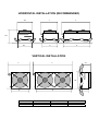
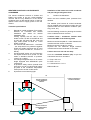
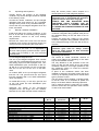
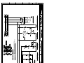
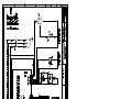
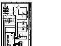
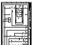
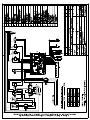
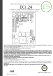
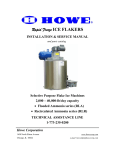
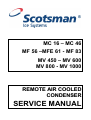
MC 16 – MC 46
MF 56 –MFE 61 - MF 83
MV 450 – MV 600
MV 800 - MV 1000
REMOTE AIR COOLED
CONDENSER
SERVICE MANUAL
HORIZONTAL INSTALLATION (RECOMMANDED)
450
A
A
622
B
383
B
VERTICAL INSTALLATION
A
314
A
408
B
180
B
A mm
B mm
1 FAN MOTOR
560
439
2 FAN MOTORS
1340
1139
3 FAN MOTORS
1980
1779
WEATHER PROOF AIR COOLED REMOTE
CONDENSER
Installation of the remote air cooled condenser
and pre-charged refrigerant lines
The remote condenser versions of Cubers and
Flakers are similar to the air cooled standard
versions with the only difference of the remote
condenser and, on MC and MF series, of the Fan
Speed Control used to supply power to the fan
motor/s.
A.
Select the best available place protected from
dirt/dust.
The weather proof remote air cooled condenser
can be installed indoor as well as outdoor and can
operate under the most different conditions (rain,
wing, snow, etc.)
Technical specifications
1.
Remote air cooled condenser fit on proper
brackets for horizontal and vertical
installation (MV series for vertical
installation only).
Cooling capacity with ∆T 15K is 3750
Kcal/hr on MC 16, MC 46 and MF 56 and
on MV 450, MV 600 and MV 1000 old
style; 9000 Kcal/hr on MFE 61; 17700
Kcal/hr on MF 83.
Fan motor/s 220-240/50-60/1 - 135 Watts
- 0,6 Amps with IP 44 protection (against
liquids and solids) and flow rate of 2150
m³/hr (2 motors on MFE 61; 3 motors on
MF 83).
On MC and MF series only, an Electronic
Fan Speed Control set to 16 bar. On MV
series a standard ON-OFF hi pressure
control (15÷17 bars).
Pre-charged refrigerant lines of 10 meters
length equipped with AEROQUIP quick
connections.
Hi pressure safety control (manual reset
type) set to 34 bar on MC and MF series
(in place of the condenser temperature
sensor) and to 30 bar on MV series.
Hi pressure control warning light.
2.
3.
4.
5.
6.
Location considerations:
Use the following formula for planning the location
of the condenser and ice machine.
Location Limits – Condenser location must
not exceed ANY of the following limits
Maximum vertical drop dd of 1 meter between the
icemaker and the remote condenser.
Maximum vertical rise rd of 3 meters.
Physical line set maximum length between
icemaker and remote condenser is 10 meters.
Limit to max. one rise and one drop.
Limit the calculated distance (CD) as per the
Calculation formula to 18 meters.
A = Drop = dd x 6.6
B = Rise = rd x 1.7
C = Horizontal run = hd x 1
CD = A + B + C
hd
Remote Condenser
located ABOVE Ice
Machine
rd
dd
Remote Condenser
located BELOW Ice
Machine
Condenser Distance &
Location Schematic
B.
Unpacking and inspection:
Visually inspect the exterior of the shipping
container; any severe damage should be reported
to the delivery carrier.
Uncrate the remote condenser and pre-charged
refrigerant lines and inspect for any concealed
damage. Notify carrier of any cancealed damage.
Check that the pre-charged refrigerant lines are
intact, not kinked.
C.
Remote condenser installation
Install and attach the remote condenser to the
floor or to the wall of the building using methods
and practices conform to the local building
requirements.
Remove the control box cover from the remote
condenser and connect the electrical power line
coming from the unit following the wires colors.
keep the excess portion indoor shaped as a
vertical spiral so to avoid refrigerant trapping.
CAUTION. Each coupling on the pre-charged
refrigerant lines is self-sealed and should be
tightened 1/4 turn more then snug tight.
ALWAYS USE TWO WRANCHES WHEN
TIGHTENING THESE FITTINGS, ONE AS
BACKUP WRENCH TO PREVENT TWISTING
OF TUBING AND POSSIBLE KINKING OR LINE
RUPTURE.
Connect the gas line coupling to the remote
condenser refrigerant fitting (labeled GAS) and to
the refrigerant fitting on the rear side of the ice
machine.
Connect the liquid line coupling to the remote
condenser refrigerant fitting (labeled LIQUID) and
to the refrigerant fitting on the rear side of the ice
machine.
NOTE. Cable connecting the unit to the remote
condenser is at 230 Volts so it is imperative to
have the cable properly protected inside a plastic
or metal tube according to the local electrical
code/standard.
ATTENTION. The inlet of the remote air cooled
condenser (gas) must be always located
above the outlet (liquid) for both horizontal
and vertical installations.
D. Pre-charged refrigerant lines
The remote air cooled condenser versions of
Cubers and Flakers are operating in the same
way as the standard machine.
The only difference is the operation of the fan
motor on MC and MF series as on the remote
condenser versions it is no longer possible to use
the condenser sensor to control the ON-OFF
operation of the same.
In place of the condenser sensor has been
installed an electronic fan speed control (set up at
16 bar by its adjusting screw) and a manual reset
type hi pressure control.
The fan speed control supplies a variable power
to the fan motor so to modulate its speed and
keep to a constant value the discharge pressure.
The hi pressure control is used only as a safety
device to switch OFF the operation of the machine
in case of fan motor failure.
The set of pre-charged refrigerant lines consists
of the 3/8" O.D. self sealing gas line and 1/4" O.D.
self sealing liquid line both equipped with 1-20"
UNEF AEROQUIP quick connections on MC 1646, MF 56, of 12 mm and 8 mm O.D. on MV 450600 and 14 mm and 12 mm O.D. on MV 8001000.
On models MFE 61 the pre-charged refrigerant
lines are 1/2" O.D. gas line and 3/8" O.D. liquid
line both equipped with 1-20" UNEF AEROQUIP
quick connections.
On model MF 83 only, 16 mm O.D. gas line and
12 mm O.D. liquid line with AEROQUIP quick
connections too.
Whenever the length of the pre-charged
refrigerant lines are longer then the distance
between the ice maker and the remote condenser
Remote air cooled condenser & fan motor assy
Fan motor assy - LU.VE.-CONTARDO
Fan motor assy - ECO
Hi pressure control (safety)
Fan speed control/Electronic device
Fan pressure control
Low pressure control
Liquid receiver
AEROQUIP male connection - LIQUID
AEROQUIP female connection - LIQUID
AEROQUIP male connection - GAS
AEROQUIP female connection - GAS
Operating instructions
MC 16-46
MF 56
MV 450-600-1000
OLD STYLE
MFE 61
MF 83
620418 00
001028 30
001028 32
620498 00
620500 00
*****
*****
*****
650438 01
650437 01
650438 01
650437 01
620418 00
001028 30
*****
620231 01
*****
CM 19550624
*****
CM 19635339
650438 01
650437 01
650438 01
650437 01
620418 01
001028 30
001028 32
620498 00
620500 00
*****
*****
*****
650438 00
650437 00
650438 00
650437 00
620418 02
*****
001028 32
620498 00
620500 00
*****
620451 00
*****
650438 00
650437 00
650438 05
650437 05
BIN FULL
SENSOR
SENSORE
SENSORE
TEMP. COND. CONT. PIENO
COND. TEMP.
SENSOR
SENSORE
TEMP. EVAP.
EVAP. TEMP.
SENSOR
SCK1
POMPE
ACQUA
WATER
PUMPS
ELETTROVALVOLE
GAS CALDO
HOT GAS
VALVES
FAN
MOTOR
VENTILATORE
HI PRESSURE
SWITCH
PRESSOSTATO
DI ALTA
WATER DISCHARGE
VALVES
ELETTROVALVOLE
SCARICO ACQUA
ELETTROVALVOLE
INGRESSO ACQUA
WATER INLET
VALVES
FOR MC46
PER MC46
COMPRESSOR
RESISTENZA COMPRESSORE
CRANCKCASE HEATER
COMPRESSORE
BIN FULL
SENSOR
SENSORE
SENSORE
TEMP. COND. CONT. PIENO
COND. TEMP.
SENSOR
SENSORE
TEMP. EVAP.
EVAP. TEMP.
SENSOR
SCK1
POMPE
ACQUA
WATER
PUMPS
ELETTROVALVOLE
GAS CALDO
HOT GAS
VALVES
FAN
MOTOR
VENTILATORE
HI PRESSURE
SWITCH
PRESSOSTATO
DI ALTA
WATER DISCHARGE
VALVES
ELETTROVALVOLE
SCARICO ACQUA
ELETTROVALVOLE
INGRESSO ACQUA
WATER INLET
VALVES
MODEL WITHOUT NEUTRAL
PER I MODELLI SENZA NEUTRO
FOR MC46
PER MC46
COMPRESSOR
RESISTENZA COMPRESSORE
CRANCKCASE HEATER
COMPRESSORE
HL5
HL4
HL3
HL2
HL1
FSC1
FC1
F1
EV3
EV2
EV1
Spia interruttore bocchetta
Spout switch light
Allarme mancanza acqua
Water alarm
Allarme bassa pressione
LOW pressure alarm
Allarme alta pressione
HI pressure alarm
Macchina in funzione
Power ON
Fan Speed
Fan Speed
Interruttore bocchetta
Spout switch
controllo sequenza fasi
3-phase monitoring relay
Ventilatore
FAN motor
Ventilatore
FAN motor
Ventilatore
FAN motor
M1
KT2
KT1
KM2
KM1
KA3
KA1
HL9
HL8
HL7
HL6
Compressore
Compressor
Ritardatore motoriduttore
Drive-motor timer delay
Ritardatore compressore
Compressor timer delay
Teleruttore motoriduttore
Drive-motor contactor
Teleruttore compressore
Compressor contactor
Relè anticipata motoriduttore
Drive-motor start relay
Relè amperometrico motoriduttore
Current drive-motor relay
Allarme protezione termica compressore
Compressor thermal protector alarm
Allarme amperometrica motoriduttore
Current drive-motor alarm
Allarme sequenza fasi
Wrong phase alarm
Magazzino pieno
Bin full
TM1
TM1
ST1
SP4
SP3
SP2
SB1
SA1
R1
M2
Protettore termico compressore
Compressor thermal protector
Relè protezione termica compressore
Compressor thermal relay
Termostato
Thermostat
Pressostato basa pressione
LOW pressure control
Controllo bassa pressione acqua
Water pressure control
Pressostato sicurezza alta pressione
HI pressure control safety
Pulsante reset
Reset push button
Interruttore
Switch
Resistenza compressore
Cranckcase heater
Motoriduttore
Drive motor