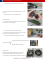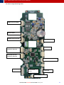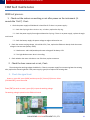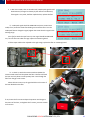
1
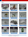
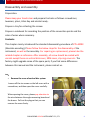
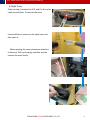
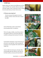
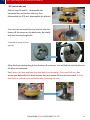
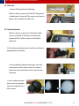
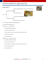
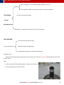
2010
KTS- 440RC SERIES
TOTAL STATION
SERVICE MANUAL
GUANGDONG KOLIDA INSTRUMENT CO., LTD.
KOLIDA
2010-10-20
1
KTS – 440RC SERIES TOTAL STATION SERVICE MANUAL
Tools
Oscillograph
Multimeter
Collimator
Screw driver
Pliers
Allen Key
Polishing Sticks
Cotton
Alcohol with ether
Green Grease
Tweezers
Lubricant
GUANGDONG KOLIDA INSTRUMENT CO., LTD.
1
2
KTS – 440RC SERIES TOTAL STATION SERVICE MANUAL
Disassembly and assembly
Preparation:
Please keep your hands clear and prepare the tools as follows: screwdriver,
tweezers, pliers, Allen Key and alcohol ready.
Prepare a tray for collecting the screws.
Prepare a notebook for recording the position of the connection points and the
color of wires when necessary.
Contents:
This chapter mainly introduced the standard disassembly procedure of KTS-440RC.
(Absolute encoding), Please follow the below steps for the disassembly of the
instrument, as well as the assembly. For repairing or replacement, please take the
related chapter as reference. After assembly, all screw should be coated with
varnish except those on vertical disk cover, EDM cover, slip-ring cover etc. The
factory might upgrade some of the spare parts, if you find some differences
between this manual and the instrument, please contact us.
Step:
1.
Remove the cover of vertical disc system
Loosen off the six screws on the left cover with a
screwdriver, and then open the cover carefully.
When opening the cover, please pay attention to
the wire between the angle-measuring board and
the buzzer. Pull out the plug so that you can
remove the cover freely.
GUANGDONG KOLIDA INSTRUMENT CO., LTD.
2
3
KTS – 440RC SERIES TOTAL STATION SERVICE MANUAL
2.
LCD Panel
Remove the LCD Panel carefully after Loosening off
the six screws
Before removing the LCD Panel, please be careful
the flat cable on the back. First open the flat cableclamp on the direction of red arrow, and then pull
out the flat cable, both of the LCD and the flat cable
are fragile, please be careful. Loosen off the four
screws on the LCD BACK COVER with a Screwdriver
and then remove it.
Open the flat cable-clamp on the direction of red arrow, and then pull out the flat cable on
the angle-measuring board carefully.
3. Angle-measuring board
It is same as the step 1: remove the cover, loosen
off the four screws on the angle-measuring board.
Pull out the plugs carefully, and record the position
of each plug for assembly. Please keep the anglemeasuring board appropriately and safely.
GUANGDONG KOLIDA INSTRUMENT CO., LTD.
3
4
KTS – 440RC SERIES TOTAL STATION SERVICE MANUAL
4. Right Cover
Refer to step 2, remove the LCD, and Cut the nylon
cable tie with pliers. Do not cut the wires.
Loosen off the six screws on the right cover and
then open it.
When opening the cover, please pay attention
to the wire. Pull out the plug, and then you can
remove the cover freely.
GUANGDONG KOLIDA INSTRUMENT CO., LTD.
4
5
KTS – 440RC SERIES TOTAL STATION SERVICE MANUAL
5.EDM Cover
Loosen off the four screws on the EDM cover and then
remove the EDM cover carefully. Make sure that the
telescope tangent screw is locked up in case of scuffing
the instrument when you loosen those screws.
6. Distance-measuring board
Set the instrument telescope in reversed
position, and then remove the cover on top of
the EDM.
Loosen off the four screws on the distancemeasuring board with a screwdriver.
Pull out the plugs carefully; record the position of
each plug for reference. Pull out the signal plug
carefully according to the direction of red arrow.
Finished those steps above, reverse the board, you
will see the receiving fiber is still connected with
the distance-measuring board. Be careful with the
fragile fiber.
Loosen a little the small screw on the top of the
receiving fiber base with Allen key, then pull out
the fiber carefully, and remove the main board.
GUANGDONG KOLIDA INSTRUMENT CO., LTD.
5
6
KTS – 440RC SERIES TOTAL STATION SERVICE MANUAL
7. Fibers
We applied forficate fiber in the KTS-440 series. As shown in the following figure, there is a
mixed-receiving end and which divides into two fibers; one is for inside path receiving, the
other for outside path receiving.
Mixed-receiving end
Inside path receiving fiber
Outside path receiving
fiber
Refer to step 5, 6. Remove both covers of EDM and the distance-measuring board. On one
side with motors and receiving fiber, you can find a small screw; loosen it a little till you can
pull out the inside path fiber. As shown in figure.
Turn the EDM over; loosen off the four screws on the metal cover, and pull the fiber out
carefully from the hole in the middle of the metal board.
Outside path fiber
base
GUANGDONG KOLIDA INSTRUMENT CO., LTD.
6
7
KTS – 440RC SERIES TOTAL STATION SERVICE MANUAL
As shown in figure, loosen a little the small screw
and then pull out the outside path fiber, till now we
remove the whole fiber. Since the fiber is very
easily broken, please keep it appropriately and
safely.
8. Vertical absolute encoding disc systems
Refer to step 1 and 3, remove the vertical disc
cover and the angle measuring board. Loosen off
the 4 screws in “A” area and the other 4 in “B”
area. Now you can take off the vertical disc dust
cover.
Loosen off the 4 screws in “C” area and the other
3 in “D” area.
In the red circle area,
there are 4 black flat
head CCD holding screws.
Do not loosen them when
remove the vertical disk.
B
A
c
D
GUANGDONG KOLIDA INSTRUMENT CO., LTD.
7
8
KTS – 440RC SERIES TOTAL STATION SERVICE MANUAL
Fallow the steps to assemble the Vertical absolute
encoding disc system:
Assemble the two vertical angle CCD sensor first.
Attention to this little triangle mark on the edge of
the vertical disc, this is the 0° angle mark.
As shown in figure, set the telescope in normal, assemble the vertical disk system into the
appropriate position carefully. Align the holes for screws between the EDM and the vertical
disk, and at the same time make sure the small triangle mark is near by the lower CCD. This
is very important, if the triangle mark is not in the right position after assembling the disk
system, the vertical angle-value reading will be wrong.
Tighten all the screws when finished those steps above. And do not forget the washer
during assembling.
GUANGDONG KOLIDA INSTRUMENT CO., LTD.
8
9
KTS – 440RC SERIES TOTAL STATION SERVICE MANUAL
9.Vertical CCD unit
Refer to step 1, 3, 8, remove the vertical disk
cover,Distance measuring board and vertical disk
system. Loosen off the 4 screws to disassemble the
CCD unit. With the same way, remove another one
in the opposite position.
10. CCD Bracket
Refer to step 1, 3, 8, and 9, remove vertical disk
cover, angle-measuring board, vertical-disk system,
and vertical CCD unit. Then turn over the vertical
disk, there is a copper nut, loosen it off with pliers.
Take out vertical disc from bracket. Please keep
them appropriately and safely.
11. Vertical tangent screw
Refer to step 4, remove the slip-ring cover. Loosen a little the two small screws with Allen
key. Press the end of vertical brake-ring system according to the direction of red arrow, at
the same time pull out the vertical tangent screw carefully.
GUANGDONG KOLIDA INSTRUMENT CO., LTD.
9
10
KTS – 440RC SERIES TOTAL STATION SERVICE MANUAL
12. Slip-ring
Refer to step 1, remove the vertical disk cover
and disconnect the slip ring plug form the angle
measuring-board. Refer to step 2, remove the
LCD on Left side and the back cover. Refer to
step 4, cut the cable tie and pull out the slip ring
wire. Then loosen off the two screws as shown
in figure.
Refer to step 6. Pull out the 4-pin slip ring plug
from the distance measuring board. Record the
color and the position of each wire then pull
them out carefully with tweezers, please keep
the plug appropriately and safely.
Loosen off the 3 screws as shown in figure then pull out the slip-ring unit.
3.
4.
5.
6.
13. Vertical brake-ring
Refer to step 4, 11, and 12, remove the slip-ring cover, telescope tangent screw, and
the slip ring. Loosen off the 3 screws as shown in figure, and remove the vertical brake
ring .
GUANGDONG KOLIDA INSTRUMENT CO., LTD.
10
11
KTS – 440RC SERIES TOTAL STATION SERVICE MANUAL
14. Axle sleeve
Refer to step 4, 10, 11 and 12, remove the slip-ring cover, vertical telescope tangent screw,
slip ring, and the vertical arresting gear ring. Loosen off the 4 screws as shown in figure,
hold the EDM, and pull out the axle sleeve with your hands. If it is blocked, do not force to
remove the axle sleeve, please send the instrument back to the factory.
15.EDM
Refer to step 1-14, turn the EDM to reverse position, hold the EDM with both of your hands,
and take it out according to the direction of red arrow. Be careful, do not drop the EDM.
GUANGDONG KOLIDA INSTRUMENT CO., LTD.
11
12
KTS – 440RC SERIES TOTAL STATION SERVICE MANUAL
16. Compensator
Refer to step 1 and 4, remove the vertical disk
cover, compensator plug on the angle measuring
board, left side LCD and back cover, then cut the
cable tie, pull out the compensator wire, open the
slip ring cover.
Loosen off the 2 screws as shown in figure, then you can take out the compensator freely.
17. Horizontal tangent screw
Refer to step 2, remove the right side LCD and back cover.
Loosen the two little screws with Allen key; press the end of horizontal brake ring system
according to the direction of red arrow, at the same time pull out the tangent screw
carefully.
18. Horizontal disc and vertical axle unit
Refer to step 1, 2, 3, 4, 5, and 17, remove the vertical disk cover, slip ring cover, both of the
LCDs and back covers, cut off the cable tie, and pull out the CCD plugs, remove one EDM
cover and the horizontal tangent screw.
Take off the 4 rubber cover.
Loosen off the 3 screws with Allen key.
Disassemble the tribrach.
GUANGDONG KOLIDA INSTRUMENT CO., LTD.
12
13
KTS – 440RC SERIES TOTAL STATION SERVICE MANUAL
Turn over the instrument and loosen off the screws
on the back cover.
Use Allen key to loosen off the 3 base holding screws, and then take off the base, then
loosen off the 6 dust cover holding screws and take off the dust cover.
Hold the instrument body with both of your hands, and then move it up carefully. Pay
attention to the horizontal brake ring system, and the CCD wire.
19. Horizontal CCD unit
Refer to step 18, disassemble the horizontal disc
and vertical axle unit, loosen off the screws on the
CCD unit, then you can remove the CCD unit.
GUANGDONG KOLIDA INSTRUMENT CO., LTD.
13
14
KTS – 440RC SERIES TOTAL STATION SERVICE MANUAL
20. Vertical axle unit
Refer to step 18 and 19, , disassemble the
horizontal disc and vertical axle unit, then
disassemble the CCD unit, disassemble the tribrach.
Turn over the horizontal disc and vertical axle unit;
loosen off the screws on the back cover. Be careful
with the horizontal angle disc.
Loosen off the copper nut with
Allen key.
Move the base up according to the direction of red arrow. You will find the vertical axle and
the base are separated.
Tips: upturn the base and keep the steel balls from dropping. If any steel ball lost, the
whole steel balls will fail to work because they are unique set for each instrument. Put the
steel bolls in a container immediately after removing the axle
GUANGDONG KOLIDA INSTRUMENT CO., LTD.
14
15
KTS – 440RC SERIES TOTAL STATION SERVICE MANUAL
21. Plate vial
Loosen off the plate vial adjusting.
Refer to step 3, remove the left LCD along with
its back cover, loosen off the screws as shown in
figure, then remove the plate vial.
22. Optical plummet
Refer to step 3, remove the LCD and its back
cover on the left of slip-ring. Use Allen key
loosen off the 2 little screws on the Optical
plummet.
Pull out the optical plummet carefully, and keep it
appropriately and safely.
The assembling of optical plummet: level the
instrument on the tripod, insert the optical
plummet to the instrument then look into the
eyepiece.
Turn the plummet until
you can see a complete
view, then tighten the 2
little screws.
GUANGDONG KOLIDA INSTRUMENT CO., LTD.
15
16
KTS – 440RC SERIES TOTAL STATION SERVICE MANUAL
23. Eyepiece and cross hair
Screw off the eyepiece cover and the eyepiece. By loosening off the four screws inside, you
can remove the cross hair freely.
Summary: This is the disassemble process of KTS-450RC series, however, the disassemble
instruction for some components are not mentioned here, such as: luminotron, motor, the
inside path prism, telescopic tube etc. As the most of them could not be assembled without
special tools, we suggest you do not try to dissemble them by yourself
GUANGDONG KOLIDA INSTRUMENT CO., LTD.
16
17
KTS – 440RC SERIES TOTAL STATION SERVICE MANUAL
Common problem for angle measuring
Error code 1 - 7
Adjusting the gap between copper nut and axle sleeve
Mechanical failure
Tighten Center screw
Error 1
Horizontal CCD (adjusting or replace)
Electronic failure
Replace angle measuring board
Error 2 telescope rotated too fast (protecting error)
Error 3 Main body rotated too fast.
Error 4, Error 7
Vertical CCD unit
A: bad signal (adjusting the signal)
B: dust on disc (clean the disc)
C: CCD unit broken, or dust on the surface of CCD (replace or clean)
D: Sun radiation on the disc.
E: Main board broken.
ERROR 5, Error 6
Horizontal CCD unit
A: bad signal (adjusting the signal)
B: dust on disc (clean the disc)
C CCD unit broken, or dust on the surface of CCD (replace or clean)
D: Sun radiation on the disc.
E: Main board broken.
GUANGDONG KOLIDA INSTRUMENT CO., LTD.
17
18
KTS – 440RC SERIES TOTAL STATION SERVICE MANUAL
Battery voltage< 5.5 V. the working voltage should be: 5.5v-7.5v
Battery
Check the power supply wire inside the right cover and the weld point.
No display
The LCD unit and the flat cable.
or can
not power on
Mainboard: Programming error (CPU), return it to the factory.
Axle blocked
Dust inside axle sleeve (clean dust)
Vertical axle blocked
Axle (Rusty, Moldy, Tilt) (polishing)
The gap between copper nut and axle sleeve (fix gap)
Polishing process:
When the vertical axle blocked, please do not try to rotate the instrument, otherwise it will damage the vertical axle
and axle sleeve.
Steps:
(1)Refer to step 1-20 in dissembling chapter, take out the vertical axis.
(2)Clean the lubricant on the vertical axle.
GUANGDONG KOLIDA INSTRUMENT CO., LTD.
18
19
KTS – 440RC SERIES TOTAL STATION SERVICE MANUAL
((3)Daub polishing powder (Green grease) on the vertical axle.
(4)Set the polishing tool on the vertical axle then rotate it 2-3 rounds
clockwise.
(5)Take out the axle, and clean the polishing powder.
Polishing axle sleeve.
(6)Daub polishing powder on the polishing stick then put it into the axle
sleeve and rotate it 2-3 rounds clockwise.
.
(7)Take out the polishing stick and clean the axle sleeve.
(8)Assemble the axle and axle sleeve (base unit). If the axle can rotate
smoothly, that means the polishing process succeeds.
(9)If the vertical axle still blocked, please repeat the steps 2-8.
Axle and axle sleeve position changed (fix position)
Horizontal axis blocked
Axle (Rusty, Moldy, Tilt) (polishing)
Polishing process:
When the horizontal axle blocked, please do not try to rotate the
telescope, it will damage the horizontal axle and axle sleeve.
1)Refer to step 10 in dissemble chapter. Disassemble the horizontal
GUANGDONG KOLIDA INSTRUMENT CO., LTD.
19
20
KTS – 440RC SERIES TOTAL STATION SERVICE MANUAL
axle and axle sleeve.
(2)Clean the lubricant on the horizontal axle.
(3)Daub polishing powder (Green grease) on the horizontal axle.
(4)Set the polishing tool on the horizontal axle then rotate it 2-3 rounds
clockwise.
(5)Take out the axle, and clean the polishing powder.
Polishing axle sleeve.
(6)Daub polishing powder on the polishing stick then put it into the axle
sleeve and rotate it 2-3 rounds clockwise.
(7)Take out the polishing stick and clean the axle sleeve.
(8)Assemble the axle and axle sleeve. If the axle can rotate smoothly, that
means the polishing process succeed.
(9)If the horizontal axle still blocked, please repeat the steps 2-8.
Display unit
One display unit failure may leads both of two displays fail to work. Please change it one by one to find out which one is
broken.
Communication port fault maintenance
Make sure the communication cable is good and connection between computer and TS is steady. The
communication port is well connected with the mainboard.
And check the baud rate. If the fault still can not be ruled out, please change the main board.。
GUANGDONG KOLIDA INSTRUMENT CO., LTD.
20
21
KTS – 440RC SERIES TOTAL STATION SERVICE MANUAL
The name for angle-measuring board
Upper CCD unit socket
Buzzer socket
Bottom CCD unit socket
Slip-ring socket
COM socket
Horizontal CCD unit
socket for short wire
Horizontal CCD unit
socket for short wire
Compensator socket
LCD socket
short wire
口
SD card cable
socket
LCD socket
Power supply socket
GUANGDONG KOLIDA INSTRUMENT CO., LTD.
21
22
KTS – 440RC SERIES TOTAL STATION SERVICE MANUAL
EDM fault maintenance
EDM test process:
1.Check out the motors are working or not after power on the instrument. (It
sounds like “click”). If not:
1.Check the power supply to EDM board. It should be 6V. if there is no power supply:
(1)check the slip ring is short circuit or not, or broken, replace the slip ring.
(2)check the power supply from angle mainboard to slip ring. If there is no power supply, replace the angle
main board.
(3)check the battery supply the power voltage to angle mainboard or not.
2.Check the motors working voltage, it should be 2.5V, if not, replace the EDM main board, check the motors
voltage in the test state (factory mode).
(1)Mode motor and inside/outside path motor voltage will be always 2.5V.
(2)Test light Reduce motor when it is working.
3.Check whether the motor is broken or not. If broken, replace a new one.
2.Check the laser comes out or not, if not:
The emitting tube working voltage should be 3v. If there is no power supply from measuring board to emitting
tube, replace the measuring board. If the power supply is good, then replace the emitting tube.
3.Check the signal level:
Power on, press ESC, press [CNFG] and then press [F1] 5 times [F4] 3 times. Select
[F2 EDM STATE], enter test mode.
Press [FNC] to switch to state 3, press [F2] to input the working voltage.
The working voltage is pasted on the EDM main board.
GUANGDONG KOLIDA INSTRUMENT CO., LTD.
22
23
KTS – 440RC SERIES TOTAL STATION SERVICE MANUAL
2 In Non-Prism mode, shot on the white wall, outside path signal should
be 80-150 mv (The signal is relativity by the reflector and distance.)
If the signal is very weak, the fiber maybe broken, replace the fiber.
(3)Inside path signal should be 1000-1500 mv.(Prism or Non-Prism
mode) if not, loosen the inside filter holding screw near the fiber. Turn the
inside path filter to change the signal; tighten the screw when the signal in the
working range.
Press [F4] to switch the tape from 0-5, their signal should be 1000-1500
mv, if one of them not under the rage, replace the measuring board.
If all the tapes could not be adjusted to the right range, replace the fiber or measuring board.
(4)In STATE 1, switch the measure mode to PRISM. The
measure mode motor will drop down the filter. The filter will block
the laser and only allows a small quantity laser come through the
filter from the gap in the center.
When the laser comes out, the gap should be in the center of
the laser blocked on the filter.
If not, loosen the fix screws to adjust the position until the gap in
the center of the laser, and tighten the fix screws, put some varnish
on fix screws.
GUANGDONG KOLIDA INSTRUMENT CO., LTD.
23
24
KTS – 440RC SERIES TOTAL STATION SERVICE MANUAL
4.Check and Adjust 3 axis.(before adjust 3 axis, make sure 2C is correct. Refer to total
station Calibration the 4th section)
3 axes: sight axis, emitting axis, receiving axis. (The 3 axis should be match together, if not, it will cause the instrument can
not measure long distance.
1.check and adjust Emitting axis
(1)Set the total station on the tripod and level it. Put a crosshair-board 50 Meter away from total station. Turn on the
instrument, enter the test mode. Select Non-Prism in State 1 to let the laser comes
out from the Lens center.
(2)Set up a theodolite beside the total station. Use for observe the laser dot on
the crosshair-board.
(3)Match the two crosshairs together between TOTAL STATION and
crosshair-board.
(4)Adjust screw 1,2 which on the base board to move the laser point to the
left or right. loosen screw 3,4 then turn the redirection mirror to move the
laser point up or down, until the laser dot in the center of the crosshair.
1,2
3,4
Redirection mirror
Focus Prism
Holding SCREW
(5)loosen the holding screw then Turn the focus prism clockwise to make laser
point focus. Tight the holding screw.
GUANGDONG KOLIDA INSTRUMENT CO., LTD.
24
25
KTS – 440RC SERIES TOTAL STATION SERVICE MANUAL
2. Check and adjust Receiving axis
Check the receiving axis to see if it is matched together with the sight axis.
if not, adjust the receiving fiber base.
Refer to Chapter: disassembly step 6,7, pull out the mix-receiving end from
the measuring board.
Focus the total station to infinity.
As shown in figure, use a theodolite aim at the total station lens, turn the
theodolite zoom ring utill you can see total station crosshair clearly.
Aim the mix-receiving end to a light.
As shown in figure, we can see a light dot through the theodolite eyepiece.
If you can not see the light dot, you need to adjust the outside path receiving fiber to
Focus the light dot until you can see it clearly.
Loosen the outside path receiving fiber holding Screw,
Move the fiber up and down to focus the light dot, when finished,
Tighten the holding screw.
Loosen three screws on the fiber base as shown in figure. Move the fiber
base to make the light dot in the center of the total station crosshair.
Finally, tighten those screws and put varnish on them.
GUANGDONG KOLIDA INSTRUMENT CO., LTD.
25
26
KTS – 440RC SERIES TOTAL STATION SERVICE MANUAL
5. Test Point on the EDM Board
Emitting Fiber signal
and Power supply
plug.
1,the socket and plug on the EDM board:
Slip ring
socket
3 Motors Power
Supply socket
forficate fiber mixreceiving end socket
Optical coupling unit
socket
GUANGDONG KOLIDA INSTRUMENT CO., LTD.
26
27
KTS – 440RC SERIES TOTAL STATION SERVICE MANUAL
2, EDM board test point
Working voltage test point, same as the sticker on the EDM
board (this board is 173.2V)
Power supply for measure
tape
Working voltage is 4.9v
CPU power supply 3.6V
Battery Power supply 6V.
Emitting fiber working
voltage, 3.3V
Same as slip ring
GUANGDONG KOLIDA INSTRUMENT CO., LTD.
27
28
KTS – 440RC SERIES TOTAL STATION SERVICE MANUAL
6. Optical coupler
Optical coupler is used for estimating the distance between total station and target. The emitting and receiving diode
on the optical coupler are connected together and looks like a “U”. Make sure the black edge of the light filter inside the
“U”. (Emitting diode and receiving diode.)
GUANGDONG KOLIDA INSTRUMENT CO., LTD.
28
29
KTS – 440RC SERIES TOTAL STATION SERVICE MANUAL
Common faults and errors.
(1)
Outside path signal too weak, fiber broken or EDM board broken, replace fiber or EDM board
(2)
The measuring functions fail to work under Prism Mode, but pretty good under Non-prism mode. Fiber broken or EDM
board broken, replace fiber or EDM board
(3) At times, the instrument does work properly in Non prism mode. Inside path motor against with other parts, fix the
motor position. or EDM board broken, replace it.
(4)
The measuring function totally fails under Non-Prism mode. Check the fiber and upgrade the program, check the EDM
board.
(5)
Measure speed is slow. Upgrade the EDM program, connect the PC, Press F3 and power on, upgrade the program.
(6)
The instrument is failed to measure distance. Check the instrument step by step according this chapter.
(7)
Aim at the prism center, the instrument doesn’t shoot distance, offset the crosshair from the prism center, the
instrument start shoot distance.
The instrument only measure short distance, but doesn’t measure long distance.
Check and Adjust 3 axis
(8)
The measure result is not stable, inside path signal is too strong, adjust the signal according this chapter Check
the
signal level
GUANGDONG KOLIDA INSTRUMENT CO., LTD.
29
30
KTS – 440RC SERIES TOTAL STATION SERVICE MANUAL
Calibrations
Preparation:
Please prepare screw driver, adjusting pin, varnish, hexagon wrench, level the instrument on the collimator, wash
your hands and get ready.
Content:
This chapter mainly introduces you the standard adjusting process, the following steps should be finished on the
collimator. Except the adjustment of optical plummet, the other steps should follow the given order; otherwise you
can’t get the wrong result.
Process:
1.
C
Plate Vial
Level the instrument on the collimator. As shown in the figure, rotate
instrument, make plate level parallel in the center of leveling screw A and
B, and then adjusts leveling screw to make plate bubble centered.
A
B
C
Turn the instrument for 90 degrees, adjust the third leveling screw, and
make the plate bubble centered. Repeat the steps 1 and 2, make the plate
bubble centered in above two positions.
A
C
Rotate instrument 180°. If the plate bubble not centered, adjust the fix
screw, move the plate bubble a half of the difference;
A
GUANGDONG KOLIDA INSTRUMENT CO., LTD.
B
B
30
31
KTS – 440RC SERIES TOTAL STATION SERVICE MANUAL
2.
Circular Vial
After examining the plate bubble, circular bubble should be
centered too (or not beyond the reticle circularity), which
indicates the circular bubble is vertical to vertical axis. if not the
adjustment steps are as follows.
1.
Loosen the screw (one or two) opposite with bubble deflective direction;
2.
Tweak tightly the screw on the direction accordant deflective until circular bubble is centered;
3.
Adjust three adjustment screws for several times until circular bubble is centered;
4.
The force power fixing three adjustment screws must be consistent when circular level is centered at last.
3.
Cross Hair
Make sure the collimator crosshair is good. Try to match
the total station crosshair center and collimator crosshair
center together. If the two crosshair matched perfectly,
means the total station crosshair is good.
As shown in figure. If the total station crosshair is tilt, then
you have to calibrate it.
Take off the eyepiece cover, Loosen the three crosshair holding screws; move the crosshair base to
match the two crosshair together then Tighten screws, and then daub a little varnish on those screws.
GUANGDONG KOLIDA INSTRUMENT CO., LTD.
31
32
KTS – 440RC SERIES TOTAL STATION SERVICE MANUAL
4.
2C (Perpendicularity between Sight Axis and
Horizontal Axis)
Level the instrument; aim at the collimator, match the total
station crosshair with one of the horizontal scales on the
collimator crosshair.
And press “0set” (F1)
Reverse the telescope and aim at the same scale, and read
the horizontal angle value, which should be 180° ±8”. As
shown in the figure, the value of HR is 180°00’40”.
It means the 2C is +40”, we have to adjust it.
NTS-360R series total station has two way to calibrate 2C:
Solution 1: mechanical calibration
Turn the horizontal tangent screw to make the horizontal
angle value to 180°00'20" ---- half of the 2C value. See the
shown figure.
Look at the crosshair, the crosshair moved a little from the
scale (gray area), take off the eyepiece cover and adjust the left and right adjusting screws to make the
crosshair back to match the scale again. The principle is loosen one adjusting screw before tighten another.
After the adjustment, check the 2C again, if it still over ±8”, please do it again.
When 2C > 1’, it will affect the 3 axis. First, you have to fix the 2C, then check and adjust the 3 axis ,
otherwise it will affected the distance measurement.
GUANGDONG KOLIDA INSTRUMENT CO., LTD.
32
33
KTS – 440RC SERIES TOTAL STATION SERVICE MANUAL
Solution 2:Electronic calibration (only can use when 2C < 2’)
Press CNFG; choose [2.Instr, const]. Then choose [3. Collimation]
Level the instrument; aim at the collimator, match the total station crosshair with one of the horizontal
scales on the collimator crosshair.
Press [F4] choose ok, go to step 2
Reverse the telescope and aim at the same scale.
Press F4, the calibration process ends up with <SET!> on the screen.
GUANGDONG KOLIDA INSTRUMENT CO., LTD.
33
34
KTS – 440RC SERIES TOTAL STATION SERVICE MANUAL
5. High-low Difference (Perpendicularity between Horizontal Axis and Vertical Axis)
Inspection Steps and Criterion:
On the first position (main board is on your left side), aim at the horizontal collimator, match the total
station crosshair with one of the horizontal scales on the
collimator crosshair. As shown in figure.
Rotate the EDM, Aim at the lower collimator, note down the
intersection between total station crosshair and collimator
crosshair.
On the second position (main board is on your right side),
do the same procedure as above, note down the
intersection between total station crosshair and collimator
crosshair.
LEFT-HR
LEFT-LOW
RIGHT-HR
The difference between the two intersections is high-low
difference, which should be less than 10” (1 division on the
collimator is 30”)
RIGHT-LOW
Refer to Disassembly part 4,take off the right cover,
Loosen the four screws a little.(notice: DO NOT loosen too much)
According to the red arrow, move the axle sleeve up and down to
calibrate the high-low difference.
As shown in the figure, adjust the axle sleeve till the
crosshair move to the white line. (Half of the difference)
GUANGDONG KOLIDA INSTRUMENT CO., LTD.
34
35
KTS – 440RC SERIES TOTAL STATION SERVICE MANUAL
After high-low difference, the four screws should be tight to make sure the horizontal axis is steady, daub
some vanish on the screws, and do the plate vial calibration after.
6.
Compensator
Make sure the plate vial is good and level the instrument on the collimator, power on and press esc, you
can see the model, number and version of software.
Press [SFT] and [.] to enter the compensator calibration
program.
The figure shows the electronic bubble position.
Press [DIGIT] to see the electronic bubble offset.
C
B
A
A
X direction calibration:loosen two screws in A area a little,knock the left and right side of the compensator,
make the X = 0°00'00", then tighten the screws.
Y direction calibration:loosen screw C,turning screw B, until Y =0°00'00", then tighten the screws.
GUANGDONG KOLIDA INSTRUMENT CO., LTD.
35
36
KTS – 440RC SERIES TOTAL STATION SERVICE MANUAL
7.
I Angle (Vertical Angle Index error)
Level the instrument and aim at the collimator (first
position), as shown in figure, match the total station
crosshair with one of the vertical scales on the collimator
crosshair.
As shown in the figure the V1 is 90°00’00”.
Reverse the telescope and aim at the same scale, note down
the vertical angle value.
As shown in figure the V2 is 270°00’50”.
I angle = (v1+v2 -360°)/2. I angle should < ± 6”. Otherwise
we have to calibrate it.
Press CNFG; choose [2.Instr, const] to enter the calibration
program.
Press F2 selects V0 Adjustment.
Level the instrument on the collimator (first position), aim at the collimator as shown in figure, and match
the total station crosshair with one of the vertical scales on the collimator.
GUANGDONG KOLIDA INSTRUMENT CO., LTD.
36
37
KTS – 440RC SERIES TOTAL STATION SERVICE MANUAL
Press F4 and enter the next step.
Reverse the telescope, aim at the collimator as shown in figure, and match the total station’s crosshair with
the same vertical scales on the collimator.
Press F4, the calibration process ends up with <SET!> on the
screen.
When the Index error is too big to adjust, the system will
remind you for mandatory setting after the above steps were
done. Press F4 to select OK.
After mandatory setting, you should check the index error
again according to the above steps.
GUANGDONG KOLIDA INSTRUMENT CO., LTD.
37
38
KTS – 440RC SERIES TOTAL STATION SERVICE MANUAL
8.
Optical Plummet
Inspection Steps and Criterion
Place a picture of crosshair underneath the tripod after the
instrument was settled on the tripod. Move the paper until the
crosshair overlaps the center of plummet
Rotate the instrument every 90° to check whether the center
of optical plummet is right above the crosshair center
If not, rotate the instrument for 180°, and examine the
optical plummet center offset distance.
Usually, adjust the center of optical plummet halfway to the
crosshair center with adjusting pin.
As shown in the figure: Take down the optical plummet
eyepiece cover, and adjust the four screws inside.
As show in the picture, through moving the optical plummet to the center of red crosshair, the gap will be
reduced by half. Then, overlap the optical plummet and the crosshair which drawn on the paper. If the
gap still exists, repeat the above steps until it disappears
GUANGDONG KOLIDA INSTRUMENT CO., LTD.
38