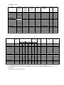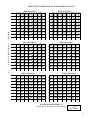
1
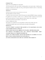
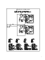
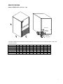
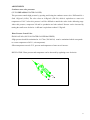
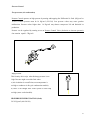
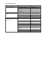
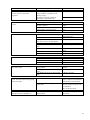
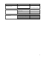
WHIRLPOOL (R404a)
TECHNICAL SERVICE MANUAL
ICE CUBE MAKERS
MODELS:
WHIRLPOOL AGS 836/837
WHIRLPOOL AGS 838/839
WHIRLPOOL AGS 840/841
WHIRLPOOL AGS 842/843
WHIRLPOOL AGS 844/845
WHIRLPOOL AGS 846/847
WHIRLPOOL AGS 848/849
MODULARS:
WHIRLPOOL AGS 850/851 (MODULAR 200)
CAREFULLY READ THE INSTRUCTIONS CONTAINED IN THIS MANUAL SINCE THEY
PROVIDE IMPORTANT INFORMATION RELATIVE TO SAFETY DURING INSTALLATION,
USE, AND MAINTENANCE.
EDITION:
NOVEMBER 2006.
COD: WHP02MTIN.DOC
1
TABLE OF CONTENTS
Introduction
Warnings............................................................................................................................................................ 3
Description......................................................................................................................................................... 4
Operating Principles........................................................................................................................................... 5
Specifications
Diagrams of connections and dimensions (undercounter models) ..................................................................... 6
Consumption data, weights, crated dimensions and volumes (undercounter models)........................................ 8
Technical data (undercounter models) ............................................................................................................. 10
Production Tables ............................................................................................................................................ 11
Delivery & Unpacking
Packing............................................................................................................................................................. 13
Rating plate and serial number......................................................................................................................... 13
Installation
Recommended placement of unit ..................................................................................................................... 14
Water and drainage .......................................................................................................................................... 14
Connecting unit to water source....................................................................................................................... 15
Connecting unit to drain................................................................................................................................... 15
Electrical connection........................................................................................................................................ 15
Operation principle
Preliminary check ............................................................................................................................................ 17
Cross check ...................................................................................................................................................... 17
Adjustment
Water level....................................................................................................................................................... 18
Water pressure control valve............................................................................................................................ 18
Pressure control................................................................................................................................................ 19
Safety pressostat............................................................................................................................................... 19
Maintenance and cleaning instructions
Maintenance table ............................................................................................................................................ 20
Water condenser .............................................................................................................................................. 21
Air condenser ................................................................................................................................................... 21
Evaporator / water deposit ............................................................................................................................... 21
Inlet filters........................................................................................................................................................ 22
Special advice concerning r-404 refrigerant .................................................................................................... 23
Troubleshooting ........................................................................................................................................................ 24
2
INTRODUCTION
Thank you for choosing Whirlpool ice cube makers.
You have purchased one of the most reliable ice-making products on the market today. Carefully read the
instructions contained in this manual since they provide important information relative to safety during
installation, use, and maintenance.
WARNINGS
This appliance should be installed by approved Technical Service Personnel.
This plug should be accessible at all times.
To reduce the risk of electrical shock, ALWAYS disconnect the machine BEFORE cleaning or maintaining
the equipment. Do not attempt to install, service, or modify this machine. Improper use by other than
specially trained technicians is extremely dangerous and may result in a fire or electric shock.
This machine should not be placed outdoors or exposed to rain.
Connect to drinking water mains.
This appliance is not intended for use by young children or infirm persons without supervision.
Young children should be supervised to ensure that they do not play with the appliance.
IMPORTANT!
• DO NOT ATTEMPT TO SERVICE THIS MACHINE AS IT IS DANGEROUS AND COULD
CAUSE SEVERE DAMAGE TO THE UNIT.
•SERVICE SHOULD ONLY BE CARRIED OUT BY TRAINED, CERTIFIED PERSONNEL.
•WE STRONGLY RECOMMEND USING ONLY ORIGINAL REPLACEMENT PARTS
AVAILABLE FROM AN AUTHORIZED DISTRIBUTOR.
•WASTE AND OTHER MATERIAL SHOULD BE DISPOSED OF ACCORDING TO LOCAL
REGULATIONS AND PROCEDURES FOR WASTE DISPOSAL.
•CLEANING AND MAINTENANCE ARE NOT COVERED BY THE WARRANTY.
3
DESCRIPTION
The ice cubes maker is the result of years of experience in this field and the development of a high
technology factory.
Main Features
•
Storage bin made of polyester strengthened with glass fibre or ABS
•
Stock bin made of high resistance plastic materials
•
Polyurethane insulation injected “IN SITU”
•
Heavy duty door (pat.) except AGS 836/837/838/839 and 850/851.
•
Agitator motor for continuous service
•
Tough cam motor (50 Kg/cm)
•
Safety device and clutch for the water pan preventing its breakage during the upward cycle, (pat.)
•
Machine stoppage and water pan protection during the downward cycle, (pat.)
•
The stock ice is the maximum than it could be thanks to the stop machine system.
•
Low noise
•
High pressure safety pressostats even in air-cooled machine.
•
Large condensers (work well at high ambient temperatures; and reduce cooling water consumption in
water-cooled machines).
•
Clear cubes.
•
Ices Cubes can be adjusted (height and diameter).
•
Easy to maintain and repair.
HOW IT WORKS
When the machine is switched on the compressor and the agitator motor start, the water entry valve opens
and allows water into the production pan up to a level where the float makes a micro-switch cut the current
to the valve and so stop water entering the tray. The compressor, controlled by capillaries produces enough
cold in the evaporator to gradually freeze the water around its “fingers”.
When the ice so formed reaches the proper size the paddles of the agitator are stopped and its motor,
suspended, works the end of cycle micro-switch.
This micro-switch connects the relay that starts the cam motor. When the micro-switch has fallen, opens the
hot gas valve and stops the agitator motor. The compressor continues working for another 20”, then stops,
and the agitator motor is connected. The cam motor starts to move downwards, making part of the surplus
water flow to the drain, and dropping the ice cubes, pushed by the ejection plate into the storage bin.
The pan eventually gets back to its initial position and so starts another production cycle.
Once the storage bin is full the pan stops in its downward movement as it touches the cubes, so working the
safety stop micro-switch and switching off the machine. Production will start again as soon as the cubes
which detained it move or are removed.
4
WHIRLPOOL
5
WHIRLPOOL AGS
6
SPECIFICACIONS
Models: WHIRLPOOL AGS 836….849
Water entry
Electrical
connection
Bin drain
Cooling water
* HEIGHT Z REPRESENTS MINIMUM MACHINE HEIGHT. IF LEGS ARE PLACED UNDER MACHINE, THEN ADD
AN EXTRA 80 MM.*
MODEL
WHP AGS 836/837
WHP AGS 838/839
WHP AGS 840/841
WHP AGS 842/843
WHP AGS 844/845
WHP AGS 846/847
WHP AGS 848/849
X
Y
Z
A
B
C
D
E
F
G
405
405
405
515
595
675
845
510
510
510
555
555
555
555
690
745
870
870
995
995
995
60
60
60
60
60
60
60
35
35
35
42
42
42
42
65
65
65
74
74
74
74
123
123
123
123
123
123
123
45
45
45
65
65
65
65
65
65
65
75
75
75
75
105
105
105
105
105
105
105
7
WHIRLPOOL AGS
850-851
ELECTRICAL CONNECTION
STOCK THERMOSTAT
WATER INLET
8
TECHNICAL DATA
MODEL
COOLING
WATER
USAGE
L/HOUR (1)
WHP AGS 836
WHP AGS 837
WHP AGS 838
WHP AGS 839
WHP AGS 840
WHP AGS 841
WHP AGS 842
WHP AGS 843
WHP AGS 844
WHP AGS 845
WHP AGS 846
WHP AGS 847
WHP AGS 848
WHP AGS 849
WHP AGS 850
WHP AGS 851
MODEL
WHP AGS 836
WHP AGS 837
WHP AGS 838
WHP AGS 839
WHP AGS 840
WHP AGS 841
WHP AGS 842
WHP AGS 843
WHP AGS 844
WHP AGS 845
WHP AGS 846
WHP AGS 847
WHP AGS 848
WHP AGS 849
WHP AGS 850
WHP AGS 851
ICE
PRODUCTION
WATER
USAGE
L/HOUR (1)
TOTAL
WATER
USAGE
L/HOUR (1)
NET
WEIGHT
4
4
4
4
5
5
7
7
6
6
23
23
11
11
11
11
4
19
4
19
5
30
7
40
6
41
8
68
12
64
11
81
36
36
39
39
42
42
48
48
55
55
60
60
80
80
98
98
15
15
25
33
35
45
53
70
REFRIG.
CHARGE
HIGH PRESSURE
MÍNIMUM
Psi
(GR)
Kg/cm2
260
190
260
190
270
205/195
270
290
370/390
370
370/380
360
425
425
400
340
16
16
16
16
16
16
16
16
16
16
16
16
16
16
16
16
228
228
228
228
228
228
228
228
228
228
228
228
228
228
228
228
MAXIMUM
Psi
Kg/cm2
17
17
17
17
17
17
17
17
17
17
17
17
17
17
17
17
240
240
240
240
240
240
240
240
240
240
240
240
240
240
240
240
(KG)
490x595x765
490x595x765
490x595x830
490x595x830
490x595x960
490x595x960
610x640x960
610x640x960
690x640x1080
690x640x1080
770x640x1080
770x640x1080
940x640x1080
940x640x1080
900*650*1200
900*650*1200
LOW
PRESSURE
TOTAL
CURR.
AVERAGE
Psi
(2)
(A)
1.5
1.5
1.5
1.5
1.7
1.7
2
2
2.2
2.2
2.8
2.8
3
3
6
6
Kg/cm2
2.5
2.5
2.5
2.5
2.5
2.5
2.5
2.5
2.5
2.5
2.5
2.5
2.5
2.5
2.5
2.5
DIMENSIONS
CRATED
X*Y*Z
38
38
38
38
38
38
38
38
38
38
38
38
38
38
38
38
FUSES
GROSS
WEIGHT
VOLUME
(KG)
(M3)
41
41
44
44
46
46
56
56
66
66
74
74
95
95
113
113
0.22
0.22
0.24
0.24
0.28
0.28
0.37
0.37
0.47
0.47
0.53
0.53
0.65
0.65
0.702
0.702
COMPRESSOR
OUTPUT
TOTAL
OUTPUT
(A)
(1)
(W)
(2)
(W)
10
10
10
10
10
10
10
10
10
10
10
10
10
10
10
10
175
175
190
190
190
190
210
210
210
210
365
365
440
440
440
440
220
220
220
220
270
270
300
300
310
310
450
450
500
500
1000
1000
1) Data obtained at room temperature (20°C), water introduced at 15°C; water quality = 500ppm
2) Maximum consumption obtained at room temperature = 43°, according to UNE climate classification Class T
(Tropicalised).
NOTE: Expansion controlled by capillary.
9
PRODUCTION TABLES FOR ICE CUBE MAKERS (KG/DAY)
WHP AGS 836/837
R
O
O
M
45
25
40
24
35
22
30
20
25
19
20
18
15
17
10
16
27
22
28
20
25
24
20
25
24
22
25
26
20
28
26
30
28
31
30
17
32
28
31
10
30
15
28
20
22
25
20.5
25
30
18
22
23
33
35
17
37
16
35
38
5
18
37
10
45
25
40
24
35
22
30
21
25
20
20
19
15
18
10
17
26
35
28
33
25
26
24
38
40.5
35
38
21
42
37
22
40.5
20
44
38
21
42
19
45
40.5
20
44
18
47
ºC
42
20
35
38
21
29
40
28
35
26
30
24
25
22
20
21
15
20
10
19
30
47
31
45
29
49
47
30
47
52
62
49
5
54
18
60
10
57
15
59
22
65
52
24
62
21
68
59
22
65
20
10
52
62
15
49
59
20
43
41
24
46
43
30
35
47
52
49
59
25
30
95
17.5
49
35
85
19
47
28
52
90
18
5
90
18
97
83
20
85
19
95
10
90
15
20
WATER TEMPERATURE (°C)
Water quality= 500 ppm (240 Micromh/cm)
71
77
25
66
23
74
22
83
61
26
23
21
85
66
74
83
59
28
24
22
20
61
71
77
21
57
29
26
23
55
30
59
66
74
22
57
28
24
53
31
29
61
71
77
21
59
26
23
32
55
30
28
66
74
83
20
45
29
26
85
19
29
24
22
31
57
61
71
77
30
26
23
21
44
66
74
83
20
30
28
24
62
45
29
26
22
65
47
28
24
21
68
49
26
39
25
22
25
38
26
41
51
59
28
24
22
43
61
71
77
29
26
23
21
31
66
74
41
44
28
24
22
32
30
71
40
43
45
26
23
33
31
29
24
39
41
44
47
39
46
54
36
27
24
20
20
38
43
51
19
35
28
25
22
34
29
36
41
46
33
30
26
24
20
31
35
39
43
51
57
64
35
34
32
30
28
27.5
35
27
25
22
19
17
37
40
43
45
29
28
38
41
46
54
60
16
35
33
31
29
26
41
44
26
23
34
36
26
24
20
18
35
38
51
57
17
24
34
32
30
28
24
5
45
49
59
43
28
WHP AGS 846/847
33
31
29
26
72
44
30
28
52
32
24
25
29
27
39
43
WHP AGS 844/845
45
26
30
28
25
22
19
33
37
40.5
54
18
25
22
25
23
27
30
35
38
41
46
29
26
24
20
32
39
43
51
19
26
24
40.5
44
15
37
22
20
33
25
38
42
45
35
24
21
19
10
37
22
24
25
25
36
27
25
22
31
28
41
46
20
28
38
26
24
30
32
26
39
43
22
29
27
25
29
31
33
25
41
24
30.5
28
35
24
30
32
26
26
27
30.5
29
33
25
29
31
28
25
32
30
32
26
24
30
29
20
22
28
WHP AGS 842/843
30.5
31
33
37
30
28
25
22
5
32
35
37
29
23
26
23
21
29
27
29
28
20.5
22
23
33
30.5
29
19
20.5
22
35
33
30.5
15
WHP AGS 840/841
T
E
M
P
E
R
A
T
U
R
E
28
22
22
24
25
20
30
28
31
19
17
23
35
29
20.4
21
23
26
19
31
29
27
23
31
19
20
24
26
33
18
25
22
25
19.5
28
22
22
24
32
20
30
28
25
29
20
23
26
24
30.5
21
29
27
28
31
19
27
23
26
19
20
24
22
19
28
25
25
20.5
18
22
23
26
19.5
27
24
22
19
20
25
25
20.4
18
22
23
24
25
22
30
22
28
26
29
20
23
27
24
18
29
29
24
28
22
19
28
25
17
30
28
26
24
18
19.5
27
16
31
29
27
24
22
19
20
25
17
19
28
25
32
30
19.5
22
24
18
29
27
WHP AGS 838/839
30.5
19
28
22
25
30
19.5
27
24
5
29
71
223
77
30
74
35
Min/cycle
Kg/day
10
WHP AGS 848/849
45
24
40
23
35
22
30
21
25
20
20
19
15
18
10
17
26
99
28
92
24
103
26
23
103
21
20
125
21
132
20
125
18
5
22
119
19
132
10
114
20
125
15
20
92
108
26
92
24
103
22
25
85
99
23
114
81
28
24
21
119
85
103
22
79
29
26
23
21
81
99
108
77
30
28
92
103
31
29
24
74
79
85
99
114
30
26
23
108
119
19
92
32
77
81
28
24
103
114
119
29
26
22
31
79
85
99
108
114
28
23
WHP AGS 850/851
30
81
92
24
22
136
85
99
108
29
99
23
108
30
103
35
19.5
151
18.5
160
16.5
174
15.5
187
20
21
23
14.5
193
14
208
13.5
209
12.5
210
15.5
187
14.5
193
14
208
13.5
210
16.5
174
15.5
187
14.5
193
14
204
17
5
10
15
26
27.5
28.5
143
138
126
110
99
92
19.5
20
21
23
26
27.5
151
143
138
126
110
99
18.5
19
19.5
21.5
23
26
160
151
145
131
125
110
16.5
18.5
19
20
21.5
23
174
160
150
143
133
125
19
20
151
140
16
18.5
19
180
160
152
15.5
16.5
18.5
185
174
158
15
15.5
16
191
187
176
168
20
25
30
21.5
133
20
140
19
152
18.5
158
35
Min/cycle
Kg/day
WATER TEMPERATURE (°C)
Water quality= 500 ppm (240 Micromh/cm)
11
DELIVERY & UNPACKING
Upon receipt, thoroughly inspect the packing container. If there appears to be damage to the container contact the shipper
immediately. Unpack unit in the presence of delivery personnel noting any damage on the waybill.
Whirlpool packing bears the “Green Point” on all models according to the European Directives on
management of Packaging and Waste Disposal.
Be sure to include model name and serial number on all claims. Serial number is located in the following
three places:
Packing
There is a label stick onto the cardboard packing bearing this serial number (1).
Machine body
On the machine’s rear panel (1).
Rating plate and serial number
Located at the back of the machine.
Water cooled machines: check that the drainage
hose at the back of the machine is in good
condition.
Verify that the installation kit is inside the bin, and
has the following pieces: scoop, 3/4’ water hose,
two small filters and user manual.
WARNING: DO NOT LEAVE PACKING MATERIALS (PLASTIC BAGS, CARDBOARD BOXES, ETC.) WITHIN
REACH OF CHILDREN.
12
INSTALLATION
The ice cube maker is delivered on a small wooden pallet and is protected with a cardboard box and
packaging. Loosen the cardboard box by cutting the straps, then lift vertically.
After having removed the packaging, make sure the machine is complete. If in doubt do not use it and go to
the distributor who sold it to you.
This operation has to be performed with the wooden base structure firmly placed on the ground. All packaging
elements (plastic bags, cartons, etc..) must not be left at children's reach, since they are a potential source of
danger.
Place the machine where it is to be installed, and verify, using a level control, that the machine is in a
horizontal position.
CAUTION:
If the gap between the back of the machine and the wall of the room/bar is not sufficient, or if it is going to
receive hot air from another machine, we strongly advise, in case of not being able to change the location of
the machine, to INSTALL A WATER-COOLED MACHINE.
Bear in mind the previous considerations if the premises where the machines is located are very dusty, or
smoky. If possible make arrangements so that the machine may be moved front-wise in order to carry out
maintenance.
Recommended Placement of Unit
AGS machines are intended to operate at room temperature between 5°C and 43°C and with water
temperature ranging between 5°C and 35°C. Below recommended minimum temperatures, ice cubes will be
un-stick correctly and may form a slab or block of ice. Operation carried out over maximum recommended
temperatures can result in shorter compressor life and decreased production.
Air-cooled units receive air input via front of machine and expel air through rear grill.
IMPORTANT!
If front and/or rear ventilation is inadequate, obstructed, or in close proximity to other heat producing
machinery, USE OF A WATER-COOLED UNIT is strongly recommended.
Water inlet tube should not pass near heat sources: water entering the machine should be as cold as
possible, but always above 5ºC.
The above mentioned also applies should unit be installed in an area where dust, smoke, or other airborne
pollutants may be present. Units—especially air-cooled—should not be installed in kitchens. To facilitate
13
access to condenser and/or water pressure valve, allow sufficient space at front of the machine. Be sure that
flooring is firm and even.
Water and Drainage
Water quality influences ice hardness, flavour, and quality as well as condenser life.
Keep in mind the following points:
a) WATER IMPURITIES: Major impurities are eliminated by filters provided. Filters should be cleaned
regularly depending on purity of water. For minor impurities we recommend installing a 5-micron filter
(Provided with the unit: Part # 207499).
b) WATER WITH MORE THAN 500 PPM: Ice will be less hard and tend to adhere. Lime deposits may
impede proper function. In water cooled models, condenser obstruction is likely. Installation of a high
quality water softener is recommended.
c) CHLORINATED WATER: Chlorine taste can be avoided by installing a carbon filter (Part # 207509).
(NOTE: You may encounter water with all aforementioned properties.)
d) PURIFIED WATER: A 10% reduction in overall production may occur.
Connecting Unit To Water Source
•Use 1.3 m. flexible tube (with two filters attached) provided. NOTE: We advise using a single faucet
fixture .
•Water pressure should be between 0.7 and 6 Kgs/cm2. (10/85 Psi.)
•If water pressure exceeds these values, installation of appropriate corrective units will be necessary.
•It is important that water tubing does not come close to or in contact with any heat sources or heat
generated by unit as this could decrease production.
Connecting Unit To Drain (Water Cooled Models)
•Drain must be located at least 150mm. below machine level. Drain tube must have an inner diameter of
30mm. with a minimum gradient of 3 cm per metre.
Electrical connection
• Unit is provided with a 1.5 m cord and Schucko socket.
14
• It is recommended to install a switch and adequate fuses. Nominal voltage and intensity are indicated on
rating plate as well as on this manual's technical pages. Voltage fluctuations greater than 10% can cause
problems or prevent machine from starting.
• Line to base of plug must have a minimum section=2.5 mm2.
• Ensure voltage indicated on rating plate corresponds to that of mains supply.
Machine levelling
Place machine where it is required, and level the machine ONCE all four legs have been screwed on
Space requirements
There should be a 150 mm gap on sides and top of the machine so as to allow air to circulate and prevent
heat build-up.
Float (buoy) valve level
This valve is factory set, but may need to be adjusted if mains water pressure is very high or very low. To
do so, loosen the two small screws which connect the micro-switch to the steel support. Move micro-switch
as required and tighten screws. Water level must be about 5mm below the evaporator coil to, otherwise
there may be difficulty in releasing cubes in winter.
Note that if mains pressure is subject to large fluctuations, it will be difficult to maintain a constant water
level, in this case it may be advisable to install a pressure regulator on the water mains line.
IMPORTANT!
Supply socket must be properly earthed. Be sure to check standard for country where appliance is going to
be installed.
15
OPERATION
Preliminary Check
a) Is machine levelled?
b) Are voltage and frequency of main supply the same as indicated on rating plate?
c) Is drainage system functioning?
d) Is air circulation and room temperature adequate? (Air-cooled models)
ROOM TEMPERATURE
WATER TEMPERATURE
MAXIMUM
43° C
35° C
MINIMUM
5° C
5° C
e) Is water pressure adequate?
MAXIMUM
0.7 Kg/cm2
MINIMUM
6 Kg/cm2
ATTENTION: Check that voltage and mains frequency are the same as in the rating plate.
Starting up
Once preliminary check has been completed (ventilation, connections, temperature, etc.), proceed as follows:
1) Open water faucet. Check for leaks.
2) Plug machine into electricity mains supply.
3) Ensure that there are no strange vibrations or scraping sounds
4) Check that the water curtain moves freely
6) After 10 minutes, check that the water bin has no leaks on the maximum level overflow.
7) At the cycle’s end, there should be frost formed on the compressor inlet tube except for the last 50
mm.
IMPORTANT!
Be sure voltage and frequency of main supply correspond to indicated levels on rating plate.
ADVISE THE FINAL USER ON MAINTENANCE PROCEDURES WHICH ARE NOT INCLUDED IN WARRANTY, AS
WELL AS THOSE BREAKDOWNS CAUSED BY NEGLECT OF PROPER MAINTENANCE PROCEDURES.
16
ADJUSTMENTS
Condenser water valve pressostat
(UP TO WHP AGS 841 WATER COOLED)
This pressostat controls high pressure by opening and closing the condenser water valve. Differential is a
fixed 1 Kg/cm2 (14 Psi). The valve closes at 16 Kg/cm2 (228 Psi.) which is equivalent to a water exit
temperature of 38ºC. below this pressure it will be difficult to unstick the cubes in the defrosting stage.
Above this pressure, compressor life and ice production are both reduced. Pressure can be increased by
turning the small screw clockwise. A full turn is equivalent to about 1.5 Kg/cm2.
Water Pressure Control Valve
FROM AGS 843 (ONLY ON WATER COOLED MACHINES)
•High pressure should be maintained at 16-17 bar (228-240 Psi) must be maintained which corresponds
to a water temperature of 40°C ( exit temperature).
•When temperature exceeds 32°C, pressure and temperature of water at exit increase.
REGULATION: Water pressure and temperature can be decreased by regulating screw clockwise.
17
Pressure Control
Fan pressostat (air condensation)
Pressure Control operates on high pressure by starting and/stopping fan. Differential is fixed. (1Kg/cm2 or
14 Psi.) Cut-off pressure must be 16 Kg/cm2 (228 Psi) Low pressure values may cause gearbox
malfunction. Pressure values higher than
16 Kg/cm2 may shorten compressor life and diminish ice
production.
Pressure can be regulated by rotating screw on Pressure Control Valve (clockwise to increase pressure).
One rotation equals 1.5 Kg/cm2.
Safety pressostat
This Security device trips when discharge pressure is too
high. Pressure might exceed the limit when:
a) Air circulation is not sufficient, room temperature is
too high or condenser is dirty (air condensation models).
b) There is not enough water in the system or water temperature is
too high (water-cooled models).
HIGH PRESSURE REGULATION (fixed):
29-21 Kg/cm2 (406-296 Psi)
18
MAINTENANCE AND CLEANING INSTRUCTIONS
IMPORTANT!
**Maintenance and cleaning procedures as well as problems derived from failing to carry them out are not
covered by the warranty.
Proper maintenance is essential to obtain favourable ice quality and optimum function of unit. Frequency
depends on water quality and characteristics of room where unit is installed.
IMPORTANT:
** Maintenance/cleaning procedures should take place at least once every six months. If concentration of air pollutants is high,
complete procedures on a monthly basis.
MAINTENANCE TABLE
PROCEDURE
Air condenser cleaning
Water condenser cleaning
Water circuit cleaning
Sanitary cleaning
Water filter cleaning/replacement
Stock deposit cleaning.
Unit cleaning
MONTHLY
QUARTERLY
BIANNUAL
YEARLY
BIENNIAL
DURATION
0000
0000
****
####
&&&
&&&
####
####
####
&&&
&&&
####
####
****
&&&
&&&
****
####
****
****
****
&&&
&&&
****
****
****
****
****
&&&
&&&
30 minutes
90 minutes
45 minutes
30 minutes
30 minutes
---
0000 Depending on room characteristics
#### Depending on water quality
&&&Carried out by owner
**** ESSENTIAL
Maintenance and cleaning procedures as well as problems derived from failing to carry them out
ARE NOT COVERED BY THE WARRANTY.
Service personnel will invoice you for travel expenses, time invested and materials required for maintenance and cleaning of unit.
19
MAINTENANCE AND CLEANING PROCEDURES
WARNING: Unit should always be disconnected during maintenance/cleaning procedures.
Water Condenser
1) Disconnect machine.
2) Close water faucet.
3) Disconnect water entry/exit from condenser.
4) Prepare a solution of 50% phosphoric acid in distilled water.
5) Distribute solution through condenser. (Solution is more effective at 35°-40°C).
WARNING!
DO NOT USE HYDROCHLORIC ACID
Air Condenser
1) Disconnect machine.
2) Close water faucet.
3) Clean condenser using a vacuum cleaner, brush or low pressure air.
Removing scale (lime) from ice production mechanisms
1) Close the water inlet faucet.
2) Remove lid from top of machine by pulling upwards from the rear part of the lid. Some force is required
for this it may be better to prise it open with a flat screwdriver.
20
3) Hold agitator paddles so that water pan releases water.
4) Once the water pan returns to its horizontal position again, switch off the machine. Pour 3 litres of water
and one half of di-caloid ( cleaner) into water pan
5) Allow the solution to work for 20 or 30 minutes, occasionally turning the paddles by hand so that they
are also cleaned.
6) Turn on the machine and hold paddles so that pan releases water.
7) Open the water inlet faucet and allow the water pan to fill with water.
8) Dissolve a spoonful of sodium bicarbonate in a glass of water, then pour solution into water tray. Wait 5
minutes.
9) Repeat (6) several times until water pan has been thoroughly rinsed.
WARNING:** Discard ice produced during cleaning procedure.
Cleaning the ice bin
1) Unplug the machine, turn off water supply, and empty storage bin of ice
2) Wipe with a kitchen cloth soaked in bleach and detergent
3) If white lime stains do not vanish, rub with some lemon or vinegar, wait for a few minutes and wipe with
the cloth again.
4) Rinse with plenty of water, dry, and run the machine
Cleaning the outside of the machine
Follow the same procedure as for the ice bin.
Cleaning the water inlet filters
These round wire gasket filters placed on either end of the water hose to mains, often become blocked in the
first few days of use, especially when the plumbing installation is new. Clean them under a jet of water.
21
Checking for water leaks
This must be done whenever maintenance is carried out on the machine: check all water
connections, braces, tubes and hoses in order to eliminate leaks and prevent breakages and flooding.
Check that the valve closes tightly on models with an automatic cleaning system.
SPECIAL ADVICE CONCERNING R-404 REFRIGERANT
•
R-404 is a mixture of 3 liquid-phase gases. On evaporating, the 3 component gases separate
•
Always use the liquid phase valve (at the end of condenser or accumulator) for refills and purges.
•
When replacing a compressor. wash inside of circuit with a suitable solvent + pump, dry with nitrogen,
REPLACE THE DRIER WITH ONE SUITABLE FOR
•
R-404, which must also have ANTI-ACID properties.
•
If you need to add oil, use one which is specific for R-404 (POE). If you are in doubt, contact the
machine manufacturer.
•
If there is a leak anywhere in the circuit where R-404 in the GAS phase, and a refill of over
10% is required, then ALL THE GAS IN THE CIRCUIT MUST BE PURGED AND THEN
REFILL AS DESCRIBED PREVIOUSLY (LIQUID PHASE VALVE)
22
TROUBLESHOOTING
PROBLEM
POSSIBLE CAUSES
SOLUTION
1) None of the electrics work.
A) The machine is not plugged in.
B) The line fuse has blown.
C) The current line is wrongly connected in
the junction box.
D) The cut off micro-switch is faulty or
wrongly adjusted.
A) Plug the machine.
B) Replace fuse.
C) Check connections.
A) Loose wire.
A) Check connections.
B) Faulty relay.
C) Faulty Klixon.
D) Faulty compressor.
B) Replace relay.
C) Replace Klixon.
D) Replace compressor.
A) Voltage too low.
A) Check voltage.
2) All the electrics work except
compressor.
3) All the electrics work but the
compressor “Klixons” (cycles
intermittently).
D) Verificar y regular o cambiar.
B) Dirty condenser.
C) Obstruction in air circulation.
B) Clean condenser.
C) Move machine to a correct
position.
D) Fan has broken.
D) Replace fan.
E) Starter capacitor faulty.
E) Replace condenser.
F) Fan presostat faulty or wrongly adjusted. F) Replace or adjust presostat.
G) Water presostat valve faulty or wrongly G) Replace or adjust.
adjusted.
H) Cooling water pressostat is faulty or H) Adjust or change.
badly adjusted.
I) Cooling water entry valve is faulty.
I) Change.
J) Non-condensable gases in system.
J) Purge system.
23
PROBLEM
POSSIBLE CAUSES
SOLUTION
4) Everything appears to be running
correctly but no ice made in the
evaporator.
A) Freezing system faulty.
(dirty condenser, or problem into the
freezing system).
B) Hot gas valve faulty (outlet pipe
temperature would indicate this).
A) Check system.
B) Repalce hot gas valve.
5) The ice cubes form correctly but do not
unstick.
A) The hot gas valve does not open.
A) Check valve.
B) The lower cam micro-switch is faulty or B) Replace micro-switch or connect
wrongly connected.
it right..
(Only on water condensed machines)
C) Regulate water presostat to 40ºCPresostat faulty or opens too much
43ºC.
D) Faulty presostat.
D) Check or adjust presostat.
6) Low ice production.
A) Water level in pan too low or too high.
B) Blocked condenser.
C) fan pressostat or cooling water inlet
valve out of order or wrongly adjusted.
D) wrong quatity of refrigerant
E) Water intake valve does not close and
drips.
F) Humidity into the system
A) Check water level. Look at the
position of the buoy.
B) Clean condenser.
C) Adjust or replace them
D) Draw vacuum and reload.
E) Check and replace if is necessary.
G) Compressor out of order
H) Water pan broke down.
F) Replace drier, draw vacuum and
reload..
G) Replace the compressor
H) Replace it.
7) A sheet of ice forms in pan .
A) Agitator motor micro-switch faulty.
B) Agitator motor faulty.
C) Loose union bush pins
D) Cutted wire
A) Check micro-switch.
B) Check motor.
C) Tighten pins.
D)Replace itr
8) The machine does not stop though the
bin is full of cubes.
A) Connecting rod micro-switch faulty or in
wrong position.
B) Wrong pressure on this micro-switch
spring.
C) In WHP AGS 850/851 model termostat
faulty.
Check micro-switch. Place this
correctly.
B) Verificar presión muelle.
A) Moisture in system.
A) Draw vacuum in installation by
heating compressor and dehydrator.
Load with the correct refrigerant.
B) Remove dehydrator.
Unblock capillary and replace with
new dehydrator.
Draw vacuum and reload.
9) Cubes are formed normally for some
cycles. Then the evaporator stops getting
cold at some point.
B) Foreing body blocking capillari at
certain times.
10) The pan remains in stop position
althought cubes have dropped out.
A) Connecting rod micro-swith faulty or in
wrong position.
C) Replace termostat.
A) Replace or change position of
micro-switch.
24
PROBLEM
POSSIBLE CAUSES
SOLUTION
11) Pan does not free cubes or remains in
am intermediary position.
A) Cam motor disconnected or in bad
condition.
A) y B) Connect or replace cam
motor.
ALWAYS change pin and wheel.
B) Flexible pin or cam wheel broken.
12) Pan goes up and down constantly.
13) The evaporator gets cold. And there is
no water in the pan.
A) Agitator motor micro-switch badly
connected or faulty.
B) Security micro badly connected or
faulty.
C) Faulty rele
A) Connect or replace micro-switch.
C) Replace rele.
A) Water supply turned off.
B) Foreign bodies in water supply.
C) The buoy wrongly positioned
D) Faulty buoy micro-switch.
E) Faulty water intake electrovalve.
A) Turn on.
B) Clean water entry filters.
C) Adjust buoy.
D) Replace micro-switch.
E) Replace electrovalve.
B) Connect or replace micro-switch.
25