1
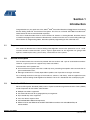
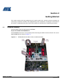
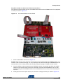
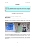
STK512 .................................................................................................................... AVR-based Uni-directional Radio Starter Kit Featuring Secure Rolling-Code RF Transmission Encryption User Guide Note: This Radio Starter Kit is not self-contained. It is based on an Atmel® AVR® STK®500 Flash Microcontroller Starter Kit that must be obtained separately. 5170C–AVR–10/09 Table of Contents Section 1 Introduction................................................................................................................. 1-1 1.1 Purpose.............................................................................................................................. 1-1 1.2 General Description ........................................................................................................... 1-1 1.3 Evaluation Kit Features...................................................................................................... 1-1 1.4 Included in the Kit .............................................................................................................. 1-2 Section 2 Getting Started ........................................................................................................... 2-1 2.1 Hardware Assembly........................................................................................................... 2-1 2.2 Initial Programming ............................................................................................................ 2-6 2.2.1 Programming the ATmega88 to Control the Receiver......................................... 2-6 2.2.2 Programming the Transmitter(s).......................................................................... 2-7 2.3 Teach the Transmitters to the Receiver............................................................................. 2-8 2.4 The Demonstration ............................................................................................................ 2-9 Section 3 Programming Notes ................................................................................................... 3-1 3.1 Configuration...................................................................................................................... 3-1 3.2 Project Compilation............................................................................................................ 3-2 3.3 EEPROM Image Generation.............................................................................................. 3-2 Section 4 Troubleshooting Guide ............................................................................................... 4-1 STK512 User Guide i 5170C–AVR–10/09 Section 1 Introduction Congratulations on your purchase of the Atmel® AVR®-based Uni-directional Radio Starter Kit featuring Secure Rolling Code RF Transmission Encryption. This kit uses an Atmel STK®500 Flash Microcontroller Starter Kit that must be obtained separately. This User’s Guide describes how to use this Starter Kit. Section 2, Getting Started, describes how to assemble and program the hardware to demonstrate a wireless link that uses a secure rolling code algorithm. Section 3, Programming Notes, describes optional programming for the advanced user. 1.1 Purpose This starter kit demonstrates a Secure Rolling Code Algorithm transmission protocol for use in a unidirectional wireless communication system. Typical applications for this algorithm are garage door openers, remote keyless entry, passive entry, and remote car-start systems. 1.2 General Description This kit demonstrates the transmission protocol with one receiver and a pair of associated transmitters. However, a typical system can support many more transmitters. Characteristics of this protocol are: A transmission-encryption value that is valid only once, preventing interception and re-transmission to gain unauthorized access, Message content that is virtually impossible to predict, even if previous messages are known. For a thorough technical coverage of the hardware, software, and theory, read the application note, “AVR411: Secure Rolling Code Algorithm for Wireless Link” that is included on the accompanying CD. 1.3 Evaluation Kit Features Advanced Encryption Standard (AES) and its Cipher-based Message Authentication Code (CMAC) mode of operation for transmitter authentication: Multiple transmitters supported PC command-line tools for cryptographic key management Up to 256-bit key sizes supported Less than 30 ms response time 315/434/868 MHz ISM-band frequencies ATA5771/73/74 and ATA8741/42/43 UHF ASK/FSK transmitters with embedded ATtiny44 microcontroller STK512 User Guide 1-1 5170C–AVR–10/09 Introduction 1.4 ATA5723/24/28 and ATA8203/04/05 UHF ASK/FSK receivers User-programmable transmitters with 6-pin ISP Sleep modes for minimal power consumption Included in the Kit Note: This Radio Starter Kit is not self-contained. It is based on an Atmel STK500 Flash Microcontroller Starter Kit that must be obtained separately. This starter kit includes all the essential components needed to demonstrate an AVR-based uni-directional radio that features a Secure Rolling-Code RF Transmission Encryption protocol. Contents of this kit are listed and shown in Figure 1-1. 1-2 5170C–AVR–10/09 Transmitter application board ISP programming adapter for Transmitter Receiver application board with external antenna STK512 Interface Board ATMega88 microcontroller (not shown) CDROM containing software, Data Sheets, and other documentation (not shown) STK512 User Guide Introduction Figure 1-1. Kit Contents For investigating further capabilities of this kit, the following are optional: JTAGICE mkII for debugging IAR Embedded Workbench® AVR C compiler for changing and recompiling the source code without porting it to another compiler (precompiled source code with default configuration is provided on the CDROM). STK512 User Guide 1-3 5170C–AVR–10/09 Section 2 Getting Started This section contains the steps required to get a simple system with a receiver and two transmitters up and running. Hardware assembly, initial programming of the components, teaching the transmitters to the receiver, and demonstrating the transmission protocol are described in the following subsections. 2.1 Hardware Assembly The kit hardware must be interfaced to the STK500. Step A: Assemble the STK500 Board The STK500 Board must be set up properly before mounting the STK512 Interface Board. The assembled STK500 Board is shown in Figure 2-1. Figure 2-1. STK512 User Guide STK500 Board with Ribbon Cables and Microcontroller 2-1 5170C–AVR–10/09 Getting Started 1. Carefully remove any ICs in the green “SCKT3200A2” socket. 2. Insert the furnished ATMega88 into the “SCKT3200A2” socket. Note: The orientation of the red stripe in the cable is not critical in the following steps as long as pin 1 is connected to pin 1. 3. Using a 6-pin jumper cable supplied with the STK500; connect the two male headers “ISP6PIN” and “SPROG2”. 4. Using a 10-pin jumper cable supplied with the STK500; connect the two male headers “PORTC” and “LEDS”. 5. Using a 10-pin jumper cable supplied with the STK500; connect the two male headers “PORTD” and “SWITCHES”. 6. Place jumpers on the following headers as shown in Figure 2-2. – VTARGET – AREF – RESET – XTAL1 – OSCEL (a 3-pin header. Place a jumper next to the “1” printed on the board). Figure 2-2. 2-2 5170C–AVR–10/09 Detail of Jumper Placement on the STK500 STK512 User Guide Getting Started Step B: Assemble and Attach the STK512 Interface Board The STK512 Interface Board must be assembled and mounted on the STK500 Board. The completed assembly is shown in Figure 2-3. Figure 2-3. Assembled STK512 Interface Board 1. Orient the STK500 as shown in the Figure 2-3. Caution: After the next step, whenever the interface board is removed from the STK500 sockets, use caution if a tool is used for leverage. It is easy to bend pins or otherwise damage the STK500 and/or the interface board. Use a rocking motion while steadily pulling (not prying) it straight from the sockets. 2. Insert the STK512 Interface Board into the EXPANDx sockets, oriented with the LEDs and red DIP switches to the left-hand side. To verify the orientation, check that the EXPAND0 pins on the Interface Board plug into the EXPAND0 socket on the STK500 Board. Press firmly so that the board pins seat well. 3. Install jumpers on all five pairs of pins (JP2, next to the “configure” button) as shown in Figure 2-4. STK512 User Guide 2-3 5170C–AVR–10/09 Getting Started Figure 2-4. 2-4 5170C–AVR–10/09 STK512 Jumper Placement STK512 User Guide Getting Started Step C: Mount the Receiver Application Board The Receiver Application Board must be mounted on the STK512 Interface Board. The completed assembly is shown in Figure 2-5. Figure 2-5. Completed Receiver Assembly Caution: After the next step, if the receiver board is removed from the interface board sockets, use EXTREME caution! The pins on the receiver board are very easily bent and broken! Use a rocking motion to lift the board straight (perpendicular) out of the socket. 1. Orient the receiver board above the Interface Board as shown in Figure 2-5. Carefully insert the Receiver Application Board into the STK512 Interface Board sockets. 2. Install the antenna onto the SMB connector. 3. Supply the STK500 with +12 V power by connecting it to a PC using the RS232 port. STK512 User Guide 2-5 5170C–AVR–10/09 Getting Started 2.2 Initial Programming After setting-up the hardware, insert the accompanying CD into the computer’s CDROM drive. Note: If you want to use something other than the pre-compiled demonstration software and EEPROM files included on the CD, there is additional programming information in Section 3, Programming Notes. 1. Apply power to the STK500 by moving the power switch toward the edge of the board. 2. If not already done, install and/or open AVR Studio. 3. When the first box appears entitled, “Welcome to AVR Studio 4,” click “Cancel” (to program the devices doesn't require that a “Project” be used). 4. Click on the black IC icon with “AVR” -- it is in one of the top rows of the AVR Studio screen. (Note: When hovering over this symbol with the mouse pointer, “connect to the selected AVR programmer” appears. This indicates that this is the correct icon). A pop-up window labeled “STK500” appears. 5. AVR Studio is now ready to program the transmitter(s) and receiver. 2.2.1 Programming the ATmega88 to Control the Receiver 1. Select the “Program” tab and then select ATmega88 from the pull down menu. 2. Select the “Advanced” tab and then select “read signature” to ensure that communication with the device is functioning properly. If the read attempt is successful, a number will show in the window. If not, a pop-up will appear describing the failure. Consult the STK500 documentation to handle any failures. 3. Select the “Fuses” tab and ensure that the Fuses are set as shown in Table 2-1 Table 2-1. Receiver ATmega88 Fuse Settings Fuse Name Boot Flash section size = 1024… Brown-out detection disabled Int RC Osc 8 MHz: … +64 ms Divide clock by 8 internally Watchdog Timer always on Setting Checked Checked Checked Not Checked Not checked 4. From the CD, in the folder “software\IAR\RX\Release\Exe,” program the flash of the ATMega88 with “RX_fffMHz.a90.” (Note: “fff” is 315, 434, 868 or 915, the frequency specified for this kit). 5. From the CD, in the folder “software\Precompiled,” program the EEPROM of the ATMega88 with “RX_EEPROM_AES128.hex.” The ATMega88 is now programmed to control the receiver. Note: 2-6 5170C–AVR–10/09 About receiver programming: the two rows of DIP switches on the interface board provide the capability to set the OPMODE and LIMIT registers of the receiver IC. These DIP switches are NOT used by this demonstration software, as the receiver is programmed by the ATmega88. More can be found about how these switches work by consulting the appropriate Data Sheets for the receiver ICs used in this kit. To avoid accidental misprogramming of the receiver IC when using this demonstration kit, avoid pushing the white “CONFIGURE” button when the black slide switch is in the “STK512” position! STK512 User Guide Getting Started 2.2.2 Programming the Transmitter(s) 1. On the STK500, remove the 6-pin cable from the “SPROG2” header, plug it into the ISP programming adapter. Next, insert the transmitter application board into the adapter, as shown in Figure 2-6. Figure 2-6. Transmitter Key Fob with 6-pin Cable 2. On the “Program” tab of the “STK500” pop-up window, select the ATtiny44 from the pull-down list. 3. In the “Advanced” tab select “read signature” to ensure that communication with the device is functioning properly. If the read attempt is successful, a number will show in the window. If not, a pop-up will appear, describing the failure. Consult the STK500 documentation to handle any failures. 4. Select the “fuses” tab and ensure that the Fuses are set as shown in Table 2-2. Table 2-2. Transmitter ATtiny44 Fuse Settings Fuse Name Preserve EEPROM memory… Brown-out detection disabled Int RC Osc 8 MHz: … +64 ms Divide clock by 8 internally Watchdog Timer always on Setting Checked Checked Checked Not Checked Not checked 5. From the CD, in the folder “software\IAR\TX\Release\Exe,” program the flash of the ATtiny45 with “TX.a90.” 6. From the CD, in the folder “software\Precompiled,” program the EEPROM of the Tiny45 with “TX_EEPROM_AES128_ID1.” 7. Repeat this process for the second transmitter, except with the file “TX_EEPROM_AES128_ID2.” The transmitters are now programmed and ready for use. STK512 User Guide 2-7 5170C–AVR–10/09 Getting Started 2.3 Teach the Transmitters to the Receiver In order for the rolling code to work, each transmitter must convey to (teach) the receiver three data elements: its unique serial number, its secret key, and its sequence counter value. The “learn mode” is physically activated at the receiver during which time authorized transmitters can transmit their specific information. This teaching and learning process is accomplished by the following steps. For security purposes, when the receiver enters the learn mode, all previous data concerning transmitters should be erased. This is discussed in further detail in section 3.2 of the “AVR411: Secure Rolling Code Algorithm for Wireless Link Application Note” that is furnished on the CDROM. This requirement has not been implemented in this starter kit in order to allow further investigation into this mode. Familiarize yourself with the following instructions before beginning the teaching process. Also, keep your transmitter key fobs readily available. The default timeout to teach a transmitter is 10 seconds before the receiver will exit the learn mode. 1. Enter learn mode on the receiver by pressing the SW5 button on the STK500. The LED marked LED5 illuminates, indicating that the receiver is in learn mode. 2. Within 10 seconds, press Switch 1 on the transmitter key fob you want the receiver to recognize. Inadvertently pressing any other button or combination of buttons will transmit an ordinary message that will be ignored by the receiver since the receiver is expecting a longer “teach” message. Once the receiver receives the “teach” message, the learn-mode LED5 blinks off once, and you have another 10 seconds to teach the next transmitter. If LED5 does not blink, the message was not received correctly, perhaps due to interference or an incorrect button combination. Repeat steps 1 and 2 until successful. Figure 2-7. 2-8 5170C–AVR–10/09 Transmitter Key Fob Button Numbering STK512 User Guide Getting Started 3. Repeat steps 1 and 2 for to teach additional transmitters. 4. When the last transmitter has been taught to the receiver, wait for the 10-second learn-mode timeout to expire. At this Point, LED5 goes off and the receiver is ready to accept regular messages from the transmitters. Note: 2.4 Whenever the maximum number of transmitters is reached, LED5 blinks to indicate that a transmitter has been learned, but there is not another 10-second delay. LED5 goes off immediately after blinking. The Demonstration On the STK500, LED0 through LED4 represent a sequential circular counter (i.e., LEDs 0 through 4 illuminate in sequence and then LEDs 0 through 4 again illuminate in sequence, etc.). Pressing Switch 3 on a learned transmitter key fob increments the code counter and the illuminated LED; pressing Switch 2, the counter and the illuminated LED de-increments. Since the rolling code is transparent (embedded in the transmitted message) to the end user of a system, by default, the software provided in this starter kit is designed to simply demonstrate the reliable receipt of transmissions originating from the transmitter key fobs. A necessary component of this secure encryption algorithm is synchronization between the transmitter and receiver. To demonstrate synchronization feature, a situation must be created to cause a transmitter key fob’s counter to become out of sequence with the receiver’s respective counter. With the source code provided, the window of acceptance defaults to a value of 100. That is, the transmitter key fob must increment its counter 100 times above the count the receiver remembers for that transmitter key fob. This can be done by moving the transmitter key fob out of range of the receiver and pressing either Switch 2 or 3 more than 100 times. When the transmitter key fob is again brought within range of the receiver; note that the receiver will not respond to that transmitter key fob because the counters are out of sequence more than 100. This synchronization feature is further explained in section 3.1.1 of the “AVR411: Secure Rolling Code Algorithm for Wireless Link Application Note” that is furnished on the CDROM. To simplify demonstrating the out-of-sync situation, the size of the “rolling window of acceptance” variable can be reduced. This reduces the number of times the transmitter key fob switches must be pressed to cause an out of sync condition. Similar to the above approach, incremented counter values can be changed through manipulation of the counter value variable directly in software. Atmel recommends appropriate variable monitoring capabilities be available before attempting this approach. Whichever approach is used, the transmitter key fob and receiver counter can be resynchronized by having the receiver relearn the transmitter key fob. STK512 User Guide 2-9 5170C–AVR–10/09 Section 3 Programming Notes The following describes optional programming that is not necessary to use the kit to demonstrate the rolling code algorithm over an RF link. In addition to the information below, the accompanying CD contains a “readme.html” file that documents user programming of both the receiver and transmitter. This information is included for the advanced user who wishes to experiment with the kit and its expanded capabilities. 3.1 Configuration There are numerous options for the system, e.g., cryptographic key sizes, message field sizes etc. The parameters are given as #define macros in the config.h files in both the transmitter and receiver source code folder. The most important parameters are given in. It is important that the parameters for the transmitter and receiver code are the same. The configuration file contains several other advanced parameters. Parameter usage is explained in comment blocks in the files themselves and should not be altered. Always keep a backup copy of the original default configuration. Table 3-1. Basic Configuration Parameters Parameter Name KEY_BITS Default Value 128 Description Size of the AES cipher key in bits. Allowed values are 128, 192 and 256 bits, where 256 bits is the most secure option. SERIAL_NO_BYTES 4 Size in bytes of the message field containing a transmitter's serial number. Allowed values are 1, 2, and 4 bytes(1). COMMAND_CODE_BYTES 1 Size in bytes of the message field containing the requested command. Allowed values are 1, 2, and 4 bytes(1). SEQ_COUNTER_BYTES 4 Size in byte of the message field containing the sequential counter value. Allowed values are 1, 2, and 4 bytes(1). MAC BYTES - 4 Size in bytes of the message field containing the MAC. The value must not be larger than 16 bytes. More bytes give a more secure authentication. MAX_TRANSMITTERS 5 Maximum number of transmitters that one receiver can learn. This number is limited by the amount of free EEPROM memory. A compile error will occur of the number is chosen too large. WINDOW SIZE Note: STK512 User Guide 100 The size of the rolling window of acceptance. 1. Serial number, command code and sequential counter value fields must not exceed 16 bytes. A compile error will occur if the total size exceeds this limit. 3-1 5170C–AVR–10/09 Programming Notes 3.2 Project Compilation This step can be skipped if you only want to use the precompiled source code with default settings. If not, compile projects for both the transmitter and the receiver. Detailed compilation instructions and fuse settings are giving in the source code documentation. 3.3 EEPROM Image Generation Allocate serial numbers and secret and shared keys for the system components. Then use the supplied command line tools to generate one HEX file for every unit. The secret key for the transmitters should be discarded after generating the HEX file. They are not needed and could compromise system security if they get into the wrong hands. Make sure that all transmitters that will be associated with a receiver have the same shared key as the receiver. Note: 3-2 5170C–AVR–10/09 1. The supplied tools are only meant for prototyping and evaluation. For full production use, a secure key management infrastructure should be established. STK512 User Guide Section 4 Troubleshooting Guide Table 4-1. Troubleshooting Solutions Problem LED on Receiver Application Board not active Reason Solution Power is not applied or is less than 5V Verify that 5V is supplied to the Receiver Application Board via on-board pins or through the STK512 Interface Board connection to the STK 500 (VTG jumper). DATA Selector switch was not set to the STK511 position when power was applied Set DATA Selector switch to STK511 and re-apply 5V supply Receiver in permanent sleep mode because Sleep mode of all 1s selected in OPMODE register Select different polling rate and re-program OPMODE register Receiver Application Board rotated 180° when mounted Verify that Receiver Application Board signal test points on the STK512 Interface Board are placed toward the DIP switches. Power not applied LED(s) on STK512 Corresponding DIP Switch bit(s) not set Interface Board not active Bias resistor(s) damaged Registers in the receiver do not appear to be programming Verify that Power is supplied to the STK512 Interface Board through either the Receiver Application Board or the STK500 Board (VTG jumper). Set the corresponding bit(s) to ON on the DIP Switch for that register. Replace the corresponding bias resistor(s) on the back of the STK512 Interface Board with 1 k Incorrect firmware loaded into the STK512 Interface Board where I/O port of the onboard microcontroller programmed to logic high Reload the STK512 Interface Board Firmware as described in Section 2.2. Power supplied is too low Verify that the power being supplied is 5V DATA Selector switch was not set to the STK511 position when Configure button pressed Set DATA Selector switch to STK512 and re-press button STK512 Interface Board firmware has become corrupted Reload the STK512 Interface Board Firmware as described in Section 2.2. Registers may be programming correctly with no visible Monitor the Data Test point with an oscilloscope to check signs of change Some external source may be holding for presence of the acknowledge bit. the Data line low Receiver Application Board rotated 180° when mounted Verify that Receiver Application Board signal test points on the STK512 Interface Board are toward the DIP switches. STK512 User Guide 4-1 5170C–AVR–10/09 Troubleshooting Guide Table 4-1. Troubleshooting Solutions (Continued) Problem Reason Solution STK512 Interface Board not correctly connected to STK500 Verify EXPANDO and EXPAND1 are properly oriented ISP ribbon cable not connected properly Unable to load STK512 Interface Board firmware Ensure ribbon cable connected between ISP6PIN header and SPROG3 header Check orientation of pin 1 on headers Incorrect device selected Select ATmega8515 from the Device menu. Verify that the signature byte matches in the Advanced tab Device present in STK500 sockets Remove all devices from the programming sockets of the STK500 ISP jumper not shorted on STK512 Interface Board Connect shunt Power and serial cable not connected to STK500 Verify setup of the STK500 hardware Battery dead Open Transmitter Application Board case and replace coin cell battery Demo Software corrupted Reload the desired software according to Section 2.2. Switch contact not made Ensure proper contact of the button to the Transmitter Application Board Low Battery voltage Replace coin cell battery Transmitter is in sleep mode Press button to wake from sleep mode Demo Software corrupted Reload the desired software according to Section 2.2. Transmitter Application Board Demo Software corrupted LED(s) constantly lit Reload the desired software according to Section 2.2. Transmitter not responding to button press No activity on Transmitter Application Board LED(s) Incorrect orientation of the ribbon cable connecting the Verify the orientation of both sides of the ribbon cable ISP header to the STK500 Unable to program Power not supplied to transmitter on-board Transmitter microcontroller Application board through ISP header Wrong device selected in the STK500 software Power and serial cable not connected to STK500 Supply 3 volts to the transmitter microcontroller through the coin cell battery or via the STK500 Select ATtinyl3 from the Device menu. Verify that the signature We matches in the Advanced tab Verify setup of the STK500 hardware Incorrect orientations of the Receiver Application Board Verify the hardware is assembled correctly as shown in or STK512 Interface Board Section 2. Power not properly supplied to all boards See the troubleshooting section for each board. Data Selector switch not set to STK500 position Set the switch to the proper position and re-run the demo Demo not working Microcontroller socket on STK500 not populated (STK500 LED(s) not responding to Corrupted software in the STK500 microcontroller transmitted signal) 4-2 5170C–AVR–10/09 The demo uses an ATmega88 microcontroller in the STK500 to decode the received signal Reload the Receiver Decode software as shown in Section 2. 10-pin ribbon cable not connected properly Verify that the 10-pin ribbon cable is properly connected to the LEDS header from the PORTC header on the STK500 Incompatible modulation used on the transmitter and receiver Verify that transmitter and receiver are both set for the same modulation type (ASK versus FSK) Receiver set to permanent sleep Check for Sleep bits in the OPMODE register set for all 1s Receiver limits incorrect Verify correct register settings as given in Section 2. Receiver antenna not connected Connect external whip antenna to Receiver Application Board STK512 User Guide Headquarters International Atmel Corporation 2325 Orchard Parkway San Jose, CA 95131 USA Tel: 1(408) 441-0311 Fax: 1(408) 487-2600 Atmel Asia Unit 1-5 & 16, 19/F BEA Tower, Millennium City 5 418 Kwun Tong Road Kwun Tong, Kowloon Hong Kong Tel: (852) 2245-6100 Fax: (852) 2722-1369 Atmel Europe Le Krebs 8, Rue Jean-Pierre Timbaud BP 309 78054 Saint-Quentin-enYvelines Cedex France Tel: (33) 1-30-60-70-00 Fax: (33) 1-30-60-71-11 Atmel Japan 9F, Tonetsu Shinkawa Bldg. 1-24-8 Shinkawa Chuo-ku, Tokyo 104-0033 Japan Tel: (81) 3-3523-3551 Fax: (81) 3-3523-7581 Technical Support [email protected] Sales Contact www.atmel.com/contacts Product Contact Web Site www.atmel.com Literature Requests www.atmel.com/literature Disclaimer: The information in this document is provided in connection with Atmel products. No license, express or implied, by estoppel or otherwise, to any intellectual property right is granted by this document or in connection with the sale of Atmel products. EXCEPT AS SET FORTH IN ATMEL’S TERMS AND CONDITIONS OF SALE LOCATED ON ATMEL’S WEB SITE, ATMEL ASSUMES NO LIABILITY WHATSOEVER AND DISCLAIMS ANY EXPRESS, IMPLIED OR STATUTORY WARRANTY RELATING TO ITS PRODUCTS INCLUDING, BUT NOT LIMITED TO, THE IMPLIED WARRANTY OF MERCHANTABILITY, FITNESS FOR A PARTICULAR PURPOSE, OR NON-INFRINGEMENT. IN NO EVENT SHALL ATMEL BE LIABLE FOR ANY DIRECT, INDIRECT, CONSEQUENTIAL, PUNITIVE, SPECIAL OR INCIDENTAL DAMAGES (INCLUDING, WITHOUT LIMITATION, DAMAGES FOR LOSS OF PROFITS, BUSINESS INTERRUPTION, OR LOSS OF INFORMATION) ARISING OUT OF THE USE OR INABILITY TO USE THIS DOCUMENT, EVEN IF ATMEL HAS BEEN ADVISED OF THE POSSIBILITY OF SUCH DAMAGES. Atmel makes no representations or warranties with respect to the accuracy or completeness of the contents of this document and reserves the right to make changes to specifications and product descriptions at any time without notice. Atmel does not make any commitment to update the information contained herein. Unless specifically provided otherwise, Atmel products are not suitable for, and shall not be used in, automotive applications. Atmel’s products are not intended, authorized, or warranted for use as components in applications intended to support or sustain life. © 2009 Atmel Corporation. All rights reserved. Atmel ®, logo and combinations thereof, AVR ®, AVR Studio ®, STK ® and others are registered trademarks or trademarks of Atmel Corporation or its subsidiaries. Other terms and product names may be trademarks of others. 5170C–AVR–10/09 /xM