1
Lab Course “Microcontroller Programming”
Exercise 1: Introduction and Digital I/O
As this is the first exercise sheet of the lab course, it provides a lot of informational prologue to
make your life with microcontrollers easier. Find the exercises for this session on page 15.
Overview on C Notation, Bit Manipulation and Operations
Throughout this lab course, we will program microcontrollers at a quite low level using the C
programming language. To be able to efficiently program the registers of the microcontroller, the
following sections will give you some useful hints.
Notation
In the following, we will use binary and hexadecimal numbers in the C language.
• To define a binary number, prepend it with 0b (e.g., 0b01010011 = 83).
• To define a hexadecimal number, prepend it with 0x (e.g., 0xFF = 0b11111111 = 255).
Individual bits of a register or variable are always numbered from right to left (e.g., 0 to 7 for an
8-bit number), which means that the “1” in the following binary number is located at position 1
(not 2): 0b00000010.
Bit Manipulation
When programming microcontrollers, a common task is to modify the values of individual bits of a
certain register or variable without changing the value of the other bits. Make sure you understand
why following bit manipulations yield the given results.
a) AND operator (&): The AND operator combines two bit patterns (numbers). The bits on
each position are combined individually. The result for a specific bit is 1 if both original bits
were 1.
Example: unsigned char x = 0b10110011 & 0b01101001, y = 60 & 13;
x is now 0b00100001, y is now 12.
b) OR operator (|): The OR operator combines two bit patterns (numbers). The bits on each
position are combined individually. The result for a specific bit is 1 if either of the original
bits was 1.
Example: unsigned char x = 0b10110011 | 0b01101001, y = 60 | 13;
x is now 0b11111011, y is now 61.
c) XOR operator (^): The XOR operator combines two bit patterns (numbers). The bits on
each position are combined individually. The result for a specific bit is 1 if exactly one of the
original bits was 1. The symbol to type is a circumflex.
Example: unsigned char x = 0b10110011 ^ 0b01101001, y = 60 ^ 13;
x is now 0b11011010, y is now 49.
d) One’s complement (~): The one’s complement negates each bit of a bit pattern (number)
individually. The symbol to type is a tilde (AltGr + +).
Example: unsigned char x = ~0b10110011, y = ~60;
x is now 0b01001100, y is now 195.
1/16
Lab Course “Microcontroller Programming”
e) Shift left (<<): The shift left operator shifts bits of a bit pattern to the left (most significant
bit), adding zero bits on the right and dropping excessive bits on the left. Mathematically,
if only zeros are dropped on the left, this corresponds to a multiplication by 2n , where n is
the number of times to shift.
Example: unsigned char x = 0b10110011, y = x << 3;
y is now 0b10011000.
f ) Shift right (>>): The shift right operator shifts bits of a bit pattern to the right (least
significant bit), adding zero bits on the left and dropping excessive bits on the right. Mathematically, this corresponds to a division by 2n and rounding the result down, where n is the
number of times to shift.
Example: unsigned char x = 0b10110011, y = x >> 3;
y is now 0b00010110.
All binary operators defined above also allow the assignment of the operation result to the first
operator. For this purpose, use the following notations: &=, |=, ^=, <<=, >>=.
Examples: a &= 0x02; b ^= 0b00000100; c <<= 3;
Bit Operations
A very common task is to modify individual bits. Here is how to do it in an efficient way.
a) Building bit masks: Many operations require a certain bit mask to be applied to a register
or variable. A bit mask can be built using many different techniques and the most efficient
way to do it depends on the operation to perform:
• Direct notation of bit masks: Bit masks may be directly notated in the source code.
This is the easiest, but also most obfuscated way, because there is no chance for the
reader to know why the bit mask has been built in this way and there is no easy way
to check its correctness. Hence, it should be avoided if possible.
Example: SPCR |= 0b01010000;
/* very hard to understand */
• Direct notation with bit shifting: Instead of directly notating each bit, the relevant
information can be presented by shifting ones into the respective bits. This makes
the whole expression a little bit more readable, because the bit position numbers are
encoded in the operation. The _BV() macro should be used in this case, which has
the following definition: #define _BV(bit) (1 << (bit)). Note that the result of the
shift is calculated by the compiler, so there is no runtime overhead involved.
Example: SPCR |= _BV(6) | _BV(4);
/* a little bit better */
• Naming of bit positions: The notation can be further improved if the bit positions
have individual names. This is true for most special purpose register bits.
Example: SPCR |= _BV(SPE) | _BV(MSTR);
/* even better */
Now it’s quite easy to find out that this command enables SPI in master mode (at
least if you know what the SPCR register is used for). This is why this notation is the
preferred notation. If you can’t use this notation for some reason, document the bit
mask by introducing a comment.
b) Setting individual bits: With the technique of bit masks, it’s now easy to set an individual
bit in a register or variable: just logically OR it with a bit mask with just that bit set to one.
Example: SPCR |= _BV(SPE);
/* enable SPI */
The above command actually evaluates to: SPCR = SPCR | 0b01000000;
2/16
Lab Course “Microcontroller Programming”
c) Clearing individual bits: Clearing a bit value is a little bit more complicated: we have to
AND the value with a bit mask set to all ones except the respective bit. This is achieved by
an additional one’s complement:
Example: SPCR &= ~_BV(SPE);
/* disable SPI */
The above command actually evaluates to: SPCR = SPCR & 0b10111111;
d) Toggling individual bits: Toggling of bits can be achieved with the XOR operator.
Example: SPCR ^= _BV(SPE);
/* toggle SPI */
The above command actually evaluates to: SPCR = SPCR ^ 0b01000000;
Overview on Version Control with Subversion
This lab course not only targets to teach you how to program microcontrollers, but also how
to manage your source code in a reasonable way. For this reason, we will use version control
mechanisms to manage the source code. Version control basically means that every incremental
change you make to your source code can be individually stored on a server. You can go back to
older versions of your source code and restored them if necessary. We are using the version control
system Subversion (short “SVN”) in combination with the TortoiseSVN client for this purpose.
The following sections will provide a quick overview over the features of Subversion and how to
use them from TortoiseSVN. If you are familiar with these concepts, you may skip this section.
Throughout the lab course, when we say “svn:”, we mean the path to your local working copy
root.
Advantages of Version Control
The naı̈ve approach to manage source code is to store it in a single directory and directly modify
it when it needs to be adapted. This approach has some fundamental drawbacks:
a) You source code is only stored at a single location. In case the hard disk drive fails, your
code will be lost.
b) If you make modifications to the code (e.g., remove an unused function) and realize later
that you actually needed the old code in a different context, you have to rewrite it. There is
no easy way to get the old code back.
c) If you are not the only one who modifies the code, you can quickly get inconsistencies between
multiple copies of the code that are hard to merge.
Of course you could create manual copies of your source code folder from time to time, name them
such that they remind you of which date the code belongs to, distribute copies to other computers
to avoid the single-point-of-failure scenario and talk very often with the other developers to avoide
merge conflicts. However, this is cumbersome and involves quite a lot of overhead.
Version control can help you to ensure safe storage of your code with the ability to go back to
older versions while making merging of changes between among developers (almost) an automatic
process. Let’s have a look at how this works.
Repository, Working Copy and Typical Operations
The basic workflow of Subversion is that when you begin to work, you first download an appropriate
portion of the required files from a server. These files are stored on the server in a so-called
3/16
Lab Course “Microcontroller Programming”
repository. The downloaded copy of the files is called working copy. The process of downloading files
from a repository to create a new working copyis called checking out the repository. A repository
can have an arbitrary amount of associated working copies. Typically every developer has a single
working copy, but it is also possible to have multiple of them.
After checkout, every developer works on the files locally (i.e., on their own hard disk drive). That
means that while working on the files, you will not need a connection to the server. Modifications
include editing of existing files, addition, deletion, renaming, copying and moving of files and
folders.
After you have applied and tested your changes, you might want to upload them to the server for
backup purposes and for being able to go back to this version of the files at a later point in time.
This will also make the changes available to other developers who work on the same files. The
process of uploading a set of changes to the server is called commiting the changes. Subversion
will only upload the files that have actually been modified.
As multiple members can work in parallel using this system, others might as well have committed
changes they have made to their local copies of the files. In order to obtain the most recent versions
of these files, you need to update your local repository from time to time. During this procedure,
the server will send you all files that have been modified on the server since your last update.
In case other developers modified the same files that you modified, Subversion might report during
commit that you have to update your working copy first. This is necessary to ensure that no
comflicting changes are committed to the server, since then the code on the server would probably
be broken. During the update, Subversion tries to resolve any pending merge conflicts. This is
possible as long as no two developers modified the same lines in the same files. Only if Subversion
is not able to automatically resolve a conflict you will have to manually resolve it.
Software Requirements
For using Subversion from Windows, the usage of the TortoiseSVN 1 client is recommended. It
integrates nicely into Windows Explorer and indicates the status of files (e.g., normal, modified,
added) by colored icon overlays. TortoiseSVN is preinstalled on the machines in the lab course
room.
Operations in TortoiseSVN
Checkout Within Windows Explorer, create a new, empty folder where you would like to store
the working copy. Right-click onto the folder name and choose SVN Checkout.... In the dialog,
specify the following URL of repository: https://svnknoll.informatik.tu-muenchen.de/mcp/
ws1112/gNN where NN corresponds to the two-digit number of your group (e.g., 01). Remove the
trailing gNN from the Checkout directory path. Leave the remaining settings intact and click OK.
Update Within Windows Explorer, right-click on your working copy folder and choose SVN
Update. This will download any updates from the server.
Commit Within Windows Explorer, right-click on your working copy folder and choose SVN
Commit.... In the dialog, enter a log message describing what you have done since the last update.
You might want to review the list of changed files in the area below the message text box. You
can inspect the individual changes by double-clicking on an item in that list. Remove the check
marks from the files that you do not want to upload to the server, if any. Then click OK.
1 http://tortoisesvn.net/
4/16
Lab Course “Microcontroller Programming”
Understanding icon overlays TortoiseSVN automatically highlights every file in a working copy
to reflect its current state. The following list explains the most important icon overlays:
Normal: the file or folder is under version control and has not been modified locally.
Modified: the file or folder is under version control and has been modified locally.
Ignored: the file or folder is not considered for version control (should not be uploaded).
Unversioned: the file is not yet under version control and also not ignored.
Added: the file or folder has been added to version control, but not yet committed.
Deleted: the file or folder has been removed from version control, but not yet committed.
Adding files to version control New files and folders must be manually added to version control
for Subversion to consider them. If you want to add a file or folder to version control, right-click
on it and choose SVN → Add.... Until committed, new files and folders will be marked with the
“plus” overlay (see above).
Removing files from version control If you accidentally added a file or folder that you do not
want to be under version control, right-click on the file or folder and select SVN → Delete (if the
file or folder has already been committed) or SVN → Undo Add... (if the file or folder has not
yet been committed). Until committed, deleted files and folders will be marked with the “cross”
overlay (see above).
Note that you can not 2 permanently delete a file from the repository – it can always be restored
at a later point in time. So be careful not to accidentally upload files with passwords or other
sensitive information in them.
Copying, moving and renaming files and folders Copying, moving and renaming files and folders
within a working copy requires some special attention. When you rename, copy or move a file or
folder directly within Windows Explorer, Subversion will not notice that the original item and the
new item are actually related. However, for being able to go back to older versions of the file at a
later point in time, Subversion will need this information.
Hence, you should never copy, move or rename a file directly using Windows Explorer commands
if the source and the destination is inside the same working copy. You should rather use the
appropriate SVN commands:
• Renaming a file or folder: Right-click onto the respective file or folder, choose TortoiseSVN
→ Rename... and enter the new name for the item.
• Copying a file or folder: Right-click onto the respective file or folder and drag it to its new
location. In the popup menu, choose SVN copy versioned item(s) here. This will only work
if the destination folder is already a working copy folder. If it is not yet, first add the folder
to version control (see above). You do not have to perform a commit in between.
• Moving a file or folder: Follow the same steps as indicated above, but select SVN move
versioned item(s) here from the popup menu.
• Renaming items during copy or move: Follow the same steps as indicated above, but select
the respective operation from the popup menu.
2 There
is a way to do this, but it requires recreation of the repository on the server!
5/16
Lab Course “Microcontroller Programming”
Preventing files from being version controlled Some files and folders should not be version
controlled. For example, compilation artifacts (object files, executables, etc.) should never be
version controlled, because they will change with every build and can be easily recreated by a
developer on demand. To prevent such files and folders from being accidentally committed, you
should add them to the ignore list. Ignored files and folders will be marked with the “ignored”
overlay (see above).
There are two types of ignore lists:
• The folder-based ignore list is a property that can be assigned a different value on each
folder in a working copy. It will then only affect items within that specific folder. To add
a file or folder to the folder-based ignore list, right-click on the respective item and choose
TortoiseSVN → Add to ignore list and choose a matching item. Remember that you need
to commit the change on the parent folder for it to become effective on other developer’s
working copies. To inspect the list of ignored files, right-click on the respective folder, choose
Properties and click the Properties... button on the Subversion tab. If an ignore pattern
has been defined for that folder, you should see an item of type svn:ignore that you can
edit manually from within that dialog. Again, do not forget to commit your changes on the
parent folder for them to become effective.
• The global ignore list is specific to a user account on the computer and specifies files and
folders that should be ignored in any working copy on that computer. You can see and edit
it from the TortoiseSVN settings dialog: right-click in Windows Explorer, TortoiseSVN →
Settings → General → Global ignore pattern.
Looking up the history of changes Subversion retains a history of all changes to the files at
the granularity of commits to the server. To take a look at all changes, right-click on a working
copy folder for which you would like to see the changes and choose TortoiseSVN → Show log. The
dialog shows a list of revisions (individual committs) at the top. When you select a revision, you
can inspect the associated log message (in the middle) and the list of affected files (at the bottom).
More Information about Subversion and TortoiseSVN
If you need more information about version control, the following references are recommended:
• TortoiseSVN: TortoiseSVN – A Subversion client for Windows (user manual), available online at http://tortoisesvn.net/docs/release/TortoiseSVN_en/ or by right-clicking on
a folder in Windows Explorer and choosing TortoiseSVN → Help (if TortoiseSVN is installed).
• Subversion: Version Control with Subversion (e-book), available online at http://svnbook.
red-bean.com/
Microcontrollers
Overview of Microcontrollers
Over the last decades, microcontrollers became ubiquitous in everyday life. Microcontrollers play
a key role in performing control and signal processing tasks. Applications range from from small
consumer electronic products like MP3 players and digital cameras over industrial products like
cars and aircrafts to power plants. In contrast to microprocessors used in standard PCs and servers,
microcontrollers are designed for dedicated applications. Special-purpose computer systems constructed with microcontrollers are also known as embedded systems.
6/16
Lab Course “Microcontroller Programming”
Basic Elements of a Microcontroller
A microcontroller is more than just a Central Processing Unit (CPU). It is typically a CPU
integrated with memory and many other peripherals. This integration drastically reduces the
number of chips and the amount of pins and wirings required on a printed circuit board and thus
reduces the cost. Hence, the term Microcontroller Unit (MCU) is also commonly used. MCUs have
proven to be highly popular in embedded control systems since their introduction in the 1970s.
MCUs commonly incorporate the following features:
• CPU (typically 8-bit to 32-bit).
• Clock generator, often a crystal or real-time clock (RC) oscillator.
• ROM, EEPROM and flash memory for program and configuration storage.
• RAM for temporary data storage.
• General purpose input/output pins, configurable by software.
• Timers and Pulse Width Modulation (PWM) generators.
• Communication ports like Universal Asynchronous Receiver/Transmitter (UART), Universal
Serial Bus (USB), Controller Area Network (CAN), etc.
• Analog-Digital Converters (ADC) and Digital-Analog Converters (DAC).
• In-System Programming (ISP) and debugging facilities (e.g., JTAG port).
Since the MCU offers flash memory, we can put the whole program into the controller itself. The
program will stay there until being overwritten by a different program, even if system power is
disconnected. The memory is similar to the one found in USB sticks or memory cards.
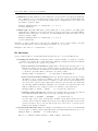
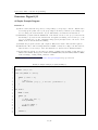
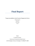
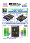
Figure 1 shows a diagram of the ATmega168 microcontroller, which we will use in this lab course.
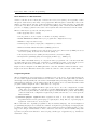
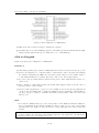
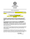
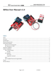
Figure 2 shows the AVR CPU architecture, which is common to all controllers of that family.
Programming Model
The programming model represents the programmer’s view of the device. It typically includes the
set of accessible registers and the instruction set. In microcontrollers, each register has a predefined
and unique address (usually associated with a meaningful name). Reading/writing to this address
will result in accessing the corresponding register. Most registers can be very much used like normal
program variables. Registers can be divided into two categories:
a) Special purpose registers: These registers are used to store the configuration or status
of the device. For example, the 8-bit microcontroller ATmega168 has a register called CKSEL
(clock selection) that allows to define the frequency at which the MUC operates. The meaning
of the bit fields in the configuration registers is predefined and needs to be looked up in the
MCU’s manual.
b) General purpose registers: These registers are used to store temporary values. ATmega168 includes 32 8-bit general purpose registers (R0 to R31). The set of general purpose
registers is often referred to as register file.
Microcontrollers were originally programmed only in assembly language, but various high-level
programming languages are nowadays also available. Compilers for general purpose languages (like
C, which we will be using) will typically have some restrictions as well as enhancements to better
support the unique characteristics of microcontrollers. Some microcontroller families ship with
special development environments to aid developing certain types of applications (e.g., AVRStudio
in this lab course).
7/16
Lab Course “Microcontroller Programming”
Figure 1: ATmega168 block diagram
Figure 2: AVR CPU architecture
8/16
Lab Course “Microcontroller Programming”
Input and Output
Input and output can either be digital or analog.
• Digital inputs: A typical application for a digital input is attaching a switch or another
digital sensor to it. Whether the value on the pin is considered 0 or 1 depends on the input
voltage at that pin. Since our microcontroller operates at 5 V, values higher than 3 V are
considered as “high”.
• Digital outputs: Digital outputs can be directly attached to LEDs (Light Emitting Diodes,
an energy-saving and long-living replacement for a small lamp) and indirectly to stepper motors, electromagnetic valves, relays and many other components. Note that directly attaching
some of these components to the microcontroller might destroy the controller, because the
current flow might be too high. If devices that drain a lot of current should be operated by
a microcontroller, driver circuits (e.g., transistors) have to be added in addition.
• Analog inputs: Analog voltage values at a certain physical pin are converted into a digital representation by the microcontroller’s ADCs. Typical applications are potentiometers,
temperature sensors or light sensors.
• Analog outputs: Some microcontrollers also support generation of different voltages. A
digital representation of the voltage to generate is then input into a DAC. The result can be
used to drive components that support a range of operation voltage. A simple example would
be an LED that should be driven at different levels of brightness. However, we will later see
that using DACs is not the only way to achieve this. The same restrictions for current flow
mentioned above also apply to analog outputs.
Digital interfaces can also be used for communication with other devices by physically connecting
the two devices and implementing a common protocol on the I/O lines. Typical examples are
RS232, SPI, I2 C or CAN. We will cover this topic in subsequent lab course exercises.
Firmware
Microcontrollers are usually used to perform predefined tasks in a periodic manner. In this case,
the program running on a microcontroller is commonly called firmware, representing a feature that
it is somehow fixed. There is no strict or well defined boundary between firmware and software,
both are quite loose descriptive terms. However, firmware is typically involved with very basic
low-level operations in a device, without which the device would be completely non-functional.
Because of its periodical behavior, the firmware is usually implemented as an endless loop:
1
2
3
i n t main ( ) {
/∗ I n i t i a l i z e t h e system ∗/
do init ();
4
while ( 1 ) {
/∗ The p e r i o d i c t a s k ∗/
do my task ( ) ;
}
5
6
7
8
9
/∗ I f we g e t here , t h e d e v i c e w i l l h a l t u n t i l b e i n g r e s e t : −(
∗/
/∗ We u s u a l l y do not want t h i s t o happen , hence t h e w h i l e l o o p . ∗/
return 0 ;
10
11
12
13
}
9/16
Lab Course “Microcontroller Programming”
The ATmega168 Microcontroller
We will use the ATmega168 microcontroller in this lab course. It is an 8-bit controller, i.e., 8
bits are being processed per execution cycle. The controller can be driven at up to 20 MHz. The
program memory is 16 KB large and it has 1 KB SRAM for variables and 512 bytes EEPROM
for configuration storage. Furthermore, it offers 3 I/O interface ports, each consisting of multiple
physical pins.
Ports
The 3 available ports of ATmega168 are named port ’B’, ’C’ and ’D’. The reason why ’A’ is left
out is that other devices from the AVR family support more ports with different functionality and
to keep the naming consistent across all devices, the identifier ’A’ is not used here.
Each port has up to 8 pins. A pin is a physical (digital or analog) input or output of the microcontroller.
Now let’s see an example. We would like to programmatically retrieve the value of the pins of port
’B’ of ATmega168, an 8-bit general purpose I/O port. First, we need to know the address of the
respective register. This value is of course defined in a header file named <avr/io.h>, which we
will include later on.
For reference, here is what is defined in that header file for port ’B’:
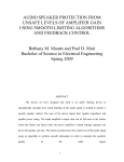
1
2
3
#define PINB ( 0 x03 )
#define DDRB ( 0 x04 )
#define PORTB ( 0 x05 )
/∗ Port Input Pin R e g i s t e r ∗/
/∗ Data D i r e c t i o n R e g i s t e r ∗/
/∗ Data R e g i s t e r ( Output ) ∗/
Each 8-bit general purpose I/O port has three registers associated to it: the PINx, the DDRx and
the PORTx register, where x is to be replaced by the respective uppercase letter of the port.
a) Data Direction Register: The DDRx registers define which pins of a port should be used
as an output and which should be used as an input. This can be defined individually for each
pin. A zero at the respective bit location means that the pin is an input, a one means that
it is an output pin. When powering the device on, the DDR registers are set to 0x00, which
means that all pins are inputs by default.
Example: DDRB = 0b01101000;
Pins 0, 1, 2, 4 and 7 of port ’B’ are defined as inputs, pins 3, 6 and 7 as outputs.
According to the above lecture on bit manipulation, a better way to write this would be:
DDRB = _BV(DDB7) | _BV(DDB6) | _BV(DDB3);
b) Data Register (Output): The PORTx registers define which physical pins should be high
(5 V) when the respective pin is defined as an output according to DDRx.
Example: DDRB = 0b11111111; PORTB = 0b00001111;
All pins of port ’B’ are defined as outputs, the first four ones are at a level of 5 V, the other
ones are at a level of 0 V.
If a pin has been defined as an input, the PORTx registers are used to switch on so-called
pull-up resistors. They are used to discharge parasitic induction that appears, because the
“open” (non-connected) pins of the controller act as an antenna. The pull-up resistors allow
for the input signal to be at a clearly defined level. However the pull-up resistors’ resistance
is high enough to allow an external circuit to drive the pins to the respective value if needed,
so there is in general no need to switch the pull-up resistors off. Note that as the name
suggests, the pull-up resistors pull the level of a pin to ’high’ (5 V) if the pin is not driven
10/16
Lab Course “Microcontroller Programming”
low by the circuit attached to the physical pin. This means that the respective pins will read
as ’1’.
c) Port Input Pin Register: The PINx registers allow to read the current status of the pins
regardless of how the respective pins are currently configured.
Example: DDRB = 0b00000000; unsigned char b = PINB;
This example defines all pins of port ’B’ to be inputs and then stores the current value at
the pins in the variable b.
For a more in-depth description of these registers, please refer to the ATmega168 manual3 .
With this definition, a simple (albeit not very meaningful) program could look like this:
1
2
/∗ Make a l l p i n s o f p o r t ’B ’ o u t p u t s ∗/
DDRB = 0xFF ;
3
4
5
/∗ Make a l l p i n s o f p o r t ’C ’ i n p u t s ∗/
DDRC = 0 x00 ;
6
7
8
/∗ Wait f o r p i n 1 on p o r t ’C ’ t o become ’ h i g h ’ ∗/
while ( 0 == (PINC & BV(PC1 ) ) ) ;
9
10
11
/∗ S e t t h e v a l u e o f p i n 2 on p o r t ’B ’ t o ’ h i g h ’ ∗/
PORTB |= BV(PB2 ) ;
Development Board and IDE
STK500 Development Board
ATmega168 is a low-power 8-bit microcontroller developed by Atmel4 . For the key features of this
product, see the first page of the manual5 .
For easy interaction with the microcontroller, we are using the STK500 6 development board,
which allows us to directly access all relevant signals of the microcontroller. The development
board features the following components:
• A socket for the microcontroller (already mounted).
• Connectors for all general purpose input/output (I/O) pins of the microcontroller.
• Serial interfaces for communication with the host PC.
• 8 LEDs for visualizing the current state of the microcontroller.
• 8 push-buttons (switches) for interacting with the program on the microcontroller.
Important note: STK500 only supports 6 of the 8 LEDs on the board if used with ATmega168
and LEDs are connected to port ’B’. LED6 and LED7 will not work in this configuration!7
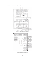
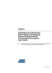
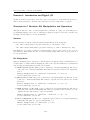
Please make sure that the following cable connections are set up on the development board (see
also figure 3). This is the initial configuration for all subsequent lab course exercises.
3
4
5
6
7
svn:/generic/atmega168.pdf, http://atmel.com/dyn/resources/prod_documents/doc2545.pdf
http://www.atmel.com/
svn:/generic/atmega168.pdf, http://atmel.com/dyn/resources/prod_documents/doc2545.pdf
svn:/generic/stk500.pdf, http://atmel.com/dyn/resources/prod_documents/doc1925.pdf
To be precise, PB6 and PB7 are not connected to the PORTB header on the STK500 board. The reason for this is
that an alternative function of these pins is to attach an external clock and STK500 rather uses these pins for
that purpose.
11/16
Lab Course “Microcontroller Programming”
Figure 3: Initial Setup of STK500 Development Board
• Programming: Connect the primary serial interface of the PC (COM1) to the RS232 CTRL
interface of the board.
• Use the six-wire pin to connect the ISP6PIN header to SPROG2 (be sure to connect pin 1 on
one connector to the respective pin 1 on the other connector).
• LEDs: Connect PORTB to LEDS using a ten-wire cable.
• Switches: Connect PORTC to SWITCHES using another ten-wire cable.
• Power supply: Connect the power supply to the respective connector on the board.
AVRStudio IDE
AVRStudio is a Integrated Development Environment (IDE) provided by Atmel for writing and
debugging applications. AVRStudio itself is not shipped with a tool chain for ATmega168 (compiler, assembler, linker, etc.), rather, it relies on external packages to provide those tools to compile
a C program. In our case, we use WinAVR, which is a free GCC based tool set.
Setting up an AVRStudio Project
1. Run AVRStudio by selecting Atmel AVR Tools → AVR Studio 4 in the start menu. You
might want to copy the shortcut to your desktop. Create a new AVR-GCC project.
2. Let AVRStudio create the project directory for you, but without an initial file.
3. Choose AVR Simulator as Debug Platform and ATmega168 as Device.
4. Adapt the project settings (right click on the project name, Edit Configuration Options...):
• General → Frequency: 16000000 Hz
• General → Optimization: -Os
12/16
Lab Course “Microcontroller Programming”
• Custom Options → External Tools: Make sure the Use WinAVR checkbox is checked.
5. Copy your source and header files to the directory you just created (or write them).
6. Use drag & drop from Windows Explorer to add the source and header files in the project
directory to the project.
Uploading a Program to the Target
1. In the menu, select Tools → Program AVR → Connect. . . . Select STK500 and the COM
port the device is attached to (usually COM1 or COM2). If you can’t find the correct port, use
the Windows Device Manager or a program like HyperTerminal to enumerate all available
ports.
2. In the Main tab, select the correct device ATmega168 as well as ISP mode. ISP Frequency
can be set to 1.843 MHz (maximum value for faster programming).
3. Choose the compiled Input HEX file at the Flash area under the Program tab. You can use
the . . . button to select the file on disk. When building a project from within WinAVR, the
*.hex file should be located in the default subdirectory of your project. Click the Program
button to upload it to the controller.
Warning: Do not modify the settings in the other tabs, especially not the Fuses or LockBits.
You could irrevocably lock the microcontroller so that it can not be programmed any more!
13/16
Lab Course “Microcontroller Programming”
Exercises start on the next page
14/16
Lab Course “Microcontroller Programming”
Exercises: Digital I/O
A Simple Example Program
Exercise 1.1
a) Check out the Subversion repository corresponding to your group8 to drive Z:. Ask the tutor
for setting up the password for your group. Inspect the files you find in your working copy.
Do not change the folder structure, as you will submit your solutions via Subversion.
b) Familiarize yourself with the AVRStudio environment. Create a new project and add the
file blinky.c (located in svn:/exercise01 and printed in listing 1 for reference) to your
project. Compile the code into a firmware image (*.hex) and upload it to the device. Some
LEDs on the board should start blinking.
c) Analyze the program you have just compiled. Why is the avr/io.h header file required?
d) What is the effect of the following instruction? DDRB = 0x2A; According to the introduction,
what would be a better way to write the instruction so that it is more human-readable?
e) In the function wait(), we used the type int32_t. What is the meaning of this data type?
Which other similar data types are defined in <WinAVRPath>\avr\include\stdint.h? What
is the advantage of using int32_t instead of int?
8 URL:
https://svnknoll.informatik.tu-muenchen.de/mcp/ws1112/gNN with group number NN
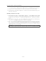
Listing 1: Simple example program (blinky.c)
1
/∗ R e q u i r e s LEDs t o be c o n n e c t e d t o PORTB ∗/
2
3
#include <avr / i o . h>
4
5
6
7
8
9
10
11
12
void w a i t ( i n t 3 2 t c o u n t e r )
{
while ( c o u n t e r > 0 )
{
c o u n t e r −−;
asm v o l a t i l e ( ”nop ” ) ; /∗ Prevent o p t i m i z a t i o n ∗/
}
}
13
14
15
16
i n t main ( )
{
DDRB = 0x2A ;
17
while ( 1 )
{
/∗ Wait some time ∗/
w a i t ( 0 x8FFFF ) ;
18
19
20
21
22
/∗ Toggle LEDs ∗/
PORTB ˆ= 0x2A ;
23
24
}
25
26
return 0 ;
27
28
}
15/16
Lab Course “Microcontroller Programming”
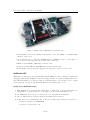
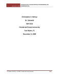
Figure 4: Pin Configuration of ATmega168
f ) Why is the asm volatile ("nop"); instruction required?
g) On which factors does the blinking frequency of the LED depend? In which situations might
using a wait() function like the one defined above be of disadvantage?
GPIO on ATmega168
Figure 4 shows the pin configuration of ATmega168.
Exercise 1.2
a) How many general purpose pins does ATmega168 have and how are they associated to ports?
b) Develop an application to count the number of times that a button is pressed and display
the current count using the LEDs. For each button press, switch one more LED on (up to
6, since PB6 and PB7 are not usable). Reset the count to zero if it is larger than 6.
c) Do you see any problems with the current button press counter implementation? How “accurate” is it?
d) Try to handle a continuously pressed button (like what happens when you press a key on
the keyboard for a few seconds).
e) Develop a fancy application to toggle one or more LEDs on/off. Use at least two push-buttons
on the board. You might want to make the blinking frequency adjustable, switch LEDs on
an off by a press of a button, or similar. Document your program so that it becomes clear
what it does.
Hints
• Note that the LED/switch logic of the development board’s LEDs and switches might not
meet your assumptions. To light up an LED, you have to write a zero to the corresponding
pin. The same logic applies to the buttons; the corresponding pin is low when a button is
pressed.
Remember: Save each of the solutions to the exercises in this lab course as a separate AVRStudio
project and commit your solutions together with the answers to the questions to the Subversion
repository! Do not forget to document your code!
16/16