1
[INTRODUCTION TO MICROCONTROLLER PROGRAMMING AND
December 4, 2009 COMMUNICATION]
Christopher S. McCoy
Dr. Zalewski
CEN 3213
Florida Gulf Coast University
Fort Myers, FL
December 4, 2009
Christopher S McCoy Fall 2009 Florida Gulf Coast University
Page 1
[INTRODUCTION TO MICROCONTROLLER PROGRAMMING AND
December 4, 2009 COMMUNICATION]
Section 1: Introduction
Overview
This project will provide an overview, including sample work, of the interaction between a user, an
Atmel AVR STK500 (P/N#ATSTK500) microcontroller, external temperature sensor and LED display.
Included will be a short introduction and overview of the integrated development environment (IDE)
that Atmel packages with the microcontroller card as well some sample diagnostic applications used to
test the overall functionality of the controller. This project will serve as a step-by-step manual so that
any user will be able to follow page by page and recreate the work I have outlined.
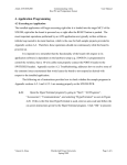
Problem Introduction
The goal of this project is to compile a detailed and easy to follow tutorial detailing the setup and
implementation of an Amtel AVR STK500 microcontroller board, temperature sensor and LED display.
This will be accomplished though a detailed set of step by step instruction including illustrations and
labeled photos showing the correct setup. A section outlining the setup and use of the Atmel IDE and
any other required testing applications. Another section will outline the application development and
implementation. It will include pseudo code as well as sample sections from the actual program.
Christopher S McCoy Fall 2009 Florida Gulf Coast University
Page 2
[INTRODUCTION TO MICROCONTROLLER PROGRAMMING AND
December 4, 2009 COMMUNICATION]
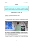
Required Materials and Component Illustrations
-Atmel AVR STK500 Starter Kit (P/N#ATSTK500)
-Personal Windows Based Computer
-If using Windows Vista you will need to download HyperTerminal. See section 4 for more information.
-10-15 V AC/DC power supply with 500mA minimum
- mwTWI Temperature sensor – available from: http://shop.myavr.de/AddOns%20und%20Module/myTWI%20Add-On%20Temperatursensor.htm?sp=article.sp.php&artID=71
- Metal Gear 1.5-3VDC Motor: RadioShack 273-058
http://www.radioshack.com/product/index.jsp?productId=2102828
-Atmel AVR Studio 4.16 (or later) IDE Windows based development tool (other operating system
compatible IDE’s are available for download from various websites but will not be covered in this guide)
-Minimum System Requirements are as follows:
-486 Processor (Pentium recommended)
-16MB of RAM
-15MB of HDD space
-Windows 95/98/2000 or NT 4.0
-115200 baud RS232 Port
-Test System One Specifications:
-Intel Core2 Quad CPU Q6600 2.40GHz
-8GB Corsair DDR2 800MHz RAM
-500GB Western Digital HDD model WD5000AACS
-Windows Vista Ultimate 64
-Dynex DX-UBDB9 USB to RS2323 serial port adapter cable with corresponding device driver
-Test System Two Specifications:
-Intel Core2Duo Model T7250 2.00GHz
-3.0GB of DDR2 RAM
-150GB Fujitsu HDD Model MHY2160BH
- Dynex DX-UBDB9USB to RS2323 serial port adapter cable with corresponding device driver
Note: All testing and development will be done on a Windows Vista, both 32 bit and 64 bit, based
machine. Compatibility with Windows XP will also be tested
Christopher S McCoy Fall 2009 Florida Gulf Coast University
Page 3
[INTRODUCTION TO MICROCONTROLLER PROGRAMMING AND
December 4, 2009 COMMUNICATION]
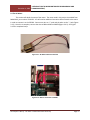
Figure 1.1: 6-wire, 10-wire and 2 wire cables.
Figure 1.2: RSR232 serial cable and Dynex RS232 to USB adapter cable.
Figure 1.2: Power adapter (used) and the adapter wire provided with kit (not used)
Christopher S McCoy Fall 2009 Florida Gulf Coast University
Page 4
[INTRODUCTION TO MICROCONTROLLER PROGRAMMING AND
December 4, 2009 COMMUNICATION]
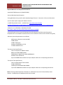
User Interface
Target Socket
Control
Figure 1.3: Section diagram of the STK500
The STK500 is composed of 3 sections as illustrated above. The target section contains the
plastic dual in-line sockets, programming headers and the jumpers used in board configuration. The
control section provides an interface for the host PC and the MCU to communicate. The user interface
section contains the LED’s, push button switches and input/output headers.
Christopher S McCoy Fall 2009 Florida Gulf Coast University
Page 5
[INTRODUCTION TO MICROCONTROLLER PROGRAMMING AND
December 4, 2009 COMMUNICATION]
Figure 1.4: STK500 Components [1]
Figure 1.5: ATMEGA8515L-8PU preinstalled at SCKT3000D3.
This is an 8-bit RISC MCU in PDIP form.
All 6-pin headers in the target socket section are color and number coordinated with their
respective target headers. Once the ISP and its target are connected this also allows all other sockets to
Christopher S McCoy Fall 2009 Florida Gulf Coast University
Page 6
[INTRODUCTION TO MICROCONTROLLER PROGRAMMING AND
December 4, 2009 COMMUNICATION]
be programmed that are bordered in the same color. You can seem some examples of this above and
later on in section 2 when the hardware connectivity is explained.
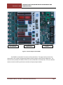
As stated above the user interface section contains the push-buttons, LED’s and the I/O ports
used to activate the LED’s or notify the MCU of a button press. There are 8 programmable buttons as
well as 8 corresponding LED’s.
Figure 1.6: Buttons 5, 6 and 7 as well as the switch header.
Figure 1.7: Switch 1, 1 and 2 and the LED control header.
Christopher S McCoy Fall 2009 Florida Gulf Coast University
Page 7
[INTRODUCTION TO MICROCONTROLLER PROGRAMMING AND
December 4, 2009 COMMUNICATION]
The mwTWI Temperature sensor used is a pressed circuit board containing an LM75
temperature sensor [3]. Serial data and serial clock lines are the most important lines used in
communication with the main MCU[3].
1
2
3
Figure 1.8: 1) SDA line, 2) SCL line, 3) LM75 Temperature Sensor.
Christopher S McCoy Fall 2009 Florida Gulf Coast University
Page 8
[INTRODUCTION TO MICROCONTROLLER PROGRAMMING AND
December 4, 2009 COMMUNICATION]
Section 2: Problem introduction
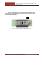
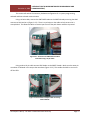
2.1 Initial Setup
The microcontroller board must first be setup to accept programming. To achieve this we must
take the 6-pin ISP cable (figure 2.1.3) and connect it from ISP6PIN to SPROG3 (figure 2.1.2). Next
connect the USB to Serial adapter into the main (middle port; figure 2.1.2) serial port. Then connect the
USB cable into an available port on the host PC. Lastly connect the approved AC/DC power adapter into
the power connector located on the microcontroller (figure 2.1.1).
Figure 2.1.1: From top to bottom: power light, power switch, power adaptor port.
The upper left also contains the reset button.
Christopher S McCoy Fall 2009 Florida Gulf Coast University
Page 9
[INTRODUCTION TO MICROCONTROLLER PROGRAMMING AND
December 4, 2009 COMMUNICATION]
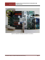
Figure 2.1.2: The above images show the location for the ISP6PIN cable and the
correct RS232 port to be used for programming.
Figure 2.1.3: Sample image of the proper RS232 connection from STK500 to host pc, the
6 pin ISP cable connecting the ISP6PIN to SPROG3, and the power adaptor location.
2.2 Port Setup for Data Transmission
Christopher S McCoy Fall 2009 Florida Gulf Coast University
Page 10
[INTRODUCTION TO MICROCONTROLLER PROGRAMMING AND
December 4, 2009 COMMUNICATION]
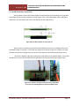
Disconnect the power adaptor and serial cable, if connected, before doing any of the following
steps. The alternate serial port (closest to the edge on the board; figure 2.1.2) is not configured by
default to allow the microcontroller to send data to the host PC. To enable this functionality take one of
the 2-wire cables and connect it from RXD and TXD pins to the PD0 and PD1 of PORTD (figure 2.2.1).
Please refer to the pg 64 in the ATmega8515 datasheet (see citation for availability) for detailed
description as the user manual does not detail this process.
Figure 2.2.1: Connect the 2 pin cable from the RXD/TXD connection to
PD0/PD1 making sure that the green wire connects RXD to PD0.
2.3 Conectivity Configuration
Christopher S McCoy Fall 2009 Florida Gulf Coast University
Page 11
[INTRODUCTION TO MICROCONTROLLER PROGRAMMING AND
December 4, 2009 COMMUNICATION]
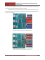
This section will outline the necessary hardware configuration for in-system programming,
onboard and host to board communication.
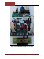
Using a 10 wire cable, connect the SWITCHES header to the PORTA headerp ensuring that PA0
connects to SW1 and so on (Figure 2.3.1). There is a red stripe on the cables to help ensure this is
accomplished. This allows the MCU to receive input if one of the push button switches is pressed.
Figure 2.3.1: Illustration for SWITCHES to PORTA
connection using a 10 pin cable.
Using another 10 pin cable connect LEDS header to the PORTC header. Make sure the same pin
correlation is followed in this step as the one above (Figure 2.3.2). This enables the MCU to turn on or
off the LED’s.
Figure 2.3.2: Illustration of 10pin cable connecting
LEDS to PORTC.
Christopher S McCoy Fall 2009 Florida Gulf Coast University
Page 12
[INTRODUCTION TO MICROCONTROLLER PROGRAMMING AND
December 4, 2009 COMMUNICATION]
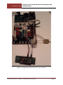
Figure 2.3.3: STK500 after completing steps outlined in 2.1, 2.2 and 2.3.
Christopher S McCoy Fall 2009 Florida Gulf Coast University
Page 13
[INTRODUCTION TO MICROCONTROLLER PROGRAMMING AND
December 4, 2009 COMMUNICATION]
2.4 myTWI Temperature Sensor Setup
Start by taking a 2-wire cable (red and black in the illustration) and connecting it to the ground
and voltage (5V) pins on the temperature sensor (Figure 2.4.1). Next take another 2-wire cable (blue
and white in the illustration) and connect the SDA and SCL pins (Figure 2.4.1).
Figure 2.4.0: myTWI Temperature sensor pin out.
Take the cable connected to ground/5V (red and black) and connect it to GRN and VTE pins of
the PORTE header on the MCU. Ensure that the red wire connects the 5V pin to the VTW pin and that
the black wire connects the ground on the sensor to the ground on the PORTE header (Figure 2.4.2).
Connect the SDA/SCL cable (blue and white) to PE0 and PE1 on the PORTE header. Ensure that
the blue wire connects SDA and PE0 while the white wire connects SCL and PE1 pins (Figure 2.4.2).
Figure 2.4.1 and 2.4.2: Two-wire connection to the temperature
sensor and corresponding MCU connection on PORTE header.
Christopher S McCoy Fall 2009 Florida Gulf Coast University
Page 14
[INTRODUCTION TO MICROCONTROLLER PROGRAMMING AND
December 4, 2009 COMMUNICATION]
Figure 2.3.3: Complete MCU following steps listed in 2.1, 2.2, 2.3 and 2.4.
Christopher S McCoy Fall 2009 Florida Gulf Coast University
Page 15
[INTRODUCTION TO MICROCONTROLLER PROGRAMMING AND
December 4, 2009 COMMUNICATION]
2.5 The DC Motor
This section will detail the setup of the motor. The motor used in this project is available from
RadioShack, part number 273-0258. You will need an additional two-wire cable to attach to the motor
in order to connect it to the STK500. Connect one wire to “+” pole and the other to the “-“ pole (Figure
2.4.1). Once this is complete, connect the wire to PB0 and PB1 on PORTB (Figure 2.4.2). See Figure
2.4.3 for completed setup.
Figure 2.5.1: DC Motor with wire attached
Figure 2.5.2: Motor connection to STK500
Christopher S McCoy Fall 2009 Florida Gulf Coast University
Page 16
[INTRODUCTION TO MICROCONTROLLER PROGRAMMING AND
December 4, 2009 COMMUNICATION]
Figure 2.5.3: Completed setup after section 2.1, 2.2, 2.3, 2.4 and 2.5
Christopher S McCoy Fall 2009 Florida Gulf Coast University
Page 17
[INTRODUCTION TO MICROCONTROLLER PROGRAMMING AND
December 4, 2009 COMMUNICATION]
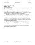
Section 3: Required Software, Sample Applications and Running an Application
3.1 CodeVision AVR Introduction and Initial Project Setup
There are numerous IDE’s available to use to program any of the AVR devices. For this project I
have chosen to focus on CoedVisionAVR. It is easy to use, reliable and efficient. Outlined throughout
this section are the steps needed to successfully install, start a new project and ultimately program the
MCU.
Begin by visiting http://www.hpinfotech.ro/html/cvavr.htm to download the evaluation (more
than adequate for our needs) of the software. Save the file and then double-click to execute once it has
finished downloading.
A directory must be created to store the files used in this example. Go to your “C” drive and
create a new fold named “STK500_TEST”. The location should read C:\STK500_TEST.
Once the download has completed and the software is installed; press the start menu, All
Programs, CodeVisionAVR folder and then select CodeVisionAVR C compiler Evaluation.
Figure 3.1.1: Start menu illustration to launch CodeVisionAVR.
Christopher S McCoy Fall 2009 Florida Gulf Coast University
Page 18
[INTRODUCTION TO MICROCONTROLLER PROGRAMMING AND
December 4, 2009 COMMUNICATION]
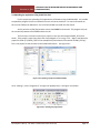
Next click File, New and a window will open (Figure 3.1.2). Select Project and click “Ok”(Figure 3.1.3).
Figure 3.1.2 and 3.1.3: New file and Create New File Screens.
Figure 3.1.4: Select “Yes” to confirm the start of the new project.
The window that opens now is the CodeWizardAVR Chip setup window. The first tab that is
open is to select Chip being used. Select ATmega8515L from the “Chip” dropdown. Make sure the
“Clock” setting is 3.6864MHz (the correct frequency for out MCU).
Christopher S McCoy Fall 2009 Florida Gulf Coast University
Page 19
[INTRODUCTION TO MICROCONTROLLER PROGRAMMING AND
December 4, 2009 COMMUNICATION]
Figure 3.1.5: Chip setup tab.
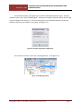
Next select the “Ports” tab. Select “PORTA” and make the settings match those of Figure 3.1.6.
The “PULLUP/OUTPUT” value must be changed from “T” to “P”. Once this is complete select “PORTC”.
Make sure your window matches the one as shown in Figure 3.1.7. In this case the “Data Direction”
must be changed from “In” to “Out” and the “Pull-up/Output” needs to be changed to “1”.
Figure 3.1.6: The default setting is on the left and the target settings are on the right.
Make your setting match those on the right.
Christopher S McCoy Fall 2009 Florida Gulf Coast University
Page 20
[INTRODUCTION TO MICROCONTROLLER PROGRAMMING AND
December 4, 2009 COMMUNICATION]
Figure 3.1.7: Default settings on the left; target settings on the right.
Make your settings match those of the right.
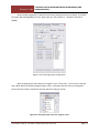
The next step is to select the “USART” tab and check both the “Receiver” and “Transmitter”
boxes. Next change the “Baud Rate” to 115200. Ensure you window matches those of Figure 3.1.8.
Figure 3.1.8: “USART” Tab; make sure your window matches this.
Christopher S McCoy Fall 2009 Florida Gulf Coast University
Page 21
[INTRODUCTION TO MICROCONTROLLER PROGRAMMING AND
December 4, 2009 COMMUNICATION]
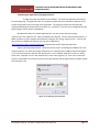
Figure 3.1.9: Go “File”, “Generate, Save and Exit” as shown above.
A window will open asking you to save a file. It is recommended that you use the same folder
for all files pertaining to the project. For this example we will use “STK500_TEST” as the name for all the
required files (the extensions will obviously be different). The following illustrations (Figure 3.1.10)
show these windows.
Figure 3.1.10: File save screens.
This concludes the software and project setup portion of this guide.
Christopher S McCoy Fall 2009 Florida Gulf Coast University
Page 22
[INTRODUCTION TO MICROCONTROLLER PROGRAMMING AND
December 4, 2009 COMMUNICATION]
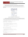
3.2 Basic Application Example
In CodeVisionAVR make sure that the “STK500_TEST.C” is open. Copy the following code into
this file.
#include <delay.h> // Contains “delay_ms()”
// Send the following message via USART communication
printf("USART Communication Test: Succeeded!!!\r\n");
// Check state of PORTA Pins
if(PINA != 0xFF) {
// If a button is pressed (input pulled low), toggle bits on PORTC
PORTC = ~PORTC;
// Send the following message via USART communication
printf("Hello!\r\n");
// Delay so flashing LED's are visible
delay_ms(1000);
printf("Goodbye!\r\n");
PORTC = ~PORTC;
}
Once this is complete, go to “File”, “Save all” to save the changes made to all files (Figure 3.2.1).
Next select “Project”, “Build All” to compile (Figure 3.2.1). This generates all the required files that will
be send to program the MCU in a later step. This should compile error free (Figure 3.3.2) but if for some
reason there are, you can see them in the “Errors” tab towards the bottom of the IDE (Figure 3.3.3).
Figure 3.2.1: “Save All” and “Build All”
Christopher S McCoy Fall 2009 Florida Gulf Coast University
Page 23
[INTRODUCTION TO MICROCONTROLLER PROGRAMMING AND
December 4, 2009 COMMUNICATION]
Figure 3.2.2: Build complete, no errors.
Figure 3.2.3: Any errors that might occur will be here.
Christopher S McCoy Fall 2009 Florida Gulf Coast University
Page 24
[INTRODUCTION TO MICROCONTROLLER PROGRAMMING AND
December 4, 2009 COMMUNICATION]
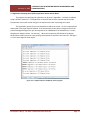
3.3Host PC Required Setup
Before we can test the connectivity we must make sure that the host PC is properly configured.
Specifically we need to make sure that the USB-RS232 convertor is properly configured. If the adapter
came with a driver CD make sure you insert and install the drivers. Once this is complete right-click on
“Computer”, select “Properties” and select “Device Manager” from the left hand side of the window
(Figure 3.3.1). In the “Device Manager” window select “Ports(COM & LPT)”. You should see in the drop
down “USB Serial Port (COM3)”. The COM number will likely be different as your computer may assign
this a different COM port (Figure 3.3.2). If you do not something similar to this then you adapter is not
installed correctly and need to follow the steps of this section again.
Figure 3.3.1: “Properties” and “Device Manager” shown above.
Figure 3.3.2: USB-RS232 adapter setup properly.
Christopher S McCoy Fall 2009 Florida Gulf Coast University
Page 25
[INTRODUCTION TO MICROCONTROLLER PROGRAMMING AND
December 4, 2009 COMMUNICATION]
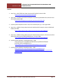
3.4 Uploading the Application Using CodeVision AVR
For this project the uploading of all applications will be done using CodeVisionAVR. It is possible
to upload the program from the command line but it will not be used here. For more information on
this see the STK500 User Manual for a list of all the needed command line information.
At this point the myTWI Temperature sensor should NOT be connected. This program only test
the connectivity between the STK500 and the host PC.
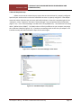
The first step is to make sure that your project (in this case the example STK500_TEST) from
earlier. If the project is open then skip to the next paragraph. If it is not go “File”, “Open” and select the
proper file folder (C:\STK500_TEST for the example here) and select the file named “STK500_TEST.prj”.
This is the project file that contains all the needed information. See Figure 3.4.1.
Figure 3.4.1: Opening a project in CodeVisionAVR.
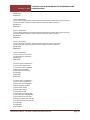
Go to “Settings”, select “Programmer” to begin the upload process. See Figure 3.4.1 below.
Figure 3.4.2: Starting the programmer.
Christopher S McCoy Fall 2009 Florida Gulf Coast University
Page 26
[INTRODUCTION TO MICROCONTROLLER PROGRAMMING AND
December 4, 2009 COMMUNICATION]
The window that opens now requires you to choose “AVR Chip Programmer Type”. From the
dropdown menu select “Atmel STK500/AVRISP”. Make sure the COM port matches that of what is listed
in device manager from section 3.3. This is the setting where your USB-RS232 adapter is so that the
software knows where to the MCU is connected. See Figure 3.4.3.
Figure 3.4.3: Proper Programmer configuration.
The next step is to select “Tools” then “Chip Programmer”. See Figure 3.4.4.
Figure 3.4.4: Chip Programmer
Christopher S McCoy Fall 2009 Florida Gulf Coast University
Page 27
[INTRODUCTION TO MICROCONTROLLER PROGRAMMING AND
December 4, 2009 COMMUNICATION]
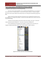
Once the Chip Programmer is open there are several settings that we must change. First select
the proper MCU (ATmega8515L for this). Next select the “SCK Frequency”. Default for our MCU is
230400.
Figure 3.4.5: Chip Programmer configuration.
With the programmer open select the “Program” menu, “Erase Chip”. This will ensure that the
chip is blank before we load the program (Figure 3.4.6). Erasing the chip each time you reprogram it
ensures that the memory used will be accurate and that nothing is corrupt.
Figure 3.4.6: Erase Chip option under the “Program” menu
Christopher S McCoy Fall 2009 Florida Gulf Coast University
Page 28
[INTRODUCTION TO MICROCONTROLLER PROGRAMMING AND
December 4, 2009 COMMUNICATION]
Next select the “Program” menu then “Flash”. This loads the current project HEX file onto the
MCU (Figure 3.4.7).
Figure 3.4.7: Flash option in the Chip Programmer.
This concludes the MCU programming. You can now close the Chip Programmer and
the CodeVisionAVR IDE if you would like and move on to the next section.
Christopher S McCoy Fall 2009 Florida Gulf Coast University
Page 29
[INTRODUCTION TO MICROCONTROLLER PROGRAMMING AND
December 4, 2009 COMMUNICATION]
3.5 Running the Application Using HyperTerminal
To begin press the reset button on the STK500. This resets the application and starts it
from the beginning. The application will run continuously while the unit is powered on because of the
infinite loop located in the main body of the application. This program requires that the board be
configured following the steps outlined in sections 2.1, 2.2 and 2.3. If the unit is not configured this way,
power it down and correct this immediately.
Windows Vista does not include HyperTerminal. You can correct this by extracting
“hypertrm.dll” and “hypertrm.exe” from any Windows XP computer. You can then place these files in a
folder anywhere on your computer and execute the program by running “hypertrm.exe”. If you do not
have access to a Windows XP machine you can visit my website at
http://satnet.fgcu.edu/~csmccoy/index.htm and download a zip file containing these files.
Begin by opening HyperTerminal. Name the current session, something like STK500_TEST, and
press ok (Figure 3.5.1). Select the proper COM port (in our examples this is COM3) and press OK (Figure
3.5.2). Press ok and ensure that the “Bits per Second” is set to 115200, “Data Bits” is set to 8, “Parity”
set to none, “Stop Bits” set to 1 and “Flow Control” set to none (Figure 3.5.3). Press “Ok” to continue.
Press the reset button on the PCB, press one of the push-buttons and the HyperTerminal window should
look like Figure 3.5.4.
Figure 3.5.1: Setting up the connection.
Christopher S McCoy Fall 2009 Florida Gulf Coast University
Page 30
[INTRODUCTION TO MICROCONTROLLER PROGRAMMING AND
December 4, 2009 COMMUNICATION]
Figure 3.5.2: Setting the COM port.
Figure 3.5.3: HyperTerminal port settings.
Figure 3.5.4: Successful execution of sample program.
Christopher S McCoy Fall 2009 Florida Gulf Coast University
Page 31
[INTRODUCTION TO MICROCONTROLLER PROGRAMMING AND
December 4, 2009 COMMUNICATION]
3.6 Sample Program implementing the myTWI Temperature Sensor
Begin by following the steps in Section 3.1 with a couple changes. Create a new directory to
store the project files in. For this example we’ll use C:\Temp_Example. Follow the steps listed in 3.1.
The exceptions to this is Select the tab “IC2”, “PORTE” and check “Enabled” under the “LM75” tab. See
figure 3.6.1.
Figure 3.6.1: Setting PORTE to use the temperature sensor.
Add the following code instead of that listed in Section 3.1. Once copied follow the steps listed
in Section 3.3 to save, compile and load the new program into the MCU. Next follow the steps in Section
3.5 to use HyperTerminal to execute. See Figure 3.6.2 for the proper output.
// Standard Input/Output functions
#include <stdio.h> // Contains "printf()" and sprintf()"
#include <delay.h> // Contains "delay_ms()"
#include <stdlib.h> // Contains "abs()"
/*
* The "int lm75_temperature_10(unsigned char chip)" function
* returns the temperature in degrees C times 10 retrieved from
* the LM75 sensor with the address "chip".
*
* CAUTION: A 300ms delay must be present between two successive
* calls to this function.
*/
// Get the temperature as an integer in degrees Celcius times 10
tempC_x10 = lm75_temperature_10(0);
PORTC = ~PORTC; // toggle LED values
//
//
//
//
Send the temperature data via USART
Divide by 10 to get the proper whole number temperature
Append the decimal value of the temperature to one place by
using modulus 10
printf("%-i.%-u",tempC_x10/10,abs(tempC_x10%10));
PORTC = ~PORTC;
// Delay for DELAY_ms amount of time
delay_ms(DELAY_ms);
Christopher S McCoy Fall 2009 Florida Gulf Coast University
Page 32
[INTRODUCTION TO MICROCONTROLLER PROGRAMMING AND
December 4, 2009 COMMUNICATION]
Figure 3.6.2: Correct output, in HyperTerminal, for the sample
application using the myTWI Temperature Sensor.
Christopher S McCoy Fall 2009 Florida Gulf Coast University
Page 33
[INTRODUCTION TO MICROCONTROLLER PROGRAMMING AND
December 4, 2009 COMMUNICATION]
3.7 Application Featuring the myTWI Temperature Sensor and DC Motor
The program incorporating this application can be seen in Appendix 1. Follow the hardware
setup outlined in Section 2.5. This application is based off the previous example with the myTWI
Temperature sensor with several changes to incorporate the motor and change the output.
This application reports the current temperature read by the sensor. It is then reported back
and printed in the HyperTerminal window. If the temperature read is above 27 degrees Celcius the
printed messaged changes from just the temperature to “WARNING!! The temperature is *current
temperature* degrees Celsius. Fan Starting.”. When the temperature falls below the 27 degree
threshold the output returns to simply printing the temperature and the motor shuts off. See Figure
3.7.1 for same HyperTerminal output.
Figure 3.7.1: Sample Output to modify the sensor program.
Christopher S McCoy Fall 2009 Florida Gulf Coast University
Page 34
[INTRODUCTION TO MICROCONTROLLER PROGRAMMING AND
December 4, 2009 COMMUNICATION]
Section 4: Conclusion
The basis of this project was to establish connection between a host PC and the AVR STK500 8bit microcontroller. This was accomplished through the example program in Section 3.4. The project
was then expanded to include the myTWI Temperature sensor in Section 3.6 with the code and
illustrations of the proper output. The last iteration on this project was to build on the temperature
sensor. This was done by including a small electric motor that would be activated based on the
temperature reading taken from the sensor. The application output changed based off this reading and
the motor was activated based on the reading.
The next step in expanding this project could be either by the addition of an LCD screen that
would also display the output. It would be a simple integration using the myAVR LCD add-on [6]. This is
a multi line LCD screen that can be customized to work with nearly anything. This could be coupled with
remote access through something like a webpage allowing the sensor to be monitored remotely as well
as on site.
The addition of the mySmartUSB MK2 USB-programmer would make the unit much more user
friendly. Serial is legacy technology and the USB-Serial adapters are notorious for their configuration
problems. It is nearly possible to find a host PC that comes standard with a serial port. USB, however, is
one of the most widely used I/O ports worldwide. It is on nearly every PC made. This ability would
greatly expand the market for this system.
Multi-platform support (for example Apple, Linux, etc.) would also be an option. Embedded
systems need to be flexible and having a system that has only been tested on a Windows based system
severely limits this flexibility. Taking the time to develop this would be highly beneficial.
Christopher S McCoy Fall 2009 Florida Gulf Coast University
Page 35
[INTRODUCTION TO MICROCONTROLLER PROGRAMMING AND
December 4, 2009 COMMUNICATION]
Citations
1. Atmel Corp., AVR STK500 User Guide, Revision 1925C-AVR-3/03, March 2003
< www.atmel.com/atmel/acrobat/doc1925.pdf >
2. Atmel Corp., 8-bit Microcontroller with 8K Bytes In-System Programmable Flash, Revision 2512JAVR-10/06, October 2006
< www.atmel.com/dyn/resources/prod_documents/doc2512.pdf >
3. myAVR, myTWI Temperature Sensor 1.02, Technical Description, pp. 1-10, August 2008
4. Atmel Corp., AVR033: Getting Started with the CodeVisionAVR C Compiler, Revision 2500C-AVR04/08, April 2008
< http://www.atmel.com/dyn/resources/prod_documents/doc2500.pdf >
5. Atmel Corp., AVR033: Getting Started with the CodeVisionAVR C Compiler, 8-bit Microcontrollers
Application Note, Revision 2500C-AVR-04/08, pp. 1-18, April 2008
< http://www.atmel.com/dyn/resources/prod_documents/doc2500.pdf >
6. myAVR, myAVR LCD add-on, Viewed December 1, 2009
< http://shop.myavr.com/Additional%20modules/myAVR%20LCD%20addon.htm?sp=article.sp.php&artID=15 >
< http://www.myavr.info/download/produkte/lcd/pb_lcd_de_en.pdf >
7. myAVR, mySmartUSB MK2, Viewed December 1, 2009
< http://shop.myavr.com/index.php?sp=article.sp.php&artID=42 >
< http://www.myavr.info/download/produkte/mysmartusb_mk2/pb_mysmartusbmk2_de_en.pdf >
Christopher S McCoy Fall 2009 Florida Gulf Coast University
Page 36
[INTRODUCTION TO MICROCONTROLLER PROGRAMMING AND
December 4, 2009 COMMUNICATION]
Appendix A: Source Code for Temperature Sensor and Motor Integration
•
The entire CodeVisionAVR project file is available for download at my website.
#include <mega8515.h>
// Standard Input/Output functions
#include <stdio.h> // Contains "printf()" and sprintf()"
#include <delay.h> // Contains "delay_ms()"
#include <stdlib.h> // Contains "abs()"
// I2C Bus functions
#asm
.equ __i2c_port=0x07 ;PORTE
.equ __sda_bit=0
.equ __scl_bit=1
#endasm
#include <i2c.h>
// LM75 Temperature Sensor functions
#include <lm75.h>
// Standard Input/Output functions
#include <stdio.h>
// Declare your global variables here
void main(void)
{
// Declare your local variables here
//variable to store the temperature taken from the sensor
int tempC_x10 = 0;
//1 second delay is taken between readings
int DELAY_ms = 1000;
//stores current temps, used to compare against maxTemp in order
//to determine if the fan should be enabled
int temp = 0;
//variable to hold max allowed temp before the fan should be enabled
int maxTemp = 0;
//variable used to enable/disable the fan operation
int flag = 0;
// Input/Output Ports initialization
// Port A initialization
// Func7=In Func6=In Func5=In Func4=In Func3=In Func2=In Func1=In Func0=In
// State7=P State6=P State5=P State4=P State3=P State2=P State1=P State0=P
Christopher S McCoy Fall 2009 Florida Gulf Coast University
Page 37
[INTRODUCTION TO MICROCONTROLLER PROGRAMMING AND
December 4, 2009 COMMUNICATION]
PORTA=0xFF;
DDRA=0x00;
// Port B initialization
// Func7=Out Func6=Out Func5=Out Func4=Out Func3=Out Func2=Out Func1=Out Func0=Out
// State7=1 State6=1 State5=1 State4=1 State3=1 State2=1 State1=1 State0=1
PORTB=0xFF;
DDRB=0xFF;
// Port C initialization
// Func7=Out Func6=Out Func5=Out Func4=Out Func3=Out Func2=Out Func1=Out Func0=Out
// State7=1 State6=1 State5=1 State4=1 State3=1 State2=1 State1=1 State0=1
PORTC=0xFF;
DDRC=0xFF;
// Port D initialization
// Func7=In Func6=In Func5=In Func4=In Func3=In Func2=In Func1=In Func0=In
// State7=T State6=T State5=T State4=T State3=T State2=T State1=T State0=T
PORTD=0x00;
DDRD=0x00;
// Port E initialization
// Func2=In Func1=In Func0=In
// State2=T State1=T State0=T
PORTE=0x00;
DDRE=0x00;
// Timer/Counter 0 initialization
// Clock source: System Clock
// Clock value: Timer 0 Stopped
// Mode: Normal top=FFh
// OC0 output: Disconnected
TCCR0=0x00;
TCNT0=0x00;
OCR0=0x00;
// Timer/Counter 1 initialization
// Clock source: System Clock
// Clock value: Timer1 Stopped
// Mode: Normal top=FFFFh
// OC1A output: Discon.
// OC1B output: Discon.
// Noise Canceler: Off
// Input Capture on Falling Edge
// Timer1 Overflow Interrupt: Off
// Input Capture Interrupt: Off
// Compare A Match Interrupt: Off
// Compare B Match Interrupt: Off
TCCR1A=0x00;
TCCR1B=0x00;
TCNT1H=0x00;
Christopher S McCoy Fall 2009 Florida Gulf Coast University
Page 38
[INTRODUCTION TO MICROCONTROLLER PROGRAMMING AND
December 4, 2009 COMMUNICATION]
TCNT1L=0x00;
ICR1H=0x00;
ICR1L=0x00;
OCR1AH=0x00;
OCR1AL=0x00;
OCR1BH=0x00;
OCR1BL=0x00;
// External Interrupt(s) initialization
// INT0: Off
// INT1: Off
// INT2: Off
MCUCR=0x00;
EMCUCR=0x00;
// Timer(s)/Counter(s) Interrupt(s) initialization
TIMSK=0x00;
// USART initialization
// Communication Parameters: 8 Data, 1 Stop, No Parity
// USART Receiver: On
// USART Transmitter: On
// USART Mode: Asynchronous
// USART Baud Rate: 115200
UCSRA=0x00;
UCSRB=0x18;
UCSRC=0x86;
UBRRH=0x00;
UBRRL=0x01;
// Analog Comparator initialization
// Analog Comparator: Off
// Analog Comparator Input Capture by Timer/Counter 1: Off
ACSR=0x80;
// I2C Bus initialization
i2c_init();
// LM75 Temperature Sensor initialization
// thyst: 75°C
// tos: 80°C
// O.S. polarity: 0
lm75_init(0,75,80,0);
//Create a flag variable, set it to 1 when the lights are enabled, once the temp
//falls below the threshold the application will exit the if loop and move on to
//where the flag will be reset.
while (1)
{
// Get the temperature as an integer in degrees Celcius times 10
Christopher S McCoy Fall 2009 Florida Gulf Coast University
Page 39
[INTRODUCTION TO MICROCONTROLLER PROGRAMMING AND
December 4, 2009 COMMUNICATION]
tempC_x10 = lm75_temperature_10(0);
// Send the temperature data via USART
// Divide by 10 to get the proper whole number temperature
// Append the decimal value of the temperature to one place by
// using modulus 10
temp = tempC_x10/10;
maxTemp = 27;
if(temp >= maxTemp){
printf("WARNING! Temperature is %-i.%-u degrees Celcius; fan
Starting.\n\n\r",tempC_x10/10,abs(tempC_x10%10));
//enable the port to start the motor
if(flag == 0){
PORTC = ~PORTC;
flag = 1;
}
}
else{
//disable or make sure the port is disabled and change flag value;
//temp is under the threshold of 27, the port should be off
if(flag == 1){
//disable the port and reset the flag
PORTC = ~PORTC;
flag = 0;
}
printf("The current temperature is %-i.%-u degrees Celcius.\n\n\r ",tempC_x10/10,abs(tempC_x10%10));
}
// Delay for DELAY_ms amount of time
delay_ms(DELAY_ms);
};
}
Christopher S McCoy Fall 2009 Florida Gulf Coast University
Page 40