1
8051 Demo Kit
Getting Started with the 8051
Microcontroller Development Tools
User’s Guide
ii
Keil Software
Information in this document is subject to change without notice and does not
represent a commitment on the part of the manufacturer. The software described
in this document is furnished under license agreement or nondisclosure agreement
and may be used or copied only in accordance with the terms of the agreement. It
is against the law to copy the software on any medium except as specifically
allowed in the license or nondisclosure agreement. The purchaser may make one
copy of the software for backup purposes. No part of this manual may be
reproduced or transmitted in any form or by any means, electronic or mechanical,
including photocopying, recording, or information storage and retrieval systems,
for any purpose other than for the purchaser’s personal use, without written
permission.
© Copyright 1990-1996 Keil Elektronik GmbH and Keil Software, Inc.
All rights reserved.
Keil C51™ and dScope™ are trademarks of Keil Elektronik GmbH.
Microsoft®, MS-DOS®, and Windows™ are trademarks or registered trademarks
of Microsoft Corporation.
IBM®, PC®, and PS/2® are registered trademarks of International Business
Machines Corporation.
Intel®, MCS® 51, ASM-51®, and PL/M-51® are registered trademarks of Intel
Corporation.
Every effort was made to ensure accuracy in this manual and to give appropriate
credit to persons, companies, and trademarks referenced herein.
A9 D05/11/96
Keil Software 8051 Demo Kit
iii
Preface
This manual is an introduction to the Keil Software 8051 microcontroller software
development tools. Itntroduces
i
new users and interested readers to our product
line. With nothing more than this book, you should be able to successfully run
and use our tools. This user’s guide contains the following chapters.
“Chapter 1. Introduction” gives an overview of this user’s guide.
“Chapter 2. Installation” describes how to install our software and how to setup
an operating environment for the tools.
“Chapter 3. 8051 Product Line
” discusses the different products that we offer for
the 8051 microcontroller. Read this chapter to determine which product provides
the tools you need.
“Chapter 4. 8051 Development Tools” describes the major features of our 8051
development tools including the C compiler, assembler, debugger, and integrated
development environment.
“Chapter 5 Using the 8051 tools
” describes the provided sample programs along
with a step-by-step guide that shows how to build them using our tools.
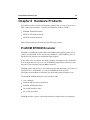
“Chapter 6 Hardware Products
” introduces our hardware-based tools that you
can use to aid in development and debugging. Our evaluation boards for the
80C517A and 87C520 and our EPROM emulator are discussed.
“Chapter 7 Real-Time Kernels
” discusses the RTX-51 Tiny and RTX-51 Full
real-time operating systems. This chapter provides an overview of multitasking
systems, why they are desirable, and how they are used.
“Chapter 8 Command Reference
” briefly describes the commands and controls
for our 8051 development tools.
NOTE
This manual assumes that you are familiar with Microsoft Windows and the
hardware and instruction set of the 8051 m
icrocontroller.
iv
Preface
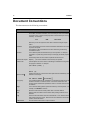
Document Conventions
This document uses the following conventions:
Examples
Description
README.TXT
Bold capital text is used for the names of executable programs, data files,
source files, environment variables, and commands you enter at the MS-DOS
command prompt. This text usually represents commands that you must type
in literally. For example:
CLS
DIR
BL51.EXE
Note that you are not required to enter these commands using all capital
letters.
Courier
Text in this typeface is used to represent information that displays on screen
or prints at the printer.
This typeface is also used within the text when discussing or describing
command line items.
Variables
Text in italics represents information that you must provide. For example,
projectfile in a syntax string means that you must supply the actual project file
name.
Occasionally, italics are also used to emphasize words in the text.
Elements that repeat… Ellipses (…) are used to indicate an item that may be repeated.
Omitted code
.
.
.
Optional Items
Vertical ellipses are used in source code listings to indicate that a fragment of
the program is omitted. For example:
void main (void) {
.
.
.
while (1);
Optional arguments in command-line and option fields are indicated by double
brackets. For example:
C51 TEST.C PRINT
(filename)
{ opt1 | opt2 }
Text contained within braces, separated by a vertical bar represents a group
of items from which one must be chosen. The braces enclose all of the
choices and the vertical bars separate the choices. One item in the list must
be selected.
Keys
Text in this sans serif typeface represents actual keys on the keyboard. For
example, “PressEnter to continue.”
Point
Move the mouse until the mouse pointer rests on the item desired.
Click
Quickly press and release a mouse button while pointing at the item to be
selected.
Drag
Press the left mouse button while on a selected item. Then, hold the button
down while moving the mouse. When the item to be selected is at the desired
position, release the button.
Double-Click
Click the mouse button twice in rapid succession.
Keil Software 8051 Demo Kit
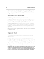
Contents
Chapter 1. Introduction................................ ................................ ................... 1
Manual Topics.........................................................................................................1
Evaluation and Demo Kits.......................................................................................2
Types of Users..........................................................................................................2
Changes to the Documentation.................................................................................3
Requesting Assistance..............................................................................................3
Chapter 2. Installation................................ ................................ ..................... 5
System Requirements...............................................................................................5
Backing Up Your Disks...........................................................................................6
Installing the Software.............................................................................................6
Directory Structure...................................................................................................7
Environment Settings...............................................................................................8
Improving System Performance
................................................................................9
Chapter 3. 8051 Product Line................................ ................................ ....... 11
8051 Development Tool Kits
..................................................................................11
Tool Kit Comparison Chart....................................................................................16
Chapter 4. 8051 Development Tools................................ ............................. 17
8051 Microcontroller Family..................................................................................17
C51 Optimizing C Cross Compiler
......................................................................... 18
A51 Macro Assembler............................................................................................33
BL51 Code Banking Linker/Locator
....................................................................... 35
OC51 Banked Object File Converter...................................................................... 38
OH51 Object-Hex Converter..................................................................................38
LIB51 Library Manager.........................................................................................38
dScope-51 for Windows.........................................................................................39
µVision/51 for Windows........................................................................................39
Chapter 5 Using the 8051 tools................................ ................................ ..... 41
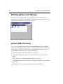
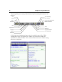
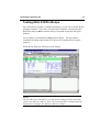
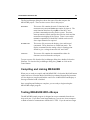
Starting µVision and dScope..................................................................................42
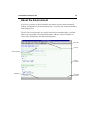
µVision IDE Overview...........................................................................................42
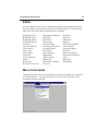
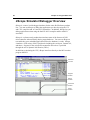
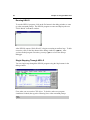
dScope Simulator/Debugger Overview
................................................................... 48
Sample Programs................................................................................................... 57
HELLO: Your First 8051 C Program.................................................................... 59
MEASURE: A Remote Measurement System
........................................................66
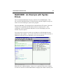
BADCODE: An Example with Syntax Errors.......................................................81
Chapter 6 Hardware Products................................ ................................ ...... 83
ProROM EPROM Emulator...................................................................................83
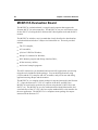
MCB517A Evaluation Board.................................................................................84
MCB520 Evaluation Board....................................................................................85
v
vi
Contents
Chapter 7 Real-Time Kernels................................ ................................ ........ 87
RTX-51 Real-Time Operating System................................................................... 87
Chapter 8 Command Reference
................................ ................................ .....97
A51 Macro Assemblers.......................................................................................... 97
C51 Compiler........................................................................................................ 98
L51/BL51 Linker/Locator.................................................................................... 100
OC51 Banked Object File Converter
.................................................................... 101
OH51 Object-Hex Converter................................................................................ 101
LIB51 Library Manager....................................................................................... 102
Index................................ ................................ ................................ ............. 103
Keil Software 8051 Demo Kit
1
Chapter 1. Introduction
Thank you for allowing Keil Software to provide you with software development
tools for the 8051 family of microcontrollers. With our tools, you can generate
embedded applications for the multitude of 8051 derivatives. Our 8051
development tools are listed below:
C51 Optimizing C Cross Compiler,
A51 Macro Assembler,
8051 Utilities (linker, object file converter, library manager),
dScope for Windows™ Source-Level Debugger/Simulator,
µVision for Windows™ Integrated Development Environment.
These tools are combined into the kits described in
Chapter
“
3. 8051 Product
Line” on page 11. The individual tools are described in detail inChapter
“
4.
8051 Development Tools” on page 17.
In addition to the above development tools, we also provide real-time kernels,
evaluation boards, and debugging hardware. Refer toChapter
“
7 Real-Time
Kernels” on page 87 and “Chapter 6 Hardware Products
” on page 83 for more
information about these products. Our tools are designed for the professional
software developer, but any level of programmer can use them to get the most out
of the 8051 hardware.
Manual Topics
This manual discusses a number of topics including how to:
Install the software on your system (seeChapter
“
2. Installation” on page 5)
and fine tune it for maximum performance (seeImproving
“
System
Performance” on page 9),
Select the best tool kit for your application (seeChapter
“
3. 8051 Product
Line” on page 11),
Use the 8051 development tools (seeChapter
“
4. 8051 Development Tools”
on page 17),
Run the included sample programs (seeChapter
“
5 Using the 8051 tools
” on
page 41).
2
Chapter 1. Introduction
If you want to get started immediately, you may do so by installing the software
(refer to “Chapter 2. Installation” on page 5) and running the sample programs
(refer to “Chapter 5 Using the 8051 tools
” on page 41). This is all you need to do
to begin using this kit.
Evaluation and Demo Kits
Keil Software provides two kits that let you evaluate our tools.
The C51 Demo Kit includes demonstration versions of our tools. The tools in the
Demo Kit do not generate actual object code. They generate listing files where
you can see the code generated by the compiler and other tools.
The C51 Evaluation Kitincludes evaluation versions of our tools. The tools in
the Evaluation Kit let you generate applications up to 2 Kbytes in size. You may
use this kit to evaluate the effectiveness of our tools and to generate small target
applications.
Both kits include this user’s guide and software. This user’s guide is also included
in each of our tool kits.
Types of Users
This manual addresses three types of users: evaluation users, new users, and
experienced users.
Evaluation Usersare those users who have not yet purchased the software but
have requested the evaluation package to get a better feel for what the tools do and
how they perform. The evaluation package includes evaluation copies of the
development tools. You may use the included sample programs to get real-world
experience with our 8051 development tools. Even if you are only a evaluation
user, take the time to read this manual. It explains how to install the software,
provides you with an overview of the development tools, and introduces the
sample programs.
New Users are those users who are purchasing our 8051 development tools for the
first time. The included software provides you with the latest development tool
versions as well as sample programs. If you are new to the 8051 or the tools, take
the time to review the sample programs described in this manual. This manual
Keil Software 8051 Demo Kit
3
provides a quick tutorial and helps new ornexperienced
i
users quickly get started
with the tools.
Experienced Usersare those users who have previously used our 8051
development tools and are now upgrading to the latest 8051 tools. The software
included with a product upgrade contains the latest development tools, the sample
programs, and a full set of manuals.
Changes to the Documentation
Last minute changes and corrections to the software and manuals are listed in the
README.TXT file which is included in the root directory of your insta
llation. Take
the time to read this file to determine if there are any changes that may
mpact
i
your installation.
Requesting Assistance
We are dedicated to providing you with the best embedded development tools and
documentation available. If you have suggestions or comments regarding any of
the printed manuals accompanying this product, please contact us. If you think
you have discovered a problem with the sof
tware, do the following before calling
technical support.
1. Read the sections in this manual that pertain to the job or task you are trying to
accomplish.
2. Make sure you are using the most current version of the software and utilities.
3. Isolate the problem to determine if it is a problem with the assembler, compiler,
linker, library manager, or another development tool.
4. Isolate software problems by reducing your code to a few lines.
If, after following these steps, you are still experiencing problems, report them to
our technical support group.
If you contact us by fax, be sure to include your name, your product serial number
and version number, and telephone numbers (voice and fax) where we can reach
you.
4
Chapter 1. Introduction
Try to be as detailed as possible when describing the problem you are having. The
more descriptive your example, the faster we can find a solution. If you have a
one-page code example demonstrating the problem, please fax it to us.
Keil Software 8051 Demo Kit
Chapter 2. Installation
This chapter explains how to setup an operating environment and how to install
the software on your hard disk. eBfore starting the installation program, you must
do the following:
Verify that your computer system meets the minimum requirements.
Make a copy of the installation diskette for backup purposes.
NOTE
This chapter refers to various MS-DOS commands which may be used to
customize your operating environment. TheSET and PATH commands, for
example, are used to initialize environment variables used by the compiler and
utilities. If you are not familiar with these commands and other MS-DOS
operations mentioned in this chapter, please refer to your DOS user’s guide.
System Requirements
There are minimum hardware and software requirements that must be satisfied to
ensure that the compiler and util
ities function properly.
For our Windows-based tools
, you must have the following:
100% IBM compatible 386 or higher PC,
Windows 3.1 or higher,
4 MB RAM minimum,
Hard disk with 6 MB free disk space.
For our DOS-based tools
, you must have the following:
100% IBM compatible 386 or higher PC with 640 KB RAM,
MS-DOS Version 3.1 or higher,
Hard disk with 6 MB free disk space.
5
6
Chapter 2. Installation
The C compiler and utilities require that you have at least 20 files and 20 buffers
defined in your CONFIG.SYS file. Additionally, you need enough environment
space for the environment variables used by the compiler and utilities (see
“Environment Settings
” on page 8).
Your
CONFIG.SYS
file should look similar to the following:
BUFFERS=20
FILES=20
SHELL=C:\COMMAND.COM /e:1024 /p
If you receive the messageOut of environment space from DOS, you can
increase the amount of environment space by increasing the number
1024 in the
above example. Refer to your DOS user’s guide for more information.
Backing Up Your Disks
We strongly suggest that you make a backup copy of the installation diskettes
using the DOS COPY or DISKCOPY commands. Then, use the backup disks to
install the software. Be sure to store the original disks in a safe place in case your
backups are lost or damaged.
Installing the Software
All of our products come with an installation program which allows easy
installation of our software.
Installing DOS-Based Products
To install DOS-based products, insert the first product diskette into Drive A and
enter the following command line at the DOS prompt:
A:INSTALL
Then, follow the instructions displayed by the installation program.
Keil Software 8051 Demo Kit
7
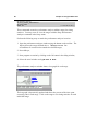
Installing Windows-Based Products
To install Windows-based products…
Insert the first product diskette into Drive A,
Select theRun… command from theFile menu in the Program Manager,
Enter A:SETUP at the Command Lineprompt,
Select theOK button.
Then, follow the instructions displayed by the installation program.
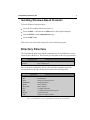
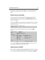
Directory Structure
The installation program copies the development tools into subdirectories of the
following base directories. The directory used depends on the kit being installed.
Directory
Description
\C51
8051 development tools.
\C51EVAL
8051 evaluation tools.
After creating the appropriate directory, the installation program copies the
development tools into the subdirectories listed in the following table.
Subdirectory
Description
…\ASM
Assembler include files.
…\BIN
Executable files.
…\DS51
dScope-51 for DOS IOF drivers.
…\EXAMPLES
Sample applications.
…\RTX51
RTX-51 Full files.
…\RTX_TINY
RTX-51 Tiny files.
…\INC
C compiler include files.
…\LIB
C compiler library files and startup code.
…\MON51
Target monitor files.
…\TS51
tScope-51 for DOS IOT drivers.
This table lists a complete installation that includes the entire line of 8051 deve
lopment
tools. Your installation may vary depending on the products you purchased.
8
Chapter 2. Installation
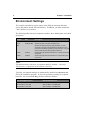
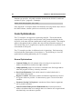
Environment Settings
The compiler and utilities require entries in the DOS environment table that
specify the path to include files and libraries. In addition, you must include the
…\BIN\ directory in your PATH.
The following table lists the environment variables, their default paths, and a brief
description.
Variable
Path
Description
PATH
\C51\BIN
Specifies the path of the 8051 development tools.
PATH
\C51EVAL\BIN
Specifies the path of the 8051 evaluation tools.
Specifies the path for temporary files generated. For best
performance, the path specified should be a RAM disk. If this
environment variable is specified, the path must exist. If the path
does not exist, the tools abort reporting a fatal error.
TMP
C51INC
\C51\INC
Specifies the path where the standard C51 compiler include files
are located.
C51LIB
\C51\LIB
Specifies the path where the standard C51 compiler library files
are located.
NOTE
This manual makes references to programs and files in the\C51\… directory.
This directory is equivalent to the \C51EVAL\… directory.
Typically, environment settings are automatically installed in your
AUTOEXEC.BAT
file by the installation program. If you wish to put these settings in a separate
batch file, the environment se
ttings must be entered as follows:
8051 Development Tools
8051 Evaluation Tools
PATH=C:\C51\BIN;...
PATH=C:\C51EVAL\BIN;...
SET C51INC=C:\C51\INC
SET C51INC=C:\C51EVAL\INC
SET C51LIB=C:\C51\LIB
SET C51LIB=C:\C51EVAL\LIB
Keil Software 8051 Demo Kit
9
Improving System Performance
There are two methods you can employ to improve performance of the C51
compiler and utilities. These techniques are generic and should help boost
performance of most appl
ications. You may:
Provide a RAM disk for the compiler and utilities to use for temporary files,
Use a disk cache to store the most recently accessed disk files.
Using a RAM Disk
If your computer has sufficient extended or expanded memory available, you
should consider using a RAM disk. A RAM disk is a memory-based disk
emulator. Because the contents of a RAM disk are stored in RAM, access is very
fast.
If you are using a RAM disk, you can set the value of the
TMP environment
variables to the drive name of the RAM disk. This speeds up the execution of the
many of the tools and utilities because they can use the RAM disk for temporary
files.
A number of RAM disk software packages are available.
RAMDRIVE.SYS and
VDISK.SYS are the names of the RAM disk programs that are most commonly
shipped with DOS. Refer to your DOS manual to learn how to install these
programs.
Using a Disk Cache
A disk cache utilizes a large memory pool to temporarily store information read
from disk. When the computer accesses the disk, it first checks the cache to see if
the desired information is already in the cache. If it is, the information is read
from the cache memory instead of from the disk. This is significantly faster than
waiting for the disk drive to read the information.
Typically, software development involves an edit-compile-edit-compile… cycle.
In these situations, a disk cache improves the performance of your editor,
assembler, compiler, and linker. The editor, the compiler, source file, and object
file can all be held in the cache, and disk accesses are kept to a minimum.
10
Chapter 2. Installation
Version 5.0 and Version 6.0 of MS-DOS both come with a disk-caching utility
called SMARTDRV.SYS. Refer to your DOS manual to learn how to install and use
this program.
Keil Software 8051 Demo Kit
11
Chapter 3. 8051 Product Line
Keil Software provides the premier 8051 development tools in the industry. To
help you become familiar with how we distribute our tools, we would like to
introduce the concept of a tool kit.
A tool kit is comprised of several application programs that you use to create your
8051 application. You may use an assembler to assemble your 8051 assembly
program, you may use a compiler to compile your C source code into an object
file, and you may use a linker to create an absolute object module suitable for your
in-circuit emulator.
While it makes little sense to have a compiler without a linker, it also makes little
sense to have a linker without a compiler or assembler. Therefore, our tools are
packaged into various kits.
Our 8051 kits are described below in the8051
“ Development Tool Kits
” section.
8051 Development Tool Kits
When you use the Keil Software tools, the 8051 project development cycle is
roughly the same as for any software development project.
1. Create source files in C or assembly.
2. Compile or assemble source files.
3. Correct errors in source files.
4. Link object files from compiler and assembler.
5. Test linked application.
12
Chapter 3. 8051 Product Line
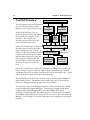
Tool Kit Overview
µVision/51
The development cycle described above
may be best illustrated by a block
C51
diagram of the complete 8051 tool set.
Compiler
As shown in this figure, files are
created by the µVision/51 IDE and then
passed to the C51 compiler or A51
C
assembler. The compiler and
Library
assembler process source files and
create relocatable object files.
A51 Macro
Assembler
LIB51
Library
Manager
RTX51
Real-Time
Operating
System
Object files created by the compiler andBL51 Linker for Code-Banking
assembler may be used by the LIB51
library manager to create a library. A
Emulator &
dScope-51
library is a specially formatted, ordered Source Leve -Debugger PROM Programmer
program collection of object modules
that the linker can process. When the
CPU &
linker processes a library, only the
Monitor-51
Peripheral
object modules in the library that are
Target Debugging
Simulator
necessary for program creation are
used.
Object files created by the compiler and assembler and library files created by the
library manager are processed by the linker to create an absolute object module.
An absolute object file or module is an object file with no relocatable code. All the
code in an absolute object file resides at fixed locations.
The absolute object file created by the linker may be used to program EPROM or
other memory devices. The absolute object module may also be used with the
dScope-51 debugger/simulator or with an in-circuit emulator.
The dScope-51 source level debugger/simulator is ideally suited for fast, reliable
high-level-language program debugging. The debugger contains a high-speed
simulator and a target debugger that let you simulate anntire
e 8051 system
including on-chip peripherals. By loading specific I/O drivers, you can simulate
the attributes and peripherals of a variety of 8051 derivatives. In conjunction with
Monitor-51, the debugger is even able to do source-level debugging on your target
hardware.
Keil Software 8051 Demo Kit
13
The RTX-51 real-time operating system is a multitasking kernel for the 8051
family. The RTX-51 real-time kernel simplifies the system design, programming,
and debugging of complex applications where fast reaction to time critical events
is essential. The kernel is fully integrated into the C51 compiler and is easy to
use. Task description tables and operating system consistency are automat
ically
controlled by the BL51 code banking linker/locator.
Tool Kit Introduction
The preceding diagram shows the full extent of the Keil Software 8051
development tools. The tools listed in this diagram comprise the professional
developer’s kit described on the following pages. In addition to the professional
kit, Keil Software provides a number of other tool kits for the 8051 developer. To
best illustrate what is included in each tool kit, we describe the kits in decreasing
order of capability. The most capable kit, the professional developer’s kit is
described first.
PK51-C51 Professional Developer’s Kit
The PK51 C51 professional developer’s kit includes everything the professional
8051 developer needs to create sophisticated embedded applications. This tool kit
includes the following components:
C51 Optimizing C Compiler,
A51 Macro Assembler,
BL51 Code Banking Linker/Locator,
OC51 Banked Object File Converter,
OH51 Object-Hex Converter,
LIB51 Library Manager,
dScope-51 Simulator/Debugger,
tScope-51 Target Debugger,
Monitor-51 ROM Monitor and Terminal Program,
Integrated Development Environment,
RTX-51 Tiny Real-Time Operating System.
14
Chapter 3. 8051 Product Line
In addition, the professional developer’s kit includes the following tools for
Windows users:
dScope-51 Simulator/Debugger for Windows,
µVision/51 Integrated Development Environment for Windows.
The professional developer’s kit can be configured for all 8051 derivatives. The
tools included in this kit run under DOS on any 100% IBM PC 386 or higher
compatible computer.
DK51-C51 Developer’s Kit
The DK51 C51 developer’s kit is designed for users who need a complete DOSbased development system for the 8051. This kit lets you create sophisticated
embedded applications using a DOS-based development platform. This tool kit
includes the following components:
C51 Optimizing C Compiler,
A51 Macro Assembler,
BL51 Code Banking Linker/Locator,
OC51 Banked Object File Converter,
OH51 Object-Hex Converter,
LIB51 Library Manager,
dScope-51 Simulator/Debugger,
tScope-51 Target Debugger,
Monitor-51 ROM Monitor and Terminal Program,
Integrated Development Environment.
The developer’s kit can be configured for all 8051 derivatives. The tools included
in this kit run under DOS on any 100% compatible IBM PC 386 or higher
computer.
Keil Software 8051 Demo Kit
15
CA51-C51 Compiler Kit
The CA51 C51 compiler kit is the best choice for developers who need a C
compiler but not a debugging system. This kit lets you create 8051 C applications
for your target hardware. The compiler kit can be configured for all 8051
derivatives. The tools included in this kit run under DOS on any 100%
compatible IBM PC 386 or higher computer.
A51-A51 Macro Assembler Kit
The A51 assembler kit includes our 8051 assembler and all the utilities you need
to begin creating 8051 application. The assembler kit is easily configured for all
8051 derivatives. The tools included in this kit run under DOS on any 100%
compatible IBM PC 386 or higher computer.
DS51-dScope-51 Simulator Kit
The DS51 simulator kit provides a debugger/simulator for use with the A51
assembler kit and the CA51 compiler kit. With this kit, you can quickly locate
problems in your 8051 application because the simulator lets you step through
your code one instruction at a time. You can easily view program variables,
SFRs, and memory locations. This tool kit includes the following components:
dScope-51 Simulator/Debugger,
tScope-51 Target Debugger,
Monitor-51 ROM Monitor and Terminal Program.
The simulator kit comes with drivers for most popular 8051 derivatives. The tools
included in this kit run under DOS on any 100% compatible IBM PC 386 or
higher computer.
FR51-RTX-51 Full Real-Time Kernel
The RTX-51 Full kernel is a real-time operating system for the 8051
microcontroller. RTX-51 Full provides a superset of the features found in RTX51 Tiny and also includes BITBUS and CAN communication protocol interface
libraries. Refer to “Chapter 7 Real-Time Kernels
” on page 87 for more
information about RTX-51 Tiny.
16
Chapter 3. 8051 Product Line
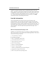
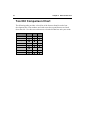
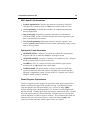
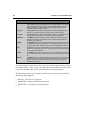
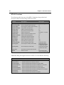
Tool Kit Comparison Chart
The following table provides a check list of the features found in each of our
development kits. Part numbers are listed across the top and features are listed
down the side. Use this cross reference to select the kit that best suits your needs.
Support
8051
Assembler
Compiler
Simulator
IDE
RTX
Windows
DOS
PK51
DK51
A51
Keil Software 8051 Demo Kit
17
Chapter 4. 8051 Development Tools
This chapter discusses the features and advantages of the 8051 micropro
cessor
family and the development tools available from Keil Software. We have designed
our development tools to help you quickly and successfully complete your job.
For this reason, our tools are easy to use and are guaranteed to help you achieve
your design goals.
8051 Microcontroller Family
The 8051 has been available since the early 1980’s. With a wide variety of
outstanding features and peripherals, the 8051 CPU core is destined to see service
well into the next century. More than 200 different 8051 derivatives are avai
lable
today from a variety of chip vendors. More than half of all embedded projects
with a CPU use members of the 8051 micr
ocontroller family. As an embedded
processor, the 8051 has no equal.
A typical 8051 family member contains the 8051 CPU core, data memory, code
memory, and some versatile peripheral functions. A flexible memoryrface
inte lets
you expand the capabilities of the 8051 using standard peripherals and memory
devices.
8051 Development Tools
Keil Software provides the following development tools for the 8051:
C51 Optimizing C Compiler (see page
18),
A51 Macro Assembler (see page33),
BL51 Code Banking Linker/Locator (see page
35),
OC51 Banked Object File Converter (see page
38),
OH51 Object-Hex Converter (see page
38),
LIB51 Library Manager (see page38)
dScope-51 for Windows (see page
39),
µVision/51 for Windows (see page
39).
18
Chapter 4. 8051 Development Tools
For information on the products which include these tools, refer Chapter
to “
3.
8051 Product Line” on page 11.
NOTE
All of our 8051 tools utilize the Intel OMF51object module format. The
development environment can be expanded with all Intel compatible tools such
as Intel PL/M-51 or iDCX-51 and with emulators from a wide range of
manufactures.
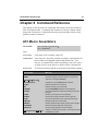
C51 Optimizing C Cross Compiler
The C programming language is a general-purpose programming language that
provides code efficiency, elements of structured programming, and a rich set of
operators. C is not abig language and is not designed for any one particular area
of application. Its generality, combined with its absence of restrictions, make C a
convenient and effective pr
ogramming solution for a wide variety of software
tasks. Many applications can be solved more easily and efficiently with C than
with other more specialized languages.
The Keil Software C51 optimizing cross compiler
for the MS-DOS operating
system is a complete implementation of the ANSI (American National Standards
Institute) standard for the C language. The C51 compiler generates code for the
8051 microprocessor but is not a universal C compiler adapted for the 8051
target. It is a ground-up implementation dedicated to generating extremely fast
and compact code for the 8051 microprocessor.
For most 8051 applications, the C51 compiler gives software developers the
flexibility of programming in C while matching the code efficiency and speed of
assembly language.
Using a high-level language like C has many advantages over assembly language
programming. For example:
Knowledge of the processor instruction set is not required. A rudimentary
knowledge of the 8051’s memory architecture is desirable but not necessary.
Register allocation and addressing mode details are managed by the compiler.
The ability to combine variable selection with specific operations improves
program readability.
Keil Software 8051 Demo Kit
19
Keywords and operational functions that more nearly resemble the human
thought process can be used.
Program development and debugging times are dramatically reduced when
compared to assembly language pr
ogramming.
The library files that are supplied provide many standard routines (such as
formatted output, data conversions, and floating-point arithmetic) that may be
incorporated into your application.
Existing routine can be reused in new programs by utilizing the modular
programming techniques avai
lable with C.
The C language is very portable and very popular. C compilers are available
for almost all target systems. Existing softwarenvestments
i
can be quickly
and easily converted from or adapted to other processors or env
ironments.
C51 Language Extensions
The C51 compiler is an ANSI compliant C compiler and includes all aspects of
the C programming language that are specified by the ANSI standard. A number
of extensions to the C programming language are provided to support the facilities
of the 8051 microproce
ssor. The C51 compiler includes extensions for:
Data Types,
Memory Types,
Memory Models,
Pointers,
Reentrant Functions,
Interrupt Functions,
Real-Time Operating Systems,
Interfacing to PL/M and A51 source files.
The following sections briefly describe these extensions.
20
Chapter 4. 8051 Development Tools
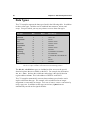
Data Types
The C51 compiler supports the data types listed in the following table. In addition
to these scalar types, variables can be combined into structures, unions, and
arrays. Except as noted, you may use pointers to access these data types.
Data Type
Bits
Bytes
Value Range
bit †
1
signed char
8
1
0 to 1
-128 to +127
unsigned char
8
1
0 to 255
enum
16
2
-32768 to +32767
signed short
16
2
-32768 to +32767
unsigned short
16
2
0 to 65535
signed int
16
2
-32768 to +32767
unsigned int
16
2
0 to 65535
signed long
32
4
-2147483648 to 2147483647
unsigned long
32
4
0 to 4294967295
float
32
4
±1.175494E-38 to ±3.402823E+38
sbit †
1
0 to 1
sfr †
8
1
0 to 255
sfr16 †
16
2
0 to 65535
† The bit, sbit, sfr, and sfr16 data types are specific to the 8051 hardware and the C51 compiler.
The are not a part of ANSI C and cannot be accessed through pointers.
The sbit, sfr, and sfr16 data types are included to allow access to the special
function registers that are available on the 8051. For example, the declaration:
sfr P0 = 0x80; declares the variable P0 and assigns it the special function
register address of 0x80. This is the address of PORT 0 on the 8051.
The C51 compiler automatically converts between data types when the result
implies a different data type. For example, a bit variable used in an integer
assignment is converted to an integer. You can, of course, coerce a conversion by
using a type cast. In addition to data type conversions, sign
xtensions
e
are
automatically carried out for signed variables.
Keil Software 8051 Demo Kit
21
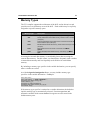
Memory Types
The C51 compiler supports the architecture of the 8051 and its derivatives and
provides access to all memory areas of the 8051. Each variable may be explicitly
assigned to a specific memory space.
Memory Type
Description
code
Program memory (64 Kbytes); accessed by opcode
MOVC @A+DPTR.
data
Directly addressable internal data memory; fastest access to variables
(128 bytes).
idata
Indirectly addressable internal data memory; accessed across the full
internal address space (256 bytes).
bdata
Bit-addressable internal data memory; allows mixed bit and byte access
(16 bytes).
xdata
External data memory (64 Kbytes); accessed by opcode
MOVX
@DPTR.
pdata
Paged (256 bytes) external data memory; accessed by opcode
MOVX
@Rn.
Accessing the internal data memory is considerably faster than accessing the
external data memory. For this reason, you should place frequently used variables
in internal data memory and less frequently used variables in external data
memory.
By including a memory type specifier in the variable declaration, you can specify
where variables are stored.
As with thesigned and unsignedattributes, you may include memory type
specifiers in the variable declaration. Forxample:
e
char data var1;
char code text[] = "ENTER PARAMETER:";
unsigned long xdata array[100];
float idata x,y,z;
unsigned int pdata dimension;
unsigned char xdata vector[10][4][4];
char bdata flags;
If the memory type specifier is omitted in a variable declaration, the default or
implicit memory type is automatically selected. Function arguments and
automatic variables which cannot beocated
l
in registers are also stored in the
default memory area.
22
Chapter 4. 8051 Development Tools
The default memory type is determined by the
SMALL, COMPACT and
LARGE compiler control directives. These directives specify the memory model
to use for the compilation.
Memory Models
The memory model determines the default memory type used for function
arguments, automatic variables, and variables declared with no explicit memory
type. You specify the memory model on the command line usingSMALL,
the
COMPACT, and LARGE control directives. By explicitly declaring a variable
with a memory type specifier, you may override the default memory type.
SMALL
In this model, all variables default to the internal data memory of
the 8051. This is the same as if they were declared explicitly
using thedata memory type specifier. In this memory model,
variable access is very efficient. However, all data objects, as
well as the stack must fit into the internal RAM. Stack size is
critical because the stack space used depends upon the nesting
depth of the various functions. Typically, if the BL51 code
banking linker/locator is configured to overlay variables in the
internal data memory, the small model is the best model to use.
COMPACT
Using compact model, all variables default to one page of external
data memory. This is the same as if they were explicitly declared
using thepdata memory type specifier. This memory model can
accommodate a maximum of 256 bytes of variables. The
limitation is due to the addressing scheme used, which is indirect
through registers R0 and R1. This memory model is not as
efficient as the small model, therefore, variable access is not as
fast. However, the compact model is faster than the large model.
The high byte of the address is usually set up via port 2. The
compiler does not set this port for you.
LARGE
In large model, all variables default to external data me
mory.
This is the same as if they were explicitly declared using the
xdata memory type specifier. The data pointerDPTR)
(
is used
for addressing. Memory access through this data pointer is
inefficient, especially for variables with a length of two or more
bytes. This type of data access generates more code than the
small or compact models.
Keil Software 8051 Demo Kit
23
NOTE
You should always use theSMALL memory model. It generates the fastest,
tightest, and most efficient code. You can always explicitly specify the memory
area for variables. Move up in model size only if you are unable to make your
application fit or operate usingSMALL model.
Pointers
The C51 compiler supports pointer declarations using the asterisk character (‘*’).
You may use pointers to perform all operations available in standard C. However,
because of the unique architecture of the 8051 and its derivatives, the C51
compiler supports two different types of pointers: memory specific pointers and
generic pointers.
Generic Pointers
Generic pointers are declared in the same way as standard C pointers. For
example:
char *s;
int *numptr;
long *state;
/* string ptr */
/* int ptr */
/* long ptr */
Generic pointers are always stored using three bytes. The first byte is for the
memory type, the second is for the high-order byte of the offset, and the third is for
the low-order byte of the offset.
Generic pointers may be used to access any variable regardless of its location in
8051 memory space. Many of the library routines use these pointer types for this
reason. By using these generic untyped pointers, a function can access data
regardless of the memory in which it is stored.
Memory Specific Pointers
Memory specific pointers always include a memory type specification in the
pointer declaration and always refer to a specific memory area. For exa
mple:
char data *str;
int xdata *numtab;
long code *powtab;
/* ptr to string in data */
/* ptr to int(s) in xdata */
/* ptr to long(s) in code */
24
Chapter 4. 8051 Development Tools
Because the memory type is specified at compile-time, the memory type byte
required by untyped pointers is not needed by typed pointers. Typed pointers can
be stored using only one byteidata,
(
data, bdata, and pdata pointers) or two
bytes (code and xdata pointers).
Comparison: Memory Specific & Generic Pointers
You can significantly accelerate an 8051 C program by using ‘memory specific’
pointers. The following sample program shows the differences in code & data size
and execution time for various pointer declar
ations.
Description
Idata Pointer
Xdata Pointer
Generic Pointer
Sample Program
char idata *ip;
char val;
val = *ip;
char xdata *xp;
char val;
val = *xp;
char *p;
char val;
val = *p;
8051 Program Code
Generated
MOV
MOV
MOV
MOV
MOV
MOV
MOV
MOV
MOV
CALL
Pointer Size
1 byte data
2 bytes data
3 bytes data
Code Size
4 bytes code
9 bytes code
11 bytes code + Lib.
Execution Time
4 cycles
7 cycles
13 cycles
R0,ip
val,@R0
DPL,xp +1
DPH,xp
A,@DPTR
val,A
R1,p + 2
R2,p + 1
R3,p
CLDPTR
Reentrant Functions
A reentrant function can be shared by several processes at the same time. When a
reentrant function is executing, another process can interrupt the execution and
then begin to execute that same reentrant function. Normally, C51 functions
cannot be called er cursively or in a fashion which causes reentrancy. The reason
for this limitation is that function arguments and local variables are stored in fixed
memory locations. Thereentrant function attribute allows you to declare
functions that may be reentrant and, ther
efore, may be called recursively. For
example:
int calc (char i, int b) reentrant
{
int x;
x = table [i];
return (x * b);
}
Reentrant functions can be called recursively and can be called
simultaneouslyby
two or more processes. Reentrant functions are often required in real-time
Keil Software 8051 Demo Kit
25
applications or in situations where interrupt code and non-interrupt code must
share a function.
For each reentrant function, a reentrant stack area is simulated in internal or
external memory depending on the memory model.
NOTE
By selecting the reentrant attribute on a function by function basis, you can
select the use of this attribute where it’s needed without making the entire
program reentrant. Making an entire program reentrant may cause it to be
larger and consume more memory.
Interrupt Functions
The C51 compiler provides you with a method of calling a C function when an
interrupt occurs. This support allows you to create interrupt service routines in C.
You need only be concerned with the interrupt number and register bank selection.
The compiler automatically generates the interrupt vector and entry and exit code
for the interrupt routine. Theinterrupt function attribute, when included in a
declaration, specifies that the ass
ociated function is an interrupt function.
Additionally, you can specify the register bank used for that interrupt with the
using function attribute.
unsigned int interruptcnt;
unsigned char second;
void timer0 (void) interrupt 1 using 2 {
if (++interruptcnt == 4000) {
second++;
interruptcnt = 0;
}
}
/* count to 4000 */
/* second counter */
/* clear int counter */
Parameter Passing
The C51 compiler passes up to three function arguments in CPU registers. This
significantly improves system performance since arguments do not have to be
written to and read from memory. Argument passing can be controlled with the
REGPARMS and NOREGPARMS control directives.
26
Chapter 4. 8051 Development Tools
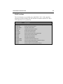
The following table lists the registers used for different arguments and data types.
Argument
Number
char,
1-byte pointer
int,
2-byte pointer
long,
float
generic
pointer
1
R7
R6 & R7
R4 - R7
R1 - R3
2
R5
R4 & R5
3
R3
R2 & R3
If no registers are available for argument passing or too many arguments are
involved, fixed memory locations are used for those extra arguments.
Function Return Values
CPU registers are always used for function return values. The following table
lists the return types and the registers used for each.
Return Type
Register
Description
bit
Carry Flag
char, unsigned char, 1-byte pointer
R7
int, unsigned int, 2-byte pointer
R6 & R7
MSB in R6, LSB in R7
long, unsigned long
R4 - R7
MSB in R4, LSB in R7
float
R4 - R7
32-Bit IEEE format
generic pointer
R1 - R3
Memory type in R3, MSB R2, LSB R1
Register Optimizing
Depending on program context, the C51 compiler allocates up to 7 CPU registers
for register variables. Any registers modified during function execution are noted
by the C51 compiler within each module. The linker/locator generates a global,
project-wide register file which contains information of all registers altered by
external functions. Consequently, the C51 compiler
knows the register used by
each function in an application and can optimize the CPU register alloc
ation of
each C function.
Real-Time Operating System Support
The C51 compiler integrates well with both the RTX-51 Full and RTX-51 Tiny
multitasking real-time operating systems. The task description tables are
Keil Software 8051 Demo Kit
27
generated and controlled during the link pro
cess. For more information about the
RTX real-time operating systems, refer toChapter
“
7 Real-Time Kernels
” on
page 87.
Interfacing to Assembly
You can easily access assembly routines from C and vice versa. Function
parameters are passed via CPU registers or, if the
NOREGPARMS control is
used, via fixed memory locations. Values returned from functions are always
passed in CPU registers.
You can use theSRC directive to direct the C51 compiler to generate a file ready
to assemble with the A51 assembler instead of an object file. For example, the
following C source file:
unsigned int asmfunc1 (unsigned int arg){
return (1 + arg);
}
generates the following assembly output file when compiled usingSRC
the
directive.
?PR?_asmfunc1?ASM1
PUBLIC
SEGMENT CODE
_asmfunc1
RSEG ?PR?_asmfunc1?ASM1
USING 0
_asmfunc1:
;---- Variable 'arg?00'
MOV
ADD
MOV
CLR
ADDC
MOV
assigned to Register 'R6/R7'
A,R7
; load LSB of
A,#01H
; add 1
R7,A
; put it back
A
A,R6
; add carry &
R6,A
---the int
into R7
R6
?C0001:
RET
; return result in R6/R7
You may use the#pragma asmand #pragma endasmpreprocessor directives to
insert assembly instructions into your C source code.
Interfacing to PL/M-51
Intel’s PL/M-51 is a popular programming language that is similar to C in many
ways. You can easily interface routines written in C to routines written in PL/M51. You can access PL/M-51 functions from C by declaring them with alien
the
28
Chapter 4. 8051 Development Tools
function type specifier. All public variables declared in the PL/M-51 module are
available to your C programs. For xample:
e
extern alien char plm_func (int, char);
Since the PL/M-51 compiler and the Keil Software tools all generate object files in
the OMF51format, external symbols are resolved by the linker.
Code Optimizations
The C51 compiler is an aggressive optimizing compiler. This means that the
compiler takes certain steps to ensure that the code generated and output to the
object file is the most efficient (smaller and/or faster) code possible. The compiler
analyzes the generated code to produce the most efficient instruction sequences.
This ensures that your C program runs as quickly and effectively as possible in the
least amount of code space.
The C51 compiler provides six different levels of optimizing. Each increasing
level includes the optimizations of levels below it. The following is a list of all
optimizations currently pe
rformed by the C51 compiler.
General Optimizations
Constant Folding: Several constant values occurring in an expression or
address calculation are combined as a ngle
si constant.
Jump Optimizing: Jumps are inverted or extended to the final target address
when the program efficiency is thereby increased.
Dead Code Elimination
: Code which cannot be reached (dead code) is
removed from the program.
Register Variables: Automatic variables and function arguments are located
in registers whenever possible. No data memory space is reserved for these
variables.
Parameter Passing Via Registers
: A maximum of three function arguments
can be passed in registers.
Global Common Subexpression Elimination
: Identical subexpressions or
address calculations that occur multiple times in a function are recognized and
calculated only once whenever possible.
Keil Software 8051 Demo Kit
29
8051-Specific Optimizations
Peephole Optimization
: Complex operations are replaced by simplified
operations when memory space or exec
ution time can be saved as a result.
Access Optimizing: Constants and variables are computed and included
directly in operations.
Data Overlaying: Data and bit segments of functions are identified as
OVERLAYABLE and are overlaid with other data and bit segments by the
BL51 code banking linker/locator.
Case/Switch Optimizing
: Depending upon their number, sequence, and
location, switch and case statements can be further optimized by using a jump
table or string of jumps.
Options for Code Generation
OPTIMIZE(SIZE): Common C operations are replaced by subprograms.
Program code size is reduced at thexpense
e
of program speed.
OPTIMIZE(SPEED): Common C operations are expanded in-line. Program
speed is increased at the expense of code size.
NOAREGS: The C51 compiler no longer uses absolute register access.
Program code is independent of the register bank.
NOREGPARMS: Parameter passing is always performed in local data
segments rather then dedicated registers. Program code created with this
#pragma is compatible to earlier versions of the C51 compiler, the PL/M-51
compiler, and the ASM-51 assembler.
Global Register Optimization
The C51 compiler provides support for application wide register optimization
which is also known as application register coloring. The following sample
program compares the code generated by C51 version 5.0 using applic
ation
register coloring to the code generated by C51 version 3.4 without application
register coloring. With the application wide register optimization, the C compiler
knows the registers used by external functions. Registers that are not altered in
external functions are used for register variables. The generated code needs less
data and code space and executes faster. In the following example
input and
output are external functions, which require only a few registers.
30
Chapter 4. 8051 Development Tools
With Global Register Optimization
main () {
unsigned char i;
unsigned char a;
while (1) {
i = input ();
?C0001:
LCALL
input
;- 'i' assigned to 'R6' MOV
R6,AR7
do {
a = input ();
?C0005:
LCALL
input
;- 'a' assigned to 'R7' MOV
R5,AR7
output (a);
LCALL
_output
} while (--i);
DJNZ
R6,?C0005
SJMP
?C0001
Without Global Register Optimization
/* get number of values */
?C0001:
LCALL
MOV
MOV
MOV
input
DPTR,#i
A,R7
@DPTR,A
/* get input value */
?C0005:
LCALL
MOV
MOV
MOVX
input
DPTR,#a
A,R7
@DPTR,A
/* output value */
LCALL
_output
/* decrement values */
MOV
MOVX
DEC
MOVX
JNZ
DPTR,#i
A,@DPTR
A
@DPTR,A
?C0005
SJMP
?C0001
}
}
RET
Code Size: 18 Bytes
RET
Code Size: 30 Bytes
Debugging
The C51 compiler uses the Intel Object Format (OMF51
) for object files and
generates complete symbol information. Additionally, the compiler can include all
the necessary information such as; var
iable names, function names, line numbers,
and so on to allow detailed and thoroughebugging
d
and analysis with dScope-51
or Intel compatible emulators. All Intel compatible emulators may be used for
program debugging. In addition, theOBJECTEXTEND control directive
embeds additional variable type information in the object file which allows typespecific display of variables and structures when using certain emulators. You
should check with your emulator vendor to determine if it is compatible with the
Intel OMF51object module format and if it can accept Keil object modules.
Keil Software 8051 Demo Kit
31
Library Routines
The C51 compiler includes seven different ANSI compile-time libraries which are
optimized for various functional requirements.
Library File
Description
C51S.LIB
Small model library without floating-point arithmetic
C51FPS.LIB
Small model floating-point arithmetic library
C51C.LIB
Compact model library without floating-point arithmetic
C51FPC.LIB
Compact model floating-point arithmetic library
C51L.LIB
Large model library without floating-point arithmetic
C51FPL.LIB
Large model floating-point arithmetic library
80C751.LIB
Library for use with the Philips 8xC751 and derivatives.
Source code is provided for library modules that perform hardware-related I/O and
is found in the \C51\LIB directory. You may use these source files to help you
quickly adapt the library to perform I/O using any I/Oevice
d in your target.
Intrinsic Library Routines
The libraries included with the compiler include a number of routines that are
implemented as intrinsic fun
ctions. Non-intrinsic functions generate
ACALL or
LCALL instructions to perform the library routine. Intrinsic functions generate
in-line code (which is faster and more efficient) to perform the library routine.
Intrinsic Function
Description
_crol_
Rotate character left.
_cror_
Rotate character right.
_irol_
Rotate integer left.
_iror_
Rotate integer right.
_lrol_
Rotate long integer left.
_lror_
Rotate long integer right.
_nop_
No operation (8051 NOP instruction).
_testbit_
Test and clear bit (8051 JBC instruction).
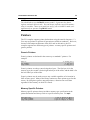
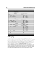
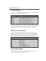
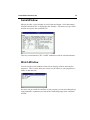
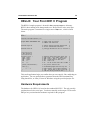
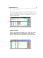
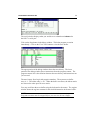
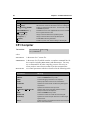
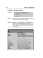
Listing File Example
The C51 compiler produces a listing file that contains source code, directive
information, an assembly listing, and a symbol table.
32
Chapter 4. 8051 Development Tools
C51 COMPILER V5.02,
SAMPLE
07/01/95
08:00:00
PAGE 1
DOS C51 COMPILER V5.02, COMPILATION OF MODULE SAMPLE
OBJECT MODULE PLACED IN SAMPLE.OBJ
COMPILER INVOKED BY: C:\C51\BIN\C51.EXE SAMPLE.C CODE
stmt level source
1
#include <reg51.h>
/* SFR definitions for 8051 */
2
#include <stdio.h>
/* standard i/o definitions */
3
#include <ctype.h>
/* defs for char conversion */
4
5
#define EOT 0x1A
/* Control+Z signals EOT */
6
7
void main (void) {
8
1
unsigned char c;
9
1
10
1
/* setup serial port hdw (2400 Baud @12 MHz) */
11
1
SCON = 0x52;
/* SCON */
12
1
TMOD = 0x20;
/* TMOD */
13
1
TCON = 0x69;
/* TCON */
14
1
TH1 = 0xF3;
/* TH1 */
15
1
16
1
while ((c = getchar ()) != EOF) {
17
2
putchar (toupper (c));
18
2
}
19
1
P0 = 0;
/* clear Output Port to signal ready */
20
1
}
The C51 compiler produces a
listing file with page numbers
as well as time and date of
the compilation. Remarks
about the compiler invocation
and object file output are
displayed in this listing.
The listing includes a line
number for each statement
and a nesting level for each
block enclosed within curly
braces (‘{‘ and ‘}’).
Error messages and
warning messages are
included in the listing file.
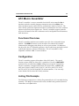
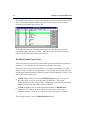
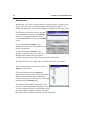
ASSEMBLY LISTING OF GENERATED OBJECT CODE
; FUNCTION main (BEGIN)
; SOURCE LINE # 7
; SOURCE LINE # 11
0000 759852
MOV
SCON,#052H
0003 758920
MOV
TMOD,#020H
0006 758869
MOV
TCON,#069H
0009 758DF3
000C
MOV
?C0001:
TH1,#0F3H
000C
000F
0011
0012
0013
120000
8F00
EF
F4
6008
E
R
LCALL
MOV
MOV
CPL
JZ
getchar
c,R7
A,R7
A
?C0002
0015 120000
0018 120000
E
E
LCALL
LCALL
_toupper
_putchar
001B 80EF
001D
SJMP
?C0002:
; SOURCE LINE # 12
; SOURCE LINE # 13
The CODE compiler option
includes an assembly code
listing in the listing file.
Source line numbers are
embedded within the
generated code.
; SOURCE LINE # 14
; SOURCE LINE # 16
; SOURCE LINE # 17
; SOURCE LINE # 18
?C0001
; SOURCE LINE # 19
001D E4
001E F580
CLR
MOV
A
P0,A
; SOURCE LINE # 20
0020 22
RET
; FUNCTION main (END)
MODULE INFORMATION:
STATIC OVERLAYABLE
CODE SIZE
=
33
---CONSTANT SIZE
=
------XDATA SIZE
=
------PDATA SIZE
=
------DATA SIZE
=
---1
IDATA SIZE
=
------BIT SIZE
=
------END OF MODULE INFORMATION.
C51 COMPILATION COMPLETE.
0 WARNING(S),
A memory overview provides
information about the 8051
memory areas that are used.
0 ERROR(S)
The total number of errors
and warnings is stated at
the end of the listing file.
Keil Software 8051 Demo Kit
33
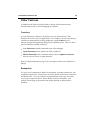
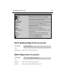
A51 Macro Assembler
The A51 assembler is a macro assembler for the 8051 microcontroller fam
ily. It
translates symbolic assembly language mnemonics into relocatable
bject
o code
where the utmost speed, small code size, and hardware control are critical. The
macro facility speeds development and conserves maintenance time since common
sequences need only be developed once. The A51 assembler supports symbolic
access to all features of the 8051 architecture and is configurable for the numerous
8051 derivatives.
Functional Overview
The A51 assembler translates an assembler source file into a relocatable object
module. If theDEBUG control is used, the object file contains full symbolic
information for debugging with dScope or an in-circuit emulator. In addition to
the object file, the A51 assembler generates a list file which may optionally include
symbol table and cross reference information. The A51 assembler is fully
compatible with Intel ASM-51 source modules.
Configuration
The A51 assembler supports all members of the 8051 family. The special
function register (SFR) set of the 8051 is predefined. However, the
NOMOD51
control lets you override these defin
itions with processor-specific include files.
The A51 assembler is shipped with include files for the 8051, 8051F
x, 8051GB,
8052, 80152, 80451, 80452, 80515, 80C517, 80C515A, 80C517A, 8x552,
8xC592, 8xCL781, 8xCL410 and 80C320 microcontrollers. You can easily
create include files for other 8051 family members.
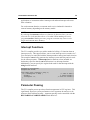
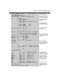
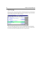
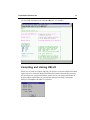
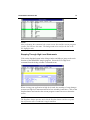
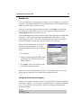
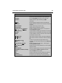
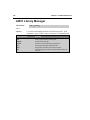
Listing File Example
The following example shows a listing file generated by the A51 assembler during
assembly. The listing file contains source code, machine code generated, directive
information, and a symbol table.
34
Chapter 4. 8051 Development Tools
A51 MACRO ASSEMBLER
Test Program
07/01/95 08:00:00 PAGE
1
DOS MACRO ASSEMBLER A51 V5.02
OBJECT MODULE PLACED IN SAMPLE.OBJ
ASSEMBLER INVOKED BY: C:\C51\BIN\A51.EXE SAMPLE.A51 XREF
LOC
---0000
---0000
0003
0005
0008
000B
000E
---0000
0004
0008
000C
---0000
OBJ
LINE
1
2
3
4
5
6
7
8
9
10
11
12
020000
F 13
14
15
16
120000
F 17
18
19
20
C200
F 21
900000
F 22
120000
F 23
120000
F 24
80F5
25
26
27
54455354
28
2050524F
4752414D
00
29
30
31
32
33
34
35
SOURCE
$TITLE ('Test Program')
NAME
SAMPLE
EXTRN CODE (PUT_CRLF, PUTSTRING, InitSerial)
PUBLIC TXTBIT
PROG
CONST
BITVAR
Reset:
SEGMENT
SEGMENT
SEGMENT
CODE
CODE
BIT
CSEG
AT
JMP
Start
RSEG
; *****
Start: CALL
0
Typical programs start
with EXTERN, PUBLIC,
and SEGMENT directives.
The listing file includes a
line number for each
source line.
PROG
InitSerial ;Init Serial Interface
; This is the main program. It is an endless
; loop which displays a text on the console.
CLR
TXTBIT
; read from CODE
Repeat: MOV
DPTR,#TXT
CALL PUTSTRING
CALL PUT_CRLF
SJMP Repeat
;
RSEG CONST
TXT:
DB
'TEST PROGRAM',00H
RSEG
TXTBIT: DBIT
The A51 assembler
produces a listing file with
page numbers as well as
the time and date of the
assembly. Remarks about
the assembler invocation
and the object file output
are displayed in this
listing.
BITVAR
1
If a source line generates
code, the HEX values are
displayed at the beginning
of the line.
Error messages and
warning messages are
included in the listing file.
The position of each error
is clearly marked.
; TXTBIT=0 read from CODE
; TXTBIT=1 read from XDATA
END
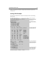
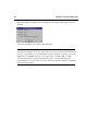
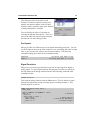
XREF SYMBOL TABLE LISTING
---- ------ ----- ------N A M E
BITVAR . .
CONST. . .
INITSERIAL
PROG . . .
PUTSTRING.
PUT_CRLF .
REPEAT . .
RESET. . .
SAMPLE . .
START. . .
TXT. . . .
TXTBIT . .
.
.
.
.
.
.
.
.
.
.
.
.
.
.
.
.
.
.
.
.
.
.
.
.
.
.
.
.
.
.
.
.
.
.
.
.
.
.
.
.
.
.
.
.
.
.
.
.
T Y P E
V A L U E
ATTRIBUTES / REFERENCES
B
C
C
C
C
C
C
C
N
C
C
B
0001H
000DH
----0010H
--------0005H
0000H
----0000H
0000H
0000H.0
REL=UNIT
9# 32
REL=UNIT
8# 27
EXT
4# 17
REL=UNIT
7# 15
EXT
4# 23
EXT
4# 24
SEG=PROG
22# 25
13#
2
SEG=PROG
13 17#
SEG=CONST
22 28#
SEG=BITVAR
5 5 21 33#
SEG
SEG
ADDR
SEG
ADDR
ADDR
ADDR
ADDR
NUMB
ADDR
ADDR
ADDR
R
A
R
R
R
REGISTER BANK(S) USED: 0
ASSEMBLY COMPLETE.
0 WARNING(S), 0 ERROR(S)
The XREF assembler
option produces a cross
reference list. The cross
reference report shows all
symbols and the line
numbers in which they are
used. The line number
where the symbol is
defined is marked with a
pound symbol (‘#’).
The register banks used,
and the total number of
warnings and errors is
stated at the end of the
listing file.
Keil Software 8051 Demo Kit
35
BL51 Code Banking Linker/Locator
The BL51 code banking linker/locator combines one or more object modules into a
single executable 8051 program. The linker also resolves external and public
references, and assigns absolute addresses to reloca
table programs segments.
The BL51 code banking linker/locator processes object modules created by the
Keil C51 compiler and A51 assembler and the Intel PL/M-51 compiler and ASM51 assembler. The linker automatically selects the appropriate run-time library
and links only the library modules that are required.
Normally, you invoke the BL51 code banking linker/locator from the command
line specifying the names of the object modules to combine. The default controls
for the BL51 code banking linker/locator have been carefully chosen to
accommodate most applications without the need to specify additional directives.
However, it is easy for you to specify custom settings for your application.
Data Address Management
The BL51 code banking linker/locator manages the limited internal memory of the
8051 by overlaying variables for functions that are mutually exclusive. This
greatly reduces the overall memory requirement of most 8051 applications.
The BL51 code banking linker/locator analyzes the references between functions
to carry out memory overlaying. You may use the
OVERLAY directive to
manually control functions references the linker uses to
etermine
d
exclusive
memory areas. TheNOOVERLAY directive lets you completely disable memory
overlaying. These directives are useful when using indirectly called functions or
when disabling overlaying for debugging.
Code Banking
The BL51 code banking linker/locator supports the ability to create application
programs that are larger than 64 Kbytes. Since the 8051 does not directly support
more than 64 Kbytes of code address space, there must be external hardware that
swaps code banks. The hardware that does this must be controlled by software
running on the 8051. This process is known as bank switching.
36
Chapter 4. 8051 Development Tools
The BL51 code banking linker/locator lets you manage 1 common area and 32
banks of up to 64 Kbytes each for a total of 2 Mbytes of bank-switched 8051
program space. Software support for the external bank switching hardware
includes a short assembly file you can edit for your specific hardware platform.
The BL51 code banking linker/locator lets you specify the bank in which to locate
a particular program module. By carefully grouping functions in the different
banks, you can create very large, efficient applications.
Common Area
The common area in a bank switching program is an area of memory that can be
accessed at all times from all banks. The common area cannot be physically
swapped out or moved around. The code in the common area is either duplicated
in each bank (if the entire program area is swapped) or can be located in a
separate area or EPROM (if the common area is not swapped).
The common area contains program sections and constants which must be
available at all times. It may also contain frequently used code. By default, the
following code sections are automatically located in themmon
co area:
Reset and Interrupt Vectors,
Code Constants,
C51 Interrupt Functions,
Bank Switch Jump Table,
Some C51 Run-Time Library Fun
ctions.
Executing Functions in Other Banks
Code banks are selected by additional software-controlled address lines that are
simulated using 8051 port I/O lines or a memory-mapped latch. The BL51 code
banking linker/locator generates a jump table for functions in other code banks.
When you call a function in a different bank, your program switches the bank,
jumps to the desired function, and, when the function completes, restores the
previous bank ), and erturns execution to the calling routine.
The bank switching process requires approximately 50 CPU cycles and consumes
an additional 2 bytes of stack space. You can dramatically improve system
performance by grouping interdependent functions in the same bank. Functions
Keil Software 8051 Demo Kit
37
which are frequently invoked from multiple banks should be located in the
common area.
Listing File Example
The following example shows a map file created by the BL51 code banking
linker/locator:
BL51 BANKED LINKER/LOCATER V3.52
07/01/95
08:00:00
PAGE 1
MS-DOS BL51 BANKED LINKER/LOCATER V3.52, INVOKED BY:
C:\C51\BIN\BL51.EXE SAMPLE.OBJ
MEMORY MODEL: SMALL
The invocation line and the
selected memory module are
listed.
INPUT MODULES INCLUDED:
SAMPLE.OBJ (SAMPLE)
C:\C51\LIB\C51S.LIB (?C_STARTUP)
C:\C51\LIB\C51S.LIB (PUTCHAR)
C:\C51\LIB\C51S.LIB (GETCHAR)
C:\C51\LIB\C51S.LIB (TOUPPER)
C:\C51\LIB\C51S.LIB (_GETKEY)
LINK MAP OF MODULE:
SAMPLE (SAMPLE)
TYPE
BASE
LENGTH
RELOCATION
SEGMENT NAME
----------------------------------------------------* * * * * * *
D A T A
M E M O R Y
REG
0000H
0008H
ABSOLUTE
DATA
0008H
0001H
UNIT
DATA
0009H
0001H
UNIT
000AH
0016H
BIT
0020H.0
0000H.1
UNIT
0020H.1
0000H.7
IDATA
0021H
0001H
UNIT
* * * * * * *
"REG BANK 0"
?DT?GETCHAR
_DATA_GROUP_
*** GAP ***
?BI?GETCHAR
*** GAP ***
?STACK
* * * * * * *
CODE
0000H
CODE
0003H
CODE
0024H
CODE
0030H
CODE
0057H
CODE
0068H
CODE
0080H
* * * * * * *
C O D E
0003H
0021H
000CH
0027H
0011H
0018H
000AH
OVERLAY MAP OF MODULE:
The BL51 code banking
linker/locator produces a map
file with the time and date of
the link/locate run.
M E M O R Y
ABSOLUTE
UNIT
UNIT
UNIT
UNIT
UNIT
UNIT
The link-map contains a table
of the memory usage of the
physical 8051 memory area.
?PR?MAIN?SAMPLE
?C_C51STARTUP
?PR?PUTCHAR?PUTCHAR
?PR?GETCHAR?GETCHAR
?PR?_TOUPPER?TOUPPER
?PR?_GETKEY?_GETKEY
SAMPLE (SAMPLE)
SEGMENT
DATA_GROUP
+--> CALLED SEGMENT
START
LENGTH
---------------------------------------------?C_C51STARTUP
--------+--> ?PR?MAIN?SAMPLE
?PR?MAIN?SAMPLE
+--> ?PR?GETCHAR?GETCHAR
+--> ?PR?_TOUPPER?TOUPPER
+--> ?PR?PUTCHAR?PUTCHAR
0009H
0001H
?PR?GETCHAR?GETCHAR
+--> ?PR?_GETKEY?_GETKEY
+--> ?PR?PUTCHAR?PUTCHAR
-----
-----
LINK/LOCATE RUN COMPLETE.
0 WARNING(S),
0 ERROR(S)
The overlay-map displays the
structure of the program and
the location of the bit and data
segments of each function.
Error messages and warnings
are listed at the end of the
map file. These messages
indicate possible problems
during the link/locate run.
38
Chapter 4. 8051 Development Tools
OC51 Banked Object File Converter
The OC51 banked object file converter creates absolute object modules for each
code bank in a banked object module. Banked object modules are created by the
BL51 code banking linker/locator when you create a bank switching application.
Symbolic debugging information is copied to the absolute object files and can be
used by dScope or an in-circuit emul
ator.
You may use the OC51 banked object file converter to create absolute object
modules for the command area and for each code bank in your banked object
module. You may then generate Intel HEX files for each of the absolute object
modules using the OH51 object-hex converter.
OH51 Object-Hex Converter
The OH51 object-hex converter creates Intel HEX files from absolute object
modules. Absolute object modules can be created by the BL51 code banking
linker or by the OC51 banked object file converter. Intel HEX files are ASCII
files that contain a hexadecimal representation of your application. They can be
easily loaded into a device programmer for writing EPROMS.
LIB51 Library Manager
The LIB51 library manager lets you create and maintain library files. A library
file is a formatted collection of one or more object files. Library files provide a
convenient method of combining and referencing a large number of object files.
Libraries can be effectively used by the BL51 code banking linker/locator.
The LIB51 library manager lets you create a library file, add object modules to a
library file, remove object modules from a library file, and list the contents of a
library file. The LIB51 library manager may be controlled interactively or from
the command line.
Keil Software 8051 Demo Kit
39
dScope-51 for Windows
dScope-51 is a source level debugger and simulator for programs created with the
Keil C51 compiler and A51 assembler and the Intel PL/M-51 compiler and ASM51 assembler. dScope-51 is a software-only product that lets you simulate the
features of an 8051 without actually having target hardware. You may use
dScope-51 to test and debug your embedded application before actual 8051
hardware is ready. dScope-51 simulates a wide variety of 8051 peripherals
including the internal serial port, external I/O, andmers.
ti
Refer to “dScope Simulator/Debugger Overview
” on page 48 for examples that
show how to use dScope-51.
µVision/51 for Windows
µVision/51 is an integrated software development platform that includes a fullfunction editor, project manager, make facility, and environment control for the
Keil 8051 tools. When you use µVision/51, you no longer have to learn the
command-line syntax of any of the tools. µVision/51 speeds your embedded
application development by providing the following:
Standard Windows user interface,
Dialog boxes for all environment and development tool settings,
Multiple file editing capability,
Full-function editor with user-definable key sequences,
Application manager for adding external programs into the pull-down menu,
Project manager for creating and maintaining projects,
Integrated make facility for building target programs from your projects,
On-line help system.
Refer to “µVision IDE Overview
” on page 42 for examples that show how to use
µVision/51.
40
Chapter 4. 8051 Development Tools
Keil Software 8051 Demo Kit
41
Chapter 5 Using the 8051 tools
To make it easy for you to evaluate and become familiar with our 8051 product
line, we provide an evaluation diskette with sample programs and limited
rsions
ve
of our tools. The sample programs are also included with our standard duct
pro
kits.
This chapter introduces the primary user-interface products, µVision and dScope,
and shows you how to use them to compile, link, and run the provided sample
programs. The following sections are included in this chapter:
Starting µVision and dScope,
µVision integrated development environment overview,
dScope simulator/debugger overview,
Sample programs,
Building and running the HELLO sample program,
Building and running the MEASURE sample program,
Building the BADCODE sample program.
The examples and descriptions in this chapter are illustrated using our Windowsbased tools. These are the same tools distributed with our
C51 Demo Kit and C51 Evaluation Kit. Contact sales/support if you would like
a copy of our DOS-based evaluation kit.
NOTE
The C51 Evaluation Kit includes evaluation versions of our 8051 tools. The
evaluation tools are limited in functionality and the code size of the application
you can create. Refer to the “Eval Kit Notes” for more information on the
limitations of the evaluation tools. For larger applications, you need to
purchase one of our development kits. Refer to Chapter
“
3. 8051 Product
Line” on page 11 for a description of the kits that are available.
42
Chapter 5 Using the 8051 tools
Starting µVision and dScope
Both µVision for Windows and dScope for Windows are standard Windows
applications. You launch them by double-clicking on the appropriate icon in the
program group created by the installation program.
µVision IDE Overview
µVision is an integrated software development platform that combines a robust
editor, project manager, and make facility. µVision supports all of the Keil tools
for the 8051, 251, and 166. µVision helps expedite the development process of
your embedded applications by providing the following:
Full-function editor with user-definable key sequences,
Application manager for linking external program files into the pull-down
menu,
Project manager for creating and maintaining your projects,
Integrated make facility for assembling, compiling, and linking your embedded
applications,
Dialog boxes for all environment and development tool settings.
Keil Software 8051 Demo Kit
43
About the Environment
In µVision, you may use the keyboard or the mouse to select menu commands,
settings, and options for the development tools. You may also use the keyboard to
enter program text.
The µVision screen provides you with a menu bar for command entry, a tool bar
where you can rapidly select command buttons, and one or more windows for
source files, dialog boxes, and information displays.
Menu bar
Tool bar
Source window
Vertical
scroll bar
Status bar
Horizontal
scroll bar
44
Chapter 5 Using the 8051 tools
You can quickly access many of the features of µVision using the buttons on the
tool bar.
Print
Tile horizontally
Save
Tile vertically
Open
Color syntax highlighting
New file
Find
Repeat find
Compile
Update
Show occurrences
Help
Paste text
Copy selected text
Cut selected text
Build all
µVision lets you simultaneously open and view multiple source files. While
writing part of your C program in one window, you can refer to header file
information in another window. You can move and resize source windows using
the mouse or keyboard.
Keil Software 8051 Demo Kit
45
Editor
µVision’s built-in editor can be customized to emulate many popular text editors.
You can change key assignments for almost all editor functions. The following
table lists a few of the editor functions that are available:
Beginning of File
Beginning of Line
Beginning of Page
Cascade Windows
Close File
Copy to Clipboard
Cursor Down
Cursor Left
Cursor Right
Cursor Up
Cut to Clipboard
Delete
Delete Line
Delete to End of Line
Destructive Backspace
End of File
End of Line
End of Page
Exclusive Mark
Forward Quick Search
Forward Replace
Full Search
Insert Template
Mark Block
Mark Columns
Mark Lines
Move/Resize Window
New File
Next Error
Open File
Page Down
Page Up
Paste from Clipboard
Previous Error
Previous Window
Print File
Repeat Last Search
Reverse Quick Search
Undo
Word Left
Word Right
Menu Commands
Through pull-down menus on the menu bar and editor commands, you control the
µVision operations. You may use either the mouse or the keyboard to access
commands from the menu bar.
46
Chapter 5 Using the 8051 tools
The menu bar provides you with access to menus for file operations, editor
operations, project maintenance, external program execution (such as running the
dScope debugger/simulator or another program), development tool option settings,
window selection and manipulation, and on-line help.
Development Tool Options
µVision lets you set options for software development tools such as the C51
compiler and A51 assembler. Si
mply select the appropriate item from the Options
menu and use the mouse or the keyboard to change the options.
Project Manager
Most embedded programs are composed of several source files. This means that a
project includes a large collection of individual files. Some files may require
compilation with the C51 compiler, some files may require assembly, and some
files may require custom translation in order to create a target program.
To accommodate the intricacies of project maintenance, µVision includes a project
manager facility. The project manager gives you a method of creating and
maintaining a project so that the target program is always up-to-date. The project
manager can easily handle file-to-file dependencies, including file nesting, as well
as the exact sequence of operations required to build the target.
Keil Software 8051 Demo Kit
47
Use the project manager dialog box to define the source files that make up the
project; use the make commands from the Project menu to compile source files and
to generate the target; then, use the simulator and emulator commands from the
Run menu to execute, test, and debug your application.
All aspects of a project are saved in a project file. The project file includes: the
source files that make up the target program; the compiler, assembler, and linker
command line options; the debugger and simulator options; and the make facility
options.
48
Chapter 5 Using the 8051 tools
dScope Simulator/Debugger Overview
dScope is a source level debugger/simulator for the entire Keil Software product
line. You can use dScope to debug the applications you develop using the C51
and C251 compilers and A51 and A251 assemblers. In addition, dScope lets you
debug application written using the Intel PL/M-51 compiler and the ASM-51
assembler.
dScope is a software-only product that simulates most of the features of 8051
microcontroller without actually having target hardware. You can use dScope to
test and debug your embedded application before the hardware is ready. dScope
simulates a wide variety of 8051 peripherals including the serial port, external I/O,
and timers. Support for the various microcontroller derivatives is provided
through the use of dynamic link libraries (DLLs).
In addition to simulating the CPU, dScope interfaces directly to the 8051 monitor
program MON51.
Menu bar
Tool bar
Register
window
Debug
window
Command
window
Serial
window
Keil Software 8051 Demo Kit
49
About the Debugger
In dScope, you may use the keyboard or the mouse to select menu commands, step
through your application, and select debugging options. The dScope screen,
pictured above, provides you with a menu bar for command entry, a tool bar
where you can rapidly select command buttons, and several windows for
displaying registers, memory contents, serial I/O, and commands.
You can
quickly display and hide the windows shown above with the buttons on the tool
bar.
Call stack window
Code coverage
window
Toolbox window
CPU driver
Open object file
Reset
Help
Command window
Symbol browser
window
Debug window
Memory window
Register window
Performance
analyzer window
Serial window
Watch window
CPU Simulation
dScope simulates virtually every derivative of the 8051 microcontroller. Support
for each CPU is provided through the use of DLLs. Before you load your target
application, you must select the appropriate CPU driver from the CPU driver
drop-down box on the tool bar. You may also select the Load CPU driver
command from the File menu. The following CPU drivers are included with
dScope.
CPU Driver DLLs
Supported Derivatives
80320.DLL
Dallas Semiconductor 80C320, 80C520, and 80C530.
8051.DLL
8051, 8031, 80C51, and 80C51
80515.DLL
80C515 and 80C535
80515A.DLL
80C515A and 80C535A
80517.DLL
80C517 and 80C537
80517A.DLL
80C517A and 80C537A
8051FX.DLL
8051FA, 8051FB, and 8051FC
50
Chapter 5 Using the 8051 tools
CPU Driver DLLs
Supported Derivatives
8052.DLL
8052, 8032, 80C52, and 80C32
80552.DLL
8xC552
80751.DLL
8xC750, 8xC751, and 8xC752
80410.DLL
8xCL410
80781.DLL
8xCL781
dScope simulates up to 16 Mbytes of memory from which areas can be mapped
for read, write, or code execution access. dScope traps and reports illegal memory
accesses.
In addition to memory mapping, dScope also provides
support for the integrated peripherals of the various 8051
derivatives. The CPU’s on-chip peripherals are
supported by the CPU driver in the DLL.
You can select and display the on-chip peripheral
components using the Peripherals menu. You can also
change the aspects of each peripheral using the controls
in the dialog boxes.
Keil Software 8051 Demo Kit
51
The Debug Window
After you have loaded the appropriate CPU driver, you are ready to load your
target program. You can use the button on the tool bar to open your object file, or
you can use the Load object file command from the File menu.
Once your application is loaded, the dScope debug window displays your C,
assembly, or PL/M-51 source text.
Three display formats are available from the Command menu in the debug
window. They are:
View High Level. This display format shows your original source text exactly
as it appears in your source files.
View Mixed. This display format shows your original source text mixed with
the assembly code generated by the compiler or assembler.
View Assembly. This display format shows only the assembly code generated
for your source.
In addition to target program, the debug window can display a trace history of up
to 512 previously executed instructions. To enable the trace history, select the
Record Trace command from the Command menu in the debug window.
52
Chapter 5 Using the 8051 tools
Command Window
You interact with dScope by entering commands from the keyboard and selecting
options with the mouse. You can enter nearly all dScope commands in the
command window. dScope responds to the commands you enter at the command
prompt (‘>’).
You can interactively display and change variables, registers, and memory
locations from the command window. You can also enter assembly code to patch
or test parts of your program.
For example, you can type the following text commands at the command prompt:
Text
Effect
DPTR
Display the DPTR register.
R7 = 12
Assign the value 12 to register R7.
time.hour
Displays the hour member of the time stru
cture.
time.hour++
Increments the hour member of the time stru
cture.
index = 0
Assigns the value 0 to index.
You are not limited to using the command window to control dScope. You can
also use the mouse to select pull-down menus from the menu bar and invoke
commands from the tool bar.
Keil Software 8051 Demo Kit
53
Serial Window
dScope provides a serial window for serial input and output. Serial data output
from the simulated CPU is displayed in this window. Characters you type in this
window are input to the simulated CPU.
This lets you simulate the CPU’s UART without the need for external hardware.
Watch Window
You can use the watch window to interactively display variables and complex
structures. This is useful when you want to see the effects or your program on a
buffer or data structure.
Not only can you watch the variables in your program, you can also change them
using standard C expressions you enter at the command prompt in the command
window.
54
Chapter 5 Using the 8051 tools
Performance Analyzer Window
dScope has a built-in performance analyzer that lets you record timing statistics
for functions and program blocks. Performance analysis results are displayed in
the performance analyzer window.
The performance analyzer window shows the name of each function or memory
range of each block along with a bar graph showing the percentage of time spent
in that function or block. You may select a function to view statistics in the
bottom portion of the performance analyzer window. The following statistics are
maintained for each function or program block:
min time
Minimum time spent in the function or block,
max time
Maximum time spent in the function or block,
avg time
Average amount time spent in the function or block,
total time
Total time spent in the function or block,
count
Number of times the function or block was entered.
Keil Software 8051 Demo Kit
55
Other Features
In addition to the features described above, dScope offers numerous other
functions that provide a robust debugging environment.
Functions
A powerful feature of dScope is its ability to let you define and use C-like
functions for a wide variety of applications. For example, you can create dScope
functions to manipulate the on-chip peripherals, extend themmand
co
set of
dScope, and generate digital and analog input to hardware ports. There are three
types of functions available to dScope:
User Functionsextend the command scope of the debugger,
Signal Functionsgenerate input to the 8051 peripherals,
Built-in Functionsprovide convenient utility routines (like
printf and memset)
that you can use in user or signal functions.
Refer to “Signal Functions” on page 75 for an example of how to use functions in
dScope.
Breakpoints
It is easy to set breakpoints on high-level statements, assembler instructions, and
conditional expressions. Simply move the mouse pointer to the line or instruction
and double-click. You can even set a breakpoint based on the type of memory
access type or repetition factor. When dScope reaches a breakpoint, it can
perform a wide range of operations-from simple probing to running macro
functions.
56
Chapter 5 Using the 8051 tools
Code Coverage
dScope provides a code coverage function which marks the lines of code that have
been executed. In the debug window, lines of code which have been executed are
market with a plus sign (‘+’) in the left column.
You can use this feature when you test your embedded application to determine
the sections of code that have not yet been exercised. The Code Coverage dialog
box also provides useful information and code coverage statistics.
Keil Software 8051 Demo Kit
57
Sample Programs
This section describes the sample programs that are included in our evaluation kits
and product kits. The sample programs are ready for you to run. You can use the
sample programs to learn how to use our tools. Additionally, you can copy the
code from our samples for your own use.
The sample programs are found in the\C51\EXAMPLES\ directory. Each sample
program is stored in a separate subdirectory along with project files and batch files
that help you quickly build and evaluate each sample program.
The following table lists the sample programs and their directories.
Directory
Description
\A51\
A51 is a sample program for the A51 assembler.
\BADCODE\
BADCODEis a sample program with a number of syntax errors. Use µVision to
open the BADCODE.PRJ project file and compile. µVision takes you to each
error in BADCODE.C. Refer to BADCODE:
“
An Example with Syntax Errors
” on
page 81 for more information about this sample program.
\BL51_EX1\
BL51_EX1demonstrates a bank switching application written in C. This sample
program invokes functions in different code banks. Build this program using the
BL51_EX1.PRJ project file.
\BL51_EX2\
BL51_EX2demonstrates a C program that has constant messages stored in
different code banks. Build this program using the BL51_EX2.PRJ project file.
\BL51_EX3\
BL51_EX3demonstrates a bank switching program that has only one module with
functions located in different banks. Build this program using the BL51_EX3.PRJ
project file.
\BL51_EX4\
BL51_EX4demonstrates a bank switching, Intel PL/M-51 program that calls
functions in different code banks. This program is the PL/M-51 equivalent to
BL51_EX1. Build this program using the BL51_EX4.PRJ project file. The Intel
PL/M-51 compiler is required.
\CSAMPLE\
The CSAMPLE sample program demonstrates a simple addition and subtraction
calculator. This sample program is a multiple module project that you can build
using the CSAMPLE.PRJ project file.
\DHRY\
The DHRY example is a DHRYSTONE benchmark program that calculates and
displays the dhrystones per second for the host CPU. This example is mainly
provided for benchmark enthusiasts. Build this program using the DHRY.PRJ
project file.
\FIB\
The FIB sample program generates fibonacci numbers and shows you how to use
the reentrant function attribute to declare recursive functions. Build this sample
program using the FIB.PRJ project file.
\HELLO\
The HELLO sample program is the embedded 8051 C Hello World program. Use
the HELLO.PRJ project file to build this program. Refer to
HELLO:
“
Your First
8051 C Program” on page59 for more information about this sample program.
\LSIEVE\
LSIEVE demonstrates the large model version of the sieve of Eratosthenes prime
number generator. This example is mainly provided for benchmark enthusiasts.
Build this program using the LSIEVE.PRJ project file.
58
Chapter 5 Using the 8051 tools
Directory
Description
\MEASURE\
The MEASURE sample C program collects analog and digital data. It simulates a
data acquisition system that might be found in a weather station or in a process
control application. Build this program using the MEASURE.PRJ project file.
Refer to “MEASURE: A Remote Measurement System
” on page66 for more
information about this sample program.
\RTX_EX1\
The RTX_EX1 sample program demonstrates round-robin multitasking using
RTX-51 Tiny. Build this program using the RTX_EX1.PRJ project file.
\RTX_EX2\
The RTX_EX2 sample program demonstrates an RTX-51 Tiny application that
uses signals. Build this program using the RTX_EX2.PRJ project file.
\SAMPL517\
The SAMPL517 sample program provides an RPN-style calculator that takes
advantage of the 80C517 arithmetic processor. Build this program using the
SAMPL517.PRJ project file.
\SSIEVE\
The SSIEVE sample program demonstrates the small model version of the sieve
of Eratosthenes prime number generator. This example is mainly provided for
benchmark enthusiasts. Build this program using the SSIEVE.PRJ project file.
\TDP\
The TDP sample program demonstrates how to use interrupt-driven serial I/O to
interface to an alarm clock driven by an interrupt-driven timer. Build this program
using the TDP.PRJ project file.
\TRAFFIC\
The TRAFFIC sample program shows how to control a traffic light using the RTX51 Tiny real-time executive. Build this program using the TRAFFIC.PRJ project
file.
\WHETS\
The WHETS example is a WHETSTONE benchmark program that calculates and
displays the number whetstones per second for the host CPU. This example is
mainly provided for benchmark enthusiasts. Build this program using the
WHETS.PRJ project file.
To begin using one of the sample files, you must switch to the directory in which
the sample resides. Then, you may use either the provided DOS batch files or the
µVision for Windows project file to build and test the sample program.
The following sections in this chapter describe how to use the tools to build the
following sample pr
ograms:
HELLO: Your First C51 Program
MEASURE: A Remote Measurement System
BADCODE: An Example with Syntax Errors
Keil Software 8051 Demo Kit
59
HELLO: Your First 8051 C Program
The HELLO sample program is located in the\C51\EXAMPLES\HELLO\ directory.
HELLO does nothing more than print the text “Hello World” to the serial port.
The entire program is contained in a single source file,
HELLO.C, which is listed
below.
/*-----------------------------------------------------------------------------HELLO.C
Copyright 1995 KEIL Software, Inc.
------------------------------------------------------------------------------*/
#pragma DEBUG OBJECTEXTEND CODE
/* pragma lines can contain
/* command line directives
*/
*/
#include <reg51.h>
/* special function register declarations
/* for the intended 8051 derivative
*/
*/
#include <stdio.h>
/* prototype declarations for I/O functions */
/****************/
/* main program */
/****************/
void main (void) {
SCON = 0x50;
TMOD |= 0x20;
TH1
= 0xf3;
TR1
= 1;
TI
= 1;
/*
/*
/*
/*
/*
/*
}
execution starts here after stack init
SCON: mode 1, 8-bit UART, enable rcvr
TMOD: timer 1, mode 2, 8-bit reload
TH1: reload value for 2400 baud
TR1: timer 1 run
TI:
set TI to send first char of UART
*/
*/
*/
*/
*/
*/
printf ("Hello World\n");
/* the 'printf' function call
*/
while (1) {
; /* ... */
}
/*
/*
/*
/*
*/
*/
*/
*/
An embedded program does not stop and
never returns. We've used an endless
loop. You may wish to put in your own
code were we've printed the dots (...).
This small application helps you confirm that you can compile, link, and debug an
application. You can perform these operations from the DOS command line,
using batch files, or from µVision for Windows using the provided project file.
Hardware Requirements
The hardware for HELLO is based on the standard 8051CPU. The only on-chip
peripheral used is the serial port. You do not actually need a target CPU because
dScope lets you simulate the hardware required for this program.
60
Chapter 5 Using the 8051 tools
HELLO Project File
In µVision, applications are maintained in a project file. The project file contains
names of all source files associated with the project and also tells the tools how to
compile, assemble, and link to generate an executable target program.
A project file, called HELLO.PRJ, has been created for HELLO. To load this
project file, select the Open command from the Project menu and open the
HELLO.PRJ project file from the \C51\EXAMPLES\HELLO directory.
Editing HELLO.C
You can now edit HELLO.C. Select the Open command from the File menu.
µVision prompts you with the Open File dialog box. Select
HELLO.C from the
files list and select the OK button.
Keil Software 8051 Demo Kit
61
µVision loads and displays the contents ofHELLO.C in a window.
Compiling and Linking HELLO
When you are ready to compile and link your project, click on the Build All button
on the tool bar or select the Make: Build Project command from the Project menu.
µVision begins to compile and link the source files in your project and create an
absolute object module that you can load into dScope for testing. During the
build, µVision displays the status in a window.
62
Chapter 5 Using the 8051 tools
When the build is complete, µVision displays a message indicating the build is
finished.
You may press Esc at any time to halt the build.
NOTE
You should encounter no errors when you use µVision with the provided sample
projects. If µVision says it cannot find or run the compiler or linker, check your
PATH for the \C51\BIN directory. If it is not there, you must add it so that
µVision can find the compiler and the other tools. You can add the path
specifications in µVision when you select the Environment Pathspecs command
from the Options menu.
Keil Software 8051 Demo Kit
63
Testing HELLO With dScope
Once the HELLO program is compiled and linked, you can test it with the dScope
debugger/simulator. In µVision, select the DS51 Simulator command from the
Run menu and press Enter when the dScope Command Arguments dialog box
displays.
µVision passes an initialization fileHELLO.INI
(
) to dScope. This file contains
commands for dScope that load the CPU driver DLL and the HELLO sample
program.
When dScope loads, the following screen displays.
NOTE
The first time you invoke dScope, you may need to change the fonts and colors
used for the different windows. Select the Colors and Fonts command from the
Setup menu to configure the different windows in dScope.
64
Chapter 5 Using the 8051 tools
Running HELLO
To run the HELLO program, click on the Go button in the debug window or enter
g at the command prompt. The HELLO program executes and displays the text
“Hello World” in the erial
s
window.
After HELLO outputs “Hello World,” it begins executing an endless loop. To halt
execution, click on the Stop button in the debug window or type
Ctrl+C. After
you have halted program execution, you may type
exit to leave the dScope
debugger.
Single-Stepping Through HELLO
You can single-step through the HELLO program using the Step buttons in the
debug window.
First, make sure to reset the CPU driver. To do this, make sure program
simulation is halted, then type the following lines at the command prompt:
reset
g,main
Keil Software 8051 Demo Kit
65
The reset command resets the simulated 8051 CPU. Theg,main command
begins executing the pr
ogram and stops when it reaches the main C function.
To step through the HELLO program, click on the StepOver button in the debug
window. Each time you click on this button, the simulator executes one statement.
The current instruction is always highlighted, but the highlight moves each time
you step. You may continue stepping through your program by clicking on the
StepOver button.
You may exit dScope at any time. To do so, halt execution of HELLO and enter
exit at the command prompt.
66
Chapter 5 Using the 8051 tools
MEASURE: A Remote Measurement
System
The MEASURE sample program is located in the
\C51\EXAMPLES\MEASURE\
directory. MEASURE runs a remote measurement system that collects analog and
digital data like a data acquisition systems found in a weather stations and process
control applications. MEASURE is composed of three source files:
GETLINE.C,
MCOMMAND.C, and MEASURE.C.
MEASURE records data from two 8-bit digital ports and four 8-bit analog-todigital inputs. A timer controls the sample rate. The sample interval can be
configured from 1 millisecond to 60 minutes. Each measurement saves the current
time and all of the input channels to an 8 Kbyte RAM buffer.
Hardware Requirements
The hardware for MEASURE is based on the 80517 CPU. This microcontroller
provides analog and digital input capability. Port 4 and port 5 are used for the
digital inputs and AN0 through AN3 are used for the analog inputs. You do not
actually need a target CPU because dScope lets you simulate all the hardware
required for this program.
MEASURE Project File
The project file for the MEASURE sample program is called
MEASURE.PRJ. To
load this project file, select the Open command from the Project menu and open
MEASURE.PRJ from the \C51\EXAMPLES\MEASURE directory. Select the Edit Project
command from the Project menu to display the Project Manager dialog box.
Keil Software 8051 Demo Kit
67
The Project Manager dialog box shows the source files that compose the
MEASURE project. There are three source files in this project.
MEASURE.C
This source file contains the main C function for the
measurement system and thenterrupt
i
routine for timer 0. The
main function initializes all periphe
rals of the 80517 and
performs command processing for the system. The timer
interrupt routine, timer0, manages the real-time clock and the
measurement sampling of the system. Timer 0 was used to
maintain compatibility with the 8051 which can be used if
fewer input channels are required.
MCOMMAND.C
This source file processes the display, time, and interval
commands. These functions are called from main. The
display command lists the analog values in floating-point
format to give a voltage between 0.00V and 5.00V.
GETLINE.C
This source file contains the command-line editor for
characters received from the serial port.
To open a source file from the Project Manager dialog box, double-click on the
filename. To close the Project Manager dialog box, press
Esc or click on the
Cancel button.
Compiling and Linking MEASURE
When you are ready to compile and link MEASURE, click on the Build All button
on the tool bar or select the Make: Build Project command from the Project menu.
µVision begins to compile and link the source files in MEASURE and displays a
message when the build is finished.
Once compiling and linking are complete, you are ready to begin testing the
MEASURE sample program.
Testing MEASURE With dScope
The MEASURE sample program is designed to accept commands from the onchip serial port. If you have actual target hardware, you can use a host computer
or dumb terminal to communicate with the 80517 CPU. If you do not have target
68
Chapter 5 Using the 8051 tools
hardware, you can use dScope to simulate the hardware. You can also use the
serial window in dScope to provide serial input.
Once the MEASURE program is compiled and linked, you can test it with dScope.
In µVision, select the DS51 Simulator command from the Run menu and press
Enter when the dScope Command Arguments dialog box displays.
The initialization file that µVision passes to dScope automatically loads the CPU
driver and MEASURE program. Once these are loaded, dScope displays the
following screen.
Remote Measurement System Commands
The serial commands that MEASURE supports are listed in the following table.
These commands are composed of ASCII text characters. All commands must be
terminated with a carriage return.
Command
Serial Text
Description
Clear
C
Clears the measurement record buffer.
Display
D
Displays the current time and input values.
Keil Software 8051 Demo Kit
69
Command
Serial Text
Description
Time
T hh:mm:ss
Sets the current time in 24-hour fo
rmat.
Interval
I mm:ss.ttt
Sets the interval time for the measurement samples. The interval
time must be between 0:00.001 (for 1ms) and 60:00.000 (for 60
minutes).
Start
S
Starts the measurement recording. After receiving the start
command, MEASURE samples all data inputs at the specified
interval.
Read
R [count]
Displays the recorded measurements. You may specify the
number of most recent samples to display with the read
command. If no count is specified, the read command transmits
all recorded measurements. You can read measurements on the
fly if the interval time is more than 1 second. Otherwise, the
recording must be stopped.
Quit
Q
Quits the measurement recor
ding.
Viewing Debug Symbols
The MEASURE sample program is configured for full debug information and
includes public and local symbols, line numbers, and high-level type information.
To view this information, click on the Symbol Browser button on the tool bar to
open the symbol browser window. Then, select the Locals radio button and the
Options check box as shown below.
dScope supports the drag and drop feature of Windows and lets you access the
symbols this way. Use the mouse to drag and drop the
idx symbol from the
symbol browser window to the command window. The fully qualified symbol
name with module name and function name are inserted as shown. The qualifiers
are separated by the backslash character (‘\’). Select the command window and
press Enter. dScope displays the value ofidx.
70
Chapter 5 Using the 8051 tools
You may filter the symbols displayed by selecting the memory space filter. If you
clear the data check box, all symbols in the data memory area are removed from
the display.
You can specify a search mask to limit the symbols displayed. To limit the
symbol list to those beginning with the letter I, enter “I*” and click the Apply
button.
Viewing Memory Contents
dScope displays memory in HEX and ASCII in the memory window. Open the
memory window by clicking on the Memory button on the tool bar. In the
command window, enter the address range you want to view, for example:
D X:0x0000, X:0xFFFF
Since the memory window cannot show the entire memory range at once, you may
use the scroll bars to scroll through the memory area. The bounds for scrolling
are defined by the address range specified, 0x0000 to 0xFFFF for this example.
To display the on-chip data memory, enter the following in the command window.
D I:0x0000, I:0xFF
dScope can dynamically update the memory window while your application is
running. To toggle dynamic updating, select the Update Memory window
command from the Setup menu. When Update Memory window is checked,
dynamic updating is enabled.
Keil Software 8051 Demo Kit
71
Changing the View Mode
dScope lets you change the view mode in the debug window. Display the debug
window using the debug button on the tool bar. Then, to change the view mode,
open the Commands menu in the debug window and select View High level, View
Mixed, or View Assembly. For example, View Mixed changes to the mixed
source and assembly display.
The debug window shows intermixed source and assembly lines.
Program Execution
Before you begin simulating the MEASURE program, use the Debug, Register,
and Serial buttons on the tool bar to display the debug, register, and serial
windows. You may disable other windows if your screen is not large enough.
From the toolbar, select the reset button to reset dScope. In the debug window,
select the View Mixed command from the Commands menu. Then, click on the
StepInto button once.
72
Chapter 5 Using the 8051 tools
The StepInto button lets you single-step through your application and into function
calls. Click on the StepInto button a few more times to get to the loop which
clears the on-chip data space of the CPU.
To skip the initialization code and go directly to the main function, select the
command window and enter “G,main”. dScope executes the startup code and
halts on the first statement in the main function.
Go Until Current Cursor Line
The current cursor line is the line which marks the current assembly or high-level
statement. You can move the line using the keyboard or the mouse.
dScope lets you use the current cursor line as a temporary breakpoint. Use this
feature to skip over code in your application. For example, you can skip over the
initialization code and stop one instruction before the main function is called. You
can do this in one of two ways:
Variant 1: Move the cursor line to theLJMP maininstruction. You can use
the cursor keys or you can click the mouse on that line. Click on the
GoTilCurs button in the debug window. dScope starts execution at the current
program counter and stops at the current cursor line.
Variant 2: Double-click, with the right mouse button, on the
LJMP main
instruction. This makes the selected line the current cursor line, starts
execution from the current PC, and stops when the current line is reached.
The program counter is now at theLJMP maininstruction.
Keil Software 8051 Demo Kit
73
NOTE
After performing this command, the current cursor line and the current program
counter (PC) line are the same. The background color used for the line is the
PC highlight color.
Stepping Through High-Level Statements
Click on the StepInto button in the debug window and dScope jumps to the main
function of the MEASURE sample program. Select the View High level
command from the debug window Commands menu.
When viewing your application in high level mode, the meaning of a step changes
to mean one high-level statement instead of one assembly instruction. Click on the
StepInto button and watch as the current program counter line moves down the
screen.
NOTE
The StepOver button operates much like the StepInto button with the exception
that a function call is considered a single statement.
74
Chapter 5 Using the 8051 tools
Stepping Out of a Function
On occasion, you may accidentally step into a function unnecessarily. You can
use the StepOut button to complete execution of that function and return to the
statement immediately following the function call.
NOTE
You cannot StepOut from the main function because it is invoked by a long jmp
(LJMP) rather than a call instruction.
Setting and Removing Breakpoints
You can set an execution breakpoint in the debug window by double-clicking on
the desired source line. The selected line is highlighted and
[BR
a n] label is
displayed at the end of the line. If we set a breakpoint on the
TR0 = 1 statement,
the debug window appears as follows:
Click on the Go button and dScope starts execution from the current program
counter and stops when the breakpoint is reached. To remove a breakpoint,
double-click on the line containing the breakpoint.
Call Stack
dScope internally tracks function nesting as the program executes. You can view
the function nesting at any time by opening the Call Stack window. Use the Call
Stack button on the tool bar to display Call Stack window.
Keil Software 8051 Demo Kit
75
This dialog box lists all currently nested
functions. Each line contains a nesting level
number, the numeric address of the invoked
function, and the symbolic name of the function
if debug information is available.
You can display the caller of a function by
selecting the function from the list. Then, you
can use the Show invocation button to display
the function call in the debug window.
Port Inputs
dScope provides two different ways to set digital and analog port inputs. You can
use the Peripheral menu in the main window to view and change the status of input
lines or you can enter I/O values in the command window. The following
commands change port values in the command window.
PORT4=0x23
AIN1=3.3
set digital input PORT3 to 0x23.
set analog input AIN1 to 3.3 volts.
Signal Functions
dScope lets you create signal functions to provide an input signal for digital or
analog inputs. To load a signal function, halt program execution by clicking on
the Stop button in the debug window and enter the following command in the
command window.
INCLUDE analog.inc
This loads the analog function from the file
ANALOG.INC. This file defines a signal
function that adjusts the analog value that appears on analog channel 0. This
function appears as follows.
SIGNAL void analog0 (float limit) {
float volts;
printf ("ANALOG0 (%f) ENTERED\n", limit);
while (1) {
volts = 0;
while (volts <= limit) {
ain0 = volts;
twatch (30000);
volts += 0.5;
}
/* forever */
/* analog input-0 */
/* 30000 Cycles Time-Break */
/* increase voltage */
76
Chapter 5 Using the 8051 tools
volts = limit-0.5;
while (volts >= 0.5)
ain0 = volts;
twatch (30000);
volts -= 0.5;
}
{
/* 30000 Cycles Time-Break */
/* decrease voltage */
}
}
After loading the analog include file, enter the following commands in the
command window.
ANALOG0 (5.0)
G
These commands set the limit for analog channel 0 to 5.0 volts and start program
execution.
Select the serial window and typeD Enter. You should see the analog channel 0
signal begin swinging from 0 to 5 volts.
Trace Recording
It is common during debugging to reach a breakpoint where you require
information like register values and other circumstances which led to the
breakpoint. dScope provides trace recording for this purpose.
To enable trace recording, select the Record trace command from the Commands
menu to toggle instruction trace recording. When trace recording is enabled,
dScope records up to 512 assembly instructions and register contents.
You can use trace recording with the MEASURE example. Start running the
MEASURE program (click on the Go button in the debug window) and select the
serial window. MEASURE displays a menu and waits for input after displaying
Command . In the serial window, enterd.
When you enter this command, MEASURE begins to display measurement values,
the record time, two port values, and finally the analog inputlues.
va
Keil Software 8051 Demo Kit
77
The serial window displays what you would see on a dumb terminalnnected
co
to
the 80517’s serial port.
Click on the Stop button in the debug window. This halts program execution
immediately. Click on the View Trace button to view the trace buffer.
The upper portion of the debug window shows the trace history. The lower
portion of the debug window shows instructions from the program counter. The
program counter line is the delimiter between the trace history and instructions not
yet executed.
The trace history lines begin with negative numbers. The newest trace buffer
entry is -1. The oldest entry is -511. When the buffer overflows, the oldest entries
are removed to make space for new entries.
You may scroll into the trace buffer using the keyboard or the mouse. The register
window shows the register contents for the selected instruction in the trace buffer.
NOTE
Program execution must be stopped before you can view the trace buffer.
78
Chapter 5 Using the 8051 tools
Watchpoints
Watchpoints are used to view the contents of simple variables, structures, and
arrays. You may setup watchpoints using the Watchpoints dialog box. To
display this dialog box, select the Watchpoints command from the Setup menu.
The following steps show you how to define
two watchpoints: one for the variable
sindex
which is an unsigned int and one for the
structure current which contains a nestedtime
struct.
To add a watchpoint forsindex: Type
sindex in the Expr input line and click on the
Define watch button.
To add a watchpoint forcurrent: Type
in the Expr input line, select the
Multiple radio button to display structure
members on separate lines, and click on the Define watch button.
current
The watch window now contains the two watch expressions just defined.
The first watch expression shows the value of
sindex on a single line.
The second watch expression for
current
generates much more output. Structure members
display on separate lines and are indented to
reflect the nesting level. The last few lines display
the data stored in theanalog array.
The watch window updates at the end of each
execution command (StepInto, StepOut, or Go).
You may configure dScope to periodically update
the watch window during execution by selecting
the Update Watch Window command from the Setup menu.
Keil Software 8051 Demo Kit
79
Breakpoints
You use breakpoints to stop program execution on a given address or a specified
condition. Execution breakpoints are the simplest form; a function address or line
number specifies where to stop execution.
You may want to halt program execution when a variablentains
co a certain value.
The following example shows you how to stop program execution when the
current.time.secstructure member is set to 3.
Select the Breakpoints command from the Setup menu to display the Breakpoints
dialog box. In the Expression input line, enter
current.time.sec==3 . In the
Count input line, enter1. Select the Write check box (this option specifies that
the break condition is tested only when the expression is written to).
When you are finished, click on the Define
button to set the breakpoint. To test the
breakpoint condition perform the following
steps:
1. Reset dScope,
2. Begin executing the MEASURE sample
program (click on the Go button in the
debug window),
3. Press Enter in the serial window at the
MEASURE command prompt.
After a few seconds, dScope halts execution. The program counter line in the
debug window marks the line in which the breakpoint occurred.
Using the Performance Analyzer
dScope lets you perform timing analysis of your applications using the integrated
performance analyzer. You can specify an address range or a function for dScope
to use. To prepare for timing analysis, enter the following commands in the
command window.
PA main
PA timer0
PA clear_records
80
Chapter 5 Using the 8051 tools
PA measure_display
PA save_current_measurements
PA read_index
RESET PA
/* Initialize PA */
These commands create the performance analyzer address ranges for timing
statistics. You may create or view the ranges with the Setup Performance
Analyzer command in the Setup menu.
Perform the following steps to watch the performance analyzer in action:
1. Open the performance analyzer window using the button on the tool bar. The
display shows the ranges defined above. The
<unspecified> line
accumulates all execution time outside the defined ranges,
2. Reset dScope,
3. Start program execution by clicking on the Go button in the debug window,
4. Select the serial window and typeS Enter D Enter.
The performance analyzer window shows a bar graph for each range.
The bar graph is dynamically updated and shows the percent of the time spent
executing code in each range. Click on the range to see timing statistics for each
individual range.
Keil Software 8051 Demo Kit
81
BADCODE: An Example with Syntax
Errors
The \C51\EXAMPLES\BADCODE\ directory contains a file calledBADCODE.C. This
file is used to demonstrate how µVision interacts with the compiler to help you
locate errors and warnings in your source program.
Open the BADCODE.C file using the Open command in the File menu. Select the
Compile File command from the Project menu to compile the file. After
compilation, µVision determines that there are errors and displays an error
window for you to peruse.
You may use the cursor keys in the error window to scroll through the errors
generated by the compiler. As you move from line to line, the source window is
updated to reflect the line on which the error was encountered.
When the error window displays, it may cover a portion of the source window.
Use the tile vertical or tile horizontal button to display the windows side-by-side.
82
Chapter 5 Using the 8051 tools
Keil Software 8051 Demo Kit
83
Chapter 6 Hardware Products
Keil Software offers a number of hardware products that you can use to assist in
8051 software development. Currently, our hardware products include:
ProROM EPROM Emulator,
MCB517A Evaluation Board,
MCB520 Evaluation Board.
Each of these products is described in the following sections.
ProROM EPROM Emulator
ProROM is an EPROM emulator that connectsetween
b
the parallel printer port of
your PC and the ROM socket of your target hardware. With ProROM, you can
rapidly develop and test your embedded target program.
It only takes a few seconds to download 64 Kbytes of program code to ProROM.
You no longer have to rely on or wait for EPROM programmers and erasers that
may take several minutes between sof
tware iterations.
ProROM comes with an easy to use loader program that downloads your binary or
Intel HEX files. Additionally, you can use ProROM with the µVision
development environment to automate your build and load development cycle.
The ProROM EPROM emulator comes complete with:
User’s Manual,
Software and file conversion utilities,
ProROM EPROM Emulator,
28-pin DIP interface cable,
PC parallel-port cable.
ProROM provides a quick, convenient solution for rapid software development.
84
Chapter 6 Hardware Products
MCB517A Evaluation Board
The MCB517A evaluation board is a single board computer that supports the
Siemens 80C517(A) microcontroller. The MCB517A lets you write and test code
for the 80C517(A) using the Keil Software 8051 development tools and the 8051
monitor.
The MCB517A includes a user’s manual that clearly describes the board and an
evaluation kit that includes a 2 Kbyte size-limited tool set. The tools provided
include:
The C51 compiler,
A51 assembler,
µVision/51 IDE for Windows,
dScope-51 simulator for Windows,
8051 Monitor program and dScope interface DLLs,
all the necessary utilities,
and several example programs.
The 8051 monitor lets you download and execute 8051 applications you develop
using the tools included with the package. You can build applications using
µVision and the C51 compiler and A51 assembler, and you can test and debug
applications using dScope and the monitor.
The MCB517A is a complete starter package for anyone interested in the Siemens
517. Since the Siemens 517 CPU is a superset of the 8051 and 80515 the
MCB517A board can be used also for projects using the 8051, 80C515(A) and
80C517(A). The MCB517A uses for communication with the Monitor the 2nd
serial interface of the 517 CPU, this frees up the standard 8051 serial interface for
the user application. The MCB517A is a complete starter package for anyone
interested in the Siemens 517.
Keil Software 8051 Demo Kit
85
MCB520 Evaluation Board
The MCB520 evaluation board is a single board computer that supports the
Dallas Semiconductor 87C520 microcontroller. The MCB520 lets you evaluate
the performance characteristics of the 87C520. Board configuration is
accomplished using clearly labeled DIP switches.
The MCB520 includes a user’s manual that describes the board and data books
that describe the 87C520 architecture. A 2 Kbyte size limited tool set is also
included. The tools provided include:
The C51 compiler,
µVision/51 IDE for Windows,
dScope-51 simulator for Windows,
8051 Monitor program and dScope interface DLLs,
all the necessary utilities and example programs to help you get started.
The 8051 monitor program comes installed on the board. The monitor lets you
download and execute 8051 applications you develop using the tools included with
the package. You can build applications using µVision and the C51 compiler and
you can test and debug applications using dScope and the monitor.
The MCB520 is a complete starter package for anyone interested in the
Dallas Semiconductor 87C520.
86
Chapter 6 Hardware Products
Keil Software 8051 Demo Kit
87
Chapter 7 Real-Time Kernels
This chapter discusses the different real-time operating systems that are available
for the 8051 microcontroller.
RTX-51 Real-Time Operating System
The RTX-51 real-time operating system is a multitasking kernel for the 8051
family of processors that simplifies the software design of complex, time-critical
applications.
There are two distinct versions of RTX-51:
RTX-51 Full which performs both round-robin and preemptive task switching
using up to four task priorities. RTX-51 Full works in parallel
with interrupt functions. Signals and messages may be passed
between tasks using a mailbox system. You can allocate and free
memory from a memory pool. You can force a task to wait for an
interrupt, time-out, or signal or message from another task or
interrupt.
RTX-51 Tiny which is a subset of RTX-51 Full. RTX-51 Tiny easily runs on
single-chip 8051 systems without any external data memory.
RTX-51 Tiny supports many of the features found in RTX-51
Full with the following exce
ptions:
1. Task switching is accomplished by round-robin multitasking
and signals.
2. Preemptive task switching is not su
pported.
3. No message routines are included.
4. No memory pool all
ocation routines are available.
The rest of this section uses RTX-51 to refer to RTX-51 Full and RTX-51 Tiny.
Differences between the two are stated where applicable.
88
Chapter 7 Real-Time Kernels
Introduction
Many microcontroller applications require simultaneous execution of multiple jobs
or tasks. For such applications, a real-time operating system (RTOS) allows
flexible scheduling of system resources (CPU, memory, etc.) to several tasks.
RTX-51 implements a powerful RTOS which is easy to use. RTX-51 works with
all 8051 derivatives.
You write and compile RTX-51 programs using standard C constructs and
compiling them with C51. Only a few deviations from standard C are required in
order to specify the task ID and priority. RTX-51 programs also require that you
include the real-time executive header file and link using the BL51 code banking
linker/locator and the appropriate RTX-51 library file.
Single Task Program
A standard C program starts execution with the main function. In an embedded
application, main is usually coded as an endless loop and can be thought of as a
single task which is executed continuously. For example:
int counter;
void main (void) {
counter = 0;
while (1) {
counter++;
}
/* repeat forever */
/* increment counter */
}
Round-Robin Program
A more sophisticated C program may implement what is called a round-robin
pseudo-multitasking scheme without using a RTOS. In this scheme, tasks or
functions are called iteratively from within an endless loop. For example:
int counter;
void main (void) {
counter = 0;
while (1) {
check_serial_io ();
process_serial_cmds ();
check_kbd_io ();
/* repeat forever */
/* process serial input */
Keil Software 8051 Demo Kit
process_kbd_cmds ();
adjust_ctrlr_parms ();
counter++;
89
/* process keyboard input */
/* adjust the controller */
/* increment counter */
}
}
Round-Robin Scheduling With RTX-51
RTX-51 also performs round-robin multitasking which allows quasi-parallel
execution of several endless loops or tasks. Tasks are not executed concurrently
but are time-sliced. The available CPU time is divided into time slices and RTX51 assigns a time slice to every task. Each task is allowed to execute for a
predetermined amount of time. Then, RTX-51 switches to another task that is
ready to run and allows that task to execute for a while. The time slices are very
short, usually only a few milliseconds. For this reason, it appears as though the
tasks are executing simultaneously.
RTX-51 uses a timing routine which is interrupt driven by one of the 8051
hardware timers. The periodic interrupt that is generated is used to drive the
RTX-51 clock.
RTX-51 does not require you to have a main function in your program. It
automatically begins executing task 0. If you do have a main function, you must
manually start RTX-51 using theos_create_taskfunction in RTX-51 Tiny and
the os_start_systemfunction in RTX-51.
The following example shows a simple RTX-51 application that uses only roundrobin task scheduling. The two tasks in this program are simple counter loops.
RTX-51 starts executing task 0 which is the function names
job0. This function
adds another task calledjob1. After job0 executes for a while, RTX-51
switches to job1. After job1 executes for a while, RTX-51 switches back to
job0. This process is repeated ndefinitely.
i
#include <rtx51tny.h>
int counter0;
int counter1;
void job0 (void) _task_ 0 {
os_create (1);
while (1) {
counter0++;
}
}
void job1 (void) _task_ 1 {
/* mark task 1 as ready */
/* loop forever */
/* update the counter */
90
Chapter 7 Real-Time Kernels
while (1) {
counter1++;
}
/* loop forever */
/* update the counter */
}
RTX-51 Events
Rather than waiting for a task’s time slice to be up, you can use the
os_wait
function to signal RTX-51 that it can let another task begin execution. This
function suspends exec
ution of the current task and waits for a specified event to
occur. During this time, any number of other tasks may be executing.
Using Time-outs with RTX-51
The simplest event you can wait for with the
os_wait function is a time-out period
in RTX-51 clock ticks. This type of event can be used in a task where a delay is
required. This could be used in code that polled a switch. In such a situation, the
switch need only be checked every 50ms or so.
The next example shows how you can use the
os_wait function to delay execution
while allowing other tasks to execute.
#include <rtx51tny.h>
int counter0;
int counter1;
void job0 (void) _task_ 0 {
os_create (1);
while (1) {
counter0++;
os_wait (K_TMO, 3);
}
}
void job1 (void) _task_ 1 {
while (1) {
counter1++;
os_wait (K_TMO, 5);
}
}
/* mark task 1 as ready
/* loop forever
/* update the counter
/* pause for 3 clock ticks
*/
*/
*/
*/
/* loop forever */
/* update the counter */
/* pause for 5 clock ticks */
In the above example,job0 enables job1 as before. But now, after
incrementing counter0 , job0 calls the os_wait function to pause for 3 clock
ticks. At this time, RTX-51 switches to the next task, which job1
is . After
job1 increments counter1 , it too calls os_wait to pause for 5 clock ticks.
Now, RTX-51 has no other tasks to execute, so it enters an idle loop waiting for 3
clock ticks to elapse before it can continue execu
ting job0.
Keil Software 8051 Demo Kit
91
The result of this example is thatcounter0 gets incremented every 3 timer ticks
and counter1 gets incremented every 5 timer ticks.
Using Signals with RTX-51
You can use theos_wait function to pause a task while waiting for a signal (or
binary semaphore) from another task. This can be used for coordinating two or
more tasks. Waiting for a signal works as follows: If a task goes to wait for a
signal, and the signal flag is 0, the task is suspended until the signal is sent. If the
signal flag is already 1 when the task queries the signal, the flag is cleared, and
execution of the task continues. The following example illustrates this:
#include <rtx51tny.h>
int counter0;
int counter1;
void job0 (void) _task_ 0 {
os_create (1);
while (1) {
if (++counter0 == 0)
os_send_signal (1);
}
}
void job1 (void) _task_ 1 {
while (1) {
os_wait (K_SIG, 0, 0);
counter1++;
}
}
/* mark task 1 as ready
/* loop forever
/* update the counter
/* signal task 1
*/
*/
*/
*/
/* loop forever */
/* wait for a signal */
/* update the counter */
In the above example,job1 waits until it receives a signal from any other task.
When it does receive a signal, it increments
counter1 and again waits for
another signal. job0 continuously incrementscounter0 until it overflows to 0.
When that happens, job0 sends a signal to job1 and RTX-51 marks job1 as
ready for execution. job1 does not start until RTX-51 gets its next timer tick.
Priorities and Preemption
One disadvantage of the above program example is that
job1 is not started
immediately when it is signaled byjob0. In some circumstances, this is
unacceptable for timing re
asons. RTX-51 allows you to assign priority levels to
tasks. When a higher priority task becomes available, it interrupts or preempts a
lower priority task. This is called preem
ptive multitasking or just preemption.
92
Chapter 7 Real-Time Kernels
NOTE
Preemption and priority levels are not supported by RTX-51 Tiny.
You can modify the above function declaration for
job1 to give it a higher
priority than job0. By default, all tasks are assigned a priority level of 0. This is
the lowest priority level. The priority level can be 0 through 3. The following
example shows how to definejob1 with a priority level of 1.
void job1 (void) _task_ 1 _priority_ 1 {
while (1) {
os_wait (K_SIG, 0, 0);
counter1++;
}
}
/* loop forever */
/* wait for a signal */
/* update the counter */
Now, whenever job0 sends a signal to job1, job1 starts immediately.
Compiling and Linking with RTX-51
RTX-51 is fully integrated into the C51 programming language. This makes
generating RTX-51 applications very easy to master. You do not need to write
any 8051 assembly routines or functions. You only have to compile your RTX-51
programs with C51 and link them with the BL51 code banking linker/locator.
For example, you should use the following command lines with RTX-51 Tiny.
C51 EXAMPLE.C
BL51 EXAMPLE.OBJ RTX51TINY
Use the following command lines to compile and link with RTX-51.
C51 EXAMPLE.C
BL51 EXAMPLE.OBJ RTX51
Interrupts
RTX-51 works in parallel with interrupt functions. Interrupt functions can
communicate with RTX-51 and can send signals or messages to RTX-51 tasks.
RTX-51 Full lets you assign an interrupt to a task.
Keil Software 8051 Demo Kit
93
Message Passing
RTX-51 Full supports message exchange between tasks with the following
functions: isr_recv_message, isr_send_message, os_send_message, and
os_wait.
A message is a 16-bit value which can be interpreted as a number or as a pointer
to a memory block. RTX-51 Full supports variable sized messages using a
memory pool system.
CAN Communication
Controller Area Networks are easily implemented with RTX-51/CAN. RTX51/CAN is a CAN task integrated into RTX-51 Full. An RTX-51 CAN task
implements message passing via the CAN network. Other CAN stations can be
configured either with or without RTX-51.
BITBUS Communication
RTX-51 Full includes both master and slave BITBUS tasks supporting message
passing with the Intel 8044.
Events
RTX-51 supports the following events for the
os_wait function:
A Timeout suspends the running task for a defined number of clock ticks.
An Interval is similar to atimeout, however, theinterval is intended for use
with tasks that must execute synchronously.
Signals are used for inter-task coordination.
Messages are used for exchange of me
ssages. †
An Interrupt lets a task wait for an 8051 hardware inte
rrupt. †
Semaphoresare used for management of shared sy
stem resources. †
† These events are available only in RTX-51 Full.
94
Chapter 7 Real-Time Kernels
RTX-51 Functions
The following table lists some of the RTX-51 functions along with a brief
description and execution timing (for RTX-51 Full).
Function
Description
CPU Cycles
isr_recv_message†
Receive a message (call from interrupt).
71 (with message)
isr_send_message†
Send a message (call from interrupt).
53
isr_send_signal
Send a signal to a task (call from interrupt).
46
os_attach_interrupt†
Assign task to interrupt source.
119
os_clear_signal
Delete a previously sent signal.
57
os_create_task
Move a task to execution queue.
302
os_create_pool†
Define a memory pool.
644 (size 20 * 10 bytes)
os_delete_task
Remove a task from execution queue.
172
os_detach_interrupt†
Remove interrupt assignment.
96
os_disable_isr†
Disable 8051 hardware interrupts.
81
os_enable_isr†
Enable 8051 hardware interrupts.
80
os_free_block†
Return a block to a memory pool.
160
os_get_block†
Get a block from a memory pool.
148
os_send_message†
Send a message (call from task).
443 with task switch
os_send_signal
Send a signal to a task (call from tasks).
408 with task switch
316 with fast task switch
71 without task switch
os_send_token†
Set a semaphore (call from task).
343 with fast task switch
94 without task switch
os_set_slice†
Set the RTX-51 system clock time slice.
67
os_wait
Wait for an event.
68 for pending signal
160 for pending message
† These functions are available only in RTX-51 Full.
Additional debug and support functions in RTX-51 Full include the following:
Function
Description
oi_reset_int_mask
Disables interrupt sources external to RTX-51.
oi_set_int_mask
Enables interrupt sources external to RTX-51.
os_check_mailbox
Returns information about the state of a specific mailbox.
os_check_mailboxes
Returns information about the state of all mailboxes in the system.
os_check_pool
Returns information about the blocks in a memory pool.
os_check_semaphore
Returns information about the state of a specific semaphore.
os_check_semaphores
Returns information about the state of all semaphores in the system.
os_check_task
Returns information about a specific task.
os_check_tasks
Returns information about all tasks in the system.
Keil Software 8051 Demo Kit
CAN Functions
The CAN functions are available only with RTX-51 Full. CAN controllers
supported include the Philips 82C200 and 80C592 and the Intel 82526. More
CAN controllers are in preparation.
CAN Function
Description
can_bind_obj
Bind an object to a task; task is started when object is received.
can_def_obj
Define communication objects.
can_get_status
Get CAN controller status.
can_hw_init
Initialize CAN controller hardware.
can_read
Directly read an object’s data.
can_receive
Receive all unbound objects.
can_request
Send a remote frame for the specified object.
can_send
Send an object over the CAN bus.
can_start
Start CAN communications.
can_stop
Stop CAN communications.
can_task_create
Create the CAN communication task.
can_unbind_obj
Disconnect the binding between a task and an object.
can_wait
Wait for reception of a bound object.
can_write
Write new data to an object without sending it.
95
96
Chapter 7 Real-Time Kernels
Technical Data
Description
RTX-51 Full
RTX-51 Tiny
Number of tasks
256; max. 19 tasks active
16
RAM requirements
40 .. 46 bytes DATA
20 .. 200 bytes IDATA (user stack)
min. 650 bytes XDATA
7 bytes DATA
3 * <task count> IDATA
Code requirements
6KB .. 8KB
900 bytes
Hardware requirements
timer 0 or timer 1
timer 0
System clock
1000 .. 40000 cycles
1000 .. 65535 cycles
Interrupt latency
< 50 cycles
< 20 cycles
Context switch time
70 .. 100 cycles (fast task)
180 .. 700 cycles (standard task)
depends on stack load
100 .. 700 cycles
depends on stack load
Mailbox system
8 mailboxes with 8 integer entries
each
not available
Memory pool system
up to 16 memory pools
not available
Semaphores
8 * 1 bit
not available
Keil Software 8051 Demo Kit
97
Chapter 8 Command Reference
This chapter briefly describes the commands and controls for the Keil Software
8051 development tools. Commands and controls are listed in a tabular format
along with a description. Underlined characters represent abbreviations for the
particular control or directive.
A51 Macro Assemblers
Invocation:
A51 sourcefile
directives
A51 @commandfile
where
sourcefile
is the name of an assembler source file.
commandfile
is the name of a file which contains a complete command line for
the assembler including asourcefile and directives . You
may use a command file to make assembling a source file easier
or when you have more directives than fit on the command line.
directives
are control parameters which are described in the following table.
A51 Controls
Meaning
DATE(date)
Places date string in header (9 characters maximum).
DEBUG
Includes debugging symbol information in the object file.
ERRORPRINT (filename)
Outputs error messages tofilename.
INCLUDE(filename)
Includes the contents offilename in the assembly.
MACRO
Enables standard macro processing.
MPL
Enables Intel-style macro processing.
NOAMAKE
Excludes AutoMAKE information from the object file.
NOCOND
Excludes unassembled conditional assembly code from the
listing file.
NOGEN
Disables macro expansions in the listing file.
NOLINES
Excludes line number information from the object file.
NOLIST
Excludes the assembler source code from the listing file.
NOMACRO
Disables standard macro processing.
NOMOD51
Disables predefined 8051-specific special function registers.
NOSYMBOLS
Excludes the symbol table from the listing file.
NOSYMLIST
Excludes symbol definitions from the listing file.
OBJECT (filename) , NOOBJECT
Enables or disables object file output. The object file is saved
as filename if specified.
98
Chapter 8 Command Reference
A51 Controls
Meaning
PAGELENGTH(n)
Sets maximum number of lines in each page of listing file.
PAGEWIDTH(n)
Sets maximum number of characters in each line of listing file.
PRINT (filename) , NOPRINT
Enables or disables listing file output. The listing file is saved
as filename if specified.
REGISTERBANK(num, …),
NOREGISTERBANK
Indicates that one or more registerbanks are used or indicates
that no register banks are used.
RESET (symbol, …)
Assigns a value of 0000h to the specified symbols.
SET (symbol, …)
Assigns a value of 0FFFFh to the specified symbols.
TITLE(title)
Includes title in the listing file header.
XREF
Includes a symbol cross reference listing in the listing file.
C51 Compiler
Invocation:
C51 sourcefile
directives
C51 @commandfile
where
sourcefile
is the name of a C source file.
commandfile
is the name of a file which contains a complete command line for
the compiler including asourcefile and directives . You may
use a command file to make compiling a source file easier or
when you have more directives than fit on the command line.
directives
are control parameters which are described in the following table.
C51 Controls
Meaning
CODE
Includes an assembly listing in the listing file.
COMPACT
Selects theCOMPACT memory model.
DEBUG
Includes debugging information in the object file.
DEFINE
Defines preprocessor names on the command line.
FLOATFUZZY
Specifies the number of bits rounded during floating-point
comparisons.
INTERVAL
Specifies the interval for interrupt vectors.
INTVECTOR(n), NOINTVECTOR
Specifies offset for interrupt table, using
n, or excludes
interrupt vectors from the object file.
LARGE
Selects theLARGE memory model.
LISTINCLUDE
Includes the contents of include files in the listing file.
MAXARGS(n)
Specifies the number of bytes reserved for variable length
argument lists.
MOD517
Enables support for the additional hardware of the Siemens
80C517 and its derivatives.
Keil Software 8051 Demo Kit
99
C51 Controls
Meaning
MODDP2
Enables support for the additional hardware of Dallas
Semiconductor 80C320/520/530 and the AMD 80C521.
NOAMAKE
Excludes AutoMAKE information from the object file.
NOAREGS
Disables absolute register addressing using
ARn
instructions.
NOCOND
Excludes skipped conditional code from the listing file.
NOEXTEND
Disables 8051/251 extensions and processes only ANSI C
constructs.
NOINTPROMOTE
Disables ANSI integer promotion rules.
NOREGPARMS
Disables passing parameters in registers.
OBJECT (filename) , NOOBJECT
Enables or disables object file output. The object file is
saved asfilename if specified.
OBJECTEXTEND †
Includes additional variable type information in the object file.
OPTIMIZE
Specifies the level of optimization performed by the compiler.
ORDER
Locates variables in memory in the same order in which they
are declared in the source file.
PAGELENGTH(n)
Sets maximum number of lines in each page of listing file.
PAGEWIDTH(n)
Sets maximum number of characters in each line of listing
file.
PREPRINT (filename)
Produces a preprocessor listing file with all macros
expanded. The preprocessor listing file is saved as
filename
if specified.
PRINT (filename) , NOPRINT
Enables or disables listing file output. The listing file is
saved asfilename if specified.
REGFILE(filename)
Specifies the name of the generated file to contain register
usage information.
REGISTERBANK
Selects the register bank to use functions in the source file.
ROM({SMALL|COMPACT|LARGE})
Controls generation ofAJMP and ACALL instructions.
SMALL
Selects theSMALL memory model.
SRC
Creates an assembly source file instead of an object file.
SYMBOLS
Includes a list of the symbols used in the listing file.
WARNINGLEVEL(n)
Controls the types and severity of warnings generated.
100
Chapter 8 Command Reference
L51/BL51 Linker/Locator
Invocation:
BL51 inputlist
L51 inputlist
TO outputfile
TO outputfile
directives
directives
BL51 @commandfile
L51 @commandfile
where
inputlist
is a list of the object files and libraries, separated by commas, that
the linker includes in the final 8051 application.
outputfile
is the name of the absolute object module the linker creates.
commandfile
is the name of a file which contains a complete command line for
the linker/locator including aninputlist and directives . You
may use a command file to make linking your application easier
or when you have more input files or more directives than fit on
the command line.
directives
are control parameters which are described in the following table.
BL51 Controls
Meaning
BANKAREA ‡
Specifies the address range where the code banks are located.
BANKx ‡
Specifies the starting address, segments, and object modules
for code banks 0 to 31.
BIT
Locates and ordersBIT segments.
CODE
Locates and ordersCODE segments.
COMMON ‡
Specifies the starting address, segments, and object modules
to place in the common bank. This directive is essentially the
same as theCODE directive.
DATA
Locates and ordersDATA segments.
IDATA
Locates and ordersIDATA segments.
IXREF
Includes a cross reference report in the listing file.
NAME
Specifies a module name for the object file.
NOAMAKE
Excludes AutoMAKE information from the object file.
NODEBUGLINES
Excludes line number information from the object file.
NODEBUGPUBLICS
Excludes public symbol information from the object file.
NODEBUGSYMBOLS
Excludes local symbol information from the object file.
NODEFAULTLIBRARY
Excludes modules from the run-time libraries.
NOLINES
Excludes line number information from the listing file.
NOMAP
Excludes memory map information from the listing file.
NOOVERLAY
Prevents overlaying or overlapping local
BIT and DATA
segments.
Keil Software 8051 Demo Kit
101
BL51 Controls
Meaning
NOPUBLICS
Excludes public symbol information from the listing file.
NOSYMBOLS
Excludes local symbol information from the listing file.
OVERLAY
Directs the linker to overlay local data & bit segments and lets
you change references between segments.
PAGELENGTH(n)
Sets maximum number of lines in each page of listing file.
PAGEWIDTH(n)
Sets maximum number of characters in each line of listing file.
PDATA
Specifies the starting address forPDATA segments.
PRECEDE
Locates and orders segments that should precede all others in
the internal data memory.
PRINT
Specifies the name of the listing file.
RAMSIZE
Specifies the size of the on-chip data memory.
REGFILE(filename)
Specifies the name of the generated file to contain register
usage information.
RTX51 ‡
Includes support for the RTX-51 full real-time kernel.
RTX51TINY ‡
Includes support for the RTX-51 tiny real-time kernel.
STACK
Locates and ordersSTACK segments.
XDATA
Locates and ordersXDATA segments.
‡ These controls are available only in the BL51 code banking linker/locator.
OC51 Banked Object File Converter
Invocation:
OC51 banked_file
where
banked_file
is the name of a banked object file.
OH51 Object-Hex Converter
Invocation:
OH51 absfile
HEXFILE(hexfile)
where
absfile
is the name of an absolute object file.
hexfile
is the name of the Intel HEX file to create.
102
Chapter 8 Command Reference
LIB51 Library Manager
Invocation:
LIB51 command
where
command
is a control command described in the following table. If no
command is given, LIB51 enters an interactive command mode.
LIB51 Command
Meaning
ADD
Adds an object module to the library file.
CREATE
Creates a new library file.
DELETE
Removes an object module from the library file.
EXIT
Exits the library manager interactive mode.
HELP
Displays help information for the library manager.
LIST
Displays module and public symbol information stored in the
library file.
Keil Software 8051 Demo Kit
103
Index
C
µVision
Editor.......................................... 45
Menu Commands........................45
Options....................................... 46
Overview.................................... 42
Project Manager..........................46
Starting....................................... 42
µVision/51 for Windows...................39
8051 Development Tools..................17
8051 Microcontroller Family............ 17
8051/251 Product Line.....................11
A
A51..................................................15
A51 Assembler................................. 33
Configuration..............................33
Functional Overview...................33
Listing File Example...................33
A51 Macro Assembler Kit................15
Additional items, document
conventions.....................................iv
alien .................................................27
asm ..................................................27
AUTOEXEC.BAT..............................8
B
Backing Up Your Disks......................6
BL51 code banking
linker/locator................................. 35
Code Banking.............................35
Common Area.............................36
Data Address Management......... 35
Executing Functions in
Other Banks.............................36
Listing File Example...................37
bold capital text, use of......................iv
braces, use of.....................................iv
C51 Compiler................................... 18
Code Optimizations....................28
Compact model...........................22
Data Types.................................. 20
Debugging.................................. 30
Function Return Values...............26
Generic Pointers..........................23
Interfacing to Assembly..............27
Interfacing to PL/M-51...............27
Interrupt Functions.....................25
Language Extensions..................19
Large model................................22
Library Routines.........................31
Listing File Example...................31
Memory Models..........................22
Memory Specific Pointers........... 23
Memory Types............................21
Parameter Passing.......................25
Pointers....................................... 23
Real-Time Operating System
Support.................................... 26
Reentrant Functions....................24
Register Optimizing....................26
Small model................................22
C51 Compiler Kit.............................15
C51 Developer’s Kit.........................14
C51 Professional Developer’s
Kit.................................................13
CA51................................................15
can_bind_obj.................................... 95
can_def_obj...................................... 95
can_get_status.................................. 95
can_hw_init...................................... 95
can_read........................................... 95
can_receive....................................... 95
can_request...................................... 95
can_send.......................................... 95
can_start........................................... 95
can_stop........................................... 95
can_task_create................................95
can_unbind_obj................................95
104
Index
can_wait .......................................... 95
can_write......................................... 95
Changes to the Documentation........... 3
Choices, document conventions
......... iv
COMPACT...................................... 22
CONFIG.SYS.................................... 6
courier typeface, use of...................... iv
D
DEBUG........................................... 33
Demo Kit........................................... 2
Directory Structure............................. 7
Disk Cache......................................... 9
Displayed text, document
conventions.................................... iv
DK51............................................... 14
Document conventions...................... iv
Documentation Changes.................... 3
DOS-Based Product Installation......... 6
DOS-based tool requirements............. 5
double brackets, use of...................... iv
DS51................................................ 15
dScope
Breakpoints................................ 55
Code Coverage........................... 56
Command Window..................... 52
CPU Simulation.......................... 49
Debug Window........................... 51
Functions.................................... 55
Overview.................................... 48
Performance Analyzer
Window................................... 54
Serial Window............................ 53
Starting ...................................... 42
Watch Window........................... 53
dScope-51 for Windows................... 39
dScope-51 Simulator Kit.................. 15
E
ellipses, use of................................... iv
ellipses, vertical, use of..................... iv
endasm............................................. 27
Environment Settings......................... 8
Evaluation Kit.................................... 2
Evaluation Users................................ 2
Experienced Users.............................. 3
F
Filename, document
conventions.................................... iv
FR51................................................ 15
G
Global Register Optimization........... 29
H
Help................................................... 3
I
Improving System Performance
.......... 9
Installation......................................... 5
Installing the Software....................... 6
interrupt........................................... 25
Introduction....................................... 1
isr_recv_message.........................93,94
isr_send_message.........................93,94
isr_send_signal................................ 94
italicized text, use of......................... iv
K
Key names, document
conventions.................................... iv
L
LARGE............................................ 22
LIB51 library manager..................... 38
M
Manual Topics................................... 1
Map files.......................................... 37
MCB517A Evaluation Board
............ 84
MCB520 Evaluation Board.............. 85
Keil Software 8051 Demo Kit
N
New Users..........................................2
NOMOD51....................................... 33
NOOVERLAY................................. 35
NOREGPARMS.......................... 25,27
O
OBJECTEXTEND...........................30
OC51 Banked Object File
Converter....................................... 38
OH51 Object-Hex Converter............. 38
oi_reset_int_mask.............................94
oi_set_int_mask................................94
OMF51................................... 18,28,30
Omitted text, document
conventions.....................................iv
Optional items, document
conventions.....................................iv
os_attach_interrupt...........................94
os_check_mailbox............................94
os_check_mailboxes.........................94
os_check_pool.................................. 94
os_check_semaphore........................94
os_check_semaphores.......................94
os_check_task................................... 94
os_check_tasks................................. 94
os_clear_signal................................. 94
os_create_pool.................................. 94
os_create_task.................................. 94
os_delete_task.................................. 94
os_detach_interrupt..........................94
os_disable_isr................................... 94
os_enable_isr.................................... 94
os_free_block................................... 94
os_get_block..................................... 94
os_send_message......................... 93,94
os_send_signal................................. 94
os_send_token.................................. 94
os_set_slice...................................... 94
os_wait........................................ 93,94
OVERLAY....................................... 35
P
PK51................................................13
105
Printed text, document
conventions.....................................iv
ProROM EPROM Emulator............. 83
R
RAM Disk..........................................9
README.TXT..................................3
reentrant...................................... 24,25
REGPARMS.................................... 25
Reporting a problem...........................3
Requesting Assistance........................3
RTX-51............................................ 87
BITBUS Communication............ 93
CAN Communication.................93
Compiling................................... 92
Events.................................... 90,93
Functions.................................... 94
Interrupts.................................... 92
Introduction................................88
Linking....................................... 92
Message Passing.........................93
Preemption.................................. 91
Priorities..................................... 91
Round-Robin Scheduling............ 89
Technical Data............................96
Using Signals..............................91
Using Time-outs.........................90
RTX-51 Full Real-Time Kernel........ 15
S
sans serif typeface, use of...................iv
SMALL....................................... 22,23
SRC..................................................27
System Requirements.........................5
T
Technical Support..............................3
Temporary Files.................................9
Types of Users....................................2
U
User....................................................2
using ................................................25
106
Index
V
W
Variables, document
conventions.................................... iv
vertical bar, use of............................. iv
What’s Included................................. 2
Windows-Based Product
Installation...................................... 7
Windows-based tool
requirements................................... 5
Keil Elektronik GmbH
Bretonischer Ring 15
D-85630 Grasbrunn b. Munchen
Germany
(49) (089) 45 60 40 - 0 Phone
(49) (089) 46 81 62 Fax
E-Mail
[email protected]
World Wide Web
http://www.keil.com/
Keil Software, Inc.
16990 Dallas Parkway
Suite 120
Dallas, Texas 75248-1903
Sales: (800) 348-8051
Phone: (214) 735-8052
Fax: (214) 735-8055