1
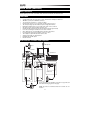
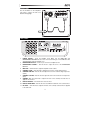
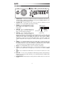
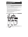
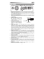
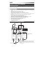
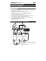
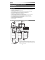
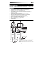
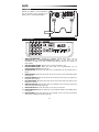
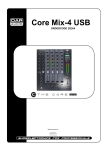
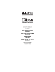
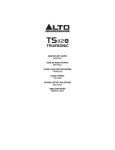
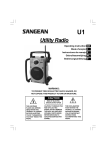
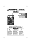
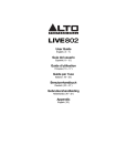
USER GUIDE
ENGLISH
GUÍA DEL USUARIO
ESPAÑOL
GUIDE D’UTILISATION
FRANÇAIS
GUIDA PER L'USO
ITALIANO
BENUTZERHANDBUCH
DEUTSCH
GEBRUIKERSHANDLEIDING
NEDERLANDS
USER GUIDE (ENGLISH)
BOX CONTENTS
Kick15 amplifier; power cable; User Guide; Safety Instructions & Warranty Information Booklet
FEATURES
•
•
•
•
•
•
•
•
•
•
•
•
•
•
•
4-channel mixer with stereo line inputs on each channel and an XLR input on Channel 1
400 Watts of peak power, 200 Watts continuous
15” low-frequency transducer, 1” compression driver
Custom-tuned electronic crossover provides superb frequency response
True bi-amped design provides dedicated power to high and low drivers
Built-in Alesis digital effects processor with reverb, delay, chorus, and more
256 effect presets: 16 effects with 16 variations each
Integrated folding steel kickstand provides the ideal monitoring angle instantly
Level, effects, and high & low EQ controls on all four channels
Stereo RCA input for connecting MP3 players and other audio devices
Footswitch input allows instant activation or bypass of effects
1/4" headphone output with dedicated volume control
Angled speaker baffle for optimized throw
Dual XLR and 1/4" Mix outputs
Ground Lift switch
QUICK SETUP / CONNECTION DIAGRAM
Microphone*
Power
Footswitch*
Synthesizer*
Loudspeaker*
Loudspeaker*
Subwoofer*
Power
Use the kickstand on the amplifier's rear panel to support the unit
at an ideal monitoring angle. See next page.
Power
*Note: Any items not mentioned under Box Contents are not
included.
2
KICKSTAND
Use the kickstand on the amplifier's
rear panel to support the unit at an
ideal monitoring angle.
TOP PANEL
6 6
6 6
4
3
7 7
8 8
5 5
7 7
8 8
5 5
9
10 11
2
1
1.
POWER SWITCH – Turns the amplifier on/off. Make sure the MAIN VOL and
HEADPHONES VOLUME knobs are set to "zero" before turning it on. The LED above this
switch illuminates when the amplifier is on.
2.
HEADPHONES OUTPUT – Connect your 1/4" stereo headphones here.
3.
HEADPHONES VOLUME – Turn this knob to adjust the level of the HEADPHONE
OUTPUT.
4.
MAIN VOL – Turn this knob to adjust the amplifier's main volume.
5.
CHANNEL LEVEL – Turn this knob to adjust the level of the corresponding channel.
6.
CHANNEL HIGH EQ – Turn this knob to adjust the level of the channel's high frequencies
(treble).
7.
CHANNEL LOW EQ – Turn this knob to adjust the level of the channel's low frequencies
(bass).
8.
CHANNEL FX – Turn this knob to adjust how much of the currently selected effect is
applied to the channel.
9.
EFFECT PRESETS – Turn this knob to select an effect.
10. EFFECT VARIATIONS – Turn this knob to select different variations of the selected effect.
11. FX LEVEL – Turn this knob to adjust how much of the currently selected effect is applied
to the entire mix.
3
REAR PANEL
1
2
3
3 5 4 9 8 8 8 8
7
3 6 10 9 8 8 8 8
3 11
1.
POWER INPUT – Connect the included power cable to this input and connect the other
end of the cable to a power source. Make sure the top panel's POWER SWITCH is set to
"off" when plugging and unplugging the cable.
2.
COOLING FAN – Keep the area in front of this vent clear from obstructions. The fan
behind the vent cools the amplifier, preventing overheating.
3.
MIX OUT – Use standard balanced XLR cables
or balanced 1/4" mono TRS cables to connect
these outputs to the inputs of your active
loudspeakers.
4.
SUB OUT – Use a standard balanced 1/4"
mono TRS cable to connect this output to the
input of an optional powered subwoofer.
5.
TRS connector
Tip
(left channel)
Sleeve
(ground)
Ring
(right channel)
LINK OUT – Use a standard unbalanced 1/4"
stereo TRS cable to connect this output to the
LINK IN of an optional second Kick amplifier (sold separately). When using this output, this
amplifier will be the "master"; it controls the audio, volume, etc. sent to the "slave" amplifier
connected to this output (each amplifier will output the same signal in parallel).
Alternatively, you may use a 1/4" stereo TRS splitter cable to connect this output to two
separate loudspeakers (left and right), two channels (left and right) of an external mixer,
etc.
6.
LINK IN – Use a standard unbalanced 1/4" stereo TRS cable to connect this input to the
LINK OUT of an optional second Kick amplifier (sold separately). When using this input,
this amplifier will be the "slave"; its levels will be controlled by the "master" amplifier
connected to this input (each amplifier will output a summed mono signal).
7.
MIC IN – Use a standard XLR cable to connect a microphone to this input.
8.
LINE IN – Use standard 1/4" TRS cables to connect line-level instruments or sound
sources to these inputs. When connecting a mono sound source, use only the "L/MONO"
input.
9.
AUX IN – Use a standard stereo RCA cable to connect a line-level sound source to these
inputs.
10. FOOT SW – You can connect a standard 1/4" TRS latching footswitch (sold separately) to
this input. A connected footswitch will allow you to activate/deactivate the amplifier's builtin effects processor.
11. GROUND SWITCH – Depressing this switch grounds the amplifier, which can reduce hum
or noise.
4
GUÍA DEL USUARIO (ESPAÑOL)
CONTENIDO DE LA CAJA
Amplificador Kick15; cable de alimentación; Guía del usuario; folleto de instrucciones de seguridad e
información sobre la garantía
CARACTERÍSTICAS
•
•
•
•
•
•
•
•
•
•
•
•
•
•
•
Mezclador de 4 canales con entradas de línea estéreo en cada canal y una entrada XLR en el canal 1
400 vatios de potencia pico, 200 vatios continuos
Transductor de baja frecuencia de 15 pulg. y driver de compresión de 1 pulg.
El crossover electrónico con afinación personalizada brinda una fantástica respuesta en frecuencia
El diseño de biamplificación verdadera brinda potencia dedicada para los drivers de frecuencias altas y
bajas
Procesador de efectos Alesis integrado con reverberación, retardo, coro y más
256 efectos predeterminados: 16 efectos con 16 variaciones cada uno
Soporte de acero plegable integrado que permite lograr instantáneamente el ángulo de monitoreo ideal
Controles de nivel, efectos y ecualización de frecuencias altas y bajas en los cuatro canales
Entrada RCA estéreo para conectar reproductores de MP3 y otros dispositivos de audio
Entrada para interruptor de pedal que permite la activación o puenteo instantáneo de los efectos
Salida para auriculares de 1/4 pulg. con control de volumen dedicado
Bafle del altavoz angulado para optimizar el alcance
Salidas de mezclador dobles XLR y de 1/4 pulg.
Interruptor de “levantamiento de tierra”
DIAGRAMA DE INSTALACIÓN Y CONEXIÓN RÁPIDA
Micrófono *
Alimentación
Interruptor
de pedal*
Sintetizador*
Altavoz*
Subwoofer*
Altavoz*
Alimentación
Use el soporte del panel trasero del amplificador para sostener la unidad en
un ángulo de monitoreo ideal. Consulte la página siguiente.
Alimentación
*Nota: No se incluye ningún elemento que no se mencione en Contenido de
la caja.
5
SOPORTE
Use el soporte del panel trasero del
amplificador para sostener la unidad en un
ángulo de monitoreo ideal.
PANEL SUPERIOR
6 6
6 6
4
3
7 7
8 8
5 5
7 7
8 8
5 5
9
10 11
2
1
1.
INTERRUPTOR DE ENCENDIDO – Se usa para encender y apagar el amplificador.
Asegúrese de que la perilla MAIN VOL (Volumen principal) y HEADPHONES VOLUME
(Volumen de auriculares) estén ajustadas a "cero" antes de encenderlo. Cuando el
amplificador está encendido, el LED de arriba de este interruptor se ilumina.
2.
SALIDA PARA AURICULARES – Conecte aquí sus auriculares estéreo de 1/4 pulg.
3.
VOLUMEN DE AURICULARES – Gire esta perilla para ajustar el volumen de la salida
HEADPHONES (Auriculares).
4.
VOLUMEN PRINCIPAL – Accione esta perilla para ajustar el volumen principal del
amplificador.
5.
NIVEL DE CANAL – Gire esta perilla para ajustar el nivel del canal correspondiente.
6.
ECUALIZACIÓN DE AGUDOS DEL CANAL – Gire esta perilla para ajustar el nivel de las
frecuencias altas (agudos) del canal.
7.
ECUALIZACIÓN DE GRAVES DEL CANAL – Gire esta perilla para ajustar el nivel de las
frecuencias bajas (graves) del canal.
8.
EFECTOS DEL CANAL – Gire esta perilla para ajustar la proporción del efecto
seleccionado actualmente que se aplica al canal.
9.
EFECTOS PRESELECCIONADOS – Gire esta perilla para seleccionar un efecto.
10. VARIACIONES DE EFECTOS – Gire esta perilla para seleccionar variaciones diferentes
del efecto seleccionado.
11. NIVEL DEL EFECTO – Gire esta perilla para ajustar la proporción del efecto seleccionado
actualmente que se aplica a la mezcla completa.
6
PANEL TRASERO
1
2
3
3 5 4 9 8 8 8 8
7
3 6 10 9 8 8 8 8
3 11
1.
ENTRADA DE ALIMENTACIÓN – Conecte a esta entrada el cable de alimentación
incluido y luego conecte el otro extremo del cable al suministro eléctrico. Asegúrese de
que el INTERRUPTOR POWER (Encendido) del panel superior esté en "off" (apagado)
cuando enchufe y desenchufe el cable.
2. VENTILADOR DE ENFRIAMIENTO – Mantenga el área frente a esta ventilación libre de
obstáculos. El ventilador que está detrás de la ventilación enfría el amplificador, evitando
el recalentamiento.
3. SALIDA DE MEZCLA – Use cables XLR
Conector TRS
balanceados o cables TRS mono de 1/4
pulg.
balanceados
estándar
para
conectar estas salidas a las entradas de
sus altavoces activos.
Manguito
Punta
4. SALIDA PARA SUBWOOFER – Use un
(tierra)
(canal izquierdo)
cable TRS mono de 1/4 pulg. balanceado
Nuca
estándar para conectar esta salida a la
(canal derecho)
entrada de un subwoofer alimentado
opcional.
5. SALIDA PARA ENLACE – Use un cable TRS estéreo de 1/4 pulg. no balanceado
estándar para conectar esta salida a la entrada LINK IN de un segundo amplificador Kick
opcional (que se vende por separado). Cuando usa esta salida, este amplificador será el
"maestro": controla el audio, volumen, etc. enviados al amplificador "esclavo" conectado a
esta salida (cada amplificador produce la misma señal de salida en paralelo). Como
alternativa, puede usar un cable divisor TRS estéreo de 1/4 pulg. para conectar esta
salida a dos altavoces (izquierdo y derecho) por separado, dos canales (izquierdo y
derecho) de un mezclador externo, etc.
6. ENTRADA PARA ENLACE – Use un cable TRS estéreo de 1/4 pulg. no balanceado
estándar para conectar esta salida a salida LINK IN de un segundo amplificador Kick
opcional (que se vende por separado). Cuando usa esta entrada, este amplificador será el
"esclavo": sus niveles serán controlados por el amplificador "maestro" conectado a esta
entrada (cada amplificador produce una señal mono sumada).
7. ENTRADA PARA MICRÓFONO – Use un cable XLR estándar para conectar un
micrófono a esta entrada.
8. ENTRADA PARA LÍNEA – Use cables TRS de 1/4 pulg. estándar para conectar a estas
entradas instrumentos o fuentes de sonido de nivel de línea. Cuando conecte una fuente
de sonido mono, use sólo la entrada "L/MONO" (Izquierda/Mono)
9. ENTRADA AUXILIAR – Use un cable RCA estéreo estándar para conectar una fuente de
nivel de línea a estas entradas.
10. INTERRUPTOR DE PEDAL – Es posible conectar a esta entrada un interruptor de pedal
con enganche TRS de 1/4 pulg. estándar (que se vende por separado. El interruptor de
pedal conectado le permite activar y desactivar el procesador de efectos integrado del
amplificador.
11. INTERRUPTOR DE TIERRA – Al presionar este interruptor se pone a tierra el
amplificador, lo que puede reducir el zumbido o el ruido.
7
GUIDE D’UTILISATION (FRANÇAIS)
CONTENU DE LA BOÎTE
Amplificateur Kick15; câble d'alimentation; guide d’utilisation; livret des consignes de sécurité et des
informations concernant la garantie.
CARACTÉRISTIQUES
•
•
•
•
•
•
•
•
•
•
•
•
•
•
•
Module de mixage 4 canaux avec entrées ligne stéréo sur chaque canal et une entrée XLR sur le
canal 1
400 watts de puissance de crête, 200 watts en continu
Transducteur de basses fréquences de 15 po, moteur de 1 po
Filtre électronique personnalisable procure une superbe réponse en fréquences
Conception bi-amplifiée véritable procure une puissance dédiée aux moteurs de hautes et basses
fréquences
Processeur d’effets numérique Alesis intégré avec Reverb, Delay, Chorus, et plus encore
256 effets prédéfinis : 16 effets offrant chacun 16 variantes
Support en acier pliant intégré offre l’angle parfait pour le monitorage
Niveaux, effets, et commandes d’égalisation hautes et basses fréquences sur les 4 canaux
Entrée RCA stéréo pour brancher un lecteur MP3 et d’autres appareils audio
Entrée pour pédale pour l’activation/dérivation d'effets instantanée
Sortie casque d'écoute ¼ po avec réglage du volume
Baffle incliné afin d’optimiser la diffusion
Sorties principales XLR doubles et ¼ po
Interrupteur de mise à la terre
INSTALLATION/SCHÉMA DE CONNEXION
Microphone*
Alimentation
Contacteur au pied*
Synthétiseur*
Caisson d’extrêmes
graves*
Hautparleur*
Hautparleur*
Alimentation
Utilisez le support sur le panneau arrière de l’amplificateur afin de maintenir
l'amplificateur dans l’angle approprié. Veuillez consulter la page suivante.
Alimentation
*Remarque : Les items non mentionnés dans la section Contenu de la
boîte ne sont pas inclus.
8
SUPPORT
Utilisez le support sur le panneau arrière de
l’amplificateur afin de maintenir l'amplificateur
dans l’angle approprié.
PANNEAU SUPÉRIEUR
6 6
6 6
4
3
7 7
8 8
5 5
7 7
8 8
5 5
9
10 11
1.
2
1
INTERRUPTEUR D’ALIMENTATION – Cet interrupteur permet de mettre l’amplificateur
sous et hors tension. Assurez-vous que les boutons du volume principal (MAIN MIX) et du
casque d’écoute (HEADPHONES) soient complètement fermés (« zéro ») avant de mettre
l’appareil sous tension. La DEL au-dessus de cet interrupteur s’allume lorsque
l’amplificateur est sous tension.
2. SORTIE CASQUE D’ÉCOUTE – Cette sortie permet de brancher un casque d’écoute
stéréo doté d’une fiche de ¼ po.
3. VOLUME CASQUE – Ce bouton ajuste les niveaux de la sortie du casque d'écoute
(HEADPHONES).
4. VOLUME PRINCIPAL – Ce bouton permet d’ajuster le volume principal de l’amplificateur.
5. POTENTIOMÈTRE DE CANAL – Ces potentiomètres permettent d'ajuster le niveau de
l’audio du canal correspondant.
6. POTENTIOMÈTRE D’ÉGALISATION (AIGUËS) – Ces potentiomètres permettent
d'ajuster le niveau des hautes fréquences du signal audio du canal correspondant.
7. POTENTIOMÈTRE D’ÉGALISATION (GRAVES) – Ces potentiomètres permettent
d'ajuster le niveau des basses fréquences du signal audio du canal correspondant.
8. POTENTIOMÈTRE DES EFFETS – Ces potentiomètres permettent d'ajuster la quantité
d’effet ajouter à l’audio du canal correspondant.
9. EFFETS PRÉDÉFINIS – Ce bouton permet de sélectionner un effet à ajouter.
10. VARIATIONS D’EFFET – Ce bouton permet de sélectionner une des variations de l’effet.
11. NIVEAU DES EFFETS – Ces potentiomètres permettent d'ajuster la quantité d’effet
ajouter au mix principal.
9
PANNEAU ARRIÈRE
1
2
3
3 5 4 9 8 8 8 8
7
3 6 10 9 8 8 8 8
3 11
1.
ENTRÉE D’ALIMENTATION – Branchez le câble d’alimentation inclus à cette entrée et
branchez l’autre extrémité à une source d’alimentation électrique. Assurez-vous que
l’interrupteur d’alimentation est réglé sur « Off » lorsque vous branchez/débranchez le
câble d’alimentation.
2. ORIFICE DE VENTILATION – Assurez-vous de maintenir cet orifice non obstrué en tout
temps. Le ventilateur se trouvant derrière permet de refroidir l’amplificateur afin qu’il ne
surchauffe pas.
3. SORTIE PRINCIPALE – Utilisez des câbles
Connecteur TRS
standards XLR symétriques ou ¼ po mono
TRS symétriques afin de brancher ces sorties
aux entrées des haut-parleurs.
4. SORTIE CAISSON D’EXTRÊMES GRAVES –
Pointe
Corps
Utilisez un câble ¼ po mono TRS symétrique
(canal gauche)
(masse)
standard afin de brancher cette sortie à un
Bague
caisson d’extrêmes graves facultatif.
(canal droit)
5. SORTIE PARALLÈLE – Utilisez un câble ¼ po
stéréo TRS asymétrique standard afin de brancher cette sortie à l’entrée parallèle d’un
second amplificateur Kick facultatif (non inclus). Lors de l’utilisation de cette sortie, cet
amplificateur devient maître, c.-à-d. qu'il commande l’audio, le volume, etc. acheminé à
l’autre amplificateur qui est branché à cette sortie (les deux amplificateurs projettent le
même signal en parallèle). En outre, vous pouvez utiliser un câble de répartition ¼ po
stéréo TRS afin de brancher cette sortie à deux haut-parleurs (gauche et droit), deux
canaux (gauche et droit) d’une console de mixage externe, etc.
6. ENTRÉE PARALLÈLE – Utilisez un câble ¼ po stéréo TRS asymétrique standard afin de
brancher cette entrée à la sortie parallèle d’un second amplificateur Kick facultatif (non
inclus). Lors de l’utilisation de cette entrée, cet amplificateur devient l’esclave, c.-à-d. que
l'audio, le volume, etc. sont commandés par l’autre amplificateur qui est branché à cette
entrée (chacun des amplificateurs projette une version mono du signal).
7. ENTRÉE MICROPHONE – Utilisez un câble XLR afin de brancher un microphone à cette
entrée.
8. ENTRÉE LIGNE – Utilisez des câbles ¼ po TRS standards pour brancher des
instruments à niveau ligne ou des sources audio à ces entrées. Lors de l’utilisation d’une
source audio mono, utilisez uniquement l'entrée « L/MONO ».)
9. ENTRÉE AUXILIAIRE – Utilisez un câble RCA stéréo standard pour brancher des
sources audio à niveau ligne à ces entrées.
10. ENTRÉE PÉDALE – Cette entrée permet de brancher un contacteur au pied TRS de ¼
po (non inclus). Un contacteur au pied permet d’activer/désactiver le processeur d’effets
intégré de l’amplificateur.
11. INTERRUPTEUR DE MISE À LA TERRE – Activer cet interrupteur permet de mettre à la
terre l’amplificateur et de réduire les bruits indésirables.
10
GUIDA PER L'USO (ITALIANO)
CONTENUTI DELLA CONFEZIONE
Amplificatore Kick15; cavo di alimentazione; Guida per l'uso; Istruzioni di sicurezza e garanzia
CARATTERISTICHE
•
•
•
•
•
•
•
•
•
•
•
•
•
•
•
Mixer a 4 canali con ingressi di linea stereo su ciascun canale e un ingresso XLR sul Canale 1
400 Watt potenza di picco, 200 Watt continui
Trasduttore di basse frequenze da 15", driver di compressione da 1"
Il crossover elettronico sintonizzato in maniera personalizzata offre un'eccezionale risposta di
frequenza
Il suo vero design a doppio amp offre una potenza dedicata per i driver alti e bassi
Processore di effetti digitali Alesis incorporato con reverb, delay, chorus e molto altro
256 preset effetti: 16 effetti con 16 varianti ciascuno
Il cavalletto pieghevole in acciaio integrato offre istantaneamente l'angolo di monitoraggio ideale
Comandi di livello, effetti ed EQ alti e bassi su tutti e quattro i comandi
Ingresso RCA stereo per il collegamento di lettori MP3 e di altri dispositivi audio
L'ingresso interruttore a pedale consente l'attivazione istantanea o l'aggiramento degli effetti
Uscita cuffie da 1/4" con controllo del volume dedicato
Deflettori angolati dell'altoparlante per un lancio ottimizzato
Doppie uscite XLR e da 1/4"
Interruttore di messa a terra
SCHEMA RAPIDO DI SETUP / DEI COLLEGAMENTI
Microfono*
Alimentazione
Interruttore a pedale*
Sintetizzatore*
Altoparlante*
Altoparlante*
Subwoofer*
Alimentazione
Servirsi del cavalletto posto a livello del pannello posteriore dell'amplificatore
per supportare l'apparecchio ad un'angolazione di monitoraggio ideale. Si
veda la pagina successiva.
Alimentazione
*Nota bene: qualsiasi articolo non menzionato nel paragrafo dedicato ai
Contenuti della confezione non è incluso.
11
CAVALLETTO
Servirsi del cavalletto posto a livello del
pannello posteriore dell'amplificatore
per supportare l'apparecchio ad
un'angolazione di monitoraggio ideale.
PANNELLO SUPERIORE
6 6
6 6
4
3
7 7
8 8
5 5
7 7
8 8
5 5
9
10 11
1.
2
1
INTERRUTTORE DI ALIMENTAZIONE (POWER) – Accende e spegne l'amplificatore.
Assicurarsi che le manopole MAIN VOL e CUFFIE siano impostate su "zero" prima di
accenderlo. Il LED al di sopra di questo interruttore si accende quando l'amplificatore è
acceso.
2. USCITA CUFFIE – Collegare a q uesto livello cuffie stereo da 1/4".
3. VOLUME CUFFIE – Girare questa manopola per regolare il livello dell'USCITA CUFFIE.
4. MAIN VOL – Girare questa manopola per regolare il volume principale dell'amplificatore.
5. LIVELLO CANALE – Girare questa manopola per regolare il livello del canale
corrispondente.
6. CHANNEL HIGH EQ (eq acuti canale) – Girare questa manopola per regolare il livello
delle frequenze alte del canale (acuti).
7. CHANNEL LOW EQ (eq bassi canale)– Girare questa manopola per regolare il livello
delle frequenze basse del canale (bassi).
8. CHANNEL FX (fx canale) – Girare questa manopola per regolare la quantità dell'effetto
selezionato da applicare al canale.
9. EFFECT PRESETS (preset effetti) – Girare questa manopola per selezionare un effetto.
10. EFFECT VARIATIONS (varianti effetti) – Girare questa manopola per selezionare
diverse varianti dell'effetto selezionato.
11. FX LEVEL (livello fx) – Girare questa manopola per regolare la quantità dell'effetto
selezionato da applicare all'intero mix.
12
PANNELLO POSTERIORE
1
2
3
3 5 4 9 8 8 8 8
7
3 6 10 9 8 8 8 8
3 11
1.
INGRESSO DI ALIMENTAZIONE – Collegare il cavo di alimentazione in dotazione a
questo ingresso, quindi collegare l’altro capo del cavo stesso ad una sorgente di
alimentazione. Assicurarsi che l'INTERRUTTORE DI ALIMENTAZIONE a livello del
pannello superiore sia su "off" al momento di collegare e scollegare il cavo.
2.
VENTOLA DI RAFFREDDAMENTO – Mantenere l'area di fronte a questa bocchetta
libera da ostacoli. La ventola dietro la bocchetta raffredda l'amplificatore, impedendone il
surriscaldamento.
3.
USCITA MIX – Servirsi di cavi standard
bilanciati XLR o cavi TRS mono bilanciati
da 1/4" per collegare queste uscite agli
ingressi degli altoparlanti.
4.
USCITA SUB – Servirsi di un cavo
standard TRS mono bilanciato da 1/4" per
collegare questa uscita all'ingresso di un
subwoofer opzionale.
Connettore TRS
Punta
(canale sinistro)
Manica
(terra)
Anello
(canale destro)
5.
USCITA LINK – Servirsi di un cavo standard TRS stereo bilanciato da 1/4" per collegare
questa uscita all'ingresso LINK IN di un secondo amplificatore Kick opzionale (venduto
separatamente). Quando si utilizza questa uscita, questo amplificatore sarà il "master":
controlla l'audio, il volume, ecc. inviati all'amplificatore "slave" collegato a questa uscita
(ciascun amplificatore emetterà lo stesso segnale in parallelo). Alternativamente, è
possibile utilizzare un cavo splitter stereo TRS da 1/4" per collegare questa uscita a due
altoparlanti distinti (sinistro e destro), due canali (sinistro e destro) di un mixer esterno,
ecc.
6.
INGRESSO LINK – Servirsi di un cavo standard TRS stereo non bilanciato da 1/4" per
collegare questo ingresso all'uscita LINK OUT di un secondo amplificatore Kick opzionale
(venduto separatamente). Quando si utilizza questo ingresso, questo amplificatore sarà lo
"slave": i suoi livelli saranno controllati dall'amplificatore "master" collegato a questo
ingresso (ciascun amplificatore emetterà un segnale mono sommato).
7.
INGRESSO MIC – Servirsi di un cavo standard XLR per collegare un microfono a questo
ingresso.
8.
LINE IN – Servirsi di cavi TRS standard da 1/4" per collegare strumenti a livello di linea o
fonti audio a questi ingressi. Al momento di collegare una fonte audio mono, servirsi
unicamente dell'ingresso "L/MONO".
9.
AUX IN – Servirsi di un cavo standard stereo RCA per collegare una fonte audio a livello
di linea a questi ingressi.
10. INTERRUTTORE A PEDALE – Collegare un interruttore a pedale standard TRS da 1/4"
(venduto separatamente) a questo ingresso. L'interruttore a pedale collegato consentirà di
attivare/disattivare il processore di effetti incorporato dell'amplificatore.
11. INTERRUTTORE DI MESSA A TERRA– La pressione di questo interruttore mette a terra
L'amplificatore, riducendo ronzii o rumore.
13
BENUTZERHANDBUCH (DEUTSCH)
LIEFERUMFANG
Kick15-Verstärker; Netzkabel; Benutzerhandbuch; Sicherheitshinweise und Garantieinformationen
FUNKTIONEN
•
•
•
•
•
•
•
•
•
•
•
•
•
•
•
4-Kanal Mixer mit Stereo-Line-Eingängen für jeden Kanal und einem XLR-Eingang auf Kanal 1
400 Watt Spitzenleistung, 200 Watt Dauerleistung
15" Tieftöner, 1" Hochtontreiber
Speziell abgestimmte, elektronische Frequenzweiche bietet hervorragenden Frequenzgang
Echtes Bi-Amp-Design bietet separate Leistung für Hoch- und Tieftöner
Integrierter Alesis-Digitaleffektprozessor mit Reverb, Delay, Chorus und mehr
256 Effekt-Presets: 16 Effekte mit jeweils 16 Variationen
Integrierte, einklappbare Stahlstütze zum sofortigen Anpassen des idealen Monitoring-Winkels
Pegel, Effekte und High & Low EQ-Regler auf allen vier Kanälen
Stereo-Cinch-Eingang für den Anschluss von MP3-Playern und anderen Audiogeräten
Footswitch-Eingang ermöglicht die sofortige Aktivierung oder Deaktivierung von Effekten
1/4" Kopfhörerausgang mit separatem Lautstärkeregler
Abgewinkelte Schallwand für optimales Abstrahlen
Duale XLR-Ausgänge und 1/4" Mix-Ausgänge
Ground Lift-Schalter
SCHNELLES EINRICHTEN / ANSCHLUSSDIAGRAMM
Mikrofon*
Stromversorgung
Fußschalter*
Synthesizer*
Lautsprecher*
Lautsprecher*
Stromversorgung
Subwoofer*
Verwenden Sie den Ständer auf der Verstärkerrückseite, um das Gerät
in einem idealen Monitoring-Winkel abzustützen. Siehe nächste Seite.
Stromversorgung
*Hinweis: Alle Artikel, die nicht im Abschnitt Lieferumfang erwähnt
werden, sind separat erhältlich.
14
STÄNDER
Verwenden Sie den Ständer auf der
Verstärkerrückseite, um das Gerät in
einem
idealen
Monitoring-Winkel
abzustützen.
OBERSEITE
6 6
6 6
4
3
7 7
8 8
5 5
7 7
8 8
5 5
9
10 11
1.
2
1
NETZSCHALTER - Schaltet das Gerät ein/aus. Stellen Sie sicher, dass die Regler für
GESAMTLAUTSTÄRKE und KOPFHÖRERLAUTSTÄRKE auf "Null" stehen, bevor Sie
das Gerät einschalten. Die LED oberhalb dieser Taste leuchtet auf, wenn der Verstärker
eingeschaltet ist.
2. KOPFHÖRERAUSGANG - Schließen Sie 1/4" Stereo-Kopfhörer an diesen Ausgang an.
3. KOPFHÖRERLAUTSTÄRKE - Mit diesem Regler stellen Sie die Lautstärke des
KOPFHÖRERAUSGANGS ein.
4. GESAMTLAUTSTÄRKE - Drehen Sie diesen Regler, um die Gesamtlautstärke des
Verstärkers anzupassen.
5. KANALPEGEL - Drehen Sie diesen Regler, um den Pegel des entsprechenden Kanals
einzustellen.
6. HÖHEN-EQ DES KANALS - Drehen Sie diesen Regler, um den Pegel der hohen
Frequenzen (Höhen) des Kanals einzustellen.
7. BASS-EQ DES KANALS - Drehen Sie diesen Regler, um den Pegel der tiefen
Frequenzen (Bass) des Kanals einzustellen.
8. KANAL-FX - Mit diesem Regler bestimmen Sie, wie hoch der Anteil des aktuell
ausgewählten Effekts für den Kanal sein soll.
9. EFFEKT-PRESETS - Drehen Sie diesen Regler, um einen Effekt zu wählen.
10. EFFEKTVARIATIONEN - Drehen Sie diesen Regler, um die verschiedenen Variationen
des gewählten Effekts auszuwählen.
11. FX-PEGEL - Mit diesem Regler bestimmen Sie, wie hoch der Anteil des aktuell
ausgewählten Effekts für den gesamten Mix sein soll.
15
RÜCKSEITE
1
2
3
3 5 4 9 8 8 8 8
7
3 6 10 9 8 8 8 8
3 11
1.
NETZEINGANG -Verbinden Sie das mitgelieferte Netzkabel mit diesem Eingang und das
andere Ende des Kabels mit einer Stromquelle. Achten Sie darauf, dass der
NETZSCHALTER auf der Oberseite auf "off" steht, wenn Sie das Kabel anschließen oder
abstecken.
2.
LÜFTER - Der Bereich vor dieser Lüftungsöffnung darf nie blockiert werden. Der
Ventilator hinter der Lüftungsöffnung kühlt den Verstärker und verhindert, dass das Gerät
überhitzt.
3.
MIX OUT - Verwenden Sie handelsübliche
XLR-Kabel (nicht im Lieferumfang enthalten),
um diese Buchsen mit den Eingängen Ihrer
Aktivlautsprecher zu verbinden.
4.
SUB-AUSGANG
Verwenden
Sie
handelsübliche, symmetrische 1/4" TRS-Kabel
(Mono), um diesen Ausgang mit dem Eingang
eines optionalen aktiven Subwoofers zu
verbinden.
TRS-Anschluss
Spitze
(Linker Kanal)
Manschette
Erde
Ring
(Rechter Kanal)
5.
LINK-OUT - Verwenden Sie ein handelsübliches, unsymmetrisches 1/4" TRS-Kabel, um
diesen Ausgang mit dem LINK-IN eines optionalen, zweiten Kick-Verstärkers zu verbinden
(separat erhältlich). Wenn Sie diesen Ausgang verwenden, arbeitet dieser Verstärker als
"Mastergerät": er steuert Audio, Lautstärke etc., die an den "Slave"-Verstärker gesendet
werden, der mit diesem Ausgang verbunden ist (jeder Verstärker gibt dasselbe Signal
parallel aus). Wahlweise können Sie ein 1/4" TRS-Splitter-Kabel verwenden, um diesen
Ausgang mit zwei getrennten Lautsprechern zu verbinden (links und rechts) bzw. mit zwei
Kanälen (links und rechts) eines externen Mixers etc.
6.
LINK-IN - Verwenden Sie ein handelsübliches, unsymmetrisches 1/4" TRS-Kabel, um
diesen Eingang mit dem LINK-OUT eines optionalen zweiten Kick-Verstärkers zu
verbinden (separat erhältlich). Wenn Sie diesen Eingang verwenden, arbeitet dieser
Verstärker als "Slave-Gerät": seine Pegel werden vom "Master"-Verstärker gesteuert, der
mit diesem Eingang verbunden ist (jeder Verstärker gibt ein summiertes Monosignal aus).
7.
MIC-EINGANG - Schließen Sie ein Mikrofon mit einem handelsüblichen XLR-Kabel an
diesen Eingang an.
8.
LINE IN - Verwenden Sie handelsübliche 1/4" TRS-Kabel, um Line-Level-Instrumente
oder Audioquellen an diese Eingänge anzuschließen. (Bei Anschluss einer MonoTonquelle verwenden Sie nur den "L/MONO"-Eingang.)
9.
AUX IN - Verwenden Sie ein handelsübliches Stereo-Cinch-Kabel, um eine Line-LevelSchallquelle an diese Eingänge anzuschließen.
10. FUSSSCHALTER - Sie können einen einrastenden Fußschalter (1/4" TRS, separat
erhältlich) an diesen Eingang anschließen. Mit einem angeschlossenen Fußschalter
können Sie den Effektprozessor aktivieren/deaktivieren, der in den Verstärker eingebaut
ist.
11. ERDUNGSSCHALTER - Das Betätigen dieses Schalters erdet den Verstärker, was
Brummgeräusche oder Rauschen reduzieren kann.
16
GEBRUIKERSHANDLEIDING (NEDERLANDS)
INHOUD VAN DE DOOS
Kick15-versterker; stroomkabel; Gebruikershandleiding; Veiligheidsvoorschriften en boekje met garantieinformatie
KENMERKEN
•
•
•
•
•
•
•
•
•
•
•
•
•
•
•
4-kanaalsmixer met stereo lijningangen op elk kanaal en een XLR-ingang op Kanaal 1
400 Watt piekvermogen, 200 Watt continu vermogen
Laagfrequente woofer van 15 inch, compressiedriver van 1 inch
Speciaal ingestelde elektronische crossover zorgt voor een uitstekende frequentierespons
Ontwerp met echte bi-amping (twee versterkers) voorziet de laag- en hoogfrequente luidsprekers
afzonderlijk van een signaal
Ingebouwde digitale effectprocessor van Alesis met echo, delay, chorus en meer
256 effect-presets: 16 effecten met elk 16 variaties
Geïntegreerde inklapbare stalen staander zorgt onmiddellijk voor de ideale monitorhoek
Niveau, effecten en EQ-bedieningsknoppen voor hoge en lage tonen op alle vier kanalen
Stereo RCA-ingang om mp3-spelers en andere audiobronnen te verbinden
Ingang voor voetschakelaar voor onmiddellijke activering of bypass van effecten
Koptelefoonuitgang van 1/4 inch met aparte volumeregeling
Onder hoek geplaatste luidspreker voor optimale spreiding
Dubbele Mix-uitgangen van type XLR en 1/4"
Ground lift-schakelaar
SNELLE OPSTELLING / VERBINDINGSDIAGRAM
Microfoon*
Voeding
Voetschakelaar*
Synthesizer*
Luidspreker*
Luidspreker*
Subwoofer*
Voeding
Gebruik de staander op het achterpaneel van de versterker om het apparaat
in een ideale hoek voor monitoring te plaatsen. Zie de volgende pagina.
Voeding
*Opmerking: * Artikelen die niet vermeld zijn in Inhoud van de doos zijn niet
meegeleverd.
17
STAANDER
Gebruik de staander op het achterpaneel
van de versterker om het apparaat in een
ideale hoek voor monitoring te plaatsen.
BOVENPANEEL
6 6
6 6
4
3
7 7
8 8
5 5
7 7
8 8
5 5
9
10 11
1.
2
1
AAN/UIT-SCHAKELAAR: schakelt de versterker aan/uit. Zorg ervoor dat de
HOOFDVOLUME- en KOPTELEFOONVOLUME-knoppen op "nul" staan voor het
inschakelen. De LED boven deze schakelaar gaat branden wanneer de versterker is
ingeschakeld.
2. KOPTELEFOONUITGANG: Sluit hierop uw 1/4"-stereokoptelefoon aan.
3. KOPTELEFOONVOLUME: Draai aan deze knop om het geluidsniveau van de
KOPTELEFOONUITGANG aan te passen.
4. HOOFDVOLUME: Draai aan deze knop om het hoofdvolume van de versterker aan te
passen.
5. KANAALNIVEAU: Draai aan deze knop om het niveau van het overeenkomstige kanaal
aan te passen.
6. EQ HOOG KANAAL: Draai aan deze knop om het niveau van de hoge tonen (treble) van
het kanaal aan te passen.
7. EQ LAAG KANAAL: Draai aan deze knop om het niveau van de lage tonen (bas) van het
kanaal aan te passen.
8. KANAALEFFECTEN: Draai aan deze knop om te bepalen hoeveel van het geselecteerde
effect aan het kanaal wordt toegevoegd.
9. EFFECTPRESETS: Draai aan deze knop om een effect te selecteren.
10. EFFECTVARIATIES: Draai aan deze knop om verschillende variaties van hetzelfde effect
te selecteren.
11. EFFECTNIVEAU: Draai aan deze knop om te bepalen hoeveel van het geselecteerde
effect aan de volledige mix wordt toegevoegd.
18
ACHTERPANEEL
1
2
3
3 5 4 9 8 8 8 8
7
3 6 10 9 8 8 8 8
3 11
1.
STROOMINGANG: sluit de meegeleverde stroomkabel aan op deze ingang en sluit het
andere uiteinde van de kabel aan op een stroombron. Zorg ervoor dat de AAN/UITSCHAKELAAR op het bovenpaneel op "uit" staat bij het aansluiten en loskoppelen van de
kabel.
2.
KOELVENTILATOR: Hou de ruimte voor deze opening vrij van andere voorwerpen. De
ventilator achter deze opening koelt de versterker af en voorkomt oververhitting.
3.
MIX OUT: Gebruik standaard gebalanceerde
XLR-kabels of gebalanceerde 1/4" mono TRSkabels om deze uitgangen aan te sluiten op de
ingangen van uw actieve luidsprekers.
4.
SUB
OUT:
Gebruik
een
standaard
gebalanceerde 1/4" mono TRS-kabel om deze
uitgang aan te sluiten op de ingang van een
optionele versterkte subwoofer.
TRS-connector
Tip
(linkerkanaal)
Mantel
(aarding)
Ring
(rechterkanaal)
5.
LINK
OUT:
Gebruik
een
standaard
ongebalanceerde 1/4" stereo TRS-kabel om deze uitgang aan te sluiten op de LINK IN
van een optionele tweede Kick-versterker (afzonderlijk te koop). Bij het gebruik van deze
uitgang wordt deze versterker de 'master'; hij controleert de audio, het volume, enz. die
worden verstuurd naar de 'slave'-versterker die op deze uitgang is aangesloten (elke
versterker produceert parallel hetzelfde signaal). Anderzijds kunt ook een 1/4" stereo TRSsplitterkabel gebruiken om deze uitgang aan te sluiten op twee afzonderlijke luidsprekers
(links en rechts), twee kanalen (links en rechts) van een externe mixer, enz.
6.
LINK IN: Gebruik een standaard ongebalanceerde 1/4" stereo TRS-kabel om deze ingang
aan te sluiten op de LINK OUT van een optionele tweede Kick-versterker (afzonderlijk te
koop). Bij het gebruik van deze uitgang wordt deze versterker de 'slave'; zijn instellingen
worden gecontroleerd door de 'master'-versterker die op deze ingang is aangesloten (elke
versterker produceert een opgeteld monosignaal).
7.
MIC IN: Gebruik een standaard XLR-kabel om een microfoon op deze uitgang aan te
sluiten.
8.
LIJNINGANG: Gebruik standaard 1/4" TRS-kabels om instrumenten of geluidsbronnen op
lijnniveau op deze ingangen aan te sluiten. Gebruik bij het aansluiten op een
monogeluidsbron enkel de ingang "L/MONO".
9.
AUX IN: Gebruik een standaard stereo RCA-kabel om een geluidsbron op lijnniveau op
deze ingangen aan te sluiten.
10. VOETSCH: Op deze ingang kunt u een standaard 1/4" TRS-voetschakelaar met
vergrendeling (afzonderlijk verkocht) aansluiten. Met een aangesloten voetschakelaar kunt
u de ingebouwde effecten van de versterker activeren of deactiveren.
11. AARDINGSSCHAKELAAR: Druk deze knop in om de versterker te aarden, wat brom of
ruis kan verminderen.
19
SPECIFICATIONS
Output Power:
400 W Peak (270 W LF @ 8 Ω + 130 W HF @ 8 Ω)
200 W Continuous RMS (135 W LF @ 8 Ω + 65 W HF@ 8 Ω)
Headphone output: 105 mW, 75 kΩ
Crossover:
3 kHz
Frequency Response:
65 Hz – 19 kHz (+ 3 dB)
Low Frequency:
15" (381 mm) woofer, 2" (51 mm) voice coil
High Frequency:
Compression driver, 1" (25 mm)
Input Level:
XLR (Mic, Ch. 1): -10 dBu max
1/4": -10 dBV nominal, 0 dBV max
RCA: -10 dBV nominal, 0 dBV max
Channel Gain:
-∞ to +10 dB (Ch. 1 to Ch. 4)
Output Gain:
-∞ to +10 dB (main mix output)
Maximum Available Gain:
XLR (Mic, Ch. 1): 40 dB
Line: 30 dB
(including fixed preamp gain)
Connectors:
Inputs:
One XLR
Eight 1/4" TRS (4 stereo pairs)
One RCA stereo pair
One 1/4" TRS link
One 1/4" TS footswitch
Outputs: Two XLR (L/R)
Two 1/4" (L/R)
One 1/4" TRS subwoofer
One 1/4" TRS link
One 1/4" TRS headphone
Effects:
Alesis DSP, 16 effects, 16 variations per effect
Vocal: Vocal 1, Vocal 2
Reverb: Large Hall, Small Hall, Large Room, Small Room, Plate Reverb,
Tape Reverb, Spring Reverb
Delay: Mono, Stereo
Modulation: Flanger, Chorus
Combination: Reverb+Delay, Reverb+Flanger, Reverb+Chorus
Power supply:
100 VAC (-10%/+15%), 120 VAC (-10%/+15%),
or 240 VAC (-10%/+15%); 50/60 Hz; IEC connector
Inrush current at initial switch-on: 1.01 A
Inrush current after power supply interruption: 1.81 A
Enclosure:
Composite wood; perforated steel grille; 2 side handles, 1 top handle
Dimensions (H x W x D):
21.5" x 19" x 14.6" (546 mm x 483 mm x 371 mm)
Weight:
Net (unit): 43.6 lbs.; 19.8 kg
Gross (shipping): 50.2 lbs.; 22.8 kg
altoprofessional.com
MANUAL VERSION 1.0