1
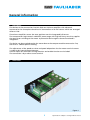
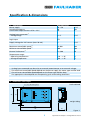
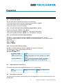
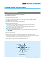
Servo Amplifier
2-Quadrant PWM for Brushless DC-Servomotors
Series BLD 5018
Operating Instructions
c om
w. fau
w
w
l
h
er.
b
a
Miniature Drive Systems
Micro Drives
DC-Micromotors
Precision Gearheads
Servo Components
Drive Electronics
Surf to the following Internet
address and you will find the
latest edition of the instruction
manual on-line :
www.minimotor.ch/uk/pr/
For direct Download:
http://www.minimotor.ch/minicatalog/pdf/DriveCircuits/Manuals/IM_e_BLD_5018.pdf
Index
Chapter
1.
Description
page
2
2.
Illustration
2
3.
Specification
3
4.
Dimensions and weight
3
5.
5.1
Safety notes
Connection informations
4
4
6.
6.1
6.2
6.3
6.3.1
6.3.2
6.3.3
6.4
6.5
Preparing
Control input for turning direction
Control input for disable
Set value for speed
Set value with the internal trimming potentiometer
Set value with an external potentiometer
Set value with external voltage
Adjusting motor current
Shut down at overheat
5
5
5
6
6
6
6
6
6
7.
7.1
7.2
7.3
Considerations and procedure
Considerations to put the device into operation
Considerations to power supply
Procedure for calculating the required minimum supply voltage
7
7
8
8
8.
Assembly note
9
1
General information
1.
Description
The devices of the construction line BLD 5018 are 2Q Servo amplifier with electronic
commutation for three-phase brushless DC-Servomotors with Hall sensors which are arranged
offset at 120°.
These Servo Amplifiers assess the rotor position over the integrated hallsensors.
The commutation logic controls a MOSFET power stage with high efficiency rate that supplies
the specific part winding of the motor. A protection device against thermal overload is
integrated.
The device can be attached nearby the motor due to the compact module construction line,
the result is a better power tracking.
The adjustment of the speed set value and speed adaptation also for motor nominal current
is to be set by internal potentiometers.
Control inputs for the motor turning direction and enable function are included.
The connection is by a robust screw terminal.
2.
Illustration
Figure 1
2
Specifications subject to change without notice
Specification & dimensions
3. Specification
Power supply
Switching frequency
Continuous output current @ TA = 22°C
BLD 5018-SC2P
20 ÷ 50
20
18
V DC
kHz
A
Analog input command: 1)
– Voltage range
0÷5
V DC
Logic input
TTL
Supply voltage for Hall sensors (max. 20 mA)
5
V DC
Maximum controllable speed 2)
Minimum controllable speed 3)
12 000
800
rpm
rpm
External inductance 4)
0 ÷ 300
µH
Temperature range:
– Operating temperature
– Storage temperature
–10 ... + 45
–40 ... + 85
°C
°C
1)
Analog input command may be set by an external potentiometer or an external voltage.
The maximum controllable speed depends on the power supply, the motor type and the load.
The minimum controllable speed depends on the motor type and the load.
The appropriate value depends on the operating cycle and working conditions.
2)
3)
4)
4.
Dimensions and weight
Scale reduced
4 x ø 4,5 Mounting hole
1
1
2
F1
4
3
5
4
6
F2
5
7
5
2
64
3
90
X2
X1
1
1
8
9
F3
9
weight 360 g
5
165
40
170
Figure 2
3
Specifications subject to change without notice
Safety notes and connection informations
5.
Safety notes
Operating voltages exceeding the specified values or reverse-connection will destroy the
devices.
Unauthorised opening and improper repairs will put the user in danger.
If the module is brought from a cold environment into the operating environment, there
can be condensation. Wait until the module has reached the right temperature and is
absolutely dry before it is put into operation.
5.1 Connection informations
9-pin connector (signals)
Plug loading
Nr. Printing Description
1
H1
Hall sensor 1
2
H2
Hall sensor 2
3
H3
Hall sensor 3
4
UH
Supply voltage for Hall sensors
5
GND Ground connection for Hall sensors
6
Dis
Control Input disable (free curcuit)
7
Rev
Control Input reverse (turning direction)
8
GND Ground for control and set value input
9
Spd
Set value input for speed
5-pol connectors (power)
Nr. Printing Description
1
Ub
Supply voltage +
2
L1
Motorwinding 1
3
L2
Motorwinding 2
4
L3
Motorwinding 3
5
GND Ground for supply voltage
4
Specifications subject to change without notice
Preparing
6.
Preparing
6.1 Control input for turning direction (Rev)
The control input „Rev“is for changing the turning direction and can be controlled as following:
With external switch
Open collector transistor
With TTL/CMOS module
"Rev"not connected or high level
"Rev"connected to GND 8 or low level
Turning clockwise
Turning counter clockwise
Direction of rotation can be changed only when motor stopped.
6.2 Control input for disable (Dis)
The control input „Dis“is for disabling the unit and can be controlled as following:
With external switch
Open collector transistor
With TTL/CMOS module
"Dis"not connected or high level
"Dis"connected to GND 8 or low level
Motor is turning
Motor does not turn
Important notice:
For stopping the motor it is not advisable to make the set value to 0, but support this through
disable. Some motors could otherwise drift shortly. This happens through the integral part of
those controllers.
5
Specifications subject to change without notice
Preparing
6.3
Set value for speed
The set value for the speed can be preset like following:
6.3.1 By the means of the internal trimming potentiometer „speed“
6.3.2 By the means of an external potentiometer
6.3.3 By the means of external voltage
6.3.1 Set value with the internal trimming potentiometer „speed“
Short circuit between „GND 8“ and „Spd 9“.
Turn trimming potentiometer „Speed“ to -: The speed is decreasing
Turn trimming potentiometer „Speed“ to +: The speed is increasing
6.3.2 Set value with an external potentiometer
The built in trimming potentiometer „Speed“ has to be positioned on – for this.
An external potentiometer with 10K is required. The potentiometer is to be connected as
following:
Start: at „UH4“
End: at „GND 8“
wiper: at „Spd 9“
6.3.3 Set value with external voltage
The built in trimming potentiometer „speed“ has to be positioned on –
The external set value is connected as following:
Set value GND to „GND 8“
Set value at „Spd9“
Set value voltage
= 0V
> 0,1V to about 4,5V
> 4,5V to about 5V
6.4
Speed
Stop
Speed according to set value voltage with speed
control
Motor turns with maximum speed, according
the supply voltage and is out of regulating
range
Adjusting motor current (Imax)
The current preset by trimming potentiometer „Imax.“ as following:
Type
BLD 5018
6.5
Maximum left position
6 -7 A
Maximum right position
> 18A
Shut down at overheat
The controller shuts down automatically when the temperature at the inside of the heat sink
exceeds 80°C .
6
Specifications subject to change without notice
Considerations and procedure
7.
Considerations and procedure
7.1 Considerations to put the device into operation
Please follow the sequence!
1. Connect Motor to L1, L2 and L3
2. Connect Hall sensors H1, H2, H3 as well as Hall sensor supply to „UH4“ and GND
to „GND 5“ from Hall sensors.
3. Connect control inputs according to requirements.
4. Preadjust potentiometer (270°)·
At internal set value of the speed turn trimming potentiometer speed to –
(short circuit between „GND 8“ and „Spd“)
At external set value of the speed turn trimming potentiometer speed to –
and connect 0V to „Spd 9“ against „GND 8“.
Turn trimming potentiometer Imax. to +
Preadjust trimming potentiometer nmax. according to required maximum speed:
+: max. speed
-: min. speed
5. Connect supply voltage
6. Increase speed set value by Trimming potentiometer or by external set value.
As long as the controller is in the active regulating range, the speed can be adjusted by
trimming potentiometer speed at a constant external set value.
7. Adjust maximum current with trimming potentiometer Imax.
~4-5A
~6A
~20-22A
~16-17A
~8A
~10A
~12-13A
Potentiometer Imax.
7
Specifications subject to change without notice
Considerations and procedure
7.2
Considerations to power supply
Output voltage:
>12V und <Vcc with a residual voltage of <5%
Higher voltages will destroy device.
Output current:
Corresponding to the required torque and possible reserves for acceleration.
7.3
Procedure for calculating the required minimum supply voltage:
Default:
Operating moment:
Operating speed:
Rated voltage of motor:
Idling speed with UN:
Characteristic curve slope:
MB
nB
UN
n0
∆n
∆M
Result:
Vcc =
[mNm]
[min -1 ]
[V]
[min -1 ]
[min -1 mNm]
UN
n0
8
· ( nB +
∆n
∆M
· MB ) + 4V
Specifications subject to change without notice
Assembly note
8.
Assembly note
Optimum heat dissipation is achieved by mounting the BLD 5018 module on a cooling
surface and by the use of a thermal conduction paste.
For longer distances between the motor and the control (>30cm), shielded cables
should be used for the sensor cable and the motor cable.
9
Specifications subject to change without notice
The FAULHABER Group:
DR. FRITZ FAULHABER
GMBH & CO. KG
Daimlerstraße 23
71101 Schönaich · Germany
Tel.: +49 (0)7031/638-0
Fax: +49 (0)7031/638-100
Email: [email protected]
www.faulhaber.de
MINIMOTOR SA
6980 Croglio · Switzerland
Tel.: +41 (0)91 611 31 00
Fax: +41 (0)91 611 31 10
Email: [email protected]
www.minimotor.ch
MicroMo Electronics, Inc.
14881 Evergreen Avenue
Clearwater · FL 33762-3008 · USA
Phone: +1 (727) 572-0131
Fax: +1 (727) 573-5918
Toll-Free: (800) 807-9166
Email: [email protected]
www.micromo.com
© MINIMOTOR SA, Switzerland
MA15001, english, 1. issue, 11.10.2001


![Final Report - [Almost] Daily Photos](http://vs1.manualzilla.com/store/data/005658230_1-ad9be13b69bd4f2e15f58148160b0f22-150x150.png)