1
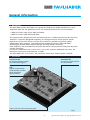
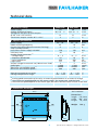
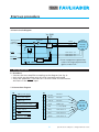
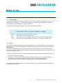
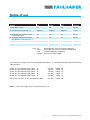
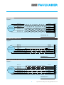
Motion Controller
2-Quadrant PWM for Brushless DC-Servomotors
Series BLD 5604
Series BLD 5608
Operating Instructions
c om
ww
w. fau
l
h
er.
b
a
Miniature Drive Systems
Micro Drives
DC-Micromotors
Precision Gearheads
Servo Components
Drive Electronics
Surf to the following Internet
address and you will find the
latest edition of the instruction
manual on-line:
www.minimotor.ch/uk/pr/
For direct Download:
http://www.minimotor.ch/minicatalog/pdf/DriveCircuits/Manuals/IM_e_BLD_5604_5608.pdf
Index
General information
1.
Description
2.
Illustration
Technical data
3.
Maximum ratings
4.
Specific characteristics
5.
Dimensions and weight
General characteristics
6.1
Speed command
6.2
Speed regulator, type PI
6.3
Direction
6.4
Brake
6.5
Protection against motor stall
6.6
Excess -temperature protection
6.7
Basic circuit diagram
Start-up procedure
7.1
Procedure
7.2
Connection diagram
Notice of use
8.1
Power supply
8.2
Wiring
General information
1. Description
The BLD 5604 and the BLD 5608 are 2-quadrant PWM (Pulse-Width Modulation) servo
amplifiers ideal for the speed control of our three-phase brushless DC-servomotors:
• 5604 for motor types 1628, 2036 and 2444;
• 5608 for motor types 3056 and 3564.
The commutation sequence of the servomotor phases is made electronically by the servo
amplifier. A specially designed frequency-to-voltage converter allows precise speed
regulation via the Hall sensors without the need of an encoder (regulator type PI,
proportional plus integral). The combination of MOSFET power stage and PWM
technologies enables both compact design and high power efficiency.
Both amplifiers are provided with thermal and motor stall protection and pulse-by-pulse
current limitation.
For the BLD 5604-SH2P the current limit is set to 4A; without additional heat sink, the
maximum continuous output power is 150W.
The BLD 5608-SH2P is set to 8A ; the maximum continuous output power is 250 W.
2. Illustration
Connector X2
to connect power supply
and command signal
Connector X1
to connect the brushless
DC-servomotor
LED
signals a protection
intervention and the
servo amplifier
desactivation
Heat sink with four mounting slots
Fig. 1
2
Specifications subject to change without notice
Technical data
5604-SH2P
3.
3. Maximum ratings
Power supply
Analog and logical inputs
Voltage for the pull-up fault output
(8 mA max. sink current)
Continuous output current @ TA = 22°C
60
–0,3 to
5608-SH2P
60
–0,3 to
5
12
3
4. Specific characteristics
Power supply
PWM switching frequency
Current limit (pulse-by-pulse current limiting)
Total standby current,
Hall-effect sensors supply included
Efficiency max.
Analog speed command: (1)
- voltage range
- frequency bandwidth
- input impedance
Logic inputs
Output voltage for external use (100 mA max. load)
Speed gain
Maximum controllable speed (2)
Minimum controllable speed (3)
Operating temperature range
Storage temperature range
V DC
V DC
5
12
5
V DC
A
10 ÷ 56
25
4
10 ÷ 56
25
8
120
95
120
95
0 ÷ 5
10
460
TTL
5
12 000
60 000
800
0 ÷ 5
10
460
TTL
5
6 000
30 000
800
0 ... + 70
–20 ... +120
0 ... + 70
–20 ... +120
V DC
kHz
A
mA
%
V DC
Hz
kΩ
V DC
V DC
rpm/V
rpm
rpm
˚C
˚C
1)
analog speed command may be set by an external potentiometer or an external voltage
the maximum speed depends on the power supply, the motor type and the load
3) the minimum speed depends on the motor type, the inertia and the viscous friction of the load
2)
5. Dimensions and weight
Scale reduced
114,3
4
Dimensions
length 114,3 mm
width 100 mm
height
28,7 mm
1
1
8
X2
2
X1
3
100
Weight
200 g
4
C
5
6
7
LED
1
8
8
5
6
28,7
102,3
3
Fig. 2
Specifications subject to change without notice
General characteristics
6.
General characteristics
6.1 Analog speed command
The speed command is given by an external voltage from 0 to 5V or by a potentiometer
connected directly to the servo amplifier (see fig. 4).
The total potentiometer resistance must be between 10 kΩ and 47 kΩ.
Furthermore, a PWM signal with a maximum amplitude of 5V and a minimum frequency of
1 kHz can be used as a speed command.
6.2 Speed regulator, type PI
A Proportional plus Integral (PI) speed regulator controls a brushless DC-servomotor with
no steady-state error (step input command).
6.3 Direction
The direction of rotation is changed using either a high or low input signal (TTL compatible).
When a high input signal is given or the input is unconnected (internal pull-up resistance),
the motor turns in the clockwise direction (CW).
When a low input command is given or the input is connected to GND, the motor turns in
the counterclockwise direction (CCW).
6.4 Brake
This feature allows the motor to brake dynamically by applying a low input signal to the
BRAKE input.
The braking torque is proportional to the speed: at standstill, there is no torque applied to
the motor. This logical input also has the function to reset the servo amplifier when an
error message is given via the red LED.
We recommend using this feature at speeds below 10 000 rpm.
6.5 Protection against motor stall
This protection is a special feature to preserve the motor in case of mechanical blocking or
motor stall. The servo amplifier will be disactivated after few seconds, when the motor is
powered, it does not turn.
At the same time this intervention will be signalled by the red LED and with the activation
of the Fault Output (open-collector). To reset and reactivate the servo amplifier it is
necessary to turn the BRAKE input low and then high.
6.6 Excess temperature protection
The servo amplifier automatically shuts off if the heat sink temperature exceeds +75 °C.
When the temperature is below +70 °C the servo amplifier can be restarted with the BRAKE input.
4
Specifications subject to change without notice
Start-up procedure
6.7 Basic circuit diagram
Vm GND
Speed
amplifier
Analog speed
command
Fault output
+
Phase
Phase
Phase
BLM
Driver
–
*
A
B
C
Brushless
DC-Servomotor
1628, 2036,
2444, 3056,
3564
+ 5V
Hall sensor A
Hall sensor B
Hall sensor C
Brake
Direction
CW/CCW
+5V
GND
F/V
converter
Logic
* Excess temperature protection,
current limiting and protection
against motor stall.
7. Start-up procedure
7.1 Procedure
• Connect the servo amplifier according to the diagram (see fig. 4)
• Only switch on the power once all wires have been connected
• Verify the operation; if the red LED is on then check the connections
and reset via the BRAKE input.
7.2 Connection diagram
X2
X1
1
GND power supply
2
Vm power supply
3
4
5
6
7
8
GND Logic
Analog speed comm.
+ 5 V (output)
Fault output
Brake
Direction (CW/CCW)
8
7
6
5
4
3
2
1
Brown
Phase A
Orange
Phase B
Yellow
Phase C
Black
GND Logic
Red
+ 5 V (output)
Grey
Hall sensor C
Blue
Hall sensor B
Green
Hall sensor A
Brushless
DC-Servomotor
1628, 2036,
5
2444, 3056,
3564
Specifications subject to change without notice
Notice of use
8. Notice of use
8.1
Power supply
Any unstabilized power supply voltage within the servo amplifier range (10V ≤ Vm ≤ 56 V)
may be used, although it is advisable to keep this voltage as low as possible in order to
minimize the electromagnetic interferences (EMI).
Thus the optimum power supply is given by the following relation:
Vm [V] ≈ 5 [V] + R [Ω] · Imax [A] + kE [V/rpm] · nmax [rpm]
with R :
kE :
Imax :
nmax :
terminal resistance of the motor phases;
back-EMF constant of the motor;
maximum current reached by the motor in your specific application;
maximum speed reached by the motor in your specific application.
8.2 Wiring
A well known disadvantage of pulse-width modulation, is the large amount of interferences
generated. This has two consequences, namely perturbations to the environment and self
perturbations.
The EMI are generated in the motor power leads and induced in the Hall-effect sensor
wires. The smooth running of the motor is therefore perturbed and even in some cases, the
motor will not run at all.
In order to reduce the effect of these perturbations, there are some basic rules to follow:
• use wires as short as possible;
• avoid to run signal wires (logical and analog command, Hall-effect sensors signals) in
close proximity to power lead wires (power supply and servomotor phases);
• connect shielded wires to ground at one end only to avoid ground loops.
A special care should be given to the motor connection. The following table summarizes
the different solutions:
6
Specifications subject to change without notice
Notice of use
Action
To
From
Self
Length
1. No special care
no
no
no
0.3 m
2. Twisted wires (see fig. 5)
slightly
slightly
slightly
1.0 m
3. Shielded Hall-effect sensor
wires (see fig. 6)
4. Shielded Hall-effect sensor
and phases wires (see fig. 7)
no
yes
yes
5.0 m
yes
yes
yes
5.0 m
with To:
From:
Self:
Length:
perturbations to environment reduced
perturbations from environment reduced
self perturbations reduced
maximum cable length
In case of wires longer than the standard product (0,3 m) it is recommended to use the following
cable sections:
Phase, DC-Servomotor type 1628 ... B:
Phase, DC-Servomotor type 2036 ... B:
Phase, DC-Servomotor type 2444 ... B:
Phase, DC-Servomotor type 3056 ... B:
Phase, DC-Servomotor type 3564 ... B:
0,5 mm2
1,0 mm2
1,0 mm2
1,5 mm2
1,5 mm2
Hall-effect sensors, all DC-Servomotor types:
0,5 mm2 / AWG 20
/ AWG
/ AWG
/ AWG
/ AWG
/ AWG
20
18
18
16
16
Note: If wires are longer than 5 m please consult us.
7
Specifications subject to change without notice
Twisted wires
Figure 5
Brushless
DC-Servomotor
Brown
Orange
Yellow
Black
Red
Grey
Blue
Green
Phase A
Phase B
Phase C
GND Logic
+ VCC
Hall sensor C
Hall sensor B
Hall sensor A
8
7
6
5
4
3
2
1
Connector X1
Shielded Hall sensor wires
Figure 6
Brushless
DC-Servomotor
Brown
Orange
Yellow
Black
Red
Grey
Blue
Green
Phase A
Phase B
Phase C
GND logic
+VCC
Hall sensor C
Hall sensor B
Hall sensor A
8
7
6
5
4
3
2
1
Connector X1
Shielded phase and Hall sensor wires
Figure 7
Brushless
DC-Servomotor
Phase A
Phase B
Phase C
GND logic
+ VCC
Hall sensor C
Hall sensor B
Hall sensor A
Brown
Orange
Yellow
Black
Red
Grey
Blue
Green
8
7
6
5
4
3
2
1
Connector X1
8
Specifications subject to change without notice
The FAULHABER Group:
DR. FRITZ FAULHABER
GMBH & CO. KG
Daimlerstraße 23
71101 Schönaich · Germany
Tel.: +49 (0)7031/638-0
Fax: +49 (0)7031/638-100
Email: [email protected]
www.faulhaber.de
MINIMOTOR SA
6980 Croglio · Switzerland
Tel.: +41 (0)91 611 31 00
Fax: +41 (0)91 611 31 10
Email: [email protected]
www.minimotor.ch
MicroMo Electronics, Inc.
14881 Evergreen Avenue
Clearwater · FL 33762-3008 · USA
Phone: +1 (727) 572-0131
Fax: +1 (727) 573-5918
Toll-Free: (800) 807-9166
Email: [email protected]
www.micromo.com
©MINIMOTOR SA
Edition 29.05.2000
![Final Report - [Almost] Daily Photos](http://vs1.manualzilla.com/store/data/005658230_1-ad9be13b69bd4f2e15f58148160b0f22-150x150.png)