1
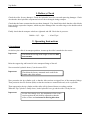
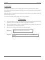
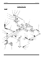
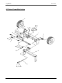
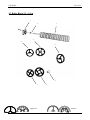
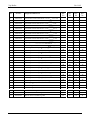
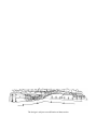
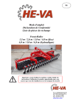
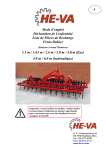
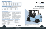
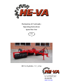
Declaration of Conformity
Operating Instructions
Spare Part List
UK
HE-VA Vip-Roller 3.3
4.5 m
N. A. Christensensvej 34
DK-7900 Nykøbing Mors
Tel: 9772 4288
Fax:9772 2112
www.he-va.com
Vip-Roller
24-01-03
Contents
Declaration of Conformity .......................................................................................... 4
1.
Delivery Check .............................................................................................................. 5
2.
Operating Instructions
2.1. .. Attachment ........................................................................................................... 5
2.2. .. Transport ............................................................................................................... 6
3.
Maintenance ................................................................................................................. 6
4.
Spare Part List
4.1. .. Tail......................................................................................................................... 7
4.2. .. Centre Frame/Side Section .................................................................................... 9
4.3. .. Roller Block 3.3 4.5 m .......................................................................................11
5.
Notes ...............................................................................................................................13
3
Vip-Roller
24-01-03
DS/EN 45 014
Declaration of Conformity
HE-VA A/S
N. A. Christensensvej 34,
DK-7900 Nykøbing Mors
declares under our sole responsibility that the product:
Vip-Roller 2000 : 3.3/3.7/4.1/4.5 m
Types: 4331, 4332, 4333, 4335, 4336, 4337
4371, 4372, 4373, 4375, 4376, 4377
4411, 4412, 4413, 4415, 4416, 4417
4451, 4452, 4453, 4455, 4456, 4457,
to which this declaration relates is
in conformity with the provisions of
98/392/EEC (Machinery) Directive with later amendments.
Nykøbing Mors 24/1 2003
4
Vip-Roller
24-01-03
1. Delivery Check
Check the roller for any damages. Check the hydraulic hoses for cuts and squeezing damages. Check
also that the other hydraulic components have not been damaged during transport.
Check that the frame construction has not been damaged. You should also check that the roller blocks
have not been exposed to impacts, which may have damaged the cast roller rings or the double-sealed
ball bearings.
Finally check that the transport wheels are tightened and OK. Check the air pressure:
200/60 x 14,5 - 10pr.
= 4 bar/55 psi
2. Operating Instructions
2.1 Attachment
On delivery the roller is in transport position. At start-up the roller is attached to the tractor.
Important:
Check that the towing hook height is between 400
and 500 mm.
Raise the support leg and located it in the transport fittings of the tail.
Now mount the hydraulic hoses (3) in the tractor PTO.
Important:
Check that the factory-mounted male ends fit the
female ends of the tractor.
Now pressurise the tip cylinder (red) so that the side sections are tipped free of the transport fittings.
Then pressurise the side sections (blue) so that the sections are turned backward, as far as possible.
Then unpressurise the tip cylinder and the roller will tip forward down to working position.
When the Tip-Cylinder is totally down, let the hydraulic lever go and the roller is ready for use.
Important:
.
For the first change-over, the attachment of the centre
section against the tail shall be adjusted so that the
roller sections are horizontal in driving direction.
5
Vip-Roller
24-01-03
2.2 TRANSPORT
At change-over for transport, the roller is tipped totally backward by pressurising the tip cylinder.
Now pressurise the side section cylinder so that these turn forward, towards the stop on the transport
fittings of the tail.
When both sides lie in parallel with the tail, they are lowered down into the transport fittings by
unpressurising the tip cylinder.
Now relieve the hydraulics totally, and the roller is ready for transport.
3. Maintenance
A.
After approximately 10 hours of operation, the wheels, ball bearings and stop rings shall be
retightened. Check hoses, fittings and cylinders for any leaks and retighten.
B.
After every approximately 30 hours of operation, lubricate the tip cylinder rivets and the two
lubricating points of the side sections with grease.
C.
After the season, clean the roller and lubricate with grease and oil.
Important:
Important:
Lubricate the bright piston rod with grease.
The hydraulic system has been filled with oil, type Hydro Texaco
HD 32
6
Vip-Roller
24-01-03
4. Spare Part List
4.1 Tail
3a
3b
3c
3
2a
2b
2
1
19
19a
18
6
16
4d
17
4c
14
7a
8
7
15
5
4c
7b
9
7c
4b
13
10
11
4
4a
12
7
Vip-Roller
24-01-03
Pos
Item No.
1
2
2
2a
2b
3
3a
3b
3c
4
4a
4b
4c
4d
5
6
7
7a
7b
7c
8
9
10
11
12
13
14
15
16
17
18
19
19a
63163 1000
63153 0200
63153 0030
69010 1143
69011 7013
63163 0500
69010 1101
69011 7014
630532600
63163 0300
63163 0400
69011 3008
69011 7013
69010 3127
69020 0060
63163 0510
63163 0520
69010 3090
69011 7014
630532600
69020 6001
69020 3006
69020 1060
69020 3003
69020 3001
69014 1100
63055 2100
69013 3005
63077 1200
69010 1080
69021 0210
69010 3055
69021 0211
Designation
Qty.
Tail 3.3 4.5m
Transport fittings Ø380 / 450mm
Transport fittings Ø500 / 550mm / Crosskill
Bolt M16 x 35mm
Faceted disc Ø16
Rivet Ø30mm L= 690mm
Bolt M12 x 25mm
Faceted disc Ø12mm
Lock sleeve for rivet
Hitch hook DK/N
Hitch hook D
Lock nut M16
Faceted disc Ø16mm
Bolt M16 x 50mm
Cylinder 70/40x500 complete (Red)
Rivet Ø30mm L= 95mm
Rivet Ø30mm L= 135mm
Bolt M12 x 25mm
Faceted disc Ø12mm
Lock nut for rivet
Filter plug F38 x 3/8
Angle joint VA10LK 3/8
Hydraulic hose L= 3000mm
Straight joint GA10LR 1/2
Quick-coupling male E402
Support leg
Rivet Ø16mm
Hairpin split Ø4.5 mm
Hose support
Bolt M10x25
Hose support 2 x Ø14mm complete
Bolt M8x65
Top plate
8
1
2
2
4
4
1
1
1
1
1
1
4
8
4
1
1
1
2
2
2
1
1
1
1
1
1
1
1
1
2
2
1
1
Vip-Roller
24-01-03
4.2 Centre Frame/Side Section
9
Vip-Roller
24-01-03
Pos.
Item No.
1
1a
1b
2
3
3a
3b
3c
3d
3e
3f
3g
4
4a
5
5
5
5
6
6a
6b
6c
7
8
8a
8b
8c
8d
8e
8f
9
10
10a
11
12
13
14
63163 0900
69010 1146
69011 2008
69014 1007
69014 1022
69014 1040
69014 1056
69014 0305
69014 0307
69014 1076
69014 1077
69014 1036
69014 2001
69010 1024
63163 3033
63163 3037
63163 3041
63163 3045
63163 0540
69010 1101
69011 7014
630532600
69020 1003
63163 2200
69020 0071
69020 0072
69020 0073
69020 0079
69020 0075
69020 0076
63163 0530
69010 1101
69011 7014
630532600
69020 3006
69020 3001
69020 3003
Designation
Qty.
Centre frame 3.3 / 4.5m
Stop bolt M16 x 50mm
Lock nut M16
Wheel 200/60 x 14,5 10PR.
Hub 1000kg 5-102-140
Hub bolt M12x1,5x36
Hub nut M12x1,5
Bearing 6205
Bearing 6207
Sealing cap
Sealing ring
Hub cap Ø52mm
Warning triangle
Bolt M6x20mm w/lock nut
Side section 3.3m
Side section 3.7m
Side section 4.1m
Side section 4.5m
Rivet Ø30mm L= 630mm
Bolt M12 x 25mm
Faceted disc Ø12mm
Lock sleeve for rivet
Hydr. hose L= 4550mm
Hydr. cylinder 60/30 x 500 (Blue)
Cylinder tube 60/30 x 500
Piston rod 60/30 x 500
Piston 60/30
Lock nut 60/30
Packing box 60/30
Packing seal 60/30
Rivet Ø30mm L= 90mm
Bolt M12 x 25mm
Faceted disc Ø12mm
Lock sleeve for rivet
Angle joint VA10LK 3/8
Quick-coupling male E402
Straight joint GA10LR 1/2
10
1
1
1
2
2
10
10
2
2
2
2
2
1
2
2
2
2
2
2
2
2
2
2
1
1
1
1
1
1
1
3
3
3
3
2
2
2
Vip-Roller
24-01-03
4.3 Roller Block 3.3
4.5 m
3
2
4
1
5
6
9
7
8
Aggresive
Lenient
11
Vip-Roller
Pos.
Item No.
24-01-03
Designation/Dimension
Qty.
Qty.
Qty.
Qty.
3.3
3.7
4.1
4.5
1
678541736
Axle f/centre section Ø50 ST70 L=1736
. 3.3-4.5 m
1
1
1
1
1
678541136
Axle f/side section Ø50 ST70 L=1136
.. 3.3 m
2
0
0
0
1
678541336
Axle f/side section Ø50 ST70 L=1336
.. 3.7 m
0
2
0
0
1
678541536
Axle f/side section Ø50 ST70 L=1536
4.1 m
0
0
2
0
1
678541736
Axle f/side section Ø50 ST70 L=1736
4.5 m
0
0
0
2
1
678651736
Axle f/centre section Ø60 ST70 L=1736
...3.3-4.5 m
1
1
1
1
1
678651136
Axle f/side section Ø60 ST70 L=1136
3.3 m
2
0
0
0
1
678651336
Axle f/side section Ø60 ST70 L=1336
3.7 m
0
2
0
0
1
678651536
Axle f/side section Ø60 ST70 L=1536
.4.1 m
0
0
2
0
1
2
678651736
630552300
Axle f/side section Ø60 ST70 L=1736
Stop ring w/bolts
4.5 m
.3.3 4.5m
0
0
0
2
6
6
6
6
3
690140075
Ball bearing UCF209 ø45mm 4 holes
6
6
6
6
4
690150001
Cambridge smooth ring 15 (Ø50) Aggresive
5
690150004
Cambridge serrated ring 15 (Ø50) Aggresive
33
30
37
34
41
38
45
42
4
690150031
Cambridge smooth ring 18 (Ø50) Lenient
33
37
41
45
4
690150017
Cambridge smooth ring 18 (Ø50)
33
37
41
45
4
690150039
Cambridge smooth ring 18 (Ø60) Lenient
5
690150033
Cambridge serrated ring 18 (Ø50) Lenient
33
30
37
34
41
38
45
42
5
690150018
Cambridge serrated ring 18 (Ø50)
30
34
38
42
5
690150040
Cambridge serrated ring 18 (Ø60) Lenient
30
34
38
42
4
690150019
Cambridge smooth ring 21 (Ø50) Aggresive
33
37
41
45
4
690150030
Cambridge smooth ring 21 (Ø60) Lenient
33
37
41
45
4
690150024
Cambridge smooth ring 21 (Ø60)
Aggresive
5
690150009
Cambridge serrated ring 21 (Ø50)
Aggresive
33
30
37
34
41
38
45
42
5
690150032
Cambridge serrated ring 21 (Ø60) Lenient
30
34
38
42
5
690150025
Cambridge serrated ring 21 (Ø60) Aggresive
30
34
38
42
6
690150007
Cam ring 22 (Ø50)
22
25
28
30
7
690150010
Crosskill ring Ø 485 mm (Ø50)
18
20
22
24
7
690150034
Crosskill ring Ø 485 mm (Ø60)
18
20
22
24
8
690150011
Loose Crosskill ring 530 mm
15
17
19
21
9
690150012
Hub for loose Crosskill ring Ø50
15
17
19
21
9
690150035
Hub for loose Crosskill ring Ø60
15
17
19
21
12
.3.3 4.5 m
Aggresive
Aggresive
Vip-Roller
24-01-03
5. Notes
13
The design is subject to modification without notice.