1
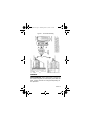
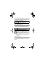
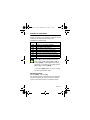
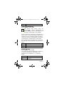
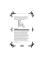
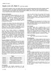
PPIN_EI01.fm Page -1 Thursday, June 19, 2003 1:51 PM
PIN and Proximity Reader
For Access Control Systems
(CR-R885-BL)
Installation and Operating Instructions
V1.1
PPIN_EI01.fm Page 0 Thursday, June 19, 2003 1:51 PM
PPIN_EI01.fm Page 1 Thursday, June 19, 2003 1:51 PM
TABLE OF CONTENTS
Selecting an Installation Site: .......................2
Mounting and Wiring....................................2
Mounting on Metal Surfaces ..........................3
Technical Specifications................................3
Feedback ...................................................5
Programming..............................................6
Card/Code Options ......................................7
Keypad Communication Format.....................7
Transfer Limit for 4-bits Buffered Format ........8
Display on Card Read...................................9
Keypad Lockout ..........................................9
26-bit Wiegand Card Family Code Setting ..... 10
Reader’s Interface ..................................... 10
Check-in Supervision ................................. 11
Buzzer Setting .......................................... 11
Face Light Intensity ................................... 12
Face Light Operation.................................. 12
Face Light Colour ...................................... 12
Changing the Installer Code........................ 13
Panic Alarm .............................................. 13
Resetting to Default................................... 13
Card Presentation Test............................... 14
Warranty ................................................. 14
PosiPin 1
PPIN_EI01.fm Page 2 Thursday, June 19, 2003 1:51 PM
INSTALLATION
For PosiPin to function correctly with the access
control system, some programming may be
required in the controller or control panel of the host
system. For further instructions, refer to the
appropriate manual. Only explanations directly
concerning PosiPin’s programming will be included
in this manual.
SELECTING AN INSTALLATION SITE:
• Avoid wiring the PosiPin cables in the same conduit
as AC power cables, lock power or signal wiring.
• Reader wiring must remain a minimum of 30cm
(12in) away from other wiring, such as wiring for
AC power, computer data, telephones, electric
locks, etc.
• Avoid sites within 1.1m (3.5ft) of computer
monitors or CRTs.
• Avoid sites near sources of broad spectrum EMI
noise, such as motors, pumps, generators, DC to
AC converters, AC switching relays, power
supplies, and light dimmers.
• Avoid sites near potential sources of RF signals,
such as cellular phones, two-way radios, etc.
MOUNTING AND WIRING
After selecting a site for the PosiPin, use the
mounting plate as a guide to drill two holes to
secure the mounting plate and a hole for the cable
0.95cm to 2.54cm (0.375in to 1in) wide. Place a
grommet around the edge of the hole for the cable.
Prepare PosiPin’s cable by cutting the cable jacket
back 3.175cm (1.25in) and stripping the wires back
2 Installation Manual
PPIN_EI01.fm Page 3 Thursday, June 19, 2003 1:51 PM
0.635cm (0.25in). Splice PosiPin’s wires with a
recommended cable wire. Route the cable to the
controller and connect as shown in Figure 1:
Connection Drawing on page 5.
MOUNTING ON METAL SURFACES
Although the read range may slightly decrease,
PosiPin can be mounted on metal. However, do not
box in or surround the card reader with any kind of
metal. If the reader must be installed in a metal
enclosure, ensure that the face of the card reader is
not covered and that at least 1.6" (4cm) remain
between the card reader and the metal on all sides
of the card reader.
TECHNICAL SPECIFICATIONS
Input Voltage:
Input Current:
Consumption:
Frequency:
Operating Temp:
Output formats:
Cable Distance:
Typical: 13.8Vdc, min.: 11.0Vdc,
max: 14.5Vdc
Typical: 65mA @ 12.5Vdc, with
card: 105mA
Typical: 812mW @ 12.5Vdc, with
card 1.31mW
Exciter Field: 125KHz Pulse
Modulated, receive low:
12.500KHz, Receive high:
15.625KHz
-25°C (-13°F) to +65°C (+149°F)
Reader: 26- and 37-bit Wiegand
Keypad: 8-, 26- and 37-bit
Wiegand, 4-bit with or without
parity, and 4 bits buffered with or
without parity
152.4m (500ft.)
PosiPin 3
PPIN_EI01.fm Page 4 Thursday, June 19, 2003 1:51 PM
Suggested Cables: 22AWG, 0.8mm, Multi-conductor,
Alpha 5196, 5198
18AWG, 1.2mm, Multi-conductor,
Alpha 5386, 5388
Belden 9553, 18AWG, 6conductor, stranded w/overall
shield
Indicators:
Beeper, red LED, green LED, blue
or green Face Light
Weight:
280g (9.8 oz.)
Material:
Black, UV resistant, ABS plastic
Dimensions:
99.5mm (5.75in.) x 118.5mm
(2in.) x 19.5mm (1in.)
Approvals:
Compliant to all EU and
EFTA countries except Greece
according to RTT&E directives.
4 Installation Manual
PPIN_EI01.fm Page 5 Thursday, June 19, 2003 1:51 PM
Figure 1: Connection Drawing
FEEDBACK
Visual Feedback: When information is entered on
the reader’s keypad, the red and/or green LEDs will
flash, remain constant or extinguish depending on
the operation.
PosiPin 5
PPIN_EI01.fm Page 6 Thursday, June 19, 2003 1:51 PM
Confirmation Beep: When an operation is
successfully entered, the reader emits a rapid series
of beep tones (“beep-beep-beep-beep-beep”).
Rejection Beep: When the system reverts to a
previous status or an operation is incorrectly
entered, the reader emits one long beep tone
(“beeeeeeeeeep”).
PROGRAMMING
Ensure that corresponding programming is
completed in the control panel or controller
connected to the PosiPin.
To Program:
1. Press and hold the [CLEAR] key for 4 seconds.
The reader emits a confirmation beep and the
green LED illuminates.
2. Enter the [INSTALLER CODE]. Press the
[ENTER] key.
(default:000000) Reader emits a confirmation
beep and the green LED flashes.
3. Enter the 3-digit [SECTION]. Press the
[ENTER] key.
Reader emits a confirmation beep and the
green LED stops flashing.
4. Enter the required [DATA]. Press the [ENTER]
key.
The reader emits a confirmation beep and the
green LED flashes.
6 Installation Manual
PPIN_EI01.fm Page 7 Thursday, June 19, 2003 1:51 PM
5. To program another section, repeat steps 3
and 4. To exit programming mode, press and
hold the [CLEAR] key for 4 sec.
The reader emits a rejection beep and the
green LED extinguishes.
CARD/CODE OPTIONS
Section [001] - Default: [3]
PosiPin can function as a reader, a keypad or as
both combined.
Enter Description
[0]
[1]
[2]
[3]
Keypad and reader disabled.
For programming only.
Reader only enabled. A user must
present a valid card to the reader for
Access Granted.
Keypad only enabled. A user must enter
a valid code on the keypad for Access
Granted.
Keypad and reader enabled. A user
must present a valid card and enter a
valid code for Access Granted.
KEYPAD COMMUNICATION FORMAT
Section [002] - Default: [1]
PosiPin must use the same keypad communication
format as the controller.
Enter Description
[0]
[1]
8-bit Wiegand (Motorola ARK).
26-bit Wiegand, default used by
Centaur (also see section [006]).
PosiPin 7
PPIN_EI01.fm Page 8 Thursday, June 19, 2003 1:51 PM
[2]
[3]
[4]
[5]
[6]
37-bit Wiegand (Not supported by
Centaur).
4 bits without parity.
4 bits with parity.
4 bits buffered without parity
(also see section [003]).
4 bits buffered with parity (also see
section [003]).
Note that BCD is not supported.
TRANSFER LIMIT FOR 4-BITS BUFFERED
FORMAT
Section [003] - Default: [00]
This feature sets the number of digits retained in
memory before the data is sent to the controller. For
example, if section [003] is set at 05, PosiPin will
transmit once five digits are entered on the keypad.
This feature only applies when the format
programmed in Section [002] is set for
Option [5]: 4 bits buffered without parity or
Option [6]: 4 bits buffered with parity.
Enter
Description
If section [002] is Option [5]:
[01] to [11]
4 bits buffered without parity.
If section [002] is Option [6]:
[01] to [10]
4 bits buffered with parity.
8 Installation Manual
PPIN_EI01.fm Page 9 Thursday, June 19, 2003 1:51 PM
DISPLAY ON CARD READ
Section [004] - Default: [3]
PosiPin’s response to a card being presented to the
reader can be adjusted according to the
installation’s requirements.
Enter
[0]
[1]
[2]
[3]
[4]
[5]
[6]
[7]
Description
Display on Card Read disabled
Red Status LED flashes*
Green Status LED flashes*
Red and green Status LEDs flash*
Face Light flashes
Face Light and red Status LED flash
Face Light and green Status LED flash
Face Light and both Status LEDs flash
Select [0] in Face Light Operation (see
page 12) to enable options [0] to [3] in
section [004] or select [1] in Face Light
Operation, (see page 12) to enable options
[4] to [7] in section [004].
* If section [103] (page 12) is set to [1],
the face light will also flash.
KEYPAD LOCKOUT
Section [005] - Default: [0]
The PosiPin keypad comes with a feature that will
lock the keypad for 60 seconds when an installer
code is entered incorrectly 3 consecutive times.
PosiPin 9
PPIN_EI01.fm Page 10 Thursday, June 19, 2003 1:51 PM
Enter
[0]
[1]
Description
Keypad Lockout disabled.
Keypad Lockout enabled.
26-BIT WIEGAND CARD FAMILY CODE
SETTING
Section [006] - Default: [000]
When the keypad is enabled, the card’s family code
must be programmed in order for the keypad to
recognize the user’s PIN. When a user enters a PIN
on the keypad, PosiPin will automatically add the
family code programmed in section [006] to the
beginning of the PIN before transmitting the data to
the controller. Therefore, also ensure that all cards
to be used with the PosiPin contain the same family
code.
This feature only applies when the
communication format programmed in
Section [002] is set for Option [1]: 26-bit
Wiegand.
Enter
[0] to [255]
Description
Cards’ Family Code.
READER’S INTERFACE
Section [007] - Default: [0]
The reader component of the PosiPin must be
programmed to use the same reader
communication format as the controller.
Enter
[0]
Description
26-bit Wiegand.
10 Installation Manual
PPIN_EI01.fm Page 11 Thursday, June 19, 2003 1:51 PM
[1]
37-bit Wiegand.
CHECK-IN SUPERVISION
Section [008] - Default: [0]
This feature only applies when the
communication format programmed in
Section [002] is set for Option [1]: 26-bit
Wiegand or Option [2]: 37-bit Wiegand.
When no actions are performed on the PosiPin for a
period of time, it will communicate its status to the
controller every 30 seconds by sending a code to
confirm its presence (26-bit Wiegand = 255:65535;
37-bit Wiegand = 65535:65535). If the PosiPin
does not communicate its status every 30 seconds,
the controller can be programmed to generate an
alarm.
Enter
[0]
[1]
Description
Check-in Supervision disabled.
Check-in Supervision enabled.
BUZZER SETTING
Section [101] - Default: [3]
The number of beep tones emitted as a response to
a card being presented to the reader can be
adjusted from 0 (disabled) to 7 (7 rapid beep
tones).
Enter
[0] to [7]
Description
Number of beep tones per
response.
PosiPin 11
PPIN_EI01.fm Page 12 Thursday, June 19, 2003 1:51 PM
FACE LIGHT INTENSITY
Section [102] - Default: [4]
The Face Light’s illumination can be adjusted
according to the installation’s requirements from 0
(extinguished) to 8 (brightest).
Enter
Description
[0] to [8] Face Light’s intensity level.
FACE LIGHT OPERATION
Section [103] - Default: [0]
The Face Light can be set to remain illuminated
continually or can follow the Status LEDs’ state.
Enter Description
[0]
[1]
Face Light constant.
Face Light follows Status LEDs.
If [0] in section [103] is selected, this will
override options [4] to [7] in Display on
Card Read (see page 9). In addition, if [1] in
section [103] is selected, this will override
[0] to [3] in Display on Card Read (see
page 9).
FACE LIGHT COLOUR
Section [104] - Default: [0]
The Face Light’s colour can be blue or green as
desired.
12 Installation Manual
PPIN_EI01.fm Page 13 Thursday, June 19, 2003 1:51 PM
This feature only applies when Face Light
Operation programmed in Section [103] is
set for Option [0]: Face Light constant.
Enter
[0]
[1]
Description
Blue Face Light.
Green Face Light.
CHANGING THE INSTALLER CODE
Section [200] - Default: 000000
The Installer Code is used to enter PosiPin’s
programming mode. The Installer Code is six digits
long where each digit can be any value from 0 to 9.
PANIC ALARM
A panic code can be generated and transmitted to
the controller by pressing and holding the [CLEAR]
and [ENTER] keys for 2 seconds (26-bit Wiegand =
255:65534; 37-bit Wiegand = 65535:65534).
This feature only applies when the
communication format programmed in
Section [002] is set for Option [1]: 26-bit
Wiegand or Option [2]: 37-bit Wiegand.
RESETTING TO DEFAULT
To reset PosiPin to factory defaults, disconnect its
power supply. Press and hold the [1] and [2] keys
simultaneously while reconnecting its power supply.
CARD PRESENTATION TEST
Present the card to the reader as shown in the figure
below. Place the card parallel to the PosiPin reader
and move it toward the reader until the card code
PosiPin 13
PPIN_EI01.fm Page 14 Thursday, June 19, 2003 1:51 PM
displays on the controller screen. At this point, the
card is read, decoded, data transmitted to the
controller and the controller has responded
accordingly. To read the card again, remove and reinsert the card into the reader's field.
WARRANTY
The Seller warrants its products to be free from
defects in materials and workmanship under normal
use for a period of one year. Except as specifically
stated herein, all express or implied warranties
whatsoever, statutory or otherwise, including
without limitation, any implied warranty of
merchantability and fitness for a particular purpose,
are expressly excluded. Because Seller does not
install or connect the products and because the
products may be used in conjunction with products
not manufactured by Seller, Seller cannot
guarantee the performance of the security system.
Seller obligation and liability under this warranty is
expressly limited to repairing or replacing, at
Seller's option, any product not meeting the
specifications. In no event shall the Seller be liable
14 Installation Manual
PPIN_EI01.fm Page 15 Thursday, June 19, 2003 1:51 PM
to the buyer or any other person for any loss or
damages whether direct or indirect, consequential
or incidental, including without limitation any
damages for lost profits stolen goods or claims by
any other party caused by defective goods or
otherwise arising from the improper, incorrect or
otherwise faulty installation or use of the
merchandise sold.
Notes
PosiPin 15
PPIN_EI01.fm Page 16 Thursday, June 19, 2003 1:51 PM
16 Installation Manual
PPIN_EI01.fm Page 17 Thursday, June 19, 2003 1:51 PM
PPIN_EI01.fm Page 18 Thursday, June 19, 2003 1:51 PM
Printed in CANADA 06/2003
PPIN-EI01