1
>pDRIVE<
Operating instructions
>pDRIVE< MX basic
>pDRIVE< MX plus
>pDRIVE< MX plus-hydro
>pDRIVE< MX multi-basic
>pDRIVE< MX multi-plus
>pDRIVE< MX top
>pDRIVE< MX top-hydro
with software PBA6
Safety Instructions
The following symbols should assist you in handling the instructions:
General information, note exactly!
Dangerous voltages! Danger of life!
Advice, tip!
The requirements for successful commissioning are correct selection of the unit, proper projection and mounting. If you have any further
questions, please contact the supplier or call the manufacturer of the unit directly.
Capacitor Discharge!
Before performing any work on or in the unit, disconnect from the mains and wait at least 5 minutes until the D.C. link capacitors have been
fully discharged to make sure that the device is no longer live.
Automatic Restart!
With certain parameter settings it may happen that the frequency inverter starts up automatically when the mains supply returns after a power
failure. Make sure that no persons and no other equipment is in danger.
Commissioning and Service!
Work on or in the unit must be done only by duly qualified staff and in full compliance with the appropriate instructions and pertinent
regulations. Note that a fault may cause potential-free contacts and/or PCBs to carry mains potential. To avoid any risk to humans, obey the
regulations concerning "Work on Live Equipment" explicitly.
Terms of delivery:
Our deliveries and services are based on the "General Terms of Delivery of the Austrian Electrical Industries" in the latest edition.
Specifications in this instruction:
We are constantly striving to improve our products and adapt them to the latest technical development. Therefore, we reserve the right to modify
the specifications given in this instruction at any time, particular those referring to measures and dimensions. All planning recommendations and
connection examples are non-binding suggestions for which we cannot accept any liability, particularly since the regulations to be complied with
depend on the type and location of the plant and on the use of the instruments.
Regulations:
It is the user’s responsibility to ensure that the instrument and its component parts are used in compliance with applicable regulations. It is not
permitted to use these instruments in residential areas without special measures to suppress radio frequency interference.
Patents and trademarks:
Please note that we do not guarantee any connections, instruments or processes described herein to be free from patent or trademark rights of
third parties.
Keep this instruction at hand near the unit!
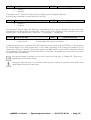
Quick Start
1
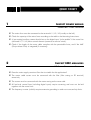
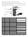
INSPECT POWER WIRING
POWER CABLE – FUSES – DISTANCES
The mains lines must be connected to the terminals L1 / L2 / L3 (usually on the left).
Check the capacity of the mains fuses according to the table in the Mounting Instructions.
A (pre-mating) auxiliary contact should act on the digital input “pulse enable” if the motor line
(terminals U / V / W) has a control element (contactor or service switch).
Check if the length of the motor cable complies with the permissible limits, and if the AMF
(Output Motor Filter) is integrated (if necessary).
2
INSPECT EMC MEASURES
RFI-FILTER – GROUNDING – SCREENING
Does the mains supply contain a filter that is suitable for this application?
The motor cable screen must be connected with the filter (filter casing or PE terminal)
extensively.
The screen must be connected with the motor casing on the motor side.
All low-level control lines (including digital inputs) require screening and must not be laid
together with the motor lines.
The frequency inverter (cubicle) requires extensive grounding in order not to exceed trip limits.
Quick Start
3
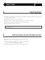
INSPECT MECHANICS
ENGINE – MOTOR – INVERTER
Check all components for damage during transport. All transport safety devices (e.g. at the
motor) must be removed.
Transport components must be mounted tidy.
Check if there is enough cooling (for the motor as well as for the inverter).
Check the mechanic connection between motor and machine.
Is the whole drive ready to switch on ?
Release given from: ...........................................................................................................
4
SWITCH ON MAINS VOLTAGE AND CARRY OUT TESTS
MAINS VOLTAGE – TESTS – AUXILIARY VOLTAGE
Check the 24 V DC buffer voltage (if used) and switch it on.
Are the three phase voltages given and are they symmetrical ?
(See instructions in "Working with live lines" !)
The mains voltage has to be 400V ±15%, 50/60Hz ±5%.
Quick Start
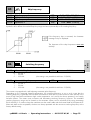
5
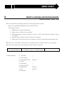
SELECT A SUITABLE APPLICATION MACRO
APPLICATION MACRO – PUMPS – FANS
The inverter has pre-settings (macros) for three typical drive modes.
Macro 2 is especially designed for pump and fan drives.
This settings contain:
Adaptation on square load torque
High continuous load at low overload
Switching between manual reference value (0...10V) and automatic reference value
(4...20mA)
Locking reverse rotation and 5 Hz minimum frequency
Digital inputs for Start, switch-over of reference values, external fault and external reset
Macro M1 is the default setting (for drives which require a constant torque, e.g. conveyors).
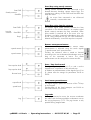
Select the desired macro with parameter B2.03 "Macro selection".
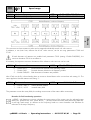
B2.03 Macro Selection
Possible settings:
0…Conveyor → e.g.: 2…Centrif. pump
0... Conveyor
—
1...Piston pump
—
2...Centrifugal pump
Macro 2
3...Coiler
—
4...Test bench
—
5...Pump with PID
—
6...Exhaust fan
Macro 2
7...Fan
Macro 2
8...Separator
—
…………………………..
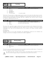
Quick Start
6
THE "KEY" PARAMETERS
SHORT MENU – PARAMETERS – MATRIX FIELD B5
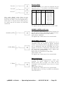
Chapter B5 "Short menu" lists the "key" parameters and the configuration of the control
terminals for each application.
All parameter modifications are automatically included into the list of the "Short menu" and are
deleted again, whenever the factory default is reset.
Thus, the short menu provides a clear overview of all parameter settings.
All parameter modifications are safely stored automatically after 5 minutes or by switching to
matrix field A1 "Home" (or set parameter A1.00 "Save backup" to "1 Store" and then back to
"0", if you use the program MatriX).
Parameter
Pre-settings Macro 2
Selected adjustment
D1.00 AIV Selection
freq. ref. manual
………………………………………...
D1.01 AIV Value 0%
0,00 Hz
………………………………………...
D1.02 AIV Value 100%
50,00 Hz
………………………………………...
D1.04 AIC Selection
freq. ref. manual
………………………………………...
D1.06 AIC Value 0%
0,00 Hz
………………………………………...
D1.07 AIC Value 100%
50,00 Hz
………………………………………...
D2.00 DI1 Selection
Start FWD
………………………………………...
D2.01 DI2 Selection
Manual (Auto)
………………………………………...
D2.02 DI3 Selection
Ext. fault
………………………………………...
D2.03 DI4 Selection
Ext. reset
………………………………………...
D3.00 AO1 Selection
|Output frequency|
………………………………………...
D4.01 Relay output 1
Ready + Run
………………………………………...
Quick Start
7
ENTER MOTOR DATA
NOMINAL POWER – NOMINAL SPEED – NOMINAL CURRENT
Enter the values for nominal power, nominal current, nominal voltage, nominal frequency and
nominal speed from the motor output plate in matrix field B3.
B3.00 Nom. power
………………………………… kW
B3.01 Nom. current
………………………………… A
B3.02 Nom. voltage
………………………………… V
B3.03 Nom. frequency
………………………………… Hz
B3.04 Nom. speed
………………………………… rpm
All parameter modifications are safely stored automatically after 5 minutes or by switching to
matrix field A1 "Home" (or set parameter A1.00 "Save backup" to "1 Store" and then back to "0",
if you use the program MatriX).
Quick Start
8
START AUTOTUNING (SELF-ADAPTATION)
MOTOR VALUES – CABLE RESISTANCE – AUTOTUNING
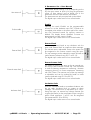
Use parameter B4.00 to start automatic tuning of the motor.
(the motor does not start turning !)
! Motor(s) must be connected !
! Pulse enable signal must exist !
! The motor must not rotate !
The individual measuring cycles can be observed on the display.
(period of 1 to 4 minutes, depending on motor size)
B4.00 Start tuning
Start the routine with "1"
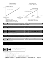
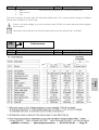
9
Autotuning finished
yes
no
START THE DRIVE IN LOCAL MODE
LOCAL MODE – START/STOP – DISPLAY
Press the "Local/Remote" key in order to activate the display "Local" (bottom left).
Press the "Start" key and slowly increase the frequency setting by pressing the "Arrow up" key.
Check the direction of motor rotation. If the motor rotates in the wrong direction, it is not
necessary to reconnect the motor cables. With parameter C3.03 the rotary field can be
inverted.
C3.03 Phase rotation
U-V-W / A-B-C
Rotary field inverted
yes
no
Try different speeds during checking the charge of the drive in matrix field A2.
A2.02 Motor load (%)
Shows the load of the motor in percent of the motor nom. current.
A2.03 Motor current (A) Shows the actual motor current in ampere.
Quick Start
The three analogue monitors of the display can be adjusted with parameters A6.00 to A6.02.
A6.00 Select zone 1
0…Output frequency
…………………………………………..
A6.00 Select zone 2
11…Speed reference
…………………………………………..
A6.00 Select zone 3
5…Motor current
…………………………………………..
10
REMOTE MODE
REMOTE MODE – CONTROL COMMANDS – ACTUAL VALUES
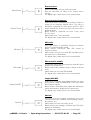
Check the active reference values and control commands using parameters A4.00 to A4.22
before switching back to remote control mode.
A4.01 AIV scaled (Hz)
Shows the scaled reference value of AIV (0…10V)
A4.03 AIC scaled (Hz)
Shows the scaled reference value of AIC (4…20mA)
A4.14 Digital input X1
Shows the state of the digital inputs at terminal X1 in 4 bits
Display A4.14 (1...terminal closed):
Activate "Test min. value" or "Test max. value" for the analogue outputs in order to check the
actual value feedback sent to the control unit. The relay outputs can also be set to "ON" for
testing purposes.
D3.00 AO1 selection
act. value → 20...Test min. val. → 21...Test max. val. → act. value
D4.01 Relay output 1
act. value → 0...not used → 25...ON (+24V) → act. value
Switch back to remote control mode, check the power parameters and the reactions to the
control commands again.
Quick Start
11
DATA STORAGE AND PROTOCOLS
CODE LOCK – PARAMETER LIST – DATA STORAGE
Adjust parameters which block unauthorized operating modes:
E4.00 and E4.01 lock in position "2 Remote only" the switch over to local mode.
E4.00 Loc/Rem ref.
0…Local/Remote
………………………………………………
E4.01 Loc/Rem control
0…Local/Remote
………………………………………………
The code lock has to be lifted before parameters can be adjusted, if a value between 1 and
9999 is selected for F6.01.
F6.01 Code value
0
………………………………………………
Use B2.01 "Store User-M1" in order to save all parameter values (including motor data) in
User Macro 1.
B2.01 Store User-M1
Storage of UM1 with "1"
User-Macro stored
yes
no
Manual transfer of all settings from the "Short Menu" B5 (+autotuning data B4.01 to B4.04) to
the start-up log (appendix C of this manual).
With the PC program “MatriX” all parameters can be read-out in doc-mode. Also the whole list
can be printed (see instructions in appendix A !).
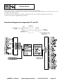
Operating
Operating the Frequency inverter
A
Display
>pDRIVE< MX basic
2
3
4
5
6
A-Display Parameters
8
B-Setup Parameters
17
C-Settings Parameters
35
D-Input/Output Parameters
46
E-Drive Parameters
65
F-Debug Parameters
76
Appendix A
MATRIX Software
Appendix B
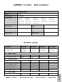
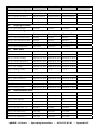
Start-up Report
Appendix C
>pDRIVE< MX basic – Operating instructions – 8 074 157.01/01 – Page 1
MatriX
Please inform your supplier or insurance company in the case of damage or incomplete delivery. The
manufacturer shall not accept responsibility for damage caused during shipment or unpacking.
Report
This manual covers the topics operation & parametrization. Detailed information about the topics
planning, assembly and connection can be found in the Mounting Instructions, information about the
bus connection is provided in the Manuals Profibus PBO1, Interbus GW-IBO1, CANopen GW-CBO1
or DeviceNet GW-DBO1.
Messages
F
Debug
Messages
C
Settings
Operating
The Keypad
The Matrix Philosophy
Parametrization
Shortcuts
Start-up
D
In/Outputs
Page
E
Drive
Topic
B
Setup
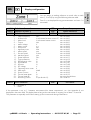
These Operating Instructions describe the functions of the following software:
PBA6 version 8 783 025.00 and higher
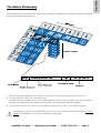
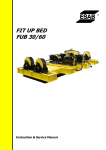
The Keypad
Overview of all
matrix fields
listed according
to their functions
LED status
indicators for:
ready, operation
and trip
"Up" key for:
moving on the
matrix level,
scrolling
parameters within
a matrix field,
increasing
numerical values,
increasing the
reference value in
local mode
Configurable
large-format
LCD graphic
display
"ON" key for:
Start command
in local mode
"OFF" key for:
"Stop" command
in local or
remote mode,
selectable reset
"Local/Remote"
function
key for:
mode switch-over:
keypad / terminal
strip or fieldbus
"Left" key for:
moving on the matrix
level, moving the cursor
to the left; selection of
reverse rotation in local
mode
"Down" key for:
moving on the matrix
level, scrolling
parameters within a
matrix field, decreasing
numerical values;
decreasing the reference
value in local mode
"Right" key for:
moving on the
matrix level,
moving the cursor
to the right;
selection of
forward rotation
in local mode
"Matrix/Param." key for:
switching between basic
display and matrix level,
and between matrix level
and parameter group;
store the new parameter
values
The software type and version are shown using parameters A3.08 and A3.09.
When the front cover is removed, the membrane keyboard can easily be removed, rotated
by 90° and fixed again. Pay attention to the flat strip cable!
>pDRIVE< MX basic – Operating instructions – 8 074 157.01/01 – Page 2
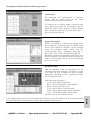
The arrangement of parameters in a matrix system provides the possibility to summarize parameters clearly by
using a three dimensional approach.
• Press the key "Matrix/Parameter" to switch from the matrix level to a parameter group and vice versa.
• The matrix field A1-Home has a special function:
It contains the basic display for the device and parameters which are only accessible with the user software
"MATRIX". All modifications are automatically saved when you switch back to the basic display.
• On the matrix level you can select any matrix field by pressing the up, down, left or right arrow keys.
All changes are stored in the FLASH-ROM when you leave the matrix level and switch back to the basic
display (A1-HOME) or 5 minutes after modifying a parameter.
>pDRIVE< MX basic – Operating instructions – 8 074 157.01/01 – Page 3
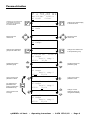
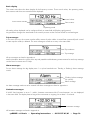
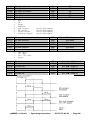
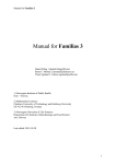
Operating
The Matrix Philosophy
Parametrization
f + 50,00 Hz
Ref+50,0Hz I=300 A
f=fref
A1 Local
Changes from the matrix level
to A1-HOME. All changed
parameters are stored into
the Flash-EPROM.
Changes from basic display
to the matrix level
f +50,00 Hz
A1 Home
I=300 A
Movement in the
matrix level
Movement in the
matrix level
f +50,00 Hz
C2 Ramps
I=300 A
Changes from parameter
group to the matrix level
Changes from matrix level
to the parameter group
f +50,00 Hz
I=300 A
C2 Ramps
Accel. ramp 1
C2 00=
10,0s
Scrolling through the
parameter group
Scrolling through the
parameter group
f +50,00 Hz
I=300 A
C2 Ramps
Decel. ramp 2
C203=
20,0s
Cursor moves to the
parameter value
Cursor moves to the
parameter number
The adjustment of
parameters also
ends by pressing the
Matrix/Param key
f +50,00 Hz
I=300 A
C2 Ramps
Decel. ramp 2
C203=
20,0s
Change of value.
Analogue values are
changed immediately.
Cursor moves to the
tens digit
f +50,00 Hz
I=300 A
C2 Ramps
Decel. ramp 2
C203=
25,0s
>pDRIVE< MX basic – Operating instructions – 8 074 157.01/01 – Page 4
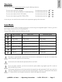
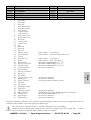
Operating
Shortcuts
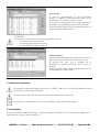
You can move quickly on the matrix level by using the following shortcuts:
To move to the top left (A1 HOME)
Simultaneously press keys
+
To move to the top right (A6 DISPLAY CONFIGURATION)
Simultaneously press keys
+
To move to the bottom left (F1 TEST-HELP)
Simultaneously press keys
+
To move to the bottom right (F6 CODE LOCK)
Simultaneously press keys
+
In this way you can switch from the matrix level to a parameter group at the same time.
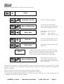
Local Mode
Activate the "LOCAL" mode to operate the frequency inverter using the integrated keypad. To do so, go to the
basic display and press the key "LOCAL/REMOTE".
During LOCAL mode the keys have following function:
Key
Basic functions
Menu level
Parameter group
Start
⎯
⎯
Stop / Reset
Stop / Reset
Stop / Reset
2 x Stop / Reset
2 x Stop / Reset
2 x Stop / Reset = free wheel
Increase ref. value
Navigating on the matrix level
Reduce ref. value
Navigating on the matrix level
REV run
Navigating on the matrix level
Cursor left
FWD run
Navigating on the matrix level
Cursor right
Scroll parameters or increase
parameter values
Scroll parameters or decrease
parameter values
The system is automatically restarted after the removal or confirmation of a trip due to a steady Start
FWD or Start REV signal on the terminal strip.
Local mode can be blocked with parameters E4.00 to E4.03!
If you use option card IO1, you have to activate the pulse enable using digital input DI5 in order to
start the frequency inverter!
The functions of the keys can be connected to the terminal strip with parameter E4.03. As a result, the
keys of the keypad have no functions for local mode (Exception: "Stop" key, if parameter E4.04 was set
to "1 always active" and if impulse contacts are used for the digital input signal).
>pDRIVE< MX basic – Operating instructions – 8 074 157.01/01 – Page 5
Start-up
Follow the steps listed below in order to start up the inverter:
B
Setup
B1
Language selection
Select the operating language
B2
Macro configuration
The selection of an application
macro configures the terminal strip
and creates a suitable short menu.
B3
Motor data
B4
Auto tune
A routine is started in order to tune
the motor exactly with the inverter.
B5
Short menu
Adjustment of the parameters in the
short menu.
Matrix
B2
Dual rating is adjusted with the
motor data:
Version C:
high overload
Version P:
high continuous load
If additional parameters that are not included in the short
menu are required to optimize the system, go to the matrix
fields and set the necessary parameters accordingly.
They are automatically transferred into the short menu.
Macro configuration
After starting up the inverter, you
can transfer the set parameters to
the User Macro by using parameters
B2.01 and B2.02.
During the start-up phase, it might be helpful to supply the frequency inverter with an external 24 V buffer
voltage. This allows you to make adjustments without power supply from the mains (exception: autotuning and
default motor data).
The user interface is fully functional when an auxiliary voltage is applied.
Please use the start-up report in the appendix to record the inverter settings.
You should only transfer those parameters to the list that are shown in the short menu. All parameters that are
not displayed are still set to the factory defaults.
>pDRIVE< MX basic – Operating instructions – 8 074 157.01/01 – Page 6
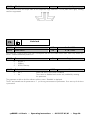
Operating
Description of parameters
B3.03
Nominal frequency [Hz]
Parameter
number
Matrix element
Parameter
name
VICB
25...50...300 Hz
min. value
default
max. value
Parameter marking:
adjustable if Paramet-Access is active 1.)
adjustable if Codelock is disabled 2.)
adjustable in pulse inhibit state 3.)
adjustable parameter
1.) See parameter F6.02
2.) See parameters F6.00 and F6.01
3.) No ON commands are accepted while these parameters are being set.
Key commands are suppressed and steady commands ignored as long as the cursor is positioned right of
the "=" sign.
LCD display contrast regulation
There is a potentiometer for regulating the contrast of the LCD display in the top left corner of the PCB (user
interface - UI).
>pDRIVE< MX basic – Operating instructions – 8 074 157.01/01 – Page 7
A1
Home
Any modifications are stored in the FLASH-ROM:
1.) when leaving the matrix level and switching back to the basic display (A1 HOME) or
2.) five minutes after modifying a parameter.
Operating modes (also displayed in A1.01)
Disabled
The inverter is blocked (does not emit voltage) because:
• there is no enable signal at the terminal strip (digital input DI5_2 or a programmed
input) or
• because the device states "19 Lock switching on" or "0 Not ready to switch on" are
activated for bus control or
• parameter C1.02 is set to "0 Free wheel" and a Stop command is given or
• parameter F6.03 "Pulse inhibit" is set to "1 Yes".
Stop
The inverter is enabled but there has not been a "START" command.
Not enabled
The internal command "Operation release" is missing (only for BUS control).
Trip
The inverter has been switched off due to a trip and the reason is displayed in the
device status field.
Loading
If the function Contactor CTRL is activated, this command shows that the line contactor
has been activated but the necessary DC-voltage has not been reached yet.
Mains off
The inverter input terminals L1, L2, L3 have been enabled by a line contactor using the
function "Contactor CTRL" (C6.00).
Mains missing
"Mains missing" is displayed if the mains supply fails during operation. If the mains is
missing longer than the time set with parameter E3.22 "Undervoltage time delay", the
display changes to "Undervoltage".
Mains disconnected
The digital command "Supply ON/OFF" triggers a safety trip.
Local only
Inverter electronics have been blocked for remote operation with the command "Force
local". Local mode using the keypad (or terminal strip "Local") is still possible.
Heating Motor
The function "Motor heating" has been activated.
AT running
The function "Auto tune" has been activated.
Displays during parametrization
Code lock
You are trying to modify a parameter that is subject to Codelock.
Remedy: disable Codelock F6!
Para locked
1. You are trying to modify a parameter that is subject to parameter lock.
Remedy: Digital input "Paramet-lock" → break contact
2. You are trying to modify a parameter while the switch-over between 2 parameter
sets using B2.04 "Multi-configuration" is active.
Remedy: Change B2.04 to "0 not active".
Pulse release
You are trying to change a parameter that can only be changed if pulse inhibit is
activated. Remedy: Stop command
No access
You are trying to modify a parameter via an unauthorized user terminal.
Remedy: Activate "Paramet.-access" for the respective user terminal (F6.02).
Read only
You are trying to change an actual value (display) parameter.
>pDRIVE< MX basic – Operating instructions – 8 074 157.01/01 – Page 8
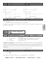
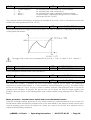
Acceleration (2)
• The drive accelerates according to the settings for the acceleration ramp. The
reference frequency has not been reached yet (fREF > fACT).
• An active limitation (thermal motor model, overload of the frequency inverter,
etc.) during motor operation decreases the frequency (fREF > fACT).
• During motor operation with torque limitation (fREF > fACT).
Deceleration (3)
• The drive decelerates according to the setting for the deceleration ramp. The ref.
frequency is not reached yet (fREF < fACT).
• An active limitation (thermal motor model, overload of the frequency inverter,
etc.) during generator operation increases the frequency (fREF < fACT).
• During generator operation with torque limitation (fREF < fACT).
n = nREF (1)
The actual frequency (speed) corresponds with the reference frequency (speed).
Hysteresis and delay time can be adjusted using parameter D4.08.
Macro 1 (UM1) (6)
Parameter set1 = User Macro1
As soon as the setting "Parameter set2" has been activated with parameter B2.04,
parameter set 1 or 2 is loaded depending on the digital input.
Macro 2 (UM2) (7)
Parameter set2 = User Macro2
If there is a "1"-signal at the respective digital input, the 2nd parameter set (= User
Macro 2) is loaded and "Parameter set 2 (UM2)" is displayed.
Emergency operation
The drive is running in emergency mode.
(15)
Alarms
A monitoring system, which is parametrized to "Alarm" has exceeded the set limit (see
Appendix A).
Limitations
See Appendix A (are only displayed if A6.03 = 1).
A2
A2.00
Motor values
Speed [rpm]
⎯
read only
1.)
Shows the actual motor speed in revolutions per minute. This is also displayed with pulse inhibit, i.e. when the
motor is running out freely. Negative values indicate reverse rotation.
A2.01
Torque [Nm]
⎯
read only
The display is "quadrantal". Display tolerance: ±5% with reference to the nominal torque (friction, iron losses
and ventilation losses are not included).
In drives without encoder, the tolerance is higher in frequency ranges up to 2 Hz.
A2.02
Motor load [%]
⎯
read only
100% correspond to the nominal current of the motor. Display tolerance: ±1.5%
>pDRIVE< MX basic – Operating instructions – 8 074 157.01/01 – Page 9
A
Display
Displays during operation (also displayed in A1.03)
A2.03
Motor current [A]
⎯
read only
Apparent current of the motor in Ampere. Display tolerance: ±1.5% with reference to IN"C" (effective value of the
fundamental oscillation)
A2.04
Shaft power [kW]
⎯
read only
Display tolerance: ±5% with reference to nominal power (calculated from T and n)
A2.05
Apparent power [kVA]
⎯
read only
Display tolerance: ±3% with reference to nominal power (calculated from U and I)
A2.06
Motor voltage [V]
⎯
read only
Display tolerance: ±2% with reference to nominal voltage (effective value of fundamental oscillation)
A2.07
Slip frequency [Hz]
⎯
read only
Displays the slip frequency calculated from the nominal data of the motor and the actual load (calculated from
the torque and the flow).
A2.08
Process speed [m/min]
⎯
read only
1.)
Possibility to display the process speed in m/min. The necessary conversion factor can be adjusted with
parameter A2.10. A2.08 = A2.00 x A2.10.
A2.09
Machine speed [rpm]
⎯
read only
1.)
Possibility to display the machine speed in revolutions per minute. The gearing factor can be adjusted with
parameter A2.11. A2.09 = A2.00 x A2.11.
A2.10
A2.11
Process scaling
Machine scaling
A2.12
Thermal state Motor [%]
VCB
VCB
-10.000...1.000...10.000
-10.000...1.000...10.000
⎯
read only
Displays the calculated thermal state of the motor based on the setting of parameters E2.04 to E2.07.
1.) If the power part has no voltage supply ("Mains off" or "Mains missing" is displayed), these actual
values are set to 0.
A3
A3.00
Inverter values
Output frequency [Hz]
⎯
read only
⎯
read only
Resolution: 0.01 Hz
A3.01
Inverter load [%]
100% correspond to the nominal current of the inverter (Version "C"). Display tolerance: ±1.5%
>pDRIVE< MX basic – Operating instructions – 8 074 157.01/01 – Page 10
A3.02
⎯
DC bus-voltage [VDC]
read only
1.)
A3.03
⎯
Heatsink temperature [°C]
read only
1.)
Display tolerance: ±5% (max. heatsink temperature: 81°C...95°C, depending on size)
Exceeding the limits leads to:
1.) reduction of the switching frequency (see E6)
2.) reduction of the motor current
3.) overtemperature trip.
A3.04
A3.05
A3.06
A3.07
A3.08
A3.09
A3.10
Active switching frequency [kHz]
Drive reference
Nominal current "C" [A]
Hardware version
Software type
Software version
Serial number
⎯
⎯
⎯
⎯
⎯
⎯
⎯
read only
read only
read only
read only
read only
read only
read only
A3.11
Drive status
⎯
read only
The drive states are displayed according to the MX status machine.
0 ..... Not ready to switch on
1 ..... Ready to switch on
2 ..... Charge DC-bus
3 ..... Ready to run
4 ..... Operation release
5 ..... Ramp output release
6 ..... Ramp release
7 ..... Run
8 ..... Motor fluxing
9 ..... Release brake 1
10 ... Crane active
11 ... Jog 1 active
12 ... Jog 1 break
13 ... OFF 1 (deceleration) active
14
15
16
17
18
19
20
21
22
23
24
25
26
27
... OFF 3 (quickstop) active
... Close brake
... DC-brake 1
... DC-brake 2
... OFF 2 (pulse inhibit) active
... Lock switching on
... Fault
... Autotuning in progress
... Power part test in progress
... Release brake 2
... Release brake 3
... Motor heating
... Trip condition 1
... Trip condition 2
Also see documentation "Option Profibus PBO1", "Option Interbus GW-IBO1", "Option CANopen
GW-CBO1" or "Option DeviceNet GW-DBO1" (identical with parameter B6.48).
A3.12
Thermal state BR [%]
⎯
read only
At MX basic devices this parameter has no function.
1.) If the power part has no voltage supply ("Mains off" or "Mains missing" is displayed), these actual
values are set to 0.
>pDRIVE< MX basic – Operating instructions – 8 074 157.01/01 – Page 11
A
Display
Displays the actual DC voltage. Display tolerance: ±2% with reference to the max. DC voltage. If the mains
voltage is 400 V, the DC voltage ranges between 540 and 565 V DC.
A4
A4.00
Reference values
AIV 0...10 V [%]
⎯
read only
Reference value at the analog input terminal AIV (0 V...10 V corresp. to 0% ... 100 %).
A4.01
AIV scaled [Hz] ([%])
⎯
read only
⎯
read only
Scaled reference value of AIV.
A4.02
AIC 0(4)...20 mA [%]
Reference value at the analog input terminal AIC (0(4) mA ... 20 mA / 0% ... 100 %).
A4.03
AIC scaled [Hz] ([%])
⎯
read only
⎯
read only
Scaled reference value of AIC.
A4.04
AI_2 0(4)...20 mA [%]
Reference value at the analog input terminals (AI+ , AI- ) of IO1 at the option slot X2.
(0(4) mA ... 20 mA / 0% ... 100 %)
A4.05
AI_2 scaled [Hz] ([%])
⎯
read only
⎯
read only
Scaled reference value of AI_2.
A4.06
AI_3 0(4)...20 mA [%]
Reference value at the analog input terminals (AI+ , AI- ) of IO1at the option slot X3.
(0(4) mA ... 20 mA / 0% ... 100 %)
A4.07
AI_3 scaled [Hz] ([%])
⎯
read only
⎯
read only
⎯
read only
Scaled reference value of AI_3.
A4.08
Pre-set reference [Hz] ([%])
Pre-set reference value.
A4.09
Local reference [Hz] ([%])
Reference value of local motorpotentiometer (keys UP, DOWN on keypad or digital commands +speed local
and -speed local on terminal strip)
A4.10
Remote reference [Hz] ([%])
⎯
read only
Reference value of remote motorpotentiometer (digital inputs +speed remote, -speed remote)
>pDRIVE< MX basic – Operating instructions – 8 074 157.01/01 – Page 12
A4.11
Frequency before ramp
⎯
read only
Currently used frequency reference value before the acceleration integrator.
Frequency after ramp
⎯
read only
A
Display
A4.12
Currently used frequency reference value after the acceleration integrator.
A4.13
Torque limitation [%]
⎯
read only
Currently used reference value for torque limitation.
A4.14
⎯
Digital input X1
read only
1111
This parameter shows the current state ("0" or "1"; in 4 bits) of the digital inputs on the basic card X1: terminals
11 to 14, DI1 to DI4 (from the right to the left).
A4.15
⎯
Digital input X2
read only
State of the digital inputs at the 1st option card IO1
X2: terminals 26 to 29, DI5_2 to DI8_2 (from the right to the left).
DI5
DI6
DI7
DI8
NOTE: DI5_2 will always be set to "1" if there is no option card! → Display: "_ _ _ 1"
A4.16
⎯
Digital input X3
1111
read only
1111
State of the digital inputs at the 2nd option card IO1
X3: terminals 26 to 29, DI5_3 to DI8_3 (from the right to the left).
A4.17
Drive control word
⎯
read only
This parameter displays the internal control word of the drive. With the control word the MX Status machine is
controlled. Hexadecimal presentation is used for the display.
Further instructions are included in the manuals "Option Profibus PBO1", "Option Interbus GW-IBO1", "Option
CANopen GW-CBO1" and "Option DeviceNet GW-DBO1", parameter B6.47.
A4.18
A4.19
A4.20
A4.21
A4.22
Bus-reference
Bus-reference
Bus-reference
Bus-reference
Bus-reference
1
2
3
4
5
scale
scale
scale
scale
scale
⎯
⎯
⎯
⎯
⎯
read only
read only
read only
read only
read only
Parameters A4.18 to A4.22 display the BUS reference values (PZD2 to PZD6) as standardized values that are
created by reference value destinations.
Further instructions are given in the manuals "Option Profibus PBO1", "Option Interbus GW-IBO1", "Option
CANopen GW-CBO1" and "Option DeviceNet GW-DBO1".
>pDRIVE< MX basic – Operating instructions – 8 074 157.01/01 – Page 13
A5
Time / kWh
A5.00
Operating hours motor [h]
⎯
read only
The operating hours meter "Motor" records the time during which the frequency inverter is in the operating
mode "Pulse release"; i. e. voltage is applied to the motor.
(Display is possible by selecting A6.00 to 02!)
If the switch-over to 2 motors B2.04 = "2 Parameterset 1/2 (2 motors)" is used, the operating time of
the selected motor is displayed.
A5.01
Operating hours inverter [h]
⎯
read only
The operating hours meter "Inverter (FI)" records the time during which the frequency inverter is supplied with
voltage (including 24V buffer voltage).
A5.02
kWh-meter [MWh]
⎯
read only
The kWh-meter records how much active energy has been consumed by the motor. Display tolerance: ±3%;
Motor power and generatoric power is recorded (therefore, also a negative value can be displayed).
Display is possible by selecting A6.00 to 02!
A5.03
Power On hour [h]
⎯
read only
The "Power On hour"-meter records the time during which the inverter is connected to mains supply (and the
fan(s) is(are) running).
Operating hours meter, the counter of Power ON hours and kWh-meter cannot be reset by
parametrization!
A5.04
Maintenance at
VB
0.0...0.0...999999 h
The drive will create an alarm message (indicated on display; part of "Alarm 1" and part of "Alarms") when
A5.03 "Power On hour" gets higher than the value set with this parameter. This alarm message can be used,
for example, as an information when the fans should be replaced.
This function is not active, if the value is set to zero.
>pDRIVE< MX basic – Operating instructions – 8 074 157.01/01 – Page 14
A6
You can assign an analog reference or actual value to each
zone (1, 2 and 3) by using the following selection table.
Zone 2 is not displayed during parametrization and zone 1 is
minimized !
A6.00
A6.01
A6.02
Selection of zone 1
Selection of zone 2
Selection of zone 3
0 ...
1 ...
2 ...
3 ...
4 ...
5 ...
6 ...
7 ...
8 ...
9 ...
10 .
11 .
12 .
13 .
14 .
15 .
16 .
17 .
18 .
19 .
20 .
21 .
22 .
A6.03
Output frequency
Inverter load
Motor load
Torque
Motor voltage
Motor current
Shaft power
Apparent power
Motor speed
Process speed
Machine speed
Speed reference
Torque reference
PID reference value
PID feedback
PID error
DC voltage
Operating hours motor
kWh meter
Power On time
Thermal state Motor
Thermal state BR
Autotuning current
View limitation
VCB
VCB
VCB
Hz
% of nominal inverter current "C"
% of nominal motor current
Nm
V
A
kW
kVA
rpm
m/min
rpm
Hz
%
%
%
%
V
h
MWh
h
%
%
A (not for A6.01)
VCB
Output frequency
Speed reference
Motor current
corr. to A3.00
corr. to A3.01
corr. to A2.02
corr. to A2.01
corr. to A2.06
corr. to A2.03
corr. to A2.04
corr. to A2.05
corr. to A2.00
corr. to A2.08
corr. to A2.09
corr. to A4.11
corr. to A4.13
corr. to C4.00
corr. to C4.01
corr. to C4.02
corr. to A3.02
corr. to A5.00
corr. to A5.02
corr. to A5.03
corr. to A2.12
not active for MX basic
corr. to B4.05
not visible
0 ... not visible
1 ... visible
If this parameter is set to 1, limitation interventions like "Motor temperature", etc. (see Appendix A) are
displayed in the status field. The display lasts as long as the intervention is ongoing, but at least 1.5 seconds.
This parameter is especially useful when starting up the inverter and during maintenance.
>pDRIVE< MX basic – Operating instructions – 8 074 157.01/01 – Page 15
A
Display
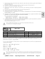
Display configuration
Basic display
This matrix area shows the basic display of the frequency inverter. Three actual values, the operating mode,
device status and the active matrix field are displayed.
Actual values
Active matrix area
Device status
Operating mode
All analog values displayed can be configured freely in matrix field A6 (Display configuration).
Any parameter changes are transferred to the memory as soon as the function HOME is activated again.
Trip messages
In the event of a trip, the inverter switches off by means of pulse inhibit. A stored Start command (local control
or start impulse contact) is deleted. The error message is issued as an entry in the status field.
Trip condition
Trip message
All trip messages are listed in Appendix A.
More information about the cause of the trip and possible troubleshooting measurements for each trip message
can be found in matrix area F1-Help.
Alarm messages
For an alarm message the big display zone 1 is cyclical switched-over. Thereby, a "flashing" alarm message
results.
"Flashing" alarm message
(2s cyclical)
Alarm message
An alarm message needs not to be reseted ! All alarm messages are listed in Appendix A.
Limitation messages
If A6.03 "View limitation" is set to "1 visible", limitation interventions like "Current limitation", etc. are displayed
in the status field. The display lasts as long as the intervention is ongoing, but at least 1.5 seconds.
Limitation message
All limitation messages are listed in Appendix A.
>pDRIVE< MX basic – Operating instructions – 8 074 157.01/01 – Page 16
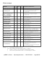
B1
Language selection
Select language
0
1
2
3
4
5
6
7
8
9
...
...
...
...
...
...
...
...
...
...
German
English
French
Netherlands
Polish
Czech
Italian
Spanish
Russian
Bulgarian
VCB
Software: PBA6_A1
yes
yes
yes
yes
−
−
−
yes
−
−
PBA6_A2
yes
yes
yes
−
yes
yes
−
−
−
−
German
PBA6_A3
yes
yes
yes
−
−
−
yes
yes
−
−
PBA6_A4
yes
−
−
−
−
−
−
−
yes
yes
This parameter is not adjusted in the case of factory default!
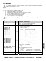
B2
Macro configuration
B2.00
⎯
Macro selected
read only
This parameter displays which macro was selected last.
In the case of user macros, the display also indicates from which factory macro they were derived.
B2.01
B2.02
Store User-Macro 1
Store User-Macro 2
0 ... Start → 1
1 ... Store
2 ... Stored
VCB
VCB
Routine
Routine
The storage routine is activated by changing to line 1.
All parameter adjustments can be transferred to the customer-specific "USER macro" by using this storage
process (user-programmable default values). Often it can be useful to store parameter adjustments in several
steps and thus to make the process of starting up the drive or the whole system easier.
The motor data (Areas B3 and B4) are also stored!
SAFETY NOTE:
After successful start-up of the drive, all parameters should be stored in user macro 1 or 2. This allows
you to restore all parameters with B2.03 (including the motor data and autotuning values) in the event
of a replacement of the power part.
>pDRIVE< MX basic – Operating instructions – 8 074 157.01/01 – Page 17
B
Setup
B1.00
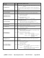
B2.03
Macro selection
0 ....
1 ....
2 ....
3 ....
4 ....
5 ....
6 ....
7 ....
8 ....
9 ....
10 ..
Conveyor
Piston pump
Centrifugal pump
Coiler
Test bench
Pump + PID
Exhaust fan
Fan
Separator
User-Macro 1
User-Macro 2
(UM1 and UM2).
11 .. no change
VICB
Conveyor
Macro M1 (page 22)
Macro M1 (page 22)
Macro M2 (page 25)
The existing parameter settings
(but not the motor data) are
overwritten with the respective
pre-settings.
Macro M3 (page 29)
Macro M2 (page 25)
Macro M2 (page 25)
Macro M1 (page 22)
The existing parameter settings (incl. motor data B3 and B4)
are overwritten with the values from storage location
Exits the parameter without modifications.
To make adaptation of the frequency inverter to the respective application as simple as possible, the library
contains a number of application macros. Selecting a macro automatically activates the suitable functions,
optimizes parameters and configures the terminal strip. At the same time a "Short menu" is created; it contains
only those parameters that are important for the selected application. For comprehensive descriptions of the
macros, see "B5-Short menu".
CAUTION:
The factory defaults of User Macros 1and 2 (state of delivery) do not contain any motor data!
Use F2.01 to load the factory motor data, make adjustments and start autotuning!
B2.04
Multi-configuration
0 ... not active
1 ... Parameter set 1/2 (1 motor)
2 ... Parameter set 1/2 (2 motors)
VCB
not active
Application with one motor (thermal motor protection).
A separate motor protection model is provided for
each motor (thermal motor protection).
Depending on the position of the digital input (parametrization: "20 User Macro 2"), the parameters are loaded
from User Macros 1 or 2.
>pDRIVE< MX basic – Operating instructions – 8 074 157.01/01 – Page 18
As soon as B2.04 has the setting 1 or 2, the function "Para locked" will be active,
i.e. parameters can no longer be changed!
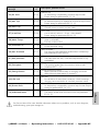
B3
Motor data
B3.00
B3.01
B3.02
B3.03
B3.04
Nominal power [kW]
Nominal current [A]
Nominal voltage [V]
Nominal frequency [Hz]
Nominal speed [rpm]
VICB
VICB
VICB
VICB
VICB
0,0...Default...2500,0 kW
0,0...Default...2500,0 A
0...Default...1000 V
25...Default...300 Hz
0...Default...18000 rpm
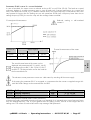
By default, the settings for these parameters correspond to a four-pole standard motor for 400 V with the same
output as the inverter. If you use a motor with different electrical data, please adjust the parameters (e. g. use
of the device as version "C" - high overload).
E.g. for a motor (230/400 V, 22 kW, 50 Hz) in ∆ with a constant torque of up to 87 Hz, the parameters have
to be adjusted as follows:
B3.00 = PN,Motor ⋅ 3 = 22kW ⋅ 3 = 38.1kW
B3.01 = IN∆(230V) = 80A
B3.02 = UNY = 400V
B3.03 = fN ⋅ 3 = 50Hz ⋅ 3 = 87Hz
B3.04 = nN ⋅ 3 = 1460rpm ⋅ 3 = 2530rpm
The nominal speed entered must be smaller than (or equal to) the synchronous speed! Otherwise, the
inverter will calculate the wrong number of pairs of poles and the value displayed as actual speed will
be incorrect.
>pDRIVE< MX basic – Operating instructions – 8 074 157.01/01 – Page 19
B
Setup
1.) Load the desired macro for the first motor, adjust the motor data, start autotuning and make all desired
parameter adjustments.
2.) Parametrize a digital input (parameter D2.00 to 10) for the position "20 User Macro 2".
3.) Use B2.01 to store the new settings in User macro 1.
4.) Connect the second motor, adjust the motor data, start autotuning and make all desired parameter
adjustments.
5.) The same input must be parametrized for the function "20 User Macro 2"!
6.) Use B2.02 to store the new settings in User macro 2.
7.) Set parameter B2.04 to "1 Parameter set 1/2 (1 motor)" or "2 Parameter set 1/2 (2 motors)" and change to
the basic display (A1 - Home).
8.) Depending on the signal at the digital input, the respective parameter set is copied into the block "working
parameter" in the case of pulse inhibit (Stop, Mains off or Disabled).
The current parameter set is displayed.
Digital input Low = User-Macro 1
Display: "Macro 1 (UM1)"
Digital input High = User-Macro 2
Display: "Macro 2 (UM2)"
9.) Set parameter B2.04 to "0" if you want to adjust further parameters in a particular parameter set; make the
desired adjustments and store them with B2.01 and B2.02.
Then parametrize B2.04 again as "1" or "2".
B3.05
Line voltage
0 ... 400 V; 50/60 Hz
VICB
400 V; 50/60 Hz
for line voltage 3 AC 400V (380...415V ± 10%), 50/60Hz ±5%
At >pDRIVE< MX basic devices position 0 is always displayed.
B3.09
Heating current
VCB
1...15...50 %
With this parameter a heating current can be set in % of the nominal motor current. Thereby the motor is
heated during standstill and thus e.g. prevents creation of condensation water.
B4
Auto tune
B4.00
Start tuning
0 ...
1 ...
2 ...
3 ...
4 ...
5 ...
6 ...
7 ...
8 ...
9 ...
10 .
Start 0 → 1
Autotuning
Rotor coefficient
Rotor constant
Stator resistor
I-flux 1
I-flux 2
I-flux 3
I-flux 4
I-flux 5
O.K.
11 . Cancel
VICB
Routine
Starts tuning by selecting line "1".
Autotuning starts and is carried out automatically.
The rotor coefficient is calculated.
The rotor-time constant is calculated.
The resistor of motor and motor cable is measured.
The necessary fluxing current (no-load current) is
calculated in five steps.
Autotuning is finished and the calculated values and
measurements have been transferred to parameters B4.01 to
B4.04.
Press the "Stop" key if you want to stop autotuning although
the process has not finished yet.
The motor is loaded with different voltages and currents during the autotuning routine, but it does not start.
Thereby, specific motor measurements are carried out, and the results are stored in parameters B4.01 to
B4.04.
The complete autotuning process takes 1 to 4 minutes. For autotuning the motor has to be cold.
1.) The tuning requires pulse enable for the inverter; i. e. "Stop" or "Mains off" must be displayed!
2.) The motor must not rotate during the autotuning process!
The most accurate measurement results are achieved if the electronic system has operating
temperature, i.e. mains voltage should be applied to the inverter for at least 2 minutes prior to
autotuning.
There are several reasons for error messages that are issued after the autotuning process:
Message
Possible cause
"12 Error: rotor coeff."
− no enable signal at the terminal strip (e.g. digital input DI5) or via the bus
− no motor connected
"13 Error: rotor time const."
− motor is too big
"14 Error: stator R"
− no motor connected
"15 Error: I-flux"
− motor parameters (B3.00 to 04) have not been entered correctly
− motor rotates
>pDRIVE< MX basic – Operating instructions – 8 074 157.01/01 – Page 20
If you cannot operate the motor satisfactorily (e. g. very small motors or special machines), you can reset the
factory defaults for the autotuning data:
Use F2.01 "Return factory motor" in order to reset the factory defaults in areas B3 and B4. All the other
parameter adjustments and the user macros remain unchanged.
B4.01
B4.02
B4.03
B4.04
Rotor coefficient
Rotor-time constant
Stator resistor
Fluxing current
VICB
VICB
VICB
VICB
0...Default...999999
0.000...Default...4.000 s
0.00...Default...50000.00 mOhm
0.0...Default...2500.0 A
After delivery (or after using F2.01 for resetting the factory defaults), the parameters display typical values for a
motor according to the "P" power of the inverter. These values are replaced by the new data as soon as the
autotuning process has finished.
You can also correct the values → see Service Manual.
B4.05
Autotuning current [A]
⎯
read only
You can display the current supply during autotuning for inspection purposes.
→ See also parameters A6.00 and A6.02.
B5
Short Menu
A selection of parameters which are important for the chosen application is displayed in this matrix area
depending on the macro you have selected.
For many applications, parametrization of the drive will be finished as soon as the parameters displayed in the
short menu have been set or adjusted.
You can make further optimizations, e.g. use option cards or different additional inverter functions, by selecting
and adjusting the necessary parameters on the matrix level. These modified parameters will also be transferred
into the short menu.
The automatic enlargement of the short menu gives you a clear and precise summary of all parameter settings.
All parameters that are not listed in the short menu are stored as factory defaults.
B5 Short menu
C1.00 Incr. start torque
C1.16 Economy mode
C2.00 Accel. ramp 1
C2.01 Decel. ramp 1
C3.00 Min. frequency
e.g. changing parameter C1.02
C1.02 Stop mode
Decel. ramp
→ 0 ... free wheel
1 ... deceleration ramp
2 ... fast stop
B5 Short menu
C1.00 Incr. start torque
C1.02 Stop mode
C1.16 Economy mode
C2.00 Accel. ramp 1
C2.01 Decel. ramp 1
C3.00 Min. frequency
leads to the following changes
compared with the default:
>pDRIVE< MX basic – Operating instructions – 8 074 157.01/01 – Page 21
B
Setup
The autotuning values must be stored in the user macro again!
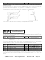
Macro M1 - Drives with high overload (factory setting)
Conveyors
piston pumps
crane drives
separators, etc.
The start torque can be increased to a maximum of 180% for heavy starts (parameter C1.00 "Increase start
torque").
The reference value of 4-20 mA is remote controlled, local mode is operated using the keypad.
Two switches (Start FWD and Start REV) are used for device control; in addition, the terminal strip functions
"2. ramp" and "External reset" are programmed.
If you want to make further device-specific adjustments, use the parameter description and make adjustments in
the matrix area.
The modified parameter settings can be stored in the user macro. All parameter modifications are automatically
transferred to the short menu and are clearly summarized there.
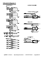
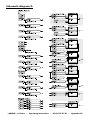
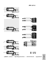
Wiring diagram
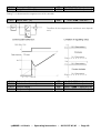
>pDRIVE< MX basic – Operating instructions – 8 074 157.01/01 – Page 22
Parameter
Name
Setting
Notes
B2.03
Macro selection
Conveyor
or: piston pump, separator
C1.00
Increase start torque
0...1...30 %
Setting for 150% start torque
C2.00
Acceleration ramp 1
0.0...5.0...3200.0 s
Setting in s/nom. motor frequency
C2.01
Deceleration ramp 1
0.0...5.0...3200.0 s
Setting in s/nom. motor frequency
C3.01
Maximum frequency
25.00...50.00...300.00 Hz
Setting of the upper frequency limit
C3.02
Direction enable
Enable FWD/REV
Enables forward and reverse rotation
D1.04
AIC selection
f-ref Auto
Frequency ref. value at ref-input AIC (mA)
D1.06
AIC value 0%
-300.00...0.00...300.00 Hz
D1.07
AIC value 100%
-300.00...50.00...300.00 Hz
Defines the frequency range for the analog
signal 4-20 mA
D2.00
DI1 selection
Start FWD
Start/Stop forward (steady contact)
D2.01
DI2 selection
Start REV
Start/Stop reverse rotation (steady contact)
D2.02
DI3 selection
2.ramp
Changes to 2. accel./decel. ramp set
D2.03
DI4 selection
External Reset
Integration of an external reset
D3.00
AO1 selection
⏐Output frequency⏐
Analog output 1 - frequency actual value
(4-20 mA = 0 - fMAX)
D4.01
Relay output 1
Ready + Run
Ready message at digital output RL1
E2.00
Thermistor input Act.
not active
E2.04
IMAX at 0 Hz
0...50...150 %
E2.05
IMAX at fNOM
30...100...150 %
Definition of the motor protection
Currents in % with ref. to INOM,MOTOR
E2.07
Motor-time constant
1...5...3200 min
>5 min: 24V buffering necessary!
All motor data B3.00 to B3.04 are displayed in the short menu!
For the >pDRIVE< MX basic, the short menu also lists parameter B3.05 "Line voltage".
>pDRIVE< MX basic – Operating instructions – 8 074 157.01/01 – Page 23
B
Setup
Short menu for macro M1
Supplement to macro M1
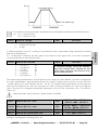
S-ramp for acceleration and deceleration
You can activate an s-ramp in order to ensure a smooth
transition from the standstill of the drive to the acceleration or
deceleration phase and from the acceleration/deceleration
phase to a steady-state speed.
In addition to macro M1, you have to make the following parameter adjustments:
Parameter
Name
Setting
Notes
C2.04
S-ramp
S-ramp step 1, 2 or 3
Make adjustments as required.
C2.05
S-ramp mode
Begin + End
You can also select "Begin only".
Switching to parameter set 2
A special feature of the >pDRIVE< MX inverter is that you can have two different settings for every parameter.
The set motor values, the measured autotuning values and the optimized parameter values are stored at the
locations "User Macro 1" and "User Macro 2". Depending on the digital input, the inverter will operate with
parameter set 1 or 2.
Applications:
− The inverter is alternately used for two motors.
− Parametrization for two different working processes with one motor.
− Alternate operation with and without encoder feedback.
Parameter
Name
Setting
Notes
D2.05
DI7_2 selection
User Macro 2
Assignment of the function to DI7_2
B2.01
Store User-M1
Start routine with 1
B2.02
Store User-M2
Start routine with 1
B2.04 *)
Multi-configuration
Para.Set 1/2 (1 motor)
Select line 1 to initiate the storage process
or Para-Set 1/2 (2 motors)
*) Parameter adjustments are blocked as soon as the parameter is in position 1 or 2.
For instructions on the correct setting process, see parameter B2.04.
>pDRIVE< MX basic – Operating instructions – 8 074 157.01/01 – Page 24
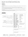
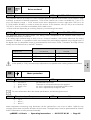
Macro M2 - Drives with high steady load (n2 - load moment)
You can change to the higher rated motor power "P" by adjusting the respective motor data in parameters
B3.00 to B3.01.
The energy saving function "Economy mode" is activated at step 1. The frequency reference value is set using 2
analog inputs. The 0-10 V input is active, if the switch "Manual (Auto)" is closed. Otherwise, the default values
are transmitted via the current reference value input AIC.
The devices are controlled with Start FWD, reverse rotation is blocked. In addition, the terminal strip functions
"External fault" and "External reset" are programmed.
If further device-specific adjustments are necessary, please use the parameter description and adjust the
parameters via the matrix area. The modified parameter settings can be stored in the user macro. All parameter
modifications are automatically transferred to the short menu and are clearly summarized there.
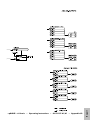
Wiring diagram
>pDRIVE< MX basic – Operating instructions – 8 074 157.01/01 – Page 25
B
Setup
Centrifugal pumps
exhaust fans
fans, etc.
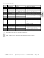
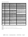
Short menu for macro M2
Parameter
Name
Setting
Notes
B2.03
Macro selection
Centrifugal pump
or: exhaust fan, fan
C1.16
Economy mode
Step 1
Energy saving mode, step 1
C2.00
Acceleration ramp 1
0.0...10.0...3200.0 s
Setting in s/nom. motor frequency
C2.01
Deceleration ramp 1
0.00...10.0...3200.0 s
Setting in s/nom. motor frequency
C3.00
Minimum frequency
0.00...5.00...300.00 Hz
Setting of the lower frequency limit
C3.01
Maximum frequency
25.00...50.00...300.00 Hz
Setting of the upper frequency limit
D1.00
AIV selection
Frequency ref Manual
Manual frequency reference value as
0...10 V signal at analog input AIV
D1.01
AIV value 0 %
-300.00...0.00...+300.00 Hz
D1.02
AIV value 100 %
-300.00...50.00... +300.00 Hz
D1.04
AIC selection
Frequency ref Auto
D1.06
AIC value 0 %
-300.00...0.00...+300.00 Hz
D1.07
AIC value 100 %
-300.00...50.00... +300.00 Hz
Defines the frequency range for the analog
signal 4-20 mA
D2.00
DI1 selection
Start FWD
Start/Stop (forward only - steady contact)
D2.01
DI2 selection
Manual (Auto)
Change to manual f-ref. value
D2.02
DI3 selection
External fault
Integration of an external fault
D2.03
DI4 selection
External reset
D3.00
AO1 selection
⏐Output frequency⏐
D4.01
Relay output 1
Ready + Run
E1.00
Current max. value
125 %
E2.00
Thermistor input Act.
not active
E2.05
IMAX at fNOM
30...100...150 %
E2.07
Motor-time constant
1...5...3200 min
E3.11
External fault Activat.
N.O. Ready + Run
Defines the frequency range for the analog
signal 0...10 V
Automatic frequency ref. value as 4-20 mA
signal at analog input AIC
Integration of an external reset
Analog output 1 - frequency actual value
(4-20 mA = 0 - fMAX)
Ready message at digital output RL1
IMAX - limitation with reference to IN"C"
Definition of the motor protection.
Currents in % with ref. to INOM,MOTOR
>5 min: 24 V buffering necessary!
Ext. fault is integrated by means of a make
contact and monitored in ready + run
mode
All motor data B3.00 to B3.04 are displayed in the short menu!
For the >pDRIVE< MX basic, the short menu also lists parameter B3.05 "Line voltage".
>pDRIVE< MX basic – Operating instructions – 8 074 157.01/01 – Page 26
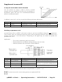
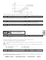
Supplement to macro M2
Fast-Stop with motor brake
Three digital inputs regulate the behaviour if the "OFF" command is activated:
DI1
Start FWD at acceleration ramp 2 / OFF 1
Deceleration at deceleration ramp 2
DI5_2 Start FWD at acceleration ramp 2 / OFF 2
Pulse inhibit = free wheel
DI6_2 Start FWD at acceleration ramp 2 / OFF 3
Fast-stop at deceleration ramp 1
Parameter
Name
Setting
Notes
C1.03
Braking mode
Motor brake A
Depending on the motor use A, B or C.
C2.00
Acceleration ramp 1
0.0...10.0...3200.0 s
Without function!
C2.01
Deceleration ramp 1
0.0...0.1...3200.0 s
Deceleration is adjusted according to the
existing mass and the braking effect.
C2.02
Acceleration ramp 2
0.0...10.0...3200.0 s
Acceleration takes place at the current
limitation if the working load is too big.
C2.03
Deceleration ramp 2
0.0...10.0...3200.0 s
Avoid motor overload by selecting a value
that guarantees that the motor brake does
not work during normal operation.
D2.00
DI1 selection
not used
Is only required by the logic module.
D2.04
DI6_2 selection
2. ramp
Is additionally required by the logic
module.
F4.44
L5 signal to D1
DI1
Required from digital input DI1.
F4.45
L5 signal to D2
DI6_2
Required from digital input DI6_2.
F4.46
L5 logic function
AND
The drive only starts if the contacts for
"Start FWD" and "Fast-stop" are closed.
F4.49
L5 selection
Start FWD
Internal wiring.
>pDRIVE< MX basic – Operating instructions – 8 074 157.01/01 – Page 27
B
Setup
Fans often require a fast-stop mechanism for special operating situations. The new motor brake function of the
>pDRIVE< MX is able to reduce the deceleration time to 10...20%.
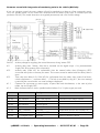
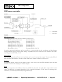
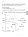
Contactor control with integration of monitoring units in the cubicle (ON lock):
If you use contactor control, the mains voltage will only be switched on as long as a Start command is active.
Thus, the "standby losses" of the inverter are minimized and the lifetime of the fans is increased (see also
parameter C6.00!). The control electronics are supplied permanently with a 24 V buffer voltage.
24V DC
K11
K12
K13
K1.1
K1.2
Auxiliary voltage for supplying the control electronics during "Mains OFF"
Auxiliary relay (max. 100mA, 24V) that is activated via the digital output +24, parametrization
"Supply ON" for activation of the contactor(s).
Auxiliary relay (230V AC) for confirmation from the external safety chain (Emergency OFF).
A renewed start pulse is necessary for restart. The inverter cannot be started while the safety chain is
open.
Time relay (time delay 0.5s; 230V AC) for confirmation from the safety chain (mains fuse blown,
cubicle temperature >, contactor defect, ...). The lock is cancelled by using K11, the error message
is stored by the inverter and a sum error message is displayed.
Contactor for connection to mains supply. It opens after each deceleration, in the case of pulse
inhibit, trip and "Supply OFF".
Both contactors have to work in parallel mode if MX size 5 or 12-pulse supply are used.
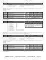
Parameter
Name
Setting
Notes
C6.00
Contactor control
active
D2.00
DI1 selection
Start FWD impulse
D2.01
DI2 selection
Stop Impulse
D2.02
DI3 selection
Manual (Auto)
D2.03
DI4 selection
External Reset
D2.04
DI6_2 selection
ON lock
confirmation from the fuse monitor, etc.
D2.05
DI7_2 selection
Supply ON/OFF
confirmation from the external safety chain
D4.00
+24 digital output
Line ON
output to contactor control
parametrized for calliper control
>pDRIVE< MX basic – Operating instructions – 8 074 157.01/01 – Page 28
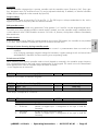
Macro M3 - drives with n2 load moment and process control
You can change to the higher rated motor power "P" by adjusting the respective motor data in parameters
B3.00 to B3.01.
The energy saving function "Economy mode" is activated at step 1. The process reference value is defined via a
voltage signal 0-10 V on AIV, the actual value is reported as a 4-20 mA signal on AIC. The devices are
controlled with Start FWD, reverse rotation is blocked. In addition, the terminal strip functions "external fault"
and "external reset" are programmed.
If further device-specific adjustments are necessary, please use the parameter description and adjust the
parameters via the matrix area. The modified parameter settings can be stored in the user macro. All parameter
modifications are automatically transferred to the short menu and are clearly summarized there.
Wiring diagram
>pDRIVE< MX basic – Operating instructions – 8 074 157.01/01 – Page 29
B
Setup
Pressure, level and
volume control, etc.
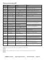
Short menu for macro M3
Parameter
Name
Setting
Notes
B2.03
Macro selection
Pump + PID
C1.16
Economy mode
Step 1
Energy saving mode, step 1
C3.00
Minimum frequency
0.00...5.00...300.00 Hz
Setting of the lower frequency limit
C3.01
Maximum frequency
25.00...50.00...300.00 Hz
Setting of the upper frequency limit
C4.04
PID-controller enable
Yes process
Activates the PID controller
C4.05
Prop. gain (kp)
0.0...20.0...3200.0 %
Controller setting: amplification
C4.06
Integr. time (Tn)
0.00...10.00...320.00 s
Controller setting: integration time
C4.08
Ref. accel. ramp
0.0...10.0...3200.0 s
Setting in s / 100%
C4.09
Ref. decel. ramp
0.0...10.0...3200.0 s
Setting in s / 100%
C4.10
Output scaling -
-300.00...+10.00...+300.00 Hz
Minimal limit of controller output
C4.11
Output scaling +
-300.00...+50.00...+300.00 Hz
Maximum limit of controller output
D1.00
AIV selection
PID-reference value
Reference value as voltage signal 0-10 V
D1.01
AIV value 0 %
-200.00...0.00...+200.00 %
D1.02
AIV value 100 %
-200.00...100.00...+200.00 %
D1.04
AIC selection
PID feedback
D1.06
AIC value 0 %
-200.00...0.00...+200.00 %
D1.07
AIC value 100 %
-200.00...100.00...+200.00 %
D2.00
DI1 selection
Start FWD
Start/Stop (only forward - steady contact)
D2.01
DI2 selection
PID-enable
PID enable signal
D2.02
DI3 selection
External fault
Integration of an external fault
D2.03
DI4 selection
External reset
Integration of an external reset
D3.00
AO1 selection
⏐Output frequency⏐
Analog output 1 - frequency actual value
(4-20 mA = 0 - fMAX)
D4.01
Relay output 1
Ready + Run
Ready message at digital output RL1
E1.00
Current max. value
125 %
IMAX - limitation with reference to IN"C"
E2.00
Thermistor input Act.
not active
E2.05
IMAX at fNOM
30...100...150 %
E2.07
Motor-time constant
1...5...3200 min
E3.11
External fault Activat.
N.O. Ready + Run
Used for reference value adjustment
Actual value > current signal 4-20 mA
Used for actual value adjustment
Definition of the motor protection. Currents
in % with ref. to INOM,MOTOR
>5 min: 24 V buffer necessary!
Ext. fault is integrated by means of a make
contact and monitored in ready + run
mode
All motor data B3.00 to B3.04 are displayed in the short menu!
For the >pDRIVE< MX basic, the short menu also lists parameter B3.05 "Line voltage".
>pDRIVE< MX basic – Operating instructions – 8 074 157.01/01 – Page 30
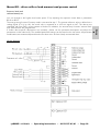
Supplement to Macro M3
Switch-over PID control mode / frequency default
B
Setup
The digital input "PID-enable" explained in macro M3 merely freezes the controller output at the last value or
releases it.
The digital input function "PID active", however, allows you to switch from controller mode to direct frequency
(speed) control and vice versa. In the following example, the direct frequency control is provided by a local
potentiometer and the controller reference default with a 4...20mA signal (this requires the option card IO1).
Parameter settings based on macro M3:
Parameter
Name
Setting
Notes
A6.00
Selection of zone 1
PID error
A6.01
Selection of zone 2
PID-reference value
A6.02
Selection of zone 3
Motor speed
Adjustment of the display for PIDcontroller mode with switch-over to
frequency control
C4.04
PID enable
DI process
Switch-over according to digital input
D1.00
AIV selection
freq. ref Auto
D1.01
AIV value 0 %
-300.00...e.g.10.00...+300.00 Hz
D1.02
AIV value 100 %
-300.00...e.g.50.00...+300 .00Hz
D1.09
AI_2 selection
PID-reference value
D1.10
AI_2 signal type
4...20mA
D1.11
AI_2 value 0 %
-200.00...0.00...+200.00 %
D1.12
AI_2 value 100 %
-200.00...100.00...+200.00 %
D2.01
DI2 selection
PID active
Voltage ref. value for frequency control
with minimum and maximum limit
Controller ref. value as 4...20mA signal
Making contact
controller mode
switches
over
Through permanent feedback from the PID controller output, a smooth switch back to controller mode is
possible.
>pDRIVE< MX basic – Operating instructions – 8 074 157.01/01 – Page 31
to
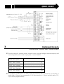
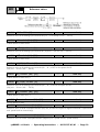
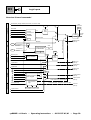
PID process controller with reference value default on the keypad
The inverter works in controller mode without an external calliper and potentiometer, by setting the required
reference value directly on the inverter keypad. Only the actual value signal (e.g. actual pressure value 4...20 mA) is
connected to terminals 3 and 4 on the terminal strip.
Due to jumpers between terminals 9 and 10, as well as 11 and 15, controller mode starts as soon as the mains
voltage is switched on (→ for parametrization of locked (VICB) parameters, switch to local mode and press the Stop
key or open strapping!)
Button
0
RemoteMotorpot.
PID-ref. value (%)
6
0
X1:
(Pressure-)
act. value
4...20 mA
Start / Stop
PID enable
AIC
0V
3
4
0V
DI S
DI 1
DI 2
9
10
11
12
+24
15
PID feedback (%)
6
Start FWD
PID enable
L5
PID mode OK.:
-Mains voltage on
-error OK
-no trip
RL 1
NC 1
NO 1
L6
18
19
20
³1
&
C1+C2
t
+
COMP
-
t
+
COMP
-
+ limit
deviation
- limit
Run
Parameter settings based on macro M3:
Parameter
A6.00
A6.01
A6.02
D1.00
D1.01
D1.02
D4.01
D6.06
D6.07
D6.08
D6.11
D6.12
F4.00
F4.02
F4.03
F4.04
F4.06
F4.08
F4.10
F4.11
F4.12
F4.14
F4.44
F4.45
F4.46
F4.50
F4.51
F4.52
Name
Select. zone 1
Select. zone 2
Select. zone 3
AIV selection
AIV value 0%
AIV value 100%
Relay output 1
Rem. MP selection
Rem. MP min. value
Rem. MP max. value
Rem./MP control
Rem. ref. storage
C1 Signal to E1
C1 reference
C1 function
C1 Hysteresis/Band
C1 Time set
C2 Signal to E1
C2 reference
C2 function
C2 Hysteresis/Band
C2 time set
L5 signal to D1
L5 signal to D2
L5 logic function
L6 signal to D1
L6 signal to D2
L6 logic function
Setting
PID error W-X
PID-ref. value W
PID-feedback X
not used
-300.00...0.01...+300.00 Hz
-300.00...50.01...+300.00 Hz
Output logic L6
PID-reference value
-200.00...0.00...+200.00 %
-200.00...100.00...+200.00 %
Keypad
at Mains-off
PID error
-200.0...e.g.+50.0...+200.0 %
E1 > E2
0.0...2.0...100.0 %
0.0...e.g.30.0...3200.0 s
PID error
-200...e.g.-5.0...+200%
E1 < E2
0.0...2.0...100.0 %
0.0...e.g.10.0...3200.0 s
Output comp. C1
Output comp. C2
OR
Ready + Run
Output logic L5
AND- neg. (D2)
Notes
Adjustment of the display for PID control
mode
After resetting to factory default, the
parameters do not longer appear in the
short menu
Message "PID mode OK"
Remote motorpot. for PID-ref. value default
Lower limit for PID-ref. value
Upper limit for PID-ref. value
Keys on keypad for PID-ref. value
Last ref. value is reactivated after Supply ON
Monitoring of positive PID deviation
With time delay to span from start time until
+error is OK.
Monitoring of negative PID deviation with
delayed feedback if not OK.
Link between the two monitoring modules
for error
Link with Ready and Run feedback
>pDRIVE< MX basic – Operating instructions – 8 074 157.01/01 – Page 32
Supplements to macros M1 to M3
The figures "Configuration of Analog Inputs" in Chapter D1 and "Overview of Control Commands" in Chapter
D2 show the various possibilities for switching between the operating modes.
The switch-over from remote mode (bus control or terminal control) to local mode (on the keypad or locally via
digital inputs) is absolutely smooth.
The switching example describes the switch-over between Profibus control and local control of the motor.
Thereby, both the reference value default and the digital control commands are switched over. In local mode,
the keys of the keypad are replaced by local keys that are integrated via the terminal strip.
f-ref Manual
M
0
BUS:
Main-ref 1
Manual
REV-Rem.
FWD/
REV
A
f-ref Auto
Aux.-ref 2
PID active
0
1
int. fref. value
REM
PID
6
Aux.-ref 3
LOC
Aux.-ref 5
Contr.W.-Bus
B6.01
B6.00
free bits
Commands from
Remote Bus
Contr.W.-RS232
X1:
Start-I loc.
Stop-I loc.
Local
Ext. Reset
Message:
Local
operation
0V
DIS
DI1
DI2
DI3
DI4
+24
P24
P0V
9
10
11
12
13
14
15
16
17
RL1
NC1
NO1
18
19
20
Contr.
Word
Bus
Contr.W.-Rem.
E4.04 C1.02
Enable
E4.03
I
O
(terminal)
Loc
C1.02
Stop
mode
Lock
Contr.W.-Local
Local
(keypad) Local
Local / Remote
Logic
E4.00
int.
Contr.W.
Local switching
commands
Control word
Local switching
frequency
reference value
Aux.-ref 4
E4.01
E4.02
X2: (Option IO 1)
I-enable
REV local
+speed loc.
-speed loc.
Message:
Ready+
Run
Trip
message
DIS
DI5
DI6
DI7
DI8
25
26
27
28
29
RL2
NC2
NO2
RL3
NO3
30
31
32
33
34
Pulse release - DI-5, (+Mains ON, locked, ext. and int. trips)
D6.00
REV-Local
0
+speed local
-speed local
LOC
MP
1
>pDRIVE< MX basic – Operating instructions – 8 074 157.01/01 – Page 33
B
Setup
Switching over to "local control" with local keys
Parameter settings based on macro M1:
Parameter
Name
Setting
Notes
B6.00
Select bus
PROFIBUS DP
B6.01
Select remote
Bus
Parametrization of Profibus DP and
definition of the address
B6.02
Slave address
0...Address...126
B6.03
Stop mode Time out
Trip
B6.04
Time OUT
0.0...e.g. 10.0...3200.0 s
Behaviour at trip of bus with adjustable
delay time.
B6.06
Main reference 1
freq. ref Auto
Frequency ref. default in remote mode
D1.04
AIC selection
not used
D2.00
DI1 selection
Start impulse local
Key command Start (make contact)
D2.01
DI2 selection
Stop impulse local
Key command Stop (break contact)
D2.02
DI3 selection
Local (Rem)
Making contact = local mode
D2.03
DI4 selection
Ext. Reset
Key command trip confirmation
D2.04
DI6_2 selection
REV local
Making contact = reverse
D2.05
DI7_2 selection
+speed local
Key command faster (break contact)
D2.06
DI8_2 selection
-speed local
Key command slower (break contact)
D4.01
Relay output 1
Local operation
Relay closed in local mode
D4.02
Relay output 2_2
Ready + Run
Relay closed for Ready + Run
D4.03
Relay output 3_2
Trip
Relay closed for trip
E4.02
Loc/Rem-switch
Terminals
Switch-over to local mode via terminal strip
E4.03
Ctrl. mode local
Terminals
Keys on keypad replaced by digital inputs
Bit 10, "Control OK" of the bus control word must be set in order to be able to switch back to remote
(bus) mode !
B6
Communication menu
All parameters concerning connection of the fieldbus to the frequency inverter can be found in the
manuals "Option Profibus PB01", "Option Interbus GW-IBO1", "Option CANopen GW-CBO1" and
"Option DeviceNet GW-DBO1" !
>pDRIVE< MX basic – Operating instructions – 8 074 157.01/01 – Page 34
C1
C1.00
C1.01
General functions
Increase start torque
Increase steady torque
VCB
VCB
0...1...30 % (see Macro)
5...10...45 Hz
For applications requiring a high start torque, the start
torque (100% or 150% TN) can be increased to 180%
TN.
e.g. C1.00 = 0% corr. to approx. 100% TN"C"
C1.00 = 1% corr. to approx. 150% TN"C"
C1.00 = 30% corr. to approx. 180% TN"C"
The range, in which this increase is effective, can be
set using parameter C1.01.
The setting of the parameter has no effects on the
function and the result of autotuning.
C1.02
Stop mode
0 ... Free wheel (OFF 2)
1 ... Decel. ramp (OFF 1)
2 ... Fast-stop (OFF 3)
VCB
deceleration ramp
A Stop command is followed by immediate pulse inhibit. The
motor runs out freely.
With this setting, "Disabled" is displayed instead of "Stop".
A stop command is followed by slowing down of the motor
(if possible) according to the set deceleration ramp. On
reaching 0 Hz, a pulse inhibit is issued.
A Stop command is followed by braking of the motor within
the shortest possible time. On reaching 0 Hz, a pulse inhibit
is issued (useful in combination with activated motor brake
C1.03).
Stop command means the Off command from remote or local mode.
C1.03
Braking mode
0 ... No braking function
1 ... Ext. Braking unit
2 ... Motor brake A
3 ... Motor brake B
4 ... Motor brake C
VICB
no braking function
no brake, DC voltage limitation extends the deceleration
ramp as required
for >pDRIVE< MX basic the option DC-connection is not
available
motor brake active, the braking energy is transformed into
heat in the motor, motor cable and inverter. Depending on
the unit size and motor type, the best braking effect is
obtained with setting A, B or C.
Setting 2...4: Motor brake
The "motor brake" is an extremely economic alternative to the external braking unit with resistor. The fast-stop of
a 250 kW drive with 2..3-fold motor mass, for example, is possible within less than 4 seconds.
The motor noise is louder while the motor brake is working.
Most of the braking energy is transformed into heat in the motor.
>pDRIVE< MX basic – Operating instructions – 8 074 157.01/01 – Page 35
C
Settings
For pumps and fans, the setting 0% (TA = approx.
100% TN) is usually sufficient.
Torque
T
Speed of rotation
n
permanent torque of motor
100%
Speed of rotation with
fast-stop without
motor brake
1
brake torque
with motor brake
… with motor brake
k
15
50%
W
50
0k
… without motor brake
W
fN
f (n)
Available brake torque with motor brake
C1.06
Pre-set reference selection
0
1
2
3
4
5
....
....
....
....
....
....
not used
f-ref Manual
f-ref Auto
f-correction
T-limitation
PID reference
Hz
Hz
Hz
Hz
%
%
appr.15% of t Fast stop
t Fast stop
t
Time to stop of a drive with motor brake
VICB
not used
Individual settings that cannot be selected,
have already been assigned by one of the
other reference value sources D1.00,
D1.04, D1.09, D1.14, D6.06 or by a bus
reference value!
The pre-set reference values can be used as a source for various ref. value defaults.
See figure "Configuration of Analog Inputs" in section D1 - Analog Inputs.
C1.07
Pre-set reference 1
VCB
C1.08
Pre-set reference 2
VCB
C1.09
Pre-set reference 3
VCB
C1.10
Pre-set reference 4
VCB
C1.11
Pre-set reference 5
VCB
C1.12
Pre-set reference 6
VCB
C1.13
Pre-set reference 7
VCB
C1.14
Pre-set reference 8
VCB
-300.00...0.00...300.00 Hz
-200.00...0.00...200.00 %
-300.00...0.00...300.00 Hz
-200.00...0.00...200.00 %
-300.00...0.00...300.00 Hz
-200.00...0.00...200.00 %
-300.00...0.00...300.00 Hz
-200.00...0.00...200.00 %
-300.00...0.00...300.00 Hz
-200.00...0.00...200.00 %
-300.00...0.00...300.00 Hz
-200.00...0.00...200.00 %
-300.00...0.00...300.00 Hz
-200.00...0.00...200.00 %
-300.00...0.00...300.00 Hz
-200.00...0.00...200.00 %
The pre-set ref. values are selected using the digital commands Pre-set A, B and C, which must be programmed
for 0...3 digital inputs depending on the required number of pre-set ref. values. See D2 – Digital Inputs.
>pDRIVE< MX basic – Operating instructions – 8 074 157.01/01 – Page 36
DIx
parametrized
at Pre-set B
DIx
parametrized
at Pre-set C
Selected value
0
1
0
1
0
1
0
1
0
0
1
1
0
0
1
1
0
0
0
0
1
1
1
1
Pre-set reference 1
Pre-set reference 2
Pre-set reference 3
Pre-set reference 4
Pre-set reference 5
Pre-set reference 6
Pre-set reference 7
Pre-set reference 8
C1.15
Jog frequency
VCB
A digital input does not need to
be programmed for this
reference value !!
The pre-set ref. values are pure
reference values and do not
include any Start commands!
-10.00...0.00...10.00 Hz
The jog function is used for inspection, setting or adjustment purposes. For this purpose, the digital command
"Jog" (see D2 – Digital Inputs) is available. If this function is activated, the output frequency will accelerate to
the jog frequency without acceleration/deceleration times. An additional ON/OFF command is not required.
Jog mode is only possible when the unit is stopped!
C1.16
Economy mode
0
1
2
3
4
...
...
...
...
...
not active
Step 1
Step 2
Step 3
Step 4
VCB
not active (see Macro)
(= slight reduction)
(= medium reduction)
(= strong reduction)
(= very strong reduction)
In applications with a square load torque curve (e.g. centrifugal pumps or fans), the magnetization current in
the motor can be reduced with decreasing speed. This leads to a lower power uptake, thus saving energy.
C2
C2.00
C2.01
C2.02
C2.03
Ramps
Acceleration ramp 1
Deceleration ramp 1
Acceleration ramp 2
Deceleration ramp 2
VCB
VCB
VCB
VCB
0.0...0.0...3200.0 s (see Macro)
0.0...0.0...3200.0 s (see Macro)
0.0...20.1...3200.0 s
0.0...20.1...3200.0 s
There are 2 accel./decel. ramp sets available. The
digital command "2.Ramp" (see D2 – Digital Inputs)
switches between these sets. This switch-over is
used primarily with Emergency OFF functions and
accel./decel. times that depend on the speed.
The set accel./decel. time is with reference to the
nominal motor frequency B3.03.
>pDRIVE< MX basic – Operating instructions – 8 074 157.01/01 – Page 37
C
Settings
DIx
parametrized
at Pre-set A
C2.04
S-ramp
0
1
2
3
...
...
...
...
no S-ramp
S-ramp step 1
S-ramp step 2
S-ramp step 3
VCB
no S-ramp
(thereby, the ramp times are 10% [5%] longer)
(thereby, the ramp times are 25% [12%] longer)
(thereby, the ramp times are 50% [25%] longer)
(longer ramp time with C2.05 = 0 [C2.05 = 1])
With this parameter, a gentle start and stop and/or gentle start-up of the reference frequency is possible.
Typical applications are crane drives, conveyors, etc.
C2.05
S-ramp mode
VCB
Begin + End
VCB
VCB
0.00...0.00...300.00 Hz
0.00...0.00...300.00 Hz
0 ... Begin + End
1 ... Begin only
C2.06
C2.07
Switch 1./2. Acceleration
Switch 1./2. Deceleration
Parallel to the function of digital inputs
D2 "19 2.ramp" this parameters can be
used for independent switch-over of the
acceleration and deceleration ramps. If
the setting is zero, the respective
function is not active.
C2.08
C2.09
Decel. persistant frequency
Decel. persistant time
VCB
VCB
0.00...0.00...C3.00 "Min. freq."
0.0...0.0...160.0 s
With this parameters a persistant time during Stop
(deceleration) can be set. This function is typically
used for controlled closing for a damper of a pump
drive.
This function can only be adjusted below the set minimum frequency and is only active, if C3.02
"Direction enable" is set to "0 Disable REV" or "1 Disable FWD".
>pDRIVE< MX basic – Operating instructions – 8 074 157.01/01 – Page 38
C3
Speed range
Minimum frequency
Maximum frequency
VCB
VCB
0.00...0.00...300.00 Hz
25.00...50.00...300.00 Hz
C
Settings
C3.00
C3.01
One minimum and one maximum value can be assigned individually to each ref. value source.
In addition, a min./max. limit, effective for all ref. value sources, can be set using parameters C3.00 and
C3.01.
If both directions of rotation are enabled with parameter C3.02 (setting: "Enable FWD/REV"), the
minimum limitation C3.00 is not effective.
If necessary, the respective minimum limitations of the reference value sources can be used.
C3.02
Direction enable
0 ... Disable REV
1 ... Disable FWD
2 ... Enable FWD/REV
VICB
Disable REV (see Macro)
Reverse direction blocked in all operating modes.
Forward direction blocked in all operating modes.
Both directions of rotation are possible.
After "Catch on the fly" a free-wheeling drive in reverse is slowed down at the current limit with setting "0". The
same applies to forward rotation with setting "1".
C3.03
Phase rotation
0 ... U-V-W / A-B-C
1 ... U-W-V / A-C-B
VICB
U-V-W / A-B-C
normal forward rotation
inverted rotary field
This parameter inverts the rotary field, thus making reconnection of the motor cable unnecessary.
Remarks for field weakening operation:
>pDRIVE< MX frequency inverters calculate the sweep torque of the motor using the adjusted motor
data (nom. speed B3.04, nom. power B3.00, …) and the measured motor data (autotuning data B4).
A too high load torque (in relation to the frequency) leads to current limitation and therefore to
reduction of the output frequency.
>pDRIVE< MX basic – Operating instructions – 8 074 157.01/01 – Page 39
C4
PID configuration
PID Process controller
PID-reference value
The following values can be used as a reference value source:
− External motor potentiometer
Parameter D6.06
− Pre-set reference values
Parameter C1.06
− Analog input AIV: 0-10 V
Parameter D1.00
− Analog input AIC: 0(4)-20 mA
Parameter D1.04
− Analog input AI_2: 0(4)-20 mA
Parameter D1.09
− Analog input AI_3: 0(4)-20 mA
Parameter D1.14
− Bus reference value
Parameter B6.06 to B6.10
In order to optimize the behaviour of the controller, it is recommended that the acceleration and deceleration
ramps (parameter group C2) have short settings. A separate ramp time can be set for the reference value (PIDref) using parameter C4.08, C4.09.
Actual value
Any analog inputs (AIV, AIC, AI_2, AI_3 and bus) can be used as actual value inputs. The two values PID-ref.
and actual are standardized in % and must be scaled at the respective reference value source.
Displays
All controller-specific values such as reference value, actual value, error and PID controller output are also
available as actual value displays in the basic display.
Error
The error corresponds to the difference between the PID-ref. value after the accel./decel. ramp and the actual
value. The difference is created independent of the controller destination (C4.04) and the operating state.
Therefore, it can also be processed by the logic blocks (F4).
>pDRIVE< MX basic – Operating instructions – 8 074 157.01/01 – Page 40
Controller
The PID-controller is designed as a process controller with the controller output "Frequency [Hz]". Prop. gain
(kp), Integration time (Tn) and Derive time (Tv) can be adjusted individually. In addition, an external controller
enable can be configured via the terminal strip (see D2).
Output scaling
The controller output is limited by C4.10 and C4.11. The PID output is always standardized in Hz, and is
applied as internal ref. frequency after the effective limitation.
Enable/disable
If one of the digital inputs (field D2) is parametrized for the function "PID-enable", the controller is only enabled
in run state. If the controller is locked, the output will remain at the last value.
Change of motor direction during controller mode
− With parameter C3.03, the rotary field can be inverted → parametrization does not need to be
modified
− or by changing parameters (negative settings for limitations, negative settings for ref. and actual value
standardization, "Start REV" set when switching over to operating mode).
Switch-over to LOCAL
When switching from remote controller mode to local (keypad or terminals), the controller output frequency
[Hz] is defaulted directly by the local motor potentiometer on the keypad. The switch-over to the downstream
motor potentiometer value or controller output and back is smooth.
→ see "Supplements to macro M3"
C4.00
Reference monitoring [%]
⎯
read only
⎯
⎯
⎯
read only
read only
read only
VICB
no (see Macro)
Reference value before acceleration integrator.
C4.01
C4.02
C4.03
Feedback monitoring [%]
Error [%]
PID output [Hz]
100% output corresponds to 163.84 Hz.
C4.04
PID active
0 ... no
1 ... yes Process
2 ... DI Process
3 ... yes Speed
4 ... DI Speed
The PID is used to control an external process.
(release via digital input → assignment of an input in field D2
necessary)
The PID is used to control the speed.
(release via digital input → assignment of an input in field D2
necessary)
>pDRIVE< MX basic – Operating instructions – 8 074 157.01/01 – Page 41
C
Settings
PID-controller active
The PID-controller is activated using parameter C4.04 (position 1 or 2 and 24 V at the assigned digital input).
The switch-over (from operating mode to control mode) is smooth, since the controller output is adjusted to the
current reference value if "PID-controller not active". For W-X ≠ 0, however, the kp share is effective immediately
after switch-over.
C4.05
C4.06
Prop. gain (kp)
Integration time (Tn)
VCB
VCB
0.0...20.0...3200.0 % (see Macro)
0.00...10.00...320.00 s (see Macro)
VCB
0.00...0.00...320.00 s
Setting Tn=0 deactivates the integration time of the controller.
C4.07
Derive time (Tv)
The effect of the integration time and derive time depends
on kp.
C4.08
C4.09
C4.10
C4.11
Ref. acceleration ramp
Ref. deceleration ramp
Output scaling Output scaling +
VCB
VCB
VCB
VCB
0.0...10.0...3200.0 s (see Macro)
0.0...10.0...3200.0 s (see Macro)
-300.00...+10.00...+300.00 Hz (s..M.)
-300.00...+50.00...+300.00Hz (s. M.)
>pDRIVE< MX basic – Operating instructions – 8 074 157.01/01 – Page 42
PID Speed controller
Instead of using the PID controller for control of an external process, it can be also used as an speed controller
(a slow speed controller). Therefore, parameter C4.04 must be set to position 3 or 4.
Typical applications are slow-turning unbalance drives like oil pumps, saws and presses. By using this function,
an even current consumption is achieved - and therewith a low mains load.
Therefore, the internal connections of reference values for frequency and torque are changed.
Wiring and adjusting example:
The parameters C4.03, C4.10 and C4.11 must be set in Hz and have to be calculated in accordance
with: 163.84 Hz = 100 %.
>pDRIVE< MX basic – Operating instructions – 8 074 157.01/01 – Page 43
C
Settings
• Set one analog output to "Output frequency" or "Speed" and connect it with an analog input (PID feedback).
Now the filter time for the input can be set e.g. to 0.2 s.
• Set the parameters of the PID controller TN to appr. 4x filter time and also adjust kp.
• Adjust the positive and negative limitation of the PID controller output (e.g. C4.11 = 213 Hz (= 130 %);
C4.10 = 0).
• The reference value is given by pre-set reference 1, for example. For the PID reference value the Remotemotorpotentiometer or another analog input can be used.
C5
Catch on the fly
Due to the innovative control concept AVC (Auto Vector Control) in conjunction with the modulation process
FMC (Flux Mode Control), the frequency inverter is able to pick up to a phase and speed synchronous freewheeling motor in less than 0.1 s. However, this is only possible if a connection between the inverter and the
motor exists.
Regardless of the duration of the power failure (e.g. some 100 ms to several seconds), this intercept function
guarantees a safe and immediate start even during free-wheeling motor operation, starting from the current
motor speed.
For motors, which are not switched onto the inverter output yet, the Start command (intercept function)
must be activated approx. 3...5 seconds later!
If the Start command is issued earlier, the inverter will brake a running motor down to approx. 0 Hz
and then accelerate it to the set reference value.
C5.00
Detection level
VCB
0.4...0.6...15.0 %
This parameter represents the sensitivity of the speed detection. If parameter D5.00 "Encoder/Slip
compensation" is set to "2…Encoder", the detection level is automatically set to 12% (reduced sensitivity).
>pDRIVE< MX basic – Operating instructions – 8 074 157.01/01 – Page 44
C6
C6.00
Special functions
Contactor control
VICB
not active
C
Settings
0 ... not active
1 ... active
1.) The contact at K11 acts via (any) digital input parametrized for the
function “Supply ON/OFF”. In the case of EMERGENCYOFF, this leads to
an immediate inverter block and the Start command is deleted.
CAUTION:
If this contact is not integrated, the inverter will start up again after a short
EMERGENCY-OFF (as with a steady on command)!
If the inverter electronics are supplied by an external 24 V buffer voltage, it is possible to activate the special
function "Contactor control". Thereby, a selectable digital output (see D4) is activated with every Start command
(via keypad, terminals or bus), which controls the line contactor. The "Ready" message is issued as soon as the
control voltage (24 V) is applied.
If the mains voltage (intermediate circuit voltage) does not reach its nominal value within 3 s, a trip follows with
the message "Undervoltage 2".
Possible causes are:
− Digital output is not parametrized correctly
− Line contactor does not close
− Mains fuses are defect or
− Inverter charging circuit is defect
Every time the pulse inhibit state occurs (OFF command after deceleration or trip), the current to the inverter
power part is switched off by the line contactor.
"Mains OFF" is displayed in the matrix area HOME (A1).
>pDRIVE< MX basic – Operating instructions – 8 074 157.01/01 – Page 45
D1
Analog inputs
Configuration of Analog Inputs
>pDRIVE< MX basic – Operating instructions – 8 074 157.01/01 – Page 46
D1.00
AIV selection
0
1
2
3
4
5
6
7
8
....
....
....
....
....
....
....
....
....
not used
f-ref Manual
f-ref Auto
f-correction
T-limitation
PID reference
PID feedback
DMA f-balance
DMA T Master
VICB
Hz
Hz
Hz
Hz
%
%
%
not active for MX basic
not active for MX basic
not used (see Macro)
If individual settings cannot be selected,
they have already been assigned by one
of the other reference value sources or by
a bus reference value!
As shown in the figure overleaf, the analog ref. value AIV (0-10 V) serves as a source for various reference
values. The relevant function is assigned to the analog input using parameter D1.00.
D1.01
AIV value 0 %
VCB
D1.02
AIV value 100 %
VCB
-300.00...0.01...300.00 Hz
(see
-200.00...0.01...200.00 % Macro)
-300.00...50.01...300.00 Hz (see
-200.00...30.52...200.00 % Macro)
a ... 0-100% corresponds with 0 to 50 Hz
b ... 0-100% corresponds with -30 to 50 Hz
c ... 0-100% corresponds with 50 to 0 Hz
d ... 0-100% corresponds with 0 to -50 Hz
D1.03
AIV filter time
VCB
0.00...0.05...10.0 s
In order to suppress undesired interference or radio frequency interference, the digital ref. value filter can be
programmed.
D1.04
AIC selection
0
1
2
3
4
5
6
7
8
....
....
....
....
....
....
....
....
....
not used
f-ref Manual
f-ref Auto
f-correction
T-limitation
PID reference
PID feedback
DMA f-balance
DMA T Master
VICB
Hz
Hz
Hz
Hz
%
%
%
not active for MX basic
not active for MX basic
f-ref Auto (see Macro)
If individual settings cannot be selected,
they have already been assigned by one
of the other reference value sources or by
a bus reference value!
The function of the analog ref. value AIC corresponds with the ref. value AIV, except that it is a current signal
0(4)-20 mA.
>pDRIVE< MX basic – Operating instructions – 8 074 157.01/01 – Page 47
D
In/Outputs
With the AIV level, a frequency range is assigned to the analog input signal (0...10V). Negative frequencies
correspond with reverse on the frequency inverter output.
D1.05
AIC level
0 ... 0-20 mA
1 ... 4-20 mA monitored
2 ... 4-20 mA ignored
VCB
4-20 mA monitored
monitoring of the analog signal to ≤3 mA
no monitoring
To monitor the 4-20 mA "LiveZero" signal for wire breakage, parameters E3.03 to E3.05 must be set
accordingly!
D1.06
AIC value 0 %
VCB
D1.07
AIC value 100 %
VCB
D1.08
AIC filter time
VCB
-300.00...0.01...300.00 Hz
(see
-200.00...0.01...200.00 % Macro)
-300.00...50.01...300.00 Hz (see
-200.00...30.52...200.00 % Macro)
0.00...0.05...10.00 s
The function of the parameters D1.04...D1.08 is identical with the function of parameters D1.00...D1.03 and
is described there.
D1.09
AI_2 selection
0
1
2
3
4
5
6
7
8
....
....
....
....
....
....
....
....
....
not used
f-ref Manual
f-ref Auto
f-correction
T-limitation
PID reference
PID feedback
DMA f-balance
DMA T Master
VICB
Hz
Hz
Hz
Hz
%
%
%
not active for MX basic
not active for MX basic
not used (see Macro)
If individual settings cannot be selected,
they have already been assigned by one
of the other reference value sources or by
a bus reference value!
The analog ref. value AI_2 corresponds with the 0(4)...20 mA ref. value on the differential amplifier input of the
option card IO1 in slot X2. It has the same function as the ref. value AIC.
D1.10
AI_2 level
0 ... 0-20 mA
1 ... 4-20 mA monitored
2 ... 4-20 mA ignored
VCB
0-20 mA
monitoring of the analog signal to ≤3 mA
no monitoring
To monitor the 4-20 mA "LiveZero" signal for wire breakage, parameters E3.03 to E3.05 must be set
accordingly!
D1.11
AI_2 value 0 %
VCB
D1.12
AI_2 value 100 %
VCB
D1.13
AI_2 filter time
VCB
-300.00...0.01...300.00 Hz
(see
-200.00...0.01...200.00 % Macro)
-300.00...50.01...300.00 Hz (see
-200.00...30.52...200.00 % Macro)
0.00...0.05...10.00 s
The function of the parameters D1.09...D1.13 is identical with the function of parameters D1.00...D1.03 and
is described there.
>pDRIVE< MX basic – Operating instructions – 8 074 157.01/01 – Page 48
D1.14
AI_3 selection
0
1
2
3
4
5
6
7
8
....
....
....
....
....
....
....
....
....
not used
f-ref Manual
f-ref Auto
f-correction
T-limitation
PID reference
PID feedback
DMA f-balance
DMA T Master
VICB
Hz
Hz
Hz
Hz
%
%
%
not active for MX basic
not active for MX basic
not used
If individual settings cannot be selected,
they have already been assigned by one
of the other reference value sources or by
a bus reference value!
The analog ref. value AI_3 corresponds with the 0(4)...20 mA ref. value on the differential amplifier input of the
option card IO1 in slot X3. It has the same function as the ref. value AIC.
D1.15
AI_3 level
0 ... 0-20 mA
1 ... 4-20 mA monitored
2 ... 4-20 mA ignored
VCB
0-20 mA
monitoring of the analog signal to ≤3 mA
no monitoring
D1.16
AI_3 value 0 %
VCB
D1.17
AI_3 value 100 %
VCB
D1.18
AI_3 filter time
VCB
-300.00...0.01...300.00 Hz
(see
-200.00...0.01...200.00 % Macro)
-300.00...50.01...300.00 Hz (see
-200.00...30.52...200.00 % Macro)
0.00...0.05...10.00 s
The function of the parameters D1.14...D1.18 is identical to that of parameters D1.00...D1.03 and is
described there.
>pDRIVE< MX basic – Operating instructions – 8 074 157.01/01 – Page 49
D
In/Outputs
To monitor the 4-20 mA "LiveZero" signal for wire breakage, parameters E3.03 to E3.05 must be set
accordingly!
D2
Logic inputs
Overview "Control commands"
Enable (DI-5), Supply ON/OFF, Force local, ext. and int. trips
Drive
control word
B6.01
C1.02
Terminals
B6.47
A4.17
Start FWD
0/1
Start REV
Start FWD-Imp.
Start REV-Imp.
Stop-Impulse
Stop
mode
Control
commands of
Remoteterminals
Enable
Control
Word
Disable
REV-terminals
REV-Bus
BUS
Bus
Control word
field bus
B6.00
Control commands
of Remote-Bus
Control word
RS232
X4
STW (Contr.word)
Bus
E4.04 C1.02
Terminals
Control commands of
Local - terminals
Stop
mode
REV-Local
+speed local
REV-Local
(see D1)
-speed local
+speed local
(see D1)
-speed local
(see D1)
+speed remote
Keypad
-speed remote
D6.11
Start
STW
Stop
Forward
Reverse
Control commands of
Local - keypad
Local (keypad)
Local (terminals)
Terminals
REV-Remote
(see D1)
E4.03
Start-Imp. loc.
Stop-Imp. loc.
C1.02
STW - (Control Word) Local
E4.04
+speed remote
(see D1)
REV
Local switch over - control signals
Local / Remote
Logic
E4.00
E4.01
Local switch over - Frequency reference value
-speed remote
(see D1)
Local-ref
(see D1)
E4.02
+speed remote
-speed remote
>pDRIVE< MX basic – Operating instructions – 8 074 157.01/01 – Page 50
Start FWD
Steady contacts
Start REV
Start/Stop using steady contacts
Making contact activates the Start command in the
desired direction, breaking contact means Stop. The
simultaneous making of Start FWD and Start REV also
stops the motor.
An active Start command is not influenced
internally → restart after reset.
Impulse
contacts
Start REV-I
Stop-I
+speed remote
-speed remote
Start impulse local
Stop impulse local
Reverse local
+speed local
Remote motorpotentiometer
Reference standardization via the remote motor
potentiometer is achieved using the switch signals
"+speed remote" and "-speed remote".
Thereby, the reference value is raised or lowered
according to the set acceleration/deceleration ramp as
long as the command is active. The motor
potentiometer can be configured in matrix area D6.
Start / Stop local control
The digital signals replace keys I, O, ← and → on the
keypad local → operation via the terminal strip.
In addition to parametrization of the digital inputs (2 or
3), please note the settings for parameters E4.00 to
E4.03.
Local motor potentiometer
-speed local
The digital signals replace the function of the ↑↓ keys
on the keypad.
Configuration of the local motorpot: see D6.00 to
D6.04 and E4.00, 01 and 03.
Jog
Jog mode
If the jog command is active, the inverter accelerates
the motor with the fastest possible acceleration time to
the set jog frequency C1.15. The jog function is only
possible during stopped state.
>pDRIVE< MX basic – Operating instructions – 8 074 157.01/01 – Page 51
D
In/Outputs
Start FWD-I
Start/Stop using impulse contacts
An impulse signal (make contact) activates the Start
command in the desired direction. An impulse signal
(break contact) activates the Stop command. When
pulse enable is switched off in the event of a trip
shutdown, and after continued undervoltage (time can
be set using parameter E3.22), the ON command is
deleted automatically. A new Start impulse is required.
Pre-set A
Pre-set B
Pre-set C
How many digital inputs have to be
programmed depends on the required number
of pre-set ref. values. They are programmed in
matrix area C1. The pre-set ref. values are pure
ref. values and do not contain any Start/Stop
commands.
Pre-set values
The max. 8 pre-set ref. values are selected with the
signals Pre-set A...C as shown in the following table:
A
0
1
0
1
0
1
0
1
B
0
0
1
1
0
0
1
1
C
0
0
0
0
1
1
1
1
Ref. value
1 (C1.07)
2 (C1.08)
3 (C1.09)
4 (C1.10)
5 (C1.11)
6 (C1.12)
7 (C1.13)
8 (C1.14)
The digital inputs are also active in bus control mode.
MANUAL (AUTO)
LOCAL (REM)
2. Ramp
MANUAL (AUTO) switch-over
The command MANUAL(AUTO) switches between the
two ref. value sources "f-ref Manual" and "f-ref Auto".
Break contact or command not used: AUTO,
make contact: MANUAL.
The digital input is also active in bus control mode.
LOCAL(REM) switch-over
The LOCAL(REM) switch defines whether the unit is
controlled using the keypad (or digital command
"Local"), or the terminals (or bus). By default, the switchover is performed using the LOC/REM key on the
keypad. If "terminals" is selected for parameter E4.02,
the switch-over is only possible using a digital input
(e.g. using a key-operated switch).
Break contact or command not used: REM,
make contact: LOC.
The digital input is also active in bus control mode.
Ramp switch-over
2 sets of acceleration/deceleration ramps are
available. The signal "2.Ramp" is used to switch
between these sets of ramps. The values for the
acceleration and deceleration times are set in matrix
area C2.
Make contact: Ramp 2.
The digital input is also active in bus control mode.
The digital input is running in parallel to parameters
C2.06 and C2.07.
>pDRIVE< MX basic – Operating instructions – 8 074 157.01/01 – Page 52
Pulse enable
Enable
Opening the switch "Enable" via the programmable
terminal or via the hardware input DI5_2 leads to an
immediate pulse inhibit in the power part of the motor.
Any ON command stored via impulse contacts is
deleted. The display shows: Disabled. Function not
parametrized or make contact: Enable.
The digital input is also active in bus control mode.
External fault
External fault
An active command leads to trip shutdown with the
error code "External fault" or creates an alarm message.
The reaction time is adjustable. Errors in the system can
be integrated in the inverter controls using this input.
The trip message can be realized by means of break or
make contacts (selected using E3.11 to E3.13).
The digital input is also active in bus control mode.
External motor fault
External motor fault
The mode of action is the same as for an external trip,
but the trip code indicates a motor trip. This command
is used for bearing temperature monitoring, vibration
monitoring devices, or motor temperature monitoring
with Click-Therm. The reaction time of the trip message
is adjustable and can be realized by break or make
contacts (selected using E2.13 to E2.15).
The digital input is also active in bus control mode.
Insulation fault
Insulation fault
An active command leads to immediate shutdown with
the trip code "Insulation fault" or creates an alarm
message. The reaction time is adjustable up to 160 s.
Using this input, an external trip voltage monitor (for
ungrounded mains) or the comparator output using the
option "Earth protection 1 and 2" can be integrated
(see parameters E3.18 to E3.20).
The digital input is also active in bus control mode.
>pDRIVE< MX basic – Operating instructions – 8 074 157.01/01 – Page 53
D
In/Outputs
User Macro 2
2. Parameter Set = User Macro2
If parameter B2.04 is set to "1" or "2" depending on the
DI, this input means at LOW (0 V) that the parameter
values of User Macro1 and at HIGH (24 V) the
parameter values of User Macro2 are loaded.
The parameters are only accepted with pulse inhibit!
The digital input is also active in bus control mode.
External reset
External reset
Allows confirmation of a trip via the terminals.
Reset for ON flank: no effect on an inverter that is
running.
The digital input is also active in bus control mode.
External T-limit
External torque limitation
When this function is activated, the maximum torque is
limited to an externally defined value. The value is
defined by a separate ref. value source (see D1). If the
torque exceeds the set limit, the drive will react with a
speed deviation.
Break contact or command not used: T-max. value
(E1.01) active
Make contact: ext. T-limit activated.
The digital input is also active in bus control mode.
PID active
PID active
This input allows a controlled switch-over between
frequency control and PID control.
Break contact: switch-over from PID control to
frequency control
Make contact (or input not used): PID controller active,
the switch-over is vibrationless
The digital input is also active in bus control mode.
PID enable
PID controller enable
This function allows the internal process controller to be
enabled via the terminals.
Break contact: PID controller output is frozen at the last
value.
Make contact or not used: PID enabled.
The digital input is also active in bus control mode.
Supply ON/OFF
Supply ON/OFF
Leads to an immediate pulse inhibit and thus to mains
disconnection. Used for EMERGENCY OFF and mains
disconnection signals.
Break contact: immediate pulse inhibit and subsequent
mains disconnection, display shows: "Mains disc.".
The digital input is also active in bus control mode.
ON lock
ON lock
This input is used to integrate monitoring units in the
cubicle (mains fuses, contactor, load switching monitor,
fan monitor, etc.)
Make contact (or input not used): no trip
Break contact: trip message, shutdown and "ON lock"
appears in the display.
The digital input is also active in bus control mode.
>pDRIVE< MX basic – Operating instructions – 8 074 157.01/01 – Page 54
Parameter lock
Parameter lock
This function allows an additional lock for
parametrization via the terminals. Thus, it is possible
e.g. to lock parametrization via an external keyoperated switch.
Break contact: parametrization enabled
Make contact: parametrization locked
The digital input is also active in bus control mode.
FWD (REV)
Forward (reverse)
This function allows the inverting of the frequency
reference signal in case of bus control mode.
Break contact or command not used: no inverting
Make contact: the transmitted frequency value will be
inverted.
Motor heating
Motor heating
The input starts a current flow into the motor to heat the
motor and thus to avoid condensation (15 % of the
nom. motor current).
The motor heating function is only possible during
stopped state.
ATTENTION: The motordata B3 must be set correctly !
Process fault
Process fault
An active command leads to trip shutdown with the
error code "Process fault" or creates an alarm message.
The reaction time is adjustable. Errors in the system can
be integrated in the inverter controls using this input.
The trip message can be realized by means of break or
make contacts (selected using E3.14 to E3.17).
The digital input is also active in bus control mode.
1.) Each function can only be selected once. "Double assignments are not possible!"
2.) The outputs of the comparator/logic modules (parameters F4.xx) can also be linked with these
functions.
3.) This functions can be also used for B6 "Bit x - Control word".
4.) If a digital input is to perform 2 functions, this is possible via the comparator/logic modules.
5.) Inversion of a digital input is also possible via the comparator/logic modules.
>pDRIVE< MX basic – Operating instructions – 8 074 157.01/01 – Page 55
D
In/Outputs
Force local
Force local
This function allows cut-off for operation of the
frequency inverter during remote mode.
Break contact: operation possible only in local mode
(remote → pulse inhibit and message on display:
"Local only").
Make contact: operation possible in both modes (local
and remote).
The digital input is also active in bus control mode.
D2.00
D2.01
D2.02
D2.03
D2.04
D2.05
D2.06
D2.07
D2.08
D2.09
D2.10
DI1 selection
DI2 selection
DI3 selection
DI4 selection
DI6_2 selection
DI7_2 selection
DI8_2 selection
DI5_3 selection
DI6_3 selection
DI7_3 selection
DI8_3 selection
0 ....
1 ....
2 ....
3 ....
4 ....
5 ....
6 ....
7 ....
8 ....
9 ....
10 ..
11 ..
12 ..
13 ..
14 ..
15 ..
16 ..
17 ..
18 ..
19 ..
20 ..
21 ..
22 ..
23 ..
24 ..
25 ..
26 ..
27 ..
28 ..
29 ..
30 ..
31 ..
32 ..
33 ..
34 ..
35 ..
36 ..
37 ..
38 ..
39 ..
40 ..
41 ..
...
49 ..
50 ..
51 ..
not used
Start FWD
Start REV
Start FWD impulse
Start REV impulse
Stop impulse
+speed remote
-speed remote
Start impulse local
Stop impulse local
REV local
+speed local
-speed local
Jog
Pre-set A
Pre-set B
Pre-set C
Manual (Auto)
Local (Remote)
2.ramp
User Macro 2
Enable
External fault
External motor fault
Insulation fault
External BS-fault
External Reset
External T-limitation
PID active
PID enable
Speed control active
Brake open
Supply ON/OFF
ON lock
Force local
Parameter locked
FWD (REV)
Operation with IR
Motor heating
Process fault
Reset Position
DMA enable
reserved
Emergency operation
reserved
VICB
VICB
VICB
VICB
VICB
VICB
VICB
VICB
VICB
VICB
VICB
not
not
not
not
not
not
not
used (see Macro)
used (see Macro)
used (see Macro)
used (see Macro)
used (see Macro)
used (see Macro)
used (see Macro)
not used
not used
not used
not used
make contact = REV in local mode
make contact = f-ref Manual
make contact = local control (E4.00 to 03)
make contact = accel./decel. ramp 2 selected
make contact = user macro 2
break contact = lock - free wheel
parametrize additionally E3.11 to E3.13
parametrize additionally E2.13 to E2.15
parametrize additionally E3.18 to E3.20
not active for MX basic
make contact = external torque limitation active
make contact = PID controller active
make contact = PID controller output enabled
not active for MX basic
not active for MX basic
break contact = switch-off with "ON lock"
in addition to F6.00
for BUS active only !
not active for MX basic
ATTENTION: The motor data B3 must be set correctly !
parametrize additionally E3.14 to E3.17
not active for MX basic
not active for MX basic
for D2.02 only !
see function "Emergency operation" in chapter F6 (for D2.02 only)
for D2.02 only !
>pDRIVE< MX basic – Operating instructions – 8 074 157.01/01 – Page 56
D3
Analog outputs
AO1 selection
0 ...
1 ...
2 ...
3 ...
4 ...
5 ...
6 ...
7 ...
8 ...
9 ...
10 .
11 .
12 .
13 .
14 .
15 .
16 .
17 .
18 .
19 .
20 .
21 .
22 .
23 .
not used
Output frequency
⏐Output frequency⏐
Output current
Torque
⏐Torque⏐
Power
Motor voltage
Speed
⏐Speed⏐
int. f-reference
int. T-reference
PID reference value
PID feedback
PID error
Bus ref1
Bus ref2
Bus ref3
Bus ref4
Bus ref5
Thermal state Motor
Thermal state BR
Test min. value
Test max. value
VCB
not used (see Macro)
100 % = fMAX (C3.01)
100 % = fMAX (C3.01)
100 % = Nom. motor current (B3.01)
100 % = Nom. motor torque (B3.00, B3.04)
100 % = Nom. motor torque (B3.00, B3.04)
100 % = Nom. motor power (B3.00)
100 % = nominal motor voltage (B3.02)
100 % = fMAX in rpm (C3.01 x 60 / 2p)
100 % = fMAX in rpm (C3.01 x 60 / 2p)
100 % = fMAX (C3.01), after accel., before fs compensation
100 % = Nom. motor torque (B3.00, B3.04)
100 % = 100 % (C4.00)
100 % = 100 % (C4.01)
100 % = 100 % (C4.02)
100 % = 4000 hex
100 % = 4000 hex
100 % = 4000 hex
100 % = 4000 hex
100 % = 4000 hex
100 % = max. allowed therm. motor loading (E2.04…E2.07)
not active for MX basic
corresponds to AO min. value 0 or 4 mA
corresponds to 20 mA
Multiple assignments are possible!
This means that an analog value can be assigned to more than one output.
D3.01
AO1 level
VCB
4-20 mA
VCB
VCB
-200...0...200 %
-200...100...200 %
0 ... 0-20 mA
1 ... 4-20 mA
D3.02
D3.03
AO1 min. value
AO1 max. value
The analog output is configured using these parameters. The value selected for D3.00 (please note the relevant
standardization) is available as 0(4)-20 mA signal for external display. The analog output is tuned using the
parameters D3.02 = 0(4) mA and D3.03 = 20 mA.
>pDRIVE< MX basic – Operating instructions – 8 074 157.01/01 – Page 57
D
In/Outputs
D3.00
Typical setting for:
2; 3; 5; 7; 9; 11;
D3.04
AO2_2 selection
Typical setting for:
1; 4; 6; 8; 10; 12-19
VCB
not used (see Macro)
Possible settings, see D3.00. Analog output for option card IO1 at slot X2.
D3.05
AO2_2 level
VCB
4-20 mA
VCB
VCB
-200...0...200 %
-200...100... 200 %
VCB
not used
Possible settings, see D3.01.
D3.06
D3.07
AO2_2 min. value
AO2_2 max. value
Possible settings, see D3.02 and D3.03.
D3.08
AO2_3 selection
Possible settings, see D3.00. Analog output for option card IO1 at slot X3.
D3.09
AO2_3 level
VCB
4-20 mA
VCB
VCB
-200...0...200 %
-200...100... 200 %
Possible settings, see D3.01.
D3.10
D3.11
AO2_3 min. value
AO2_3 max. value
Possible settings, see D3.02 and D3.03.
D4
Logic outputs
Available digital outputs:
1 x 24 V voltage output, max. 150 mA
1 x relay output ""change-over"
2 x relay output ""change-over"
(Option Card IO1 in Slot X2)
2 x relay output "make contact"
(Option Card IO1 in Slot X3)
>pDRIVE< MX basic – Operating instructions – 8 074 157.01/01 – Page 58
State
Relay picks up...
Ready
... if there is no trip and the drive is not running.
if the control voltage is applied with activated mains contactor control C6.00.
Run
... on accepted Start command or guided deceleration.
Trip
... on trip, until confirmed.
Ready and Run
... if a ready or run state exists.
Alarms
... during a programmed warning situation (see Appendix A).
Bus alarm
... while bus communication is interrupted.
Generator
operation
... if the motor is in generator state.
Line ON
... on switch-over to Line ON state with activated contactor control C6.00.
Local operation
... as long as the drive is in LOCAL mode.
f(n)=fREF
... if the frequency act. value corresponds to the reference value (D4.08).
if speed control is activated, the actual speed is compared.
f>fLEVEL
... if f > "f-Level ON" D4.06, and drops off again when f < "f-Level OFF" D4.07.
Output C1
... if conditions in comparator block C1 are met (F4.00 to F4.07).
Output C2
... if conditions in comparator block C2 are met (F4.08 to F4.15).
Output C3
... if conditions in comparator block C3 are met (F4.16 to F4.29).
Output C4
... if conditions in comparator block C4 are met (F4.30 to F4.43).
Output L5
... if conditions in logic module L5 are met (F4.44 to F4.49).
Output L6
... if conditions in logic module L6 are met (F4.50 to F4.55).
Thyristor-ON
... if charging of the DC link is completed.
BUS Control w. 11
... if the free bit 11 in the bus control word is 1.
BUS Control w.12
... if the free bit 12 in the bus control word is 1.
BUS Control w.13
... if the free bit 13 in the bus control word is 1.
BUS Control w.14
... if the free bit 14 in the bus control word is 1.
BUS Control w.15
... if the free bit 15 in the bus control word is 1.
ON (+24V)
... as soon as control voltage is available (+24V interrogation voltage for digital inputs).
Manual operation
... if the drive is in manual mode (D1, D2).
2.Param.set active
... on switch-over to parameter set 2 using a digital input (B2.04).
Ext.T-limit. active
... if an external torque limitation is activated (E1.01).
PID active
... if the PID controller is active (C4.04).
PID enabled
... if the output of the PID controller is active (C4).
Trip inverted
... if there is no trip (= drive is ready for operation).
Limit I >
... if the current limitation is active *) or the heatsink temperature is too high.
Limit V >
... if the voltage limitation is active. *)
Limit Temp. >
... if the motor protection (thermal motor state) is active.
Limitations
... if one of the limitations above is active.
Alarm 1
... during a programmed warning situation (see Appendix A).
Alarm 2
... during a programmed warning situation (see Appendix A).
Motor heat. active
... if the function "Motor heating" is active.
*) The message for this limitation is currently not in function !
>pDRIVE< MX basic – Operating instructions – 8 074 157.01/01 – Page 59
D
In/Outputs
The following states can be assigned to all digital outputs:
D4.00
D4.01
D4.02
D4.03
D4.04
D4.05
+24 Digital Output
Relay output 1
Relay output 2_2
Relay output 3_2
Relay output 2_3
Relay output 3_3
0 ...
1 ...
2 ...
3 ...
4 ...
5 ...
6 ...
7 ...
8 ...
9 ...
10 .
11 .
12 .
13 .
14 .
15 .
16 .
17 .
18 .
19 .
20 .
21 .
22 .
23 .
24 .
25 .
26 .
27 .
28 .
29 .
30 .
31 .
32 .
33 .
34 .
35 .
36 .
37 .
38 .
39 .
40 .
not used
Ready
RUN
Trip
Ready and Run
Alarms
Bus alarm
Generator operation
Line ON
Local operation
f(n) = fREF
f>fLevel
Lift brake
Output Comparator C1
Output Comparator C2
Output Comparator C3
Output Comparator C4
Output Logic L5
Output Logic L6
Thyristor ON
BUS Control Word 11
BUS Control Word 12
BUS Control Word 13
BUS Control Word 14
BUS Control Word 15
ON (24 V)
Manual operation
2. Parameterset active
External T-limitation active
PID active
PID enabled
Speed control active
Trip inverted
Limit I>
Limit V>
Limit Temperature >
Limitations
Alarm 1
Alarm 2
BU active
Motor heating active
VC
VCB
VCB
VCB
VCB
VCB
ON (24 V)
Ready + Run (see Macro)
not used (see Macro)
not used (see Macro)
not used
not used
not active for MX basic
not active for MX basic
current limitation active *) or heatsink temp. >
voltage limitation active *)
motor protection (thermal motor model) active
sum message for all limitations
see alarm messages (Appendix A)
see alarm messages (Appendix A)
not active for MX basic
*) The message for this limitation is currently not in function !
Multiple assignments are possible!
I.e., more than one relay output can indicate the same state!
>pDRIVE< MX basic – Operating instructions – 8 074 157.01/01 – Page 60
D4.06
D4.07
f-Level ON
f-Level OFF
VCB
VCB
0.00...5.01...300.00 Hz
0.00...2.01...300.00 Hz
The limits for the digital signal ">fLevel" are set using these two parameters.
D4.08
Hysteresis f=fref
VCB
0.1...0.5...10.0 Hz
The signal f = fREF is available at the relay outputs, the bus state word, the comparator interrogation, and in
the status bar of the display.
D5
D5.00
Encoder configuration
Encoder / Slip compensation
0 ... No encoder
1 ... Slip compensation
2 ... Encoder
3 ... Load balance
VICB
No encoder
standard applications (AVC mode works with calculated
speed values)
precise speed (automatic slip compensation without encoder)
for >pDRIVE< MX basic the option SFB is not available
see parameter D5.12
In position "0", the speed display is calculated from the actual frequency and the current slip compensation
("Sensorless Vector Control").
In position "1", the calculated slip frequency is added to the frequency reference value and the load-dependent
revving down of the asynchronous motor is thus compensated. This produces a high static speed precision. The
dynamics of this control circuit can be adjusted in rough increments using parameter D5.01 "Dynamic of slip
compensation".
For the function "Catch on the fly" of the motor the measured speed signal is used.
D5.01
Dynamic of slip compensation
VCB
low
0 ... low
1 ... medium
2 ... high
This parameter is only active if D5.00 is set to "1 Slip compensation" or "3 Load balance".
>pDRIVE< MX basic – Operating instructions – 8 074 157.01/01 – Page 61
D
In/Outputs
Hysteresis for the digital signal f = fREF is set using this parameter. At the same time, the filter time for the
signal is prolonged.
e.g. 0.5 Hz means ± 0.5 Hz hysteresis and 0.5 sec. delay time
D5.12
Load balance
VCB
0.00...0.00...10.00 Hz
At applications with two or more drives (without encoder feedback) parallel for one load, the load balance is
based on the motor slip.
With this parameter the slip is additionally increased and different motor data can be matched. The value sets
the frequency decrease at nominal torque. With parameter D5.01 the dynamic can be influenced.
This parameter is only active if D5.00 is set to "1 Slip compensation" or "3 Load balance".
In case of load > 100% of the nominal motor torque the compensation keeps constant.
D6
Electronic Potentiometer
Basically, there is a distinction between the LOCAL motor potentiometer on the keypad and the REMOTE motor
potentiometer at the terminal strip.
D6.00
Local MP selection
0 ... frequency reference
1 ... torque reference
VICB
frequency reference
Hz
%
The local motor potentiometer can be used as a source for the frequency ref. value or as ref. value for torque
limitation. Depending on the use, the scale unit is changed automatically (f-ref in Hz, T-ref in %).
D6.01
Local MP min. value
VCB
D6.02
Local MP max. value
VCB
D6.03
D6.04
Local MP acceleration time
Local MP deceleration time
VCB
VCB
0.00...0.00...300.00 Hz
0.00...0.00...200.00 %
0.00...50.00...300.00 Hz
0.00...30.52...200.00 %
0.0...10.0...3200.0 s
0.0...10.0...3200.0 s
The motor potentiometer (MP) accel. and decel. time is the time (s) required by the motor potentiometer to
change the frequency ref. value from 0 Hz to B3.03 fNOM,MOTOR (with setting D6.00 = 1 - 0...100 % TN) is
defined.
>pDRIVE< MX basic – Operating instructions – 8 074 157.01/01 – Page 62
The resolution (step by pressing the key) depends on the adjusted acceleration and deceleration time.
e.g.: 10 s → step of 0.5 Hz
20 s → step of 0.25 Hz
D6.05
Local ref. storage
VCB
not active
If "reference-storage" is set to "2...at Stop", the set reference value is stored after a Stop command, but reseted
after mains disconnection.
If "1...at Mains-off" is selected, the drive goes to the stored ref. value again when a new Start command is
issued and also after a mains disconnection.
D6.06
Remote MP selection
0
1
2
3
4
5
....
....
....
....
....
....
not used
f-ref Manual
f-ref Auto
f-correction
T-limitation
PID reference
Hz
Hz
Hz
Hz
%
%
VICB
not used
If individual settings cannot be selected,
they have already been assigned by one
of the other reference value sources or by
a bus reference value!
The remote motor potentiometer is used as the source for various ref. value defaults. A function is assigned to
the motor potentiometer using parameter D6.06. For control, 2 digital inputs must be set to the functions
"+speed remote" and "-speed remote" (D2.00 – D2.10). The remote motor potentiometer can be used as a
source for the frequency ref. value, the correction ref. value, the torque limitation ref. value or the PID ref.
value. The scale unit is changed automatically, depending on the use (f-ref, f-correction in Hz / T-ref, PID-ref.
value in %).
With pulse inhibit, only the function "-speed remote" is enabled!
D6.07
Remote MP min. value
VCB
D6.08
Remote MP max. value
VCB
D6.09
D6.10
Remote MP acceleration time
Remote MP deceleration time
VCB
VCB
-300.00...0.01...+300.00 Hz
-200.00...0.01...200.00 %
-300.00...50.01...+300.00 Hz
-200.00...30.52...200.00 %
0.0...10.0...3200.0 s
0.0...10.0...3200.0 s
Same function as D6.03 / D6.04.
See figure "Configuration of Analog Inputs", D1.
>pDRIVE< MX basic – Operating instructions – 8 074 157.01/01 – Page 63
D
In/Outputs
0 ... not active
1 ... at Mains-off and Stop
2 ... at Stop
D6.11
Remote MP control
VCB
terminals
0 ... keypad
1 ... terminals
By switching over to "0 keypad", the required motorpot value is defined using the up/down keys on the keypad.
If PID-controller function is used, an external ref. value setting is not necessary. Required ref. value adjustments
can be made directly on the device at any time.
D6.12
Remote ref. storage
VCB
not active
0 ... not active
1 ... at Mains-off and Stop
2 ... at Stop
Same function as D6.05.
>pDRIVE< MX basic – Operating instructions – 8 074 157.01/01 – Page 64
E1
Drive overload
E1.00
Current max. value
VCB
10...150...150 % (see Macro)
This parameter defines the maximum current overload capacity in percent of the inverter current version C (high
overload). At maximum heatsink temperature, 150% of the nominal unit current is available for 1 min in 10
min in the frequency range > 10 Hz. As soon as the time is elapsed, the current is reduced to 120 % IN"C" (at
2.5 kHz) without shutdown, in order to protect the inverter. If the maximum value (E1.00) is set to less than
120 % IN"C", there is no further time limitation for the load current.
→ Power reduction depending on switching frequency, see Mounting Instructions!
E1.01
Torque max. value
VCB
10...200...200 %
This parameter limits the motor torque. The setting 100% corresponds to the nominal motor torque. If
exceeded, the frequency is reduced.
If an analog input (terminal strip or bus) is set to "4 torque limitation", this function takes over the torque
limitation. In addition, it is possible to switch over between the two limitation standards using a digital input. If
the digital input (or comparator output) is parametrized for the function "26 Ext. T-limitation" and High (contact
made), the unit switches over to external T-limitation.
Digital input
not selected
selected
not selected
TLIM=parameter E1.01
TLIM =analog signal
selected and = 0
TLIM =parameter E1.01
TLIM =parameter E1.01
selected and = 1
TLIM =parameter E1.01
TLIM =analog signal
At low speed (≤ 2 Hz), accurate torque adjustment is not possible when working without an encoder!
E2
Motor protection
E2.00
Thermistor input Activation
0
1
2
3
...
...
...
...
not active
always active
Ready / Run
Run
VCB
not active
No thermistor input used.
Thermistor is connected and errors are reported.
An error is reported only during Ready and Run state.
An error is reported only during Run state.
For more information about the resistor specifications, see Mounting Instructions.
E2.01
Thermistor input Response
VCB
Trip
0 ... Trip
1 ... Alarm 1
2 ... Alarm 2
Motor temperature monitoring using thermistors can be evaluated as a trip or as an alarm. Unlike the trip
message, alarm does not lead to shutdown of the inverter. The digital output must be parametrized for "Alarms"
and the information must be processed externally.
>pDRIVE< MX basic – Operating instructions – 8 074 157.01/01 – Page 65
E
Drive
Analog input
E2.02
Motor overload Response
0
1
2
3
...
...
...
...
Current limitation
Trip
Alarm 1
Alarm 2
VCB
Current limitation
An overload of the motor leads into current limitation.
An overload of the motor leads into trip.
An overload of the motor is displayed as alarm message
"Overload Motor". Additionally, this signal can be used for a
relay output (D4.00...D4.05).
This parameter defines the behaviour of the drive at overload of the motor, which is calculated via the thermal
model of the motor (parameters E2.04…E2.07).
E2.03
Level motor overload
VCB
0..118...200 %
This parameter defines the trigger level for trip or alarm. The value is related to I2 depending on the adjusted
current/speed characteristic.
The trigger level is only active, if parameter E2.02 is set to "1...Trip", "2...Alarm 1" or "3...Alarm 2" !
E2.04
E2.05
I max at 0 Hz
I max at f nom
VCB
VCB
5..31...150 % (see Macro)
30...100...150 % (see Macro)
100% correspond to nominal motor current (see B3.01).
E2.06
Therm. f-limit
VCB
0...30...300 Hz
E2.07
Motor time constant (τ)
VCB
1...5...3200 min
The motor-time constant τ describes the heat accumulation response of the motor. The steady-state
temperature is reached within approx. 4...5 time constants at nominal operation (IN and fN). The default setting
for the time constant of 5 min is very low in order to maintain sufficient motor protection even in the case of
repeated mains shutdown. If required, the precise value can be found out from the motor supplier, and
guideline values are shown in the following table (reset to factory default using parameter F2.01 "Return fact.
motor").
Motor protection - thermal motor model with current limitation function
Unlike the overload limitation (parameter E1.00), which provides an overload protection for the inverter, the
thermal motor model calculates the temperature rise in the motor based on the maximum steady currents at the
nominal operating point and at the speed zero, taking into account the thermal time response and the
respective speed (cooling conditions).
>pDRIVE< MX basic – Operating instructions – 8 074 157.01/01 – Page 66
Parameter E2.02 is set to "0...current limitation"
In case of overload, the motor current is reduced to the set DC curve (E2.04...E2.06). This leads to a speed
reduction, leading to a stable operating point in case of loads with a square load torque (e.g. pumps and
fans). If this does not succeed, e.g. in constant moment drives, the output frequency is reduced to 0 Hz. If this
state persists for longer than the stalling time set with parameter E2.08 (with a frequency lower than the set
stalling frequency E2.09), the result is a trip with the message "Motor overload".
Reduced cooling in self-ventilated
motors !!
Current/speed characteristics
Number of
poles
Motor capacity
Thermal characteristics of the motor
160 - 200
225 - 280
315 - 400
2, 4-pole
45 min
50 min
60 min
6, 8-pole
60 min
80 min
100 min
E
Drive
The actual thermal state of the motor can be
displayed with parameters A2.12, A6.00...A6.02,
an analog output or B6.11, B6.13, B6.15, B6.17
and B6.19. The thermal state can be also used for
the function blocks F4.
The electronic motor protection is reset to a "cold motor" by switching off the mains supply.
If the setting for parameter E2.07 is increased, it is imperative that the inverter is supplied using a failsafe 24V buffer voltage via the terminals P24 and P0V.
E2.08
E2.09
E2.10
Stalling time
Stalling frequency
Stalling current
VCB
VCB
VCB
0...60...160 s
0...5...20 Hz
0...80...150 %
100% corresponds to nominal motor current (see B3.01).
A blocked or highly overloaded motor during start-up is identified if it is operated at an output frequency lower
than the stalling frequency, with a current greater than the stalling current, and for a time longer than the
stalling time. The inverter is switched off with the trip message "Stall protection".
>pDRIVE< MX basic – Operating instructions – 8 074 157.01/01 – Page 67
E2.11
n>> protection
0
1
2
3
...
...
...
...
not active
Trip
Alarm 1
Alarm 2
VCB
Trip
Trip of the drive with message "Overspeed".
Alarm message "Overspeed"; can be additionally used for
a relay output (D4.00...D4.05).
The overspeed protection can be evaluated both as a trip and as a warning. The motor speed is also monitored
in pulse inhibit state (message in case of actively driving load states).
The warning has a release hysteresis of 100 rpm.
E2.12
n max motor
VCB
200...3200...18000 rpm
Maximum speed in rotations per minute. The default setting of 3200 rpm allows the operation of a 2-pole
motor up to 50 Hz. For other pole numbers of a higher output frequency, the value must be changed
accordingly !
E2.13
Ext. Motor fault Activation
0
1
2
3
4
5
6
...
...
...
...
...
...
...
VCB
not active
not active
N.O. active
N.O. Ready + Run
N.O. Run
N.C. active
N.C. Ready + Run
N.C. Run
The parameter defines the inverter’s reaction when "Braking resistor overload" is triggered.
A digital input (D2.00...D2.10) must be set to "23...Ext. motor fault" for this function !
E2.14
Ext. Motor fault Response
0 ... Trip
1 ... Alarm 1
2 ... Alarm 2
E2.15
VCB
Trip
Trip of the drive with message "Motor trip".
Alarm message "Ext. Motor fault"; can be additionally used for
a relay output (D4.00...D4.05).
Ext. Motor fault time delay
VCB
0.0...1.0...160.0 s
The safety shutdown "Motor trip" is only triggered if the signal "Ext. motor fault" is HIGH for longer than the set
time.
E2.16
Underload Response
0
1
2
3
4
E2.17
E2.18
...
...
...
...
...
VCB
not active
VCB
VCB
0...15...200 %
0...55...200 %
not active
T < Trip
T < Alarm 2
PID > Trip
PID > Alarm 2
Underload f-nom/2
Underload f-nom
This function allows a monitoring of the drive with respect to "Underload". Thus, the belt of a fan or the capacity
of a pump can be controlled, for example
>pDRIVE< MX basic – Operating instructions – 8 074 157.01/01 – Page 68
The monitoring of the torque can be parametrized as an alarm message or as a trip.
E2.19
Underload PID Error
VCB
-200...50...200 %
Alternatively to the monitoring of the torque, also the PID deviation C4.02 can be monitored by using the PID
Process controller. Therefore, this parameter defines the allowed deviation.
E2.20
Underload Start time
VCB
0.0...10.0...3200.0 s
This parameter defines the start delay time of the underload monitoring after each Start-command.
E2.21
Underload Filter time
VCB
0.0...3.0...160.0 s
E3
E3.00
E
Drive
Use this parameter to set the filter time of the underload monitoring to avoid a triggering at short load
fluctuations.
Fault configuration
Autorestart
VCB
not active
0 ... not active
1 ... active
If Autorestart is activated, the inverter tries to restart with an automatic reset after a trip.
This process is repeated 3x within 5 min, before final shutdown.
If a Start command and Auto-Restart are active in the case of a "transient" error, there is an automatic
restart!
List of trips which cannot be reset immediately and which are not influenced by the auto-restart
function:
(49) Overtemperature 1 inverter
(60) Motor overload
(51) Undervoltage 1
(61) Stall protection
(52) Undervoltage 2
(65) Charge protection
E3.01
Local Reset
VCB
active
0 ... not active
1 ... active
This parameter defines whether an error can be confirmed with the key "O/Stop/Reset" on the keypad. By
default, the local confirmation option is activated.
>pDRIVE< MX basic – Operating instructions – 8 074 157.01/01 – Page 69
E3.02
Reaction at trip
0 ... Free wheel (OFF 2)
1 ... Decel. ramp (OFF 1)
2 ... Fast-stop (OFF 3)
VCB
Free wheel (OFF 2)
Pulse inhibit immediately and free run-down of the motor.
Deceleration according ramp and trip at 0 Hz.
Fast-stop (with motor brake, if used) and trip message at 0 Hz.
This parameter defines the behaviour of the inverter in case of a trip.
If setting "1...Deceleration ramp" or "2...Fast-stop" is selected, the function is executed in case of following trips:
(50) Bus Comm. 2
(58) Motor Temperature > (Thermistor)
(54) Ext. fault
(59) Thermistor Short-circuit
(55) Ext. Motor fault
(60) Motor overload
(56) Insulation fault
(69) Process fault
(57) 4 mA fault
(70) Underload Motor
E3.03
Loss of 4 mA Activation
0
1
2
3
...
...
...
...
not active
always active
Ready + Run
at Run
VCB
not active
Even unused analog inputs are monitored with the
setting "4...20 mA monitored" !
Analog reference values can be monitored for values below 3mA with the setting "4...20 mA monitored".
Depending on the setting, monitoring is provided either in Ready and Run state or in Run state only.
E3.04
Loss of 4 mA Response
0 ... Trip
1 ... Last f + Alarm 1
2 ... Last f + Alarm 2
3 ... Fixed f + Alarm 1
4 ... Fixed f + Alarm 2
VCB
Trip
An input signal ≤ 3 mA leads into trip with "4mA fault".
The operation continues with the last speed (before loss
of the analog signal) until the signal is > 3 mA or a
Stop- or Pulse lock command is given.
At restart the drive runs up to minimum frequency
(C3.00), if the analog signal is ≤ 3 mA.
The operation continues with the frequency set with
parameter E3.05 until the signal is ≥ 3 mA or a Stop- or
Pulse lock command is given.
The alarm command is indicated on the display and can be additionally send as a signal via a relay
output (D4.00...D4.05). The backspacing is done delayed (3 s).
E3.05
Loss of 4 mA fixed frequency
VCB
-300.00...+10.00...+300.00 Hz
Adjustment of the frequency, which is used from the inverter as reference, if the monitored analog input fails.
E3.11
External fault Activation
0
1
2
3
4
5
6
...
...
...
...
...
...
...
VCB
not active (see Macro)
not active
N.O. active
N.O. Ready + Run
N.O. Run
N.C. active
N.C. Ready + Run
N.C. Run
Trips registered by the device (e.g. overpressure, ...) can be integrated as an external fault using a break (N.C.)
or make contact (N.O.). If "Ready + Run" is selected, monitoring is performed in Ready or Run state, if "Run" is
selected, it is performed only in Run mode.
A digital input (D2.00...D2.10) must be set to "22...Ext. fault" for this function !
>pDRIVE< MX basic – Operating instructions – 8 074 157.01/01 – Page 70
E3.12
External fault Response
0 .... Trip
1 .... Alarm 1
2 .... Alarm 2
E3.13
External fault time delay
VCB
Trip
Trip of the drive with message "Ext. fault".
Alarm message "Ext. fault"; can be additionally used for
a relay output (D4.00...D4.05).
VCB
0.0...0.0...160.0 s
The message "Ext. fault" is only issued if the signal is HIGH for longer than the set time (for N.C. contacts:
LOW).
E3.14
Process fault Activation
0
1
2
3
4
5
6
...
...
...
...
...
...
...
not active
N.O. active
N.O. Ready + Run
N.O. Run
N.C. active
N.C. Ready + Run
N.C. Run
VCB
not active
additional delay time E3.16 possible
additional delay time E3.16 possible
Trips registered by the device (e.g. overpressure, ...) can be integrated as an process fault using a break (N.C.)
or make contact (N.O.). If "Ready + Run" is selected, monitoring is performed in Ready or Run state, if "Run" is
selected, it is performed only in Run mode.
A digital input (D2.00...D2.10) must be set to "39.Process fault" for this function !
Process fault Response
0 .... Trip
1 .... Alarm 1
2 .... Alarm 2
E3.16
Process fault t1 delay
VCB
Trip
Trip of the drive with message "Process fault".
Alarm message "Process fault"; can be additionally used for
a relay output (D4.00...D4.05).
VCB
0.0...0.0...3200.0 s
This parameter defines the start delay time (after a Start command) for the trip "Process fault" (only possible for
position 3 or 6 of E3.14).
E3.17
Process fault t2 delay
VCB
0.0...0.0...160.0 s
The message "Process fault" is only issued if the signal is HIGH for longer than the set time (for N.C. contacts:
LOW).
E3.18
Insulation fault Activation
0
1
2
3
4
5
6
...
...
...
...
...
...
...
VCB
not active
not active
N.O. active
N.O. Ready + Run
N.O. Run
N.C. active
N.C. Ready + Run
N.C. Run
The input works the same way as "External fault", but "Insulation fault" is displayed on the monitor and in the
fault memory. It is used specifically for integration of ground contact monitoring in non-grounded mains.
>pDRIVE< MX basic – Operating instructions – 8 074 157.01/01 – Page 71
E
Drive
E3.15
E3.19
Insulation fault Response
0 .... Trip
1 .... Alarm 1
2 .... Alarm 2
E3.20
VCB
Trip
Trip of the drive with message "Insulation fault".
Alarm message "Insulation fault"; can be additionally used
for a relay output (D4.00...D4.05).
Insulation fault time delay
VCB
0.0...10.0...160.0 s
The message "Insulation fault" is only issued if the signal is HIGH for longer than the set time (for N.C. contacts:
LOW).
E3.21
Undervoltage Response
0 ....
1 ....
2 ....
3 ....
VCB
not active
not active
Trip at Run
Alarm 1
Alarm 2
By default, an undervoltage is not stored as a fault; i.e. on return and with an active Start command the drive
continues to run automatically.
If the parameter is set to "1...Trip at Run", any undervoltage that persists for longer than the set time (E3.22)
and occurs during operation of the device is treated as a fault "Undervoltage 1" and must be confirmed as soon
as the voltage returns to normal. Used for drives that must not restart automatically (personal safety).
In case of parameter setting "2...Alarm 1" or "3...Alarm 2" the alarm message "Undervoltage 1" is displayed
and a "General Alarm" will be generated.
E3.22
Undervoltage time delay
VCB
0.0...2.0...20.0 s
Setting of the permissible undervoltage time for automatic restart or for the trip message "Undervoltage 1" (if
E3.21 is set to "1...Trip at Run", "2...Alarm 1" or "3...Alarm 2").
A setting > 2 s is only useful if the control electronics are permanently supplied with a 24 V buffer
voltage !
E3.23
Inverter Temp. Response
VCB
I-limitation to 50 %
0 .... I-limitation to 50%
1 .... I-limitation to 110%
To reach high availability, the inverter reduces the max. output current in case of too high heatsink
temperature. Depending on the parameter setting, a trip of the drive occurs with the message
"Overtemperature 1" at reduction to < 50 % or < 110 %.
An active current limitation is displayed as "Drive temp. >" at the display, on all relay outputs D4, on
bus status word B6 and can be used for the function blocks F4.
>pDRIVE< MX basic – Operating instructions – 8 074 157.01/01 – Page 72
E4
E4.00
Control configuration
Local/Remote reference
VICB
Local / Remote
Ref. value from keypad or terminals (or bus).
Ref. value from keypad (or terminal strip "Local functions") only.
Ref. value from terminal strip (or bus) only.
0 ... Local / Remote
1 ... Local only
2 ... Remote only
This parameter enables the possible sources for the frequency reference value:
LOCAL
REMOTE
E4.01
E4.03 = "0 keypad":
E4.03 = "1 terminals":
The keys "Increase" / "Decrease" / "Reverse" / "Forward" are active.
The digital inputs "+speed local" / "-speed local" and the function
"REV local" are active.
Frequency default via "f-ref MAN" or "f-ref Auto" or from PID-controller.
Possible ref. value sources: analog inputs AIV, AIC, AI_2, AI_3, pre-set ref. values, remote
motorpot or one of the 5 bus ref. values.
Local/Remote control
VICB
Local / Remote
Control commands from keypad or terminals (or bus)
Control commands from keypad (or terminal strip "Local
functions") only
Control commands from terminal strip (or bus) only
0 ... Local / Remote
1 ... Local only
2 ... Remote only
LOCAL
REMOTE
E4.03 = "0 keypad":
E4.03 = "1 terminals":
B6.01 = "0 terminals":
B6.01 = "1 Bus":
The keys "I" / "O (Reset)" are active.
The digital inputs "Start-I local" / "REV local" / "Stop-I local" are active.
The Start/Stop via the terminal strip "Start FWD" / "Start REV" and
"Start FWD impulse" / "Start REV impulse" / "Stop impulse" are active.
The Start/Stop commands of the bus control word (bits 0 to 10) are
active.
The following options can be realized by combining the parameters "Loc./Rem. reference" and "Loc./Rem.
control":
Parameter setting E4.00 & 01
Operating mode
Loc./Rem. ref
Switch-over
Loc./Rem. control
Loc/Rem
Local and remote mode
Loc/Rem
Loc/Rem
active
f-ref. value reversible
Loc/Rem
Local only
active for f-ref.
f-ref. value reversible
Loc/Rem
Remote only
active for f-ref.
I/O commands reversible
Local only
Loc/Rem
active for I/O
I/O commands reversible
Remote only
Loc/Rem
active for I/O
Remote mode only
Remote only
Remote only
no effect
Local mode only
Local only
Local only
no effect
Mixed mode
Local only
Remote only
no effect *)
Mixed mode
Remote only
Local only
no effect *)
*) In these modes, the change in direction is assigned to the control source !!
>pDRIVE< MX basic – Operating instructions – 8 074 157.01/01 – Page 73
E
Drive
This parameter enables the possible sources for the control commands:
E4.02
Local/Remote-switch
VICB
Keypad
0 ... Keypad
1 ... terminals
If "Loc/Rem switch = terminals" is selected, the Loc/Rem key on the keypad is blocked.
A terminal strip command is used to switch over (see D2).
E4.03
Control mode local
VICB
Keypad
0 ... Keypad
1 ... terminals
This parameter defines where the Start/Stop commands and the control commands for the local motor
potentiometer are derived from in local mode - from the keys on the keypad or from the digital inputs "Start
impulse local" / "Stop impulse local" / "REV local" / "+speed local" / "-speed local".
E4.04
Local STOP-key
0 ... Local active only
1 ... always active
VCB
Local active only
at local mode and control via terminals
If "Stop key always active" is selected, the STOP command can be issued using the STOP key on the keypad or
the relevant digital input "Stop impulse local" in any mode. Depending on the setting for parameter C1.02
"Stop mode", the drive is stopped. With impulse contacts and BUS control, a renewed On command is required
for acceleration. If the steady commands "Start FWD" or "Start REV" are applied to the terminal strip, the drive
accelerates again immediately!!!
See setting example "Switching over to local control with local keys" in Chapter B5, "Short menu Supplements to macros M1 to M3".
Pressing the Stop-key twice in case of local mode and pulse control via terminals causes pulse inhibit
which leads to free wheel of the motor.
>pDRIVE< MX basic – Operating instructions – 8 074 157.01/01 – Page 74
E5
E5.00
E5.01
E5.02
E5.03
Skip frequency
Skip frequency 1
Hysteresis 1
Skip frequency 2
Hysteresis 2
VCB
VCB
VCB
VCB
5.00...5.00...300.00 Hz
0.00...0.00...4.00 Hz
5.00...25.00...300.00 Hz
0.00...0.00...4.00 Hz
The skip frequency defines the frequency at which the drive should not be operated in steady-state. The set
hysteresis value defines the masked frequency range and acts symmetrically to the masking frequency.
If the frequency skip is activated, the limitation
message "f-skip" is displayed.
E6
E6.00
Switching frequency
Min. switching frequency
0 ... 2.5 kHz
1 ... 5.0 kHz
2 ... 10.0 kHz
E6.01
E
Drive
The hysteresis of the skip frequencies must not
overlap !
Max. switching frequency
0 ... 2.5 kHz
1 ... 5.0 kHz
2 ... 10.0 kHz
VCB
2.5 kHz
(this setting is not possible for MX basic 315/400)
VCB
2.5 kHz
(this setting is not possible for MX basic 315/400)
The inverter is equipped with a self-adjusting automatic pulse frequency.
Depending on the measured heatsink temperature, the switching frequency is set in such a way that the
switching frequency is gradually reduced from the maximum value (E6.01) to the minimum value (E6.00) in the
event of high load and simultaneous high cooler temperature. As a result, the device operates in an entirely
fail-safe manner. The motor noise increases with decreasing switching frequency, however. The available
switching frequency range can be limited or the automatic system can be switched off by using parameters
E6.00 and E6.01. In order to keep the interference at the motor cable and the thermal load of the optional CE
filters and AMFs as low as possible, the device is always operated with the minimum switching frequency at the
factory default setting.
>pDRIVE< MX basic – Operating instructions – 8 074 157.01/01 – Page 75
F1
Test-Help
F1.00
Test power part
0
1
2
3
4
5
...
...
...
...
...
...
VICB
Start
Test Lower
Test Upper
No earth fault
Earth fault !!
Test not possible
Routine
Start routine by changing to line 1 with the "Increase" key
→ no pulse enable!
The function "Test power part" is used to register ground contacts on the motor side of the frequency inverter.
When the routine is activated, all 3 IGBTs of a half bridge on the motor side are activated for a short time. If an
overload occurs during this phase, the message "Earth fault" is displayed. If the contactor control is activated,
the contactor is addressed for the test time.
F1.01
Test control part
0
1
2
3
...
...
...
...
VICB
Routine
Start routine by changing to line 1 with the "Increase" key
The control electronics carry out a software-hardware test and
then return to the initial screen.
Start
testing
fault !
no fault
The routine "Test control part" triggers a self-test of the inverter electronics with a subsequent boot function.
During this time, data are transferred from the drive control to the user interface in devices with a loaded
intermediate circuit. Data are also transferred from the user interface to the option card PBO1 (profibus
connection).
F1.02 to F1.29
Parameters F1.02 to F1.29 contain descriptions and troubleshooting measures for the individual error
messages. A list of the error messages can be found in the table in Appendix A.
F2
Factory setting
F2.00
Return factory application
0 ... Start
1 ... Return factory
2 ... O.K.
VICB
Routine
Start routine by changing to line 1 with the "Increase" key.
This routine resets the parameter settings (but not the motor data) to the factory default (Macro 1 "Conveyor") of
the device, whereby all customer-specific entries are deleted!
The USER macros UM1 and UM2, the fault memory, the operating hours, the power on hours, the
kWh meter and the language setting are excepted from the reset with F2.00 and F2.01!
>pDRIVE< MX basic – Operating instructions – 8 074 157.01/01 – Page 76
F2.01
Return factory motor
0 ... Start
1 ... Return factory
2 ... O.K.
VICB
Routine
Start routine by changing to line 1 with the "Increase" key.
This routine replaces all motor data with the factory default data. The customer-specific settings are deleted
(B3.00 to 04 and B4.01 to 04 are reset).
If there is no mains voltage (e.g. active contactor control C6.00), the motor data and autotuning data
are not reset !!
This routine has no influence on the motor data stored in the User Macros UM1 and UM2!
F3
Fault code
Review
⎯
VB
read only
0...0...15
F
Debug
F3.00
F3.01
Fault memory
>pDRIVE< MX basic – Operating instructions – 8 074 157.01/01 – Page 77
F4
Function blocks
The inverter includes 4 comparators for monitoring various analog signals.
The produced signal can either be issued via the relay outputs with an adjustable time increment and/or used
internally as a control signal.
Two of this blocks are designed as analog comparator levels with subsequent digital linking functions.
L5 and L6 are freely configurable logic modules.
Functional diagram of comparator C1 and C2:
>pDRIVE< MX basic – Operating instructions – 8 074 157.01/01 – Page 78
F
Debug
Functional diagram of comparator C3 and C4 with logic block:
>pDRIVE< MX basic – Operating instructions – 8 074 157.01/01 – Page 79
Functional diagram of logic module L5 and L6:
>pDRIVE< MX basic – Operating instructions – 8 074 157.01/01 – Page 80
C1 signal to
C2 signal to
C3 signal to
C4 signal to
E1
E1
E1
E1
0 ... 0.0%
1 ... Output frequency
2 ... ⏐Output frequency⏐
3 ... Output current
4 ... Torque
5 ... ⏐Torque⏐
6 ... Power
7 ... Heatsink temperature
8 ... Switching frequency
9 ... Speed
10 . ⏐Speed⏐
11 . PID error
12 . int. f-reference
13 . ⏐int. f-reference⏐
14 . int. T-ref
15 . AIV
16 . AIC
17 . AI_2
18 . AI_3
19 . DC-voltage
20 . Thermal state Motor
21 . Thermal state BR
F4.18
F4.32
... Reference value
... AIV
... AIC
... AI_2
... AI_3
... Pre-set reference val.
... REM-MP ref.
... Output frequency
... ⏐Output frequency⏐
C1
C2
C3
C4
filter
filter
filter
filter
for
for
for
for
0.0 %
0.0 %
0.0 %
0.0 %
100% = fMAX (C3.01)
100% = fMAX (C3.01)
100% = Nom. motor current (B3.01)
100% = Nom. motor torque (B3.00, B3.04)
100% = Nom. motor torque (B3.00, B3.04)
100% = Nom. motor power (B3.00)
100% = 100 °C
100% = 10 kHz
100% = fMAX in rpm (C3.01 x 60 / 2p)
100% = fMAX in rpm (C3.01 x 60 / 2p)
100% = 100 %
100% = fMAX (C3.01), after accel., before fs compensation
100% = fMAX (C3.01), after accel., before fs compensation
100% = Nom. motor torque (B3.00, B3.04)
100% = 10 V (A4.00)
100% = 20 mA (A4.02)
100% = 20 mA (A4.04)
100% = 20 mA (A4.06)
100% = 813 V for MX basic
100% = Nom. motor load (A2.12)
not active for MX basic
C3 signal to E2
C4 signal to E2
0
1
2
3
4
5
6
7
8
F4.01
F4.09
F4.17
F4.31
VCB
VCB
VCB
VCB
VCB
VCB
Reference value
Reference value
to be set using F4.02
100% = 10 V (A4.00)
100% = 20 mA (A4.02)
100% = 20 mA (A4.04)
100% = 20 mA (A4.06)
100% = 100% or 100% = 163.84 Hz (A4.08)
100% = 100% or 100% = 163.84 Hz (A4.10)
100% = fMAX (C3.01)
100% = fMAX (C3.01)
E1
E1
E1
E1
F
Debug
F4.00
F4.08
F4.16
F4.30
VCB
VCB
VCB
VCB
0.0...0.1...160
0.0...0.1...160
0.0...0.1...160
0.0...0.1...160
s
s
s
s
VCB
VCB
0.0...0.1...160 s
0.0...0.1...160 s
PT1 filter for the analog signal selected using E1.
F4.19
F4.33
C3 filter for E2
C4 filter for E2
PT1 filter for the analog signal selected using E2.
>pDRIVE< MX basic – Operating instructions – 8 074 157.01/01 – Page 81
F4.02
F4.10
F4.20
F4.34
C1 reference
C2 reference
C3 reference
C4 reference
VCB
VCB
VCB
VCB
-200.0...0.0...+200.0 %
-200.0...0.0...+200.0 %
-200.0...0.0...+200.0 %
-200.0...0.0...+200.0 %
Provides a programmable reference value for comparator E2.
F4.03
F4.11
F4.21
F4.35
C1
C2
C3
C4
0
1
2
3
F4.04
F4.12
F4.22
F4.36
Comparator
Comparator
Comparator
Comparator
...
...
...
...
E1 > E2
E1 < E2
E1 = E2
E1 ≠ E2
C1
C2
C3
C4
Comp.
Comp.
Comp.
Comp.
function
function
function
function
Hysteresis/Band
Hysteresis/Band
Hysteresis/Band
Hysteresis/Band
VCB
VCB
VCB
VCB
VCB
VCB
VCB
VCB
E1
E1
E1
E1
>
>
>
>
E2
E2
E2
E2
0.0...5.0...100.0
0.0...5.0...100.0
0.0...5.0...100.0
0.0...5.0...100.0
%
%
%
%
The comparator function defines the comparison criterion for the two analog input values (E1, E2). Using the
symmetrically functioning hysteresis/bandwidth, the following output states are obtained:
Reaction with function:
E1 > E2 and E1 < E2
Reaction with function:
E1 = E2 and E1 ≠ E2
>pDRIVE< MX basic – Operating instructions – 8 074 157.01/01 – Page 82
C3 Input D1
C3 Input D2
C4 Input D1
C4 Input D2
L5 signal to D1
L5 signal to D2
L6 signal to D1
L6 signal to D1
0 .....
1 .....
2 .....
3 .....
4 .....
5 .....
6 .....
7 .....
8 .....
9 .....
10 ...
11 ...
12 ...
13 ...
14 ...
15 ...
16 ...
17 ...
18 ...
19 ...
20 ...
21 ...
22 ...
23 ...
24 ...
25 ...
26 ...
27 ...
28 ...
29 ...
30 ...
31 ...
32 ...
33 ...
34 ...
35 ...
36 ...
37 ...
38 ...
39 ...
40 ...
41 ...
42 ...
43 ...
44 ...
45 ...
State 1 for:
State ZERO
Ready
Run
Fault
Ready + Run
Alarms
Bus-alarm
Generator operation
Local operation
f = fref
f > fLevel
Start impulse
DI1
DI2
DI3
DI4
DI5_2
DI6_2
DI7_2
DI8_2
DI5_3
DI6_3
DI7_3
DI8_3
State 1
Lift brake
Thyristor-ON
Limit I>
Limit V>
Limit Temp>
Limitations
Alarm 1
Alarm 2
Output of comp. C1
Output of comp. C2
Output of comp. C3
Output of comp. C4
Output logic module L5
Output logic module L6
BU active
Motor heating active
Bus control word 11
Bus control word 12
Bus control word 13
Bus control word 14
Bus control word 15
VCB
VCB
VCB
VCB
VCB
VCB
VCB
VCB
State
State
State
State
State
State
State
State
ZERO
ZERO
ZERO
ZERO
ZERO
ZERO
ZERO
ZERO
never
Ready state
Run state
Fault
Ready or Run state
Alarm (sum warning)
bus communication is interrupted
generator operation of motor
selected local operation
reference frequency is reached
see D4.06, D4.07
4-second impulse following Start command
addressed DI1
addressed DI2
addressed DI3
addressed DI4
addressed DI5_2
addressed DI6_2
addressed DI7_2
addressed DI8_2
addressed DI5_3
addressed DI6_3
addressed DI7_3
addressed DI8_3
always
not active for MX basic
intermediate circuit loaded
current limitation active *) or heatsink temp.>
voltage limitation active *)
motor protection (thermal motor model) active
sum message for all limitations
see Appendix A
see Appendix A
not active for MX basic
*) The message for this limitation is
currently not in function!
>pDRIVE< MX basic – Operating instructions – 8 074 157.01/01 – Page 83
F
Debug
F4.23
F4.24
F4.37
F4.38
F4.44
F4.45
F4.50
F4.51
F4.25
F4.26
F4.39
F4.40
F4.46
F4.52
C3 logic 'a' function
C3 logic 'b' function
C4 logic 'a' function
C4 logic 'b' function
L5 logic function
L6 logic function
0
1
2
3
4
5
6
7
F4.05
F4.13
F4.27
F4.41
F4.47
F4.53
AND
OR
EQUAL
UNEQUAL
AND - negated
OR - negated
EQUAL - negated
UNEQUAL - negated
C1 time function
C2 time function
C3 time function
C4 time function
L5 time function
L6 time function
0
1
2
3
F4.06
F4.14
F4.28
F4.42
F4.48
F4.54
...
...
...
...
...
...
...
...
...
...
...
...
VCB
VCB
VCB
VCB
VCB
VCB
OR
OR
OR
OR
OR
OR
input D1 (D2) negated !
input D1 (D2) negated !
input D1 (D2) negated !
input D1 (D2) negated !
VCB
VCB
VCB
VCB
VCB
VCB
ON-delay
ON-delay
ON-delay
ON-delay
ON-delay
ON-delay
ON - delay
OFF - delay
ON + OFF - delay
Impulse
C1 time set
C2 time set
C3 time set
C4 time set
L5 time set
L6 time set
VCB
VCB
VCB
VCB
VCB
VCB
0.0...0.0...3200.0
0.0...0.0...3200.0
0.0...0.0...3200.0
0.0...0.0...3200.0
0.0...0.0...3200.0
0.0...0.0...3200.0
s
s
s
s
s
s
>pDRIVE< MX basic – Operating instructions – 8 074 157.01/01 – Page 84
C1 selection
C2 selection
C3 selection
C4 selection
L5 selection
L6 selection
0 ... not used
1 ... Start FWD
2 ... Start REV
3 ... Start FWD impulse
4 ... Start REV impulse
5 ... Stop impulse
6 ... +speed remote
7 ... -speed remote
8 ... Start impulse local
9 ... Stop impulse local
10 . REV local
11 . +speed local
12 . -speed local
13 . Jog
14 . Pre-set A
15 . Pre-set B
16 . Pre-set C
17 . Manual (Auto)
18 . Local (Remote)
19 . 2.ramp
20 . User Macro 2
21 . Enable
22 . External fault
23 . External motor fault
24 . Insulation fault
25 ... External BS-fault
26 . External Reset
27 . External T-limitation
28 . PID active
29 . PID enable
30 ... Speed control active
31 . Brake open
32 . Supply ON/OFF
33 . ON lock
34 . Force local
35 . Parameter locked
36 . FWD (REV)
37 . Operation with IR
38 . Motor heating
39 . Process fault
40 . Reset Position
41 . DMA enable
VICB
VICB
VICB
VICB
VICB
VICB
not
not
not
not
not
not
used
used
used
used
used
used
make contact = f-ref Manual
make contact = local control (E4.00 to 03)
make contact = user macro 2
break contact = lock - free wheel
parametrize additionally E3.11...13
parametrize additionally E2.13...15
parametrize additionally E3.18...20
not active for MX basic
not active for MX basic
not active for MX basic
only with activated contactor control
not active for MX basic
ATTENTION: The motor data B3 must be set correctly !
parametrize additionally E3.14...17
not active for MX basic
not active for MX basic
Using the parameters "selection", the respective comparator/logic module output can be assigned directly and
internally (without detour via a relay output and digital input).
Each function can only be selected 1x. "Double assignments are not possible!"
Settings that have already been selected using one of the digital inputs D2, the B6 "Bit x - Control
word" or another comparator/logic module cannot be set again.
>pDRIVE< MX basic – Operating instructions – 8 074 157.01/01 – Page 85
F
Debug
F4.07
F4.15
F4.29
F4.43
F4.49
F4.55
F4.56
⎯
C1-L6 status
read only
This parameter shows the output state of the comparator logic modules C1 to L6 (from left to right). Leading
zeros are suppressed.
F6
F6.00
F6.01
Code lock
Code
Code value
VB
VB
0...0...9999
0...0...9999
The code lock is opened if the code value corresponds with the set number of the code. With every "Mains on",
F6.00 - Code automatically resets to 0.
F6.02
Parameter Access
V
Keypad
VICB
No
0 ... Keypad
1 ... Fieldbus
2 ... RS232/Gateway
F6.03
Pulse inhibit
0 ... No
1 ... Yes
Inhibit not active, the inverter is enabled
The inverter is disabled and can be only enabled by resetting
the parameter.
This parameter is able to lock the software of the inverter. "Disabled" is displayed.
The PC tool MATRIX sets the parameter to "1 yes" during transmission of parameters. So a start-up of the drive
is prevented.
>pDRIVE< MX basic – Operating instructions – 8 074 157.01/01 – Page 86
Emergency operation (Special code necessary !)
This function allows an Emergency operation, at which all functions are oriented on human protection and only
secondary oriented on the protection of the drive, e.g. ventilation system in a tunnel.
This function can be activated by digital input DI3 and is reported by a entry in the fault memory F3 (snapshot).
Parametrization:
− Input of the code value in parameter F6.00, independent from the adjustment of parameter F6.01, to
enable the function (ask the manufacturer for the code).
F6.00 is automatically reset to 0.
− Parameter D2.02 for selection of the function of digital input DI3 (terminal 13) can be only set to position
"50 Emergency operation".
− The enable of the function "Emergency operation" can only be cancelled by setting all parameters back to
factory default via parameter F2.00.
− The enable of this function is like an internal parameter, which is stored in the user macro and is copied
during transmittion of all parameters from and to the PC.
Control:
DI3 terminal 13
Make contact: the function is started, parts of the
protection functions are not active.
Break contact or input not used: normal operation.
The digital input has a 1s-filter to eliminate
disturbances.
Emergency operation
− Actual trips are automatically reset by the command "Emergency operation".
− For feedback "Alarm 1" is set.
Display, indication:
− The display "Emergency operation" is indicated in the status field (right bottom)
Switched-off protection functions:
− (60) " Motor Overload"
protection model of the motor is automatically set to "Alarm"
− (49) "Overtemp. 1"
monitoring of the inverter temperature not active → Alarm
− (55) "Motor Trip"
External motor trip (via terminals) not active → Alarm
− (54) "Ext. Fault"
External fault (via terminals) not active → Alarm
− (56) "Insulation Trip"
Insulation fault not active → Alarm
− (58) "Motor Temp.>"
Motor-Thermistor not active → Alarm
− (59) "Thermistor SC"
Motor-Thermistor not active → Alarm
− (64) "Ext. BS-fault"
External braking unit fault (via terminals) not active
− (65) "Charge protection"
Monitoring of the charging resistors not active
>pDRIVE< MX basic – Operating instructions – 8 074 157.01/01 – Page 87
F
Debug
− A1.03 shows: "Emergency operation"
Further settings of functions:
− Autoreset exceeded to max.20 per 5 minutes
− Switching frequency is limited to 2,5kHz
Remarks for the user:
− E2.11 "n>> protection"
do not set to "Trip"
− E2.16 "Underload Response" do not set to "Trip"
− E3.03/04 "Loss of 4mA"
do not set to "Trip"
− If a quick change of direction is necessary, the function "Motor brake" can be activated by C1.03.
In operating mode "Emergency operation", the frequency inverter is not protected against overload.
Therefore, we cannot guarantee normal operation after emergency operation !!!
>pDRIVE< MX basic – Operating instructions – 8 074 157.01/01 – Page 88
Limitation messages
Limit.
V>
Message
Limit.
I>
Limit. Limit.
Temp > sum
Description, possible causes
(28) delta Ud >
Pulse inhibit (charging connection open)
due to dynamic undervoltage
(30) U-Motor >
Pulse inhibit because motor current
greater than thyristor current
(33) U-DC limitation *)
Generator load (rapid deceleration) leads
to increase in output frequency (to
prolong deceleration time).
(34) I-limitation motor.*)
Motor current limitation is active and
reduces the output frequency.
(35) I-limitat. generator *)
Generator current limitation is active and
increases the output.
(36) f-skip
The set frequency range masking is
active.
(37) Motor temperature >
The motor protection model set with
parameters E2.02 to E2.07 limits the
maximum current. 1)
(38) Drive temperature >
Too high temperature at the heatsink or
too high continuous current (at less than
1 (5) Hz) leads to a reduction of
maximum current. 1)
Meaning:
*) This limitation is currently not in function.
The limitation is part of the "Limitation sum message" and of "Limitation V >", "Limitation I >" or
"Limitation Temp. >".
1) "Limitation active" means that the maximum current is reduced to less than 150 % IN"C"
independent of the actual output current.
The actual limitations or alarm messages are displayed in parameter A1.03 and can be requested via
the PZD channel of bus communication (B6.11 a.s.o.).
>pDRIVE< MX basic – Operating instructions – 8 074 157.01/01 – Appendix A1
Messages
The Limitation messages are displayed only, if parameter A6.03 will be set to "1 visible".
Alarm messages
Alarms
(sum)
Alarm
Bus
alarm
-
1
-
The emergency operation is active.
(41) Memory fail
-
-
The error memory has only one valid block left
(15 records already marked "invalid")
→ replace flash
(42)
(43-46)
(49)
(47-48)
-
-
Program error in the respective segment
→ replace flash
Message
(15) Emergency operation
DSP program
Language 1 to4
Language 5
Font; Bitmap
Description, possible causes
(57) Bus Comm2
P
-
*)
Communication error at bus (Profibus or RS232;
bit 10: control OK=0)
(58) Undervoltage 1
P
1 or 2
-
Undervoltage parametrized for warning with
E3.21 and E3.22.
(59) Motor temp.>
(60) Thermistor SC
P
1 or 2
-
This motor thermistor evaluation is parametrized
for warning with E2.01
(61) Overspeed
P
1 or 2
-
Motor speed monitoring is parametrized for
warning with E2.11.
(64) Motor overload
P
1 or 2
-
The actual motor load is higher than the limit set
with E2.02 to E2.07.
(65) Loss of 4 mA
P
1 or 2
-
One of the monitored analog inputs has an
actual signal less than 3 mA and the fault is
parametrized for alarm with E3.03 to E3.05.
(66) External fault
P
1 or 2
-
External fault is parametrized for alarm with
parameters E3.11 to E3.13.
(67) Ext. Motor fault
P
1 or 2
-
External motor fault is parametrized for alarm
with E2.13 to E2.15.
(68) Insulation fault
P
1 or 2
-
The Insulation fault is parametrized for alarm
with E3.18 to E3.20.
(69) Process fault
P
1 or 2
-
The External Process fault is parametrized for
alarm with E3.14 to E3.17.
(70) Underload Motor
P
2
-
The actual motor load is lower than the limit set
with E2.16 to E2.21.
-
The actual value of the "Power On hour" counter
is higher than the value set by A5.04
"Maintenance at".
→ It could be an information for cleaning the
drive or to replace the fan(s).
(71) Maintenance
Meaning:
P
1
The message is always part of "Alarms".
1 or 2 Some messages can be parametrized to "Alarm 1" or "Alarm 2".
P
If "Alarm 1" or "Alarm 2" is set, the message is automatically part of "Alarms".
*)
If Bus Comm2 is parametrized for "Alarm", it is automatically part of "Alarms".
>pDRIVE< MX basic – Operating instructions – 8 074 157.01/01 – Appendix A2
Trip messages
The actual trip messages are displayed in parameter A1.04 und can be requested via the PZD channel
of bus communication (B6.11 a.s.o).
Confirmation of errors
An error can be confirmed in one of the following 5 ways:
• By pressing the O/Reset key on the keypad
• By switching off the mains supply and 24 V buffer voltage if provided
• By using a digital input to reset (see D2.00 to D2.10)
• With the activated Autorestart function (see E3.00)
• m With a reset signal on the bus (e.g. Profibus)
In the case of active steady signals Start FWD or Start REV, the remedy and resetting of a trip is
followed by an automatic restart!
(Priority)
Message
Help
F1
Description, possible causes
(0) +24V off
F1.28
no trip - 24V control voltage was switched off
(mains voltage and 24V buffer voltage)
(35) AR-Fault 1.0
(48) AR-Fault 2.0
(10) AR-Fault 3.0
(11) AR-Fault 3.1
(23) AR-Fault 3.2
F1.21
The inverter distinguishes eight types:
UI-Fault 1: Processor error (replace UI)
UI-Fault 2.0: Code error (replace flash)
UI-Fault 2.1: Code error (replace flash)
UI-Fault 3: Task overflow (replace UI+ flash)
UI-Fault 4: Backup error (replace flash)
UI-Fault 5: LCD error (replace UI)
UI-Fault 6: FLASH error (replace flash)
UI-Fault 7: Error in shift register (replace UI)
Error on print "Drive control"
Replace component
F1.19
The inverter distinguishes three types:
AR-Fault 1: ref. voltage error, ext. 24 V buffer volt. too low
AR-Fault 2: ASIC error
AR-Fault 3.x: error in EEPROM (replace)
Error in internal communication
Reset ?
Replace electronics
(15-18) Int. Comm. 1.0-1.3
(20) Int. Comm. 1.4
(19) Int. Comm. 2.0
(37) Int. Comm. 3.0
F1.20
(21) Com. card-fault
F1.25
The inverter distinguishes three types:
Int. Comm.
1.0 to 1.4:
Control-Link error → no communication
Int. Comm. 2: AR program wrong or incorrectly transferred
Int. Comm. 3: Enable error -> screen input DI5 !!
PB01 cannot be initialized properly
PB01 defect or installed incorrectly
>pDRIVE< MX basic – Operating instructions – 8 074 157.01/01 – Appendix A3
Messages
(1) UI Fault 1.0
(2) UI-Fault 2.0
(3) UI-Fault 2.1
(4-6) UI-Fault 3.0 to 3.2
(7-9) UI-Fault 4.0 to 4.2
(12) UI-Fault 5.0
(13) UI-Fault 6.0
(14) UI-Fault 7.0
Defect on control print user interface (UI)
Perform control circuit test
Replace component
(Priority)
Message
Help
F1
Description, possible causes
Watch-Dog: Error during serial data transfer between DP master
and PB01.
(22) BUS-Com.1
(31) Emergency operation
(32) Fault History
(33) Overcurrent 1
(40) Overcurrent 2
F1.23
−
F1.29
F1.04
The inverter did not receive data from the PLC (DP master) for
longer than the set Watch-Dog time - bus wire interrupted or PLC
error.
no trip - Emergency operation has been started
Invalid entry in error memory
Error memory has no entries yet or is defect (replace flash)
Overcurrent at inverter output
Activate power part test!
Short ? or earth fault ?
The inverter distinguishes two types:
Overcurrent 1: I>>
Overcurrent 2: Difference I>> (size 5 only)
(34) Overvoltage
F1.02
Overvoltage in DC bus
Decel. time too short ? or mains voltage too high ?
Failure of mains phase during operation ?
Earth fault (in IT-mains) in the motor or the motor cable ?
(36) PoCi-Fault
F1.18
Defect in power circuit
Replace respective components.
(41) ZB Temp>
F1.17
Overtemperature in central component
Temperature in control part too high. Fan OK ?
Check cabinet ventilation
Temperature at heatsink
Check device fan, cubicle ventilation, and possible air filter.
Ambient temperature too high ?
(49) Overtemp. 1
(47) Overtemp. 2
F1.16
(50) BUS-Com.2
F1.24
(51) Undervoltage 1
(52) Undervoltage 2
The inverter distinguishes two types:
Overtemp. 1: cooler temperature too high
Overtemp. 2: A3.03 > 100°C: overtemp. or Temperature
sensor KS
A3.03 < -25°C: temperature sensor
wire break
Profibus DP master does not send "Guide OK" in control word
Bit 10 is set to 0 during bus control - error in PLC or in bus
module
Undervoltage in DC link:
Mains voltage available ?
All phases available ?
Mains fuses OK ?
F1.03
The inverter distinguishes two types:
Underv. 1: U<< in operation, longer than permissible with
parameter E3.21...22
Underv. 2: no mains voltage despite ON command from
contactor control after 3 seconds
>pDRIVE< MX basic – Operating instructions – 8 074 157.01/01 – Appendix A4
(Priority)
Message
Help
F1
Description, possible causes
(54) Ext. fault
F1.05
External Trip
An external trip is reported by a terminal strip function
Proper setting for parameter E3.11...13
(55) Mot. Trip
F1.09
Motor trip
An external motor trip is reported by a terminal strip function.
Proper setting for parameters E2.13...15
(56) Insul. Trip
F1.12
Insulation trip
Ground contact in motor or motor cable
(57) 4 mA Error
F1.06
4 mA- fault
A 4-20 mA ref. value is < 3 mA ->Wire break ?
Proper setting for parameters E3.03...5 ?
(58) Motor Temp>
F1.07
Motor thermistor has picked up
Motor overloaded ?
External ventilator OK ?
(59) Thermistor SC
F1.08
Thermistor short circuit
Check thermistor wiring
(60) Mot. Overload
F1.10
Motor overload !
The thermal motor model has performed an overload trip.
See parameters E2.02 to E2.07
(61) Stall protection
F1.11
Stall protection
The motor does not start, is mechanically blocked or very
overloaded.
(62) Overspeed
F1.14
Overspeed
The speed is greater than the maximum value set with
parameter E2.11...12.
(65) Charge Protect.
F1.26
Charge resistance monitor:
Mains switched on/off too often or charging connection
defect (the error lasts approx. 5 minutes !)
F1.27
ON lock:
Due to failure of mains fuses, contactor, cubicle overtemp.,
charging connection defect or ventilator protection switch
Process fault
An external trip is reported by a terminal strip function Proper
setting for parameter E3.14...17 ?
(69) Process fault
(70) Underload Motor
-
Underload on the motor shaft
The load is smaller than the minimum set with parameter
E2.16...21.
See Service Manual for more detailed information about service problems, such as error diagnosis,
troubleshooting, spare parts storage etc.
>pDRIVE< MX basic – Operating instructions – 8 074 157.01/01 – Appendix A5
Messages
(66) ON Lock
Notes:
>pDRIVE< MX basic – Operating instructions – 8 074 157.01/01 – Appendix A6
MATRIX 2.0 Software
REMARKS FOR INSTALLATION AND USE
1. Required devices
In addition to your computer you will need the serial cable marked CABLE PC-MX.
This cable connects one of the parallel ports of your computer with the RJ45 port beneath the keypad on the
user interface.
2. Hardware requirements
Minimum system requirements:
•
•
•
•
•
•
•
Pentium or higher based PC
Windows 95, 98: 32 MB RAM
Windows NT4, 2000, ME and XP: 64 MB RAM
min. 30 MB free space on hard disk for programs and produced data
Monitor resolution: 1024 x 768 or higher
MS Internet Explorer 5.x or higher
In addition to the mouse port a second free serial port is required !!
3. Softwareinstallation
•
•
•
•
Insert the MatriX 2.0 CD in your CD-ROM drive.
Setup starts automatically. If the Setup does not
start automatically, open the file "setup.exe" in the
root directory of the CD-ROM.
Follow the instructions on the screen.
Following on "Install MatriX 2.0" please also install
the essential MASK-Files by "Install MASK-Files
2.0". Also install the essential BIN-Files after "Install
FLASHcopy 2.0".
MASK-Files:
MASK-Files are language-based text-files of the respective inverter software, which is responsible for the right
language display in MatriX 2.0. If the inverter contains a software version, which MatriX 2.0 does not recognise,
the corresponding MASK-Files must be installed. The program automatically asks for installation.
As an alternative to the installation of the MASK-Files via the inverter, you can also download the UpdatePackage from www.pdrive.com.
>pDRIVE< MX basic – Operating instructions – 8 074 157.01/01 – Appendix B1
MatriX
By activating the DOWN-Mode the transmission time can be reduced significantly (only possible during
stand still of the inverter) !
4. Program features
Function of icons:
Connection to FI
This icon makes a serial connection to the frequency inverter via the set interface and baudrate
(adjustable under "Server").
Disconnection of FI
Interrupts the serial connection with the frequency inverter.
Open
Depending on the active window, this icon opens parameter lists, failure memory lists or data of the
actual value plotter.
Store
Depending on the active window, this icon stores parameter lists, failure memory lists or data of the
actual value plotter.
Print
Prints the actual document.
Export
Provides an export of parameter lists and failure memory lists as text-file.
Local control
For monitoring and online-control of a frequency inverter.
Parameter editor
With the help of the displayed Matrix, all parameters can be online requested, changed and failsafe
stored online in the inverter.
Docu mode
Documents the actual parameter settings and actual values of the inverter.
Failure memory
Support for documentation and analysis of the last 15 trips in the failure memory of the frequency
inverter.
Actual value plotter
To record analog and digital states during operation.
Activating parameter access
If parameter access is activated, the adjustment of inverter parameters is possible.
Activating DOWN-Mode (only possible during stand still of the inverter !)
Activating the DOWN-Mode enables an increase of the transmission rate between frequency inverter and
PC, but the actual application at the inverter is stopped.
>pDRIVE< MX basic – Operating instructions – 8 074 157.01/01 – Appendix B2
The program MATRIX includes the following functions:
Local control
For monitoring and online-control of frequency
inverter. With the "Local" button you can switch
between monitoring and control mode.
The contents of the analog display instruments and
some digital status fields can be changed using the
parameter editor (matrix area B6 "Communication
Menu", parameter group B6.11, B6.13, B6.15, B6.17,
B6.19 and B6.26 to B6.30).
Actual value plotter
Enables a recording of 5 analog and 8 digital states
during operation. The analog and some digital actual
values, which should be recorded, can be changed
using the parameter editor (matrix area B6
"Communication Menu", parameter group B6.11,
B6.13, B6.15, B6.17, B6.19 and B6.26 to B6.30).
Recording is started and stopped by pressing the icon
"Record" (maximum record time 200 s at a runtime of
4000 s in Scroll-mode). The size of the plot depends
on the actual zoom.
Parameter editor
With the displayed matrix, all parameters can be
requested online and changed, if necessary. In order
to be able not only to display but also to modify
parameters, parameter access is necessary (choose
icon "Parameter access").
!! All modified parameters must be stored failsafe by selecting A1.00 "Save Backup" or by pressing the button
"Save all Parameters to FLASH-Memory", before mains supply is disconnected !!
>pDRIVE< MX basic – Operating instructions – 8 074 157.01/01 – Appendix B3
MatriX
After performing the routines:
A1.00 Home field "Save Backup"
B2.01 Macro configuration "Store USER-M"
B4.00 Autotuning "Start tuning"
F1.00 Help functions "Test power part"
F2.00 Factory settings "Return factory application"
F2.01 Factory settings "Return factory motor"
the respective line 0 must always be sent.
Docu mode
Is used for documentation of actual parameter
settings. In addition, stored parameter data can be
transferred to any number of other inverters.
A complete list of parameters (including actual values,
if desired) can be plotted by pressing the "Print" icon.
During stand still of the drive the transmission time can
be decreased by DOWN-Mode !
ATTENTION:
The program transfers the actual working parameters, but not:
− the contents of the User-Macros
− the set language (parameter B1.00)
− the slave address (parameter B6.02)
Failure memory
Support for documentation and analysis of the last 15
trips in the failure memory of the frequency inverter.
By pressing the "Print" icon a complete list of
parameters is plotted (including actual values, if
desired).
During stand still of the drive the transmission time can
be decreased by DOWN-Mode !
5. Remarks for operation
The MATRIX 2.0 software package works with all >pDRIVE< MX devices. At ELVOvert MX devices some
functions have only limited functionality.
To ensure proper operation, we recommend that you disable any screen savers.
If you keep your mouse pointer over an icon or display, a short help text will appear.
6. Uninstalling
Press the Start-Button and select Settings – System requirements. Double-click on the symbol for software and
follow the instructions to remove MatriX 2.0.
>pDRIVE< MX basic – Operating instructions – 8 074 157.01/01 – Appendix B4
The following parameters can only be read out or modified on the PC using the MATRIX software. All these
parameters are assigned to MATRIX area A1, which is reserved for the local keypad of the basic display
(Home).
A1.00
Save backup
VB
Routine
0 ... Start 0→ 1
1 ... Store backup
2 ... Stored
Unlike local mode on the keypad, the Save command is not issued automatically when you switch to the basic
display (Home area). When parametrizing with the software program MATRIX, the parameter A1.00 is used for
saving.
Procedure:
1. Send line 1 "Store backup"
2. Wait for feedback 2 "Stored"
3. Send line 0 "Start - 0 → 1"
A1.01
Device Mode
0 ...
1 ...
2 ...
3 ...
4 ...
5 ...
6 ...
7 ...
8 ...
9 ...
10 .
11 .
12 .
13 .
⎯
read only
"
"
Mains disconnected
Local only
Mains off
Disabled
Stop
Loading
not enabled
Mains missing
Trip
Autotuning running
Test power part
Heating Motor
Alarm
The device mode corresponds to the display in field 1 of the basic display (Home).
A1.02
Operate Mode
0
1
2
3
4
5
6
7
...
...
...
...
...
...
...
...
⎯
read only
Remote
Rem Loc
Loc Rem
Local
Line
Line Loc
Loc Bus
Local
MatriX
The operate mode corresponds to the display in the field "Operate-Mode" of the basic display.
>pDRIVE< MX basic – Operating instructions – 8 074 157.01/01 – Appendix B5
A1.03
Status + Alarms
⎯
read only
This parameter displays the current device state (with the priorities):
− Display operating situation (lowest priority)
− Display selected parameter set
− Display limitation action
− Display warning (highest priority)
All items of parameter A1.03 are listed in the table "Limitation and Alarm messages" in the BUS
manuals.
See Appendix A for the Limitation and Alarm messages.
A1.04
Trip message
⎯
read only
This parameter displays the current device state:
− Display trip
All items of parameter A1.04 are listed in the table "Trip messages" in the BUS manuals.
See Appendix A for the Trip messages.
A1.05
LED-state
0
1
2
3
...
...
...
...
⎯
read only
Not READY
READY
RUN
TRIP
The LED state corresponds to the device state, which is displayed on one of the 3 colored LEDs on the keypad.
If no LED is lit up, this corresponds to the state "Not READY".
>pDRIVE< MX basic – Operating instructions – 8 074 157.01/01 – Appendix B6
FLASHcopy
1. Installation
The system requirements are the same as for MatriX 2.0.
For installation use the MATRIX setup. Uninstall FLASHcopy like the MATRIX 2.0 software.
2. Program features
The program FLASHcopy is used to read and write to the FLASH memory on the USER INTERFACE, which
contains the inverter program.
The main application of "FLASHcopy" is the updating of your inverter software version. However, all the
parameters set in the inverter are deleted thereby, and the "Autotuning" function must be repeated.
Moreover, you can read out all the current software stored on this chip, and save it to a file. This makes the
duplication of user-specific settings for the operation of several inverters with the same configuration much
easier.
First, select the correct COM port. If you have selected the wrong COM port, a timeout will be reported later,
when you read or write to the chip.
Select whether you want to read or write to the FLASH chip.
The last step is naming the file.
If you are writing to the chip, you can select a bin-file from the subdirectory \PUBLIC. If you are reading, you
can enter any filename you like.
Make sure that you do not overwrite one of your bin-files by mistake.
Files containing FLASH programs must have the file extension .bin. All *.bin files are stored in the subdirectory
\PUBLIC. Other *.bin files can also be copied into this directory manually, if required.
In the event of an interruption during the data transfer to the inverter, switch off the inverter, press and
hold the key "Matrix/Para" when you switch it on again. The yellow Ready-LED flashes. Now the
>pDRIVE< MX is ready for a renewed data transfer.
MatriX
If you transmit data with FLASHcopy, all motor data and autotuning values are transmitted, too.
Therefore, only use this function observing the additional remarks in the >pDRIVE< MX service
instruction !
>pDRIVE< MX basic – Operating instructions – 8 074 157.01/01 – Appendix B7
Schematic diagram 1:
>pDRIVE< MX basic – Operating instructions – 8 074 157.01/01 – Appendix C1
Report
>pDRIVE< MX basic – Operating instructions – 8 074 157.01/01 – Appendix C2
Schematic diagram 2:
>pDRIVE< MX basic – Operating instructions – 8 074 157.01/01 – Appendix C3
Report
>pDRIVE< MX basic – Operating instructions – 8 074 157.01/01 – Appendix C4
Notes:
>pDRIVE< MX basic – Operating instructions – 8 074 157.01/01 – Appendix C5
>pDRIVE< MX basic
Start-up Report
General Data of the Frequency Inverter
Voltage:
400 V
Inverter series:
MX basic
Inverter type:
15/18
18/22
22/30
30/37
37/45
45/55
55/75
75/90
90/110
110/132
132/160
160/200
200/250
250/315
315/380
315/400
400/500
500/630
Serial number:
Code:
Customer / Company:
Supplier / Company:
Delivery date:
Start-up date:
Parameter settings
Parameter
Macro M1
Macro M2
Parameter number
parameter name
Conveyor.
piston pump.
separator
Centrifugal pump.
Pump with
exhaust fan.
PID controller
fan
A2.10 Process scaling
1,000
1,000
1,000
A2.11 Process scaling
1,000
1,000
1,000
A3.05 Drive reference
depends on drive
depends on drive
depends on drive
A3.06 Nominal current "C"
depends on drive
depends on drive
depends on drive
A3.07 Hardware version
depends on drive
depends on drive
depends on drive
A3.08 Software type
depends on drive
depends on drive
depends on drive
A3.09 Software version
depends on drive
depends on drive
depends on drive
A3.10 Serial number
depends on drive
depends on drive
depends on drive
0h
0h
0h
A3
A5
User Macro
Special settings
stored by the
user
Motor values
Inverter values
Time / kWh
A5.04 Maintenance at
>pDRIVE< MX basic – Operating instructions – 8 074 157.01/01 – Appendix C6
Report
A2
Macro M3
Parameter
A6
Macro M1
Macro M2
Macro M3
Display configuration
A6.00 Selection of zone 1
Output frequency Output frequency Output frequency
A6.01 Selection of zone 2
Speed reference
Speed reference
Speed reference
A6.02 Selection of zone 3
Motor current
Motor current
Motor current
A6.03 View limitations
not visible
not visible
not visible
German
German
German
B2.00 Macro selected
Conveyor
Centrifug. pump Pump + PID
B2.01 Store Usermacro UM1
Routine
Routine
Routine
B2.02 Store Usermacro UM2
Routine
Routine
Routine
B2.03 Macro selection
Conveyor
Centrifug. pump Pump + PID
B2.04 Multi-configuration
not active
not active
not active
B3.00 Nominal power
depends on drive
depends on drive
depends on drive
B3.01 Nominal current
depends on drive
depends on drive
depends on drive
B3.02 Nominal voltage
depends on drive
depends on drive
depends on drive
B3.03 Nominal frequency
depends on drive
depends on drive
depends on drive
B3.04 Nominal speed
depends on drive
depends on drive
depends on drive
B3.05 Line voltage
depends on drive
depends on drive
depends on drive
B3.09 Heating current
15 %
15 %
15 %
B4.00 Start tuning
Routine
Routine
Routine
B4.01 Rotor coefficient
depends on drive
depends on drive
depends on drive
B4.02 Rotor time constant
depends on drive
depends on drive
depends on drive
B4.03 Stator resistor
depends on drive
depends on drive
depends on drive
B4.04 Fluxing current
depends on drive
depends on drive
depends on drive
B6.00 Select bus
No bus
No bus
No bus
B6.01 Select remote
Terminals
Terminals
Terminals
B6.02 Slave address
0
0
0
B6.03 Stop mode Time out
Alarm only
Alarm only
Alarm only
B6.04 Time OUT
0.0 s
0.0 s
0.0 s
B6.05 ON after OFF 1.3
possible
possible
possible
B6.06 Main-reference 1
not used
not used
not used
B6.07 Aux.-reference 2
not used
not used
not used
B6.08 Aux.-reference 3
not used
not used
not used
B1
Language selection
B1.00 Select language
B2
B3
B4
B6
User Macro
Macro configuration
Motor data
Auto tune
Communication menu
>pDRIVE< MX basic – Operating instructions – 8 074 157.01/01 – Appendix C7
Parameter
Macro M1
Macro M2
Macro M3
B6.09 Aux.-reference 4
not used
not used
not used
B6.10 Aux.-reference 5
not used
not used
not used
B6.11 Actual value 1
Output frequency Output frequency Output frequency
B6.12 Actual 1 filter time
0.10 s
0.10 s
0.10 s
B6.13 Aux. actual value 2
Speed
Speed
Speed
B6.14 Actual 2 filter time
0.10 s
0.10 s
0.10 s
B6.15 Aux. actual value 3
Output current
Output current
Output current
B6.16 Actual 3 filter time
0.10 s
0.10 s
0.10 s
B6.17 Aux. actual value 4
Torque
Torque
Torque
B6.18 Actual 4 filter time
0.10 s
0.10 s
0.10 s
B6.19 Aux. actual value 5
Power
Power
Power
B6.20 Actual 5 filter time
0.10 s
0.10 s
0.10 s
B6.21 Bit 11 Control word
not used
not used
not used
B6.22 Bit 12 Control word
not used
not used
not used
B6.23 Bit 13 Control word
not used
not used
not used
B6.24 Bit 14 Control word
not used
not used
not used
B6.25 Bit 15 Control word
not used
not used
not used
B6.26 Bit 11 Status word
DI1
DI1
DI1
B6.27 Bit 12 Status word
DI2
DI2
DI2
B6.28 Bit 13 Status word
DI3
DI3
DI3
B6.29 Bit 14 Status word
DI4
DI4
DI4
B6.30 Bit 15 Status word
DI6_2
DI6_2
DI6_2
B6.34 Communicat. PPO Type
Type 2
Type 2
Type 2
C1.00 Increase start torque
1%
0%
0%
C1.01 Increase steady torque
10 Hz
10 Hz
10 Hz
C1.02 Stop mode
Decelerat. ramp
Decelerat. ramp
Decelerat. ramp
C1.03 Braking mode
no brak. function
no brak. function
no brak. function
C1.06 Preset reference select.
not used
not used
not used
C1.07 Pre-set reference 1
0.00 Hz
0.00 Hz
0.00 Hz
C1.08 Pre-set reference 2
0.00 Hz
0.00 Hz
0.00 Hz
C1.09 Pre-set reference 3
0.00 Hz
0.00 Hz
0.00 Hz
C1.10 Pre-set reference 4
0.00 Hz
0.00 Hz
0.00 Hz
C1.11 Pre-set reference 5
0.00 Hz
0.00 Hz
0.00 Hz
C1.12 Pre-set reference 6
0.00 Hz
0.00 Hz
0.00 Hz
C1.13 Pre-set reference 7
0.00 Hz
0.00 Hz
0.00 Hz
C1.14 Pre-set reference 8
0.00 Hz
0.00 Hz
0.00 Hz
General functions
>pDRIVE< MX basic – Operating instructions – 8 074 157.01/01 – Appendix C8
Report
C1
User Macro
Parameter
Macro M1
Macro M2
Macro M3
C1.15 Jog frequency
0.00 Hz
0.00 Hz
0.00 Hz
C1.16 Economy mode
not active
Step 1
Step 1
C2.00 Acceleration ramp 1
5.0 s
10.0 s
0.0 s
C2.01 Deceleration ramp 1
5.0 s
10.0 s
0.0 s
C2.02 Acceleration ramp 2
20.1 s
20.1 s
20.1 s
C2.03 Deceleration ramp 2
20.1 s
20.1 s
20.1 s
C2.04 S-ramp
no S-ramp
no S-ramp
no S-ramp
C2.05 S-ramp mode
Begin + End
Begin + End
Begin + End
C2.06 Switch 1./2. Accelerat.
0.00 Hz
0.00 Hz
0.00 Hz
C2.07 Switch 1./2. Decelerat.
0.00 Hz
0.00 Hz
0.00 Hz
C2.08 Deceleration persistant f
0.00 Hz
0.00 Hz
0.00 Hz
C2.09 Deceleration persistant t
0.0 s
0.0 s
0.0 s
C3.00 Minimum frequency
0.00 Hz
5.00 Hz
5.00 Hz
C3.01 Maximum frequency
50.00 Hz
50.00 Hz
50.00 Hz
C3.02 Direction enable
Enable FW/RV
Disable REV
Disable REV
C3.03 Phase rotation
U-V-W / A-B-C
U-V-W / A-B-C
U-V-W / A-B-C
C4.04 PID active
no
no
yes process
C4.05 Proportional gain (kp)
0.0 %
0.0 %
20.0 %
C4.06 Integration time (Tn)
0.00 s
0.00 s
10.00 s
C4.07 Derive time (Tv)
0.00 s
0.00 s
0.00 s
C4.08 Ref. acceleration ramp
0.0 s
0.0 s
10.0 s
C4.09 Ref. deceleration ramp
0.0 s
0.0 s
10.0 s
C4.10 Output scaling -
0.00 Hz
0.00 Hz
10.00 Hz
C4.11 Output scaling +
0.00 Hz
0.00 Hz
50.00 Hz
0.6 %
0.6 %
0.6 %
not active
not active
not active
D1.00 AIV selection
not used
Freq.ref.manual
PID reference
D1.01 AIV value 0%
0.01 Hz
0.00 Hz
0.00 Hz
D1.02 AIV value 100%
50.01 Hz
50.00 Hz
100.00 Hz
D1.03 AIV filter time
0.05 s
0.05 s
0.05 s
D1.04 AIC selection
Frequ. ref. auto
Frequ. ref. auto
PID feedback
C2
C3
C4
C5
Ramps
Speed range
PID configuration
Catch on the fly
C5.00 Detection level
C6
Special functions
C6.00 Contactor control
D1
User Macro
Analog inputs
>pDRIVE< MX basic – Operating instructions – 8 074 157.01/01 – Appendix C9
Parameter
Macro M1
D1.05 AIC level
4-20mA monitor. 4-20mA monitor.
4-20mA monitor.
D1.06 AIC value 0%
0.00 Hz
0.00 Hz
0.00 %
D1.07 AIC value 100%
50.00 Hz
50.00 Hz
100.00 %
D1.08 AIC filter time
0.05 s
0.05 s
0.05 s
D1.09 AI_2 selection
not used
not used
not used
D1.10 AI_2 level
0-20 mA
0-20 mA
0-20 mA
D1.11 AI_2 value 0%
0.01 Hz
0.01 Hz
0.01 Hz
D1.12 AI_2 value 100%
50.01 Hz
50.01 Hz
50.01 Hz
D1.13 AI_2 filter time
0.05 s
0.05 s
0.05 s
D1.14 AI_3 selection
not used
not used
not used
D1.15 AI_3 level
0-20 mA
0-20 mA
0-20 mA
D1.16 AI_3 value 0%
0.01 Hz
0.01 Hz
0.01 Hz
D1.17 AI_3 value 100%
50.01 Hz
50.01 Hz
50.01 Hz
D1.18 AI_3 filter time
0.05 s
0.05 s
0.05 s
D2.00 DI1 selection
Start FWD
Start FWD
Start FWD
D2.01 DI2 selection
Start REV
Manual (Auto)
PID enable
D2.02 DI3 selection
2. ramp
External fault
External fault
D2.03 DI4 selection
External Reset
External Reset
External Reset
D2.04 DI6_2 selection
not used
not used
not used
D2.05 DI7_2 selection
not used
not used
not used
D2.06 DI8_2 selection
not used
not used
not used
D2.07 DI5_3 selection
not used
not used
not used
D2.08 DI6_3 selection
not used
not used
not used
D2.09 DI7_3 selection
not used
not used
not used
D2.10 DI8_3 selection
not used
not used
not used
D3.00 AO1 selection
⏐Outp..frequ.⏐
⏐Outp.frequ.⏐
⏐Outp.frequ.⏐
D3.01 AO1 level
4-20 mA
4-20 mA
4-20 mA
D3.02 AO1 min. value
0%
0%
0%
D3.03 AO1 max. value
100 %
100 %
100 %
D3.04 AO2_2 selection
not used
not used
not used
D3.05 AO2_2 level
4-20 mA
4-20 mA
4-20 mA
D3.06 AO2_2 min. value
0%
0%
0%
D3.07 AO2_2 max. value
100 %
100 %
100 %
D3.08 AO2_3 selection
not used
not used
not used
D3.09 AO2_3 level
4-20 mA
4-20 mA
4-20 mA
D3
Macro M3
User Macro
Logic inputs
Analog outputs
>pDRIVE< MX basic – Operating instructions – 8 074 157.01/01 – Appendix C10
Report
D2
Macro M2
Parameter
Macro M1
Macro M2
Macro M3
D3.10 AO2_3 min. value
0%
0%
0%
D3.11 AO2_3 max. value
100 %
100 %
100 %
D4.00 +24 digital output
ON (+24V)
ON (+24V)
ON (+24V)
D4.01 Relay output 1
Ready+ Run
Ready+ Run
Ready+ Run
D4.02 Relay output 2_2
not used
not used
not used
D4.03 Relay output 3_2
not used
not used
not used
D4.04 Relay output 2_3
not used
not used
not used
D4.05 Relay output 3_3
not used
not used
not used
D4.06 f-Level ON
5.01 Hz
5.01 Hz
5.01 Hz
D4.07 f-Level OFF
2.01 Hz
2.01 Hz
2.01 Hz
D4.08 Hysteresis f=f-ref
0.5 Hz
0.5 Hz
0.5 Hz
D5.00 Encoder/Slipcompens.
no encoder
no encoder
no encoder
D5.01 Dynamic of slipcomp.
low
low
low
D5.12 Load balance
0.00 Hz
0.00 Hz
0.00 Hz
D4
D5
D6
Logic outputs
Encoder configuration
Electronic potentiometer
D6.00 Local MP selection
Frequ. reference
Frequ. reference
Frequ. reference
D6.01 Local MP min. value
0.00 Hz
0.00 Hz
0.00 Hz
D6.02 Local MP max. value
50.00 Hz
50.00 Hz
50.00 Hz
D6.03 Local MP accel. time
10.0 s
10.0 s
10.0 s
D6.04 Local MP decel. time
10.0 s
10.0 s
10.0 s
D6.05 Local ref. storage
not active
not active
not active
D6.06 Remote MP selection
not used
not used
not used
D6.07 Remote MP min. value
0.01 Hz
0.01 Hz
0.01 Hz
D6.08 Remote MP max. value
50.01 Hz
50.01 Hz
50.01 Hz
D6.09 Remote MP accel. time
10.0 s
10.0 s
10.0 s
D6.10 Remote MP decel. time
10.0 s
10.0 s
10.0 s
D6.11 Remote MP control
Terminals
Terminals
Terminals
D6.12 Remote ref. storage
not active
not active
not active
E1.00 Current max. value
150 %
125 %
125 %
E1.01 Torque max. value
200 %
200 %
200 %
E2.00 Thermistor input Activat.
not active
not active
not active
E2.01 Thermistor input Resp.
Trip
Trip
Trip
E1
E2
User Macro
Drive overload
Motor protection
E2.02 Motoroverload Response Current limitation Current limitation Current limitation
>pDRIVE< MX basic – Operating instructions – 8 074 157.01/01 – Appendix C11
Parameter
Macro M1
Macro M2
Macro M3
E2.03 Level of motor overload
118 %
118 %
118 %
E2.04 I max at 0 Hz
50 %
31 %
31 %
E2.05 I max at f nom.
100 %
100 %
100 %
E2.06 Therm. f-limitation
30 Hz
30 Hz
30 Hz
E2.07 Motor-time constant
5 min
5 min
5 min
E2.08 Stalling time
60 s
60 s
60 s
E2.09 Stalling frequency
5 Hz
5 Hz
5 Hz
E2.10 Stalling current
80 %
80 %
80 %
E2.11 n>> protection
Trip
Trip
Trip
E2.12 n max motor
3200 rpm
3200 rpm
3200 rpm
E2.13 Ext. motor fault Activat.
not active
not active
not active
E2.14 Ext. motor fault Response Trip
Trip
Trip
E2.15 Ext. motor flt. Time del.
1.0 s
1.0 s
1.0 s
E2.16 Underload Response
not active
not active
not active
E2.17 Underload f-nom/2
15 %
15 %
15 %
E2.18 Underload f-nom
55 %
55 %
55 %
E2.19 Underload PID error
50 %
50 %
50 %
E2.20 Underload start time
10.0 s
10.0 s
10.0 s
E2.21 Underload filter time
3.0 s
3.0 s
3.0 s
E3.00 Autorestart
not active
not active
not active
E3.01 Local reset
active
active
active
E3.02 Reaction at trip
Free wheel
Free wheel
Free wheel
E3.03 Loss of 4mA Activation
not active
not active
not active
E3.04 Loss of 4mA Response
Trip
Trip
Trip
E3.05 Loss of 4mA fixed frequ.
10.00 Hz
10.00 Hz
10.00 Hz
E3.11 External fault Activation
not active
N.O. Ready+Run
N.O. Ready+Run
E3.12 External fault Response
Trip
Trip
Trip
E3.13 External fault time delay
0.0 s
0.0 s
0.0 s
E3.14 Process fault Activation
not active
not active
not active
E3.15 Process fault Response
Trip
Trip
Trip
E3.16 Process fault t1 delay
0.0 s
0.0 s
0.0 s
E3.17 Process fault t2 delay
0.0 s
0.0 s
0.0 s
E3.18 Insulation fault Activat.
not active
not active
not active
E3.19 Insulation fault Response
Trip
Trip
Trip
E3.20 Insulation flt. time delay
10.0 s
10.0 s
10.0 s
E3.21 Undervoltage Response
not active
not active
not active
Fault configuration
>pDRIVE< MX basic – Operating instructions – 8 074 157.01/01 – Appendix C12
Report
E3
User Macro
Parameter
Macro M2
Macro M3
E3.22 Undervoltage time delay 2.0 s
2.0 s
2.0 s
E3.23 Inverter Temp. Response I-limit to 50 %
I-limit to 50 %
I-limit to 50 %
E4
Macro M1
Control configuration
E4.00 Local/Remote reference
Local/Remote
Local/Remote
Local/Remote
E4.01 Local/Remote control
Local/Remote
Local/Remote
Local/Remote
E4.02 Local/Remote switch
Keypad
Keypad
Keypad
E4.03 Control mode local
Keypad
Keypad
Keypad
E4.04 Local STOP key
Local active only
Local active only
Local active only
E5.00 Skip frequency 1
5.00 Hz
5.00 Hz
5.00 Hz
E5.01 Hysteresis 1
0.00 Hz
0.00 Hz
0.00 Hz
E5.02 Skip frequency 2
25.00 Hz
25.00 Hz
25.00 Hz
E5.03 Hysteresis 2
0.00 Hz
0.00 Hz
0.00 Hz
2.5 kHz
2.5 kHz
2.5 kHz
E6.01 Max. switching frequency 2.5 kHz
2.5 kHz
2.5 kHz
E5
E6
Skip frequency
Switching frequency
E6.00 Min. switching frequency
F1
Test-Help
F1.00 Test power part
Routine
Routine
Routine
F1.01 Test control part
Routine
Routine
Routine
F2.00 Return factory applicat.
Routine
Routine
Routine
F2.01 Return factory motor
Routine
Routine
Routine
Newest event
Newest event
Newest event
F4.00 C1 signal to E1
0.0 %
0.0 %
0.0 %
F4.01 C1 filter for E1
0.1 s
0.1 s
0.1 s
F4.02 C1 reference
0.0 %
0.0 %
0.0 %
F4.03 C1 function
E1 > E2
E1 > E2
E1 > E2
F4.04 C1 Hysteresis/Band
5.0 %
5.0 %
5.0 %
F4.05 C1 time-function
ON-delay
ON-delay
ON-delay
F4.06 C1 time-set
0.0 s
0.0 s
0.0 s
F4.07 C1 selection
not used
not used
not used
F4.08 C2 signal to E1
0.0 %
0.0 %
0.0 %
F4.09 C2 filter for E1
0.1 s
0.1 s
0.1 s
F4.10 C2 reference
0.0 %
0.0 %
0.0 %
F4.11 C2 function
E1 > E2
E1 > E2
E1 > E2
F2
F3
Factory settings
Fault memory
F3.01 Review
F4
User Macro
Function blocks
>pDRIVE< MX basic – Operating instructions – 8 074 157.01/01 – Appendix C13
Macro M1
Macro M2
Macro M3
F4.12 C2 Hysteresis/Band
5.0 %
5.0 %
5.0 %
F4.13 C2 time-function
ON-delay
ON-delay
ON-delay
F4.14 C2 time-set
0.0 s
0.0 s
0.0 s
F4.15 C2 selection
not used
not used
not used
F4.16 C3 signal to E1
0.0 %
0.0 %
0.0 %
F4.17 C3 filter for E1
0.1 s
0.1 s
0.1 s
F4.18 C3 signal to E2
Reference value
Reference value
Reference value
F4.19 C3 filter for E2
0.1 s
0.1 s
0.1 s
F4.20 C3 reference
0.0 %
0.0 %
0.0 %
F4.21 C3 function
E1 > E2
E1 > E2
E1 > E2
F4.22 C3 Hysteresis/Band
5.0 %
5.0 %
5.0 %
F4.23 C3 Input D1
State ZERO
State ZERO
State ZERO
F4.24 C3 Input D2
State ZERO
State ZERO
State ZERO
F4.25 C3 logic 'a' function
OR
OR
OR
F4.26 C3 logic 'b' function
OR
OR
OR
F4.27 C3 time-function
ON-delay
ON-delay
ON-delay
F4.28 C3 time-set
0.0 s
0.0 s
0.0 s
F4.29 C3 selection
not used
not used
not used
F4.30 C4 signal to E1
0.0 %
0.0 %
0.0 %
F4.31 C4 filter for E1
0.1 s
0.1 s
0.1 s
F4.32 C4 signal to E2
Reference value
Reference value
Reference value
F4.33 C4 filter for E2
0.1 s
0.1 s
0.1 s
F4.34 C4 reference
0.0 %
0.0 %
0.0 %
F4.35 C4 function
E1 > E2
E1 > E2
E1 > E2
F4.36 C4 Hysteresis/Band
5.0 %
5.0 %
5.0 %
F4.37 C4 Input D1
State ZERO
State ZERO
State ZERO
F4.38 C4 Input D2
State ZERO
State ZERO
State ZERO
F4.39 C4 logic 'a' function
OR
OR
OR
F4.40 C4 logic 'b' function
OR
OR
OR
F4.41 C4 time-function
ON-delay
ON-delay
ON-delay
F4.42 C4 time-set
0.0 s
0.0 s
0.0 s
F4.43 C4 selection
not used
not used
not used
F4.44 L5 signal to D1
State ZERO
State ZERO
State ZERO
F4.45 L5 signal to D2
State ZERO
State ZERO
State ZERO
F4.46 L5 logic function
OR
OR
OR
F4.47 L5 time-function
ON-delay
ON-delay
ON-delay
F4.48 L5 time-set
0.0 s
0.0 s
0.0 s
User Macro
>pDRIVE< MX basic – Operating instructions – 8 074 157.01/01 – Appendix C14
Report
Parameter
Parameter
Macro M1
Macro M2
Macro M3
F4.49 L5 selection
not used
not used
not used
F4.50 L6 signal to D1
State ZERO
State ZERO
State ZERO
F4.51 L6 signal to D2
State ZERO
State ZERO
State ZERO
F4.52 L6 logic function
OR
OR
OR
F4.53 L6 time-function
ON-delay
ON-delay
ON-delay
F4.54 L6 time-set
0.0 s
0.0 s
0.0 s
F4.55 L6 selection
not used
not used
not used
F6.00 Code
0
0
0
F6.01 Code value
0
0
0
F6.02 Parameter-Access
Keypad
Keypad
Keypad
F6.03 Pulse inhibit
No
No
No
F6
User Macro
Code lock
Data stored into the USER macro ?
yes
no
Commissioned by:
Date:
Signature:
>pDRIVE< MX basic – Operating instructions – 8 074 157.01/01 – Appendix C15
Index of Functions
Special functions
Description
Page
2nd Parameterset
Switch-over of the whole parameterset (e.g. for 2
different motors).
18, 24,
53
4mA Monitoring
The behaviour at loss of the 4mA can be defined.
70
Acceleration/Deceleration
ramps
Possibility to set the ramp time and to switch-over to
2nd ramps, S-ramp and persistant function.
37
Autorestart and
Trip behaviour
Adjustments for the behaviour at trip.
Display configuration
Adjustment of the LCD display to the desired displays
and language.
Emergency operation
Function to switch-off certain protection functions
(e.g. for tunnel ventilation systems).
9, 56, 87
External fault,
Process fault
Display and analysis of an external fault, process
fault and insulation fault.
70, 71
Factory default
Reset of all parameters to factory default.
22, 76
Fault memory
Record of max. 16 trips including their diagnostic
values.
77
Function blocks
Comparator and logic modules to combine signals
for internal or external use.
78
Line contactor control
Control of the line contactor by the inverter.
28, 45
Load balance
Load balance of several inverters to a common load
(without encoder).
61, 62
Macros
Parameter default setting of the inverter
corresponding to the existing application.
17, 22
Maintenance at
Alarm signal to remind of maintenance.
Messages
Display of alarm and limitation messages, which are
also provided as an digital output signal.
Motor direction
Inverting of the rotary field by a parameter without
changing the wiring.
Motor heating
Function to prevent the motor against condensation.
69, 70
15
14
15, 59,
A1
39
20, 55
>pDRIVE< MX basic – Operating instructions – 8 074 157.01/01 – Index I1
Special functions
Description
Page
Motor overload
Adjustment of the behaviour and display at overload
of the motor.
66
Motor underload
Recognition and analysis of an underload.
69
Overspeed protection
Monitoring of over-speed creating an alarm signal or
a trip.
68
PID n-controller
Adjustable open-loop speed controller without
encoder.
43
PID Process controller
Adjustable controller for keeping constant pressure,
quantity a.s.o.
31, 40
Skip frequencies
Setting for the skip frequencies and their hysteresis.
75
Slip compensation
Keeps constant speed independent from the load
(without encoder).
61
Switch-over Local/Remote
Possibility to switch-over between different control
sources.
5, 73
Test routines
Test of the control part und the power part.
76
Torque limitation
Limitation of the torque via parameters or analog
input.
65
Undervoltage recognition
Adjustment of the behaviour at mains undervoltages.
68
Usermacros
Storage of all parameter adjustments carried out.
They can be called up again if necessary.
17
>pDRIVE< MX basic – Operating instructions – 8 074 157.01/01 – Index I2
Index
A
E
L
Acceleration ...................9, 37
Actual values
Electronic potentiometer ...... 62
Emergency operation 9, 56, 87
Error memory ..................... 77
External fault ................ 53, 70
Language selection ............. 17
LED status display ................. 2
LED status display ............... B6
Limitation................. 9, 15, 59
F
Line voltage ....................... 20
Load balance ............... 61, 62
Loading ............................... 8
LOCAL ........................ 62, 73
Local control .......... 33, 73, B3
Local Mode.......................... 5
Local only ............................ 8
Local/Remote switch ..... 52, 74
Logic inputs........................ 50
Logic modules.................... 78
Logic output ....................... 58
Loss of 4 mA ...................... 70
Actual value plotter .............. B3
Inverter ...............................10
Motor .................................12
AIC....................................47
AIV ....................................47
Alarm.............................9, 59
Alarm message........16, B6, A2
Analog inputs ...............12, 46
Analog outputs ...................57
AO ....................................57
Apparent power ..................10
Application macros .............17
Autorestart..........................69
Autotuning..........................20
Autotuning running................8
B
Backup ..............................B5
Basic display.......................16
Braking
Braking mode......................35
Bus connection ...................34
Bus reference values............13
C
Catch on the fly ..................44
Code lock ......................8, 86
Comparators ......................78
Contactor control....28, 45, 59
Contrast regulation ...............7
Control configuration ..........73
Controller...........................40
Current limit .......................65
D
Deceleration ...................9, 37
DI ................................13, 50
Digital inputs ................13, 50
Digital output......................58
Direction ......................39, 55
Disabled ..............................8
Display configuration...........15
Drive overload ....................65
Drive status.........................11
Factory settings ............. 22, 76
Fan maintenance ................ 14
Fast-Stop............................ 27
Fault configuration.............. 69
Fault memory ............... 77, B4
Fieldbus ............................. 34
FLASHcopy......................... B7
Forward direction................ 55
Function blocks ............ 59, 78
H
Heating current....... 20, 55, 59
Heating Motor ...................... 8
Helpfunction....................... 76
I
Insulation fault.............. 53, 71
Inverter .............................. 10
K
Keypad ................................ 2
kWh .................................. 14
Limitation message .. 16, B6, A1
M
Macro ............................... 17
Macro M1 .......................... 22
Macro M2 .......................... 25
Macro M3 .......................... 29
User Macro......................... 22
Macro configuration ........... 17
Mains
Mains disconnected............... 8
Mains missing ....................... 8
Mains off .............................. 8
Maintenance fan ................ 14
MatriX Software .................. B1
Matrix system ....................... 3
Maximum current ............... 65
Maximum frequency............ 39
Minimum frequency ............ 39
Motor brake....................... 35
Motor current ..................... 10
Motor data .................. 19, 20
Motor heating ........ 20, 55, 59
Motor protection................. 65
Motor voltage .................... 10
N
n = nREF............................. 9
No access...................... 8, 86
Not enabled......................... 8
>pDRIVE< MX basic – Operating instructions – 8 074 157.01/01 – Index I3
O
R
T
Operating hours .................14
Operating modes..................8
Output frequency ................10
Ramps ......................... 37, 52
Read only............................. 8
Reference values................. 12
Relay output ....................... 58
REMOTE ...................... 62, 73
Reset ........................... 54, A3
Reverse direction................. 55
Test-Help ........................... 76
Thermistor input ................. 65
Torque ................................ 9
S
U
P
Para locked ..........................8
Paramet-access...............8, 86
Parameter description............7
Parametrization.....4, 8, 21, B3
Phase rotation.....................39
PID Process controller31, 32, 40
PID Speed controller............43
Pre-set values .........36, 50, 52
Pre-settings ...................17, 21
Centrifugal pump.................25
Conveyor ............................22
Crane drive .........................22
Exhaust fan .........................25
Fan ....................................25
Piston pump ........................22
Pressure control ...................29
Separator............................22
Volume control ....................29
Process fault .................55, 71
Profibus..............................34
Pulse frequency ...................75
Pulse inhibit ........................86
Pulse release...................8, 53
Second parameter set18, 24, 53,
59
Settings .............................. 35
Shaft power ........................ 10
Short menu ........................ 21
Skip frequency .................... 75
Slip compensation .............. 61
Slip frequency..................... 10
Software....................... 11, B1
Speed controller ................. 43
Speed protection................. 68
S-ramp ........................ 24, 38
Start torque ........................ 35
Start/Stop commands .......... 50
Start-up................................ 6
Start-up report ................... C1
Stop..................................... 8
Stop mode ......................... 35
STOP-key........................... 74
Store reference value........... 63
Switching frequency............. 75
Torque limit ........................ 65
Trip ......................... 8, 53, 59
Trip message .... 16, 77, B6, A3
Tunnel ventilation ............... 87
Underload ......................... 68
Undervoltage ..................... 72
User Macro........................ 17
>pDRIVE< MX basic – Operating instructions – 8 074 157.01/01 – Index I4
Schneider Electric Power Drives GmbH
Ruthnergasse 1
A-1210 Vienna
Phone: +43 (0)1 29191 0
Fax:
+43 (0)1 29191 15
www.pdrive.com
Home
Motor
Values
Inverter
Values
Reference
Values
Time
kWh
Display
Configurat.
Auto
tune
Short
Menu
Comm.
Menu
Setup
Macro
Language
Selection Configurat.
Motor
Data
Settings
General
Functions
Ramps
Speed
Range
I/O
Analogue
Inputs
Logic
Inputs
Analogue
Outputs
Drive
Drive
Overload
Debug
Test-Help
8 074 157.01/01a
HFSS
PID
Catch on
Configurat.
the fly
Logic
Outputs
Electronic
Encoder
Configurat. Potentiom.
Motor
Fault
Control
Skip
Protection Configurat. Configurat. Frequency
Factory
Settings
Fault
Memory
Function
Blocks
Special
Functions
Switching
Frequency
Code
Lock
The right to make technical changes is reserved.
Display