1
+00A10-021_01EN.book
Page 1
Friday, March 11, 2011
7:28 PM
FILE No. A10-021
Air to Air Heat Exchanger
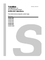
SERVICE MANUAL
Concealed microcomputer control type
Model name:
VN-M150HE
VN-M250HE
VN-M350HE
VN-M500HE
VN-M650HE
VN-M800HE
VN-M1000HE
+00A10-021_01EN.book
Page 1
Friday, March 11, 2011
7:28 PM
Contents
1 Features . . . . . . . . . . . . . . . . . . . . . . . . . . . . . . . . . . . . . . . . . . . . . . . . . . . . . . . . . . . . 10
2 Specifications . . . . . . . . . . . . . . . . . . . . . . . . . . . . . . . . . . . . . . . . . . . . . . . . . . . . . . . 11
3 Model List . . . . . . . . . . . . . . . . . . . . . . . . . . . . . . . . . . . . . . . . . . . . . . . . . . . . . . . . . . . 14
4 Connection diagram . . . . . . . . . . . . . . . . . . . . . . . . . . . . . . . . . . . . . . . . . . . . . . . . . . 15
5 Parts Rating . . . . . . . . . . . . . . . . . . . . . . . . . . . . . . . . . . . . . . . . . . . . . . . . . . . . . . . . . 16
6 Control Outline. . . . . . . . . . . . . . . . . . . . . . . . . . . . . . . . . . . . . . . . . . . . . . . . . . . . . . . 17
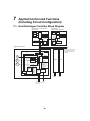
7 Applied Control and Functions (Including Circuit Configuration) . . . . . . . . . . . . . 28
8 Air to Air Heat Exchanger Unit and Air-Conditioning System. . . . . . . . . . . . . . . . . 37
9 Failure Diagnosis. . . . . . . . . . . . . . . . . . . . . . . . . . . . . . . . . . . . . . . . . . . . . . . . . . . . . 44
10 Exchanging and Assembling the Main Components . . . . . . . . . . . . . . . . . . . . . . . . 51
11 Owner’s Manual . . . . . . . . . . . . . . . . . . . . . . . . . . . . . . . . . . . . . . . . . . . . . . . . . . . . . . 63
12 Installation Manual . . . . . . . . . . . . . . . . . . . . . . . . . . . . . . . . . . . . . . . . . . . . . . . . . . . 91
13 How to replace the PC board for service on the Air to Air Heat Exchanger . . . . 139
14 Exploded Diagram/Parts List . . . . . . . . . . . . . . . . . . . . . . . . . . . . . . . . . . . . . . . . . . 143
1
+00A10-021_01EN.book
Page 2
Friday, March 11, 2011
7:28 PM
Original instruction
Please read carefully through these instructions that contain important information which complies with the
“Machinery” Directive (Directive 2006/42/EC), and ensure that you understand them.
Some of the details provided in these instructions differ from the service manual, and the instructions provided here
take precedence.
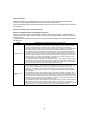
Generic Denomination: Air to Air Heat Exchanger
Definition of Qualified Installer or Qualified Service Person
The Air to Air Heat Exchanger must be installed, maintained, repaired and removed by a qualified installer or
qualified service person. When any of these jobs is to be done, ask a qualified installer or qualified service person
to do them for you.
A qualified installer or qualified service person is an agent who has the qualifications and knowledge described in
the table below.
Agent
Qualifications and knowledge which the agent must have
Qualified installer
• The qualified installer is a person who installs, maintains, relocates and removes the Air to Air Heat
Exchanger made by Toshiba Carrier Corporation. He or she has been trained to install, maintain,
relocate and remove the Air to Air Heat Exchanger made by Toshiba Carrier Corporation or,
alternatively, he or she has been instructed in such operations by an individual or individuals who have
been trained and is thus thoroughly acquainted with the knowledge related to these operations.
• The qualified installer who is allowed to do the electrical work involved in installation, relocation and
removal has the qualifications pertaining to this electrical work as stipulated by the local laws and
regulations, and he or she is a person who has been trained in matters relating to electrical work on
the Air to Air Heat Exchanger made by Toshiba Carrier Corporation or, alternatively, he or she has
been instructed in such matters by an individual or individuals who have been trained and is thus
thoroughly acquainted with the knowledge related to this work.
• The qualified installer who is allowed to work at heights has been trained in matters relating to working
at heights with the Air to Air Heat Exchanger made by Toshiba Carrier Corporation or, alternatively,
he or she has been instructed in such matters by an individual or individuals who have been trained
and is thus thoroughly acquainted with the knowledge related to this work.
Qualified service
person
• The qualified service person is a person who installs, repairs, maintains, relocates and removes the
Air to Air Heat Exchanger made by Toshiba Carrier Corporation. He or she has been trained to install,
repair, maintain, relocate and remove the Air to Air Heat Exchanger made by Toshiba Carrier
Corporation or, alternatively, he or she has been instructed in such operations by an individual or
individuals who have been trained and is thus thoroughly acquainted with the knowledge related to
these operations.
• The qualified service person who is allowed to do the electrical work involved in installation, repair,
relocation and removal has the qualifications pertaining to this electrical work as stipulated by the local
laws and regulations, and he or she is a person who has been trained in matters relating to electrical
work on the Air to Air Heat Exchanger made by Toshiba Carrier Corporation or, alternatively, he or she
has been instructed in such matters by an individual or individuals who have been trained and is thus
thoroughly acquainted with the knowledge related to this work.
• The qualified service person who is allowed to work at heights has been trained in matters relating to
working at heights with the Air to Air Heat Exchanger made by Toshiba Carrier Corporation or,
alternatively, he or she has been instructed in such matters by an individual or individuals who have
been trained and is thus thoroughly acquainted with the knowledge related to this work.
2
+00A10-021_01EN.book
Page 3
Friday, March 11, 2011
7:28 PM
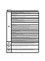
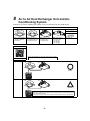
Definition of Protective Gear
When the Air to Air Heat Exchanger is to be transported, installed, maintained, repaired or removed, wear
protective gloves and ‘safety’ work clothing.
In addition to such normal protective gear, wear the protective gear described below when undertaking the special
work detailed in the table below.
Failure to wear the proper protective gear is dangerous because you will be more susceptible to injury, burns,
electric shocks and other injuries.
Work undertaken
Protective gear worn
All types of work
Protective gloves
‘Safety’ working clothing
Electrical-related work
Gloves to provide protection for electricians and from heat
Work done at heights
(50 cm or more)
Helmets for use in industry
Transportation of heavy objects
Shoes with additional protective toe cap
The important contents concerned to the safety are described on the product itself and on this Service Manual.
Please read this Service Manual after understanding the described items thoroughly in the following contents
(Indications/Illustrated marks), and keep them.
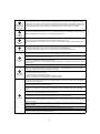
[Explanation of indications]
Indication
Explanation
DANGER
Indicates contents assumed that an imminent danger causing a death or serious injury of the repair
engineers and the third parties when an incorrect work has been executed.
WARNING
Indicates possibilities assumed that a danger causing a death or serious injury of the repair
engineers, the third parties, and the users due to troubles of the product after work when an incorrect
work has been executed.
CAUTION
Indicates contents assumed that an injury or property damage (*) may be caused on the repair
engineers, the third parties, and the users due to troubles of the product after work when an incorrect
work has been executed.
* Property damage: Enlarged damage concerned to property, furniture, and domestic animal/pet
[Explanation of illustrated marks]
Mark
Explanation
Indicates prohibited items (Forbidden items to do)
The sentences near an illustrated mark describe the concrete prohibited contents.
Indicates mandatory items (Compulsory items to do)
The sentences near an illustrated mark describe the concrete mandatory contents.
Indicates cautions (Including danger/warning)
The sentences or illustration near or in an illustrated mark describe the concrete cautious contents.
3
+00A10-021_01EN.book
Page 4
Friday, March 11, 2011
7:28 PM
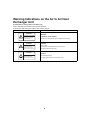
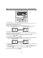
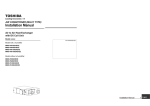
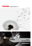
Warning Indications on the Air to Air Heat
Exchanger Unit
[Confirmation of warning label on the main unit]
Confirm that labels are indicated on the specified positions.
If removing the label during parts replace, stick it as the original.
Warning indication
WARNING
Description
WARNING
ELECTRICAL SHOCK HAZARD
Disconnect all remote
electric power supplies
before servicing.
WARNING
Moving parts.
Do not operate unit with
inspection cover removed.
Stop the unit before the servicing.
CAUTION
High temperature parts.
You might get burned
when removing this cover.
ELECTRICAL SHOCK HAZARD
Disconnect all remote electric power supplies before servicing.
WARNING
Moving parts.
Do not operate unit with inspection cover removed.
Stop the unit before the servicing.
CAUTION
High temperature parts.
You might get burned when removing this cover.
4
+00A10-021_01EN.book
Page 5
Friday, March 11, 2011
7:28 PM
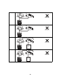
Precautions for Safety
The manufacturer shall not assume any liability for the damage caused by not observing the description of this
manual.
DANGER
Before carrying out the installation, maintenance, repair or removal work, be sure to set the circuit breaker for Air
to Air Heat Exchanger to the OFF position. Otherwise, electric shocks may result.
Before opening the electrical control cover or inspection cover of the Air to Air Heat Exchanger, set the circuit
breaker to the OFF position.
Failure to set the circuit breaker to the OFF position may result in electric shocks through contact with the interior
parts.
Only a qualified installer (*1) or qualified service person (*1) is allowed to remove the electrical control cover or
inspection cover of the Air to Air Heat Exchanger and do the work required.
When cleaning the filter or heat exchange element of the Air to Air Heat Exchanger, set the circuit breaker to OFF
Turn off breaker. without fail, and place a “Work in progress” sign near the circuit breaker before proceeding with the work.
When you have noticed that some kind of trouble (such as when an error display has appeared, there is a smell of
burning, abnormal sounds are heard, water is leaking) has occurred in the Air to Air Heat Exchanger, do not touch
the Air to Air Heat Exchanger yourself but set the circuit breaker to the OFF position, and contact a qualified service
person. Take steps to ensure that the power will not be turned on (by marking “out of service” near the circuit
breaker, for instance) until qualified service person arrives. Continuing to use the Air to Air Heat Exchanger in the
trouble status may cause mechanical problems to escalate or result in electric shocks or other failure.
Electric shock
hazard
When you access inside of the electrical control cover to repair electric parts, wait for about five minutes after
turning off the breaker. Do not start repairing immediately.Otherwise you may get electric shock by touching
terminals of high-voltage capacitors. Natural discharge of the capacitor takes about five minutes.
Place a “Work in progress” sign near the circuit breaker while the installation, maintenance, repair or removal work
is being carried out.
There is a danger of electric shocks if the circuit breaker is set to ON by mistake.
Prohibition
Stay on
protection
Before operating the Air to Air Heat Exchanger after having completed the work, check that the electrical control
cover and inspection cover are closed, and set the circuit breaker to the ON position. You may receive an electric
shock if the power is turned on without first conducting these checks.
If, in the course of carrying out repairs, it becomes absolutely necessary to check out the electrical parts with the
electrical control cover and inspection cover removed in order to find out exactly where the trouble lies, wear
insulated heat-resistant gloves, insulated boots and insulated work overalls, and take care to avoid touching any
live parts.
You may receive an electric shock if you fail to heed this warning. Only qualified service person (*1) is allowed to
do this kind of work.
5
+00A10-021_01EN.book
Page 6
Friday, March 11, 2011
7:28 PM
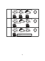
WARNING
Before starting to repair the Air to Air Heat Exchanger, read carefully through the Service Manual, and repair the
Air to Air Heat Exchanger by following its instructions.
Only qualified service person (*1) is allowed to repair the Air to Air Heat Exchanger.
Repair of the Air to Air Heat Exchanger by unqualified person may give rise to a fire, electric shocks, injury, water
leaks and/or other problems.
Only a qualified installer (*1) or qualified service person (*1) is allowed to carry out the electrical work of the Air to
Air Heat Exchanger.
Under no circumstances must this work be done by an unqualified individual since failure to carry out the work
properly may result in electric shocks and/or electrical leaks.
Wear protective gloves and safety work clothing during installation, servicing and removal.
When repairing the electrical parts or undertaking other electrical jobs, wear gloves to provide protection for
electricians and from heat.
Failure to wear this protective gear may result in burn.
Electrical wiring work shall be conducted according to law and regulation in the community and installation manual.
Failure to do so may result in electrocution or short circuit.
Only a qualified installer (*1) or qualified service person (*1) is allowed to undertake work at heights using a stand
of 50 cm or more or to remove the electrical control cover or inspection cover of the Air to Air Heat Exchanger to
undertake work.
When working at heights, use a ladder which complies with the ISO 14122 standard, and follow the procedure in
the ladder’s instructions.
Also wear a helmet for use in industry as protective gear to undertake the work.
General
When working at heights, put a sign in place so that no-one will approach the work location, before proceeding with
the work.
Parts and other objects may fall from above, possibly injuring a person below.
When executing address setting, test run, or troubleshooting through the checking window on the electric parts box,
put on insulated gloves to provide protection from electric shock. Otherwise you may receive an electric shock.
Use a hand track or forklift to carry the unit. When carrying it by human power, have four persons or more;
otherwise, you may strain your back.
When transporting the Air to Air Heat Exchanger, wear shoes with protective toe caps, protective gloves and other
protective clothing.
When transporting the Air to Air Heat Exchanger, do not take hold of the bands around the packing carton.
You may injure yourself if the bands should break.
Use wiring that meets the specifications in the Installation Manual and the stipulations in the local regulations and
laws. Use of wiring which does not meet the specifications may give rise to electric shocks, electrical leakage,
smoking and/or a fire.
Exchange to parts specified in service manual, which meet the specification or listed in parts list of service manual.
Failure to use specified parts may result in electrical shock, smoke, and/or fire.
Confirm whether there is a risk of the Air to Air Heat Exchanger falling down during maintenance or repairing work.
Inspect the Air to Air Heat Exchanger unit for any falling hazard of the unit before maintenance or repair.
Before you open the Supply/Exhaust air grill, set the circuit breaker to the OFF position. Otherwise, your hand may
be caught in the rotating parts inside and an injury may result.
After completing the repair or relocation work, check that the earth wires are connected properly.
Check earth
wires.
Prohibition of
modification.
Use specified
parts.
Be sure to connect earth wire. (Grounding work) Incomplete earthing causes an electric shock.
Do not connect earth wires to gas pipes, water pipes, and lightning rods or earth wires for telephone wires.
Do not modify the products. Do not also disassemble or modify the parts.
It may cause a fire, electric shock or injury.
When any of the electrical parts are to be replaced, ensure that the replacement parts satisfy the specifications
given in the Service Manual (or use the parts contained on the parts list in the Service Manual).
Use of any parts which do not satisfy the required specifications may give rise to electric shocks, smoking and/or
a fire.
6
+00A10-021_01EN.book
Page 7
Friday, March 11, 2011
7:28 PM
If, in the course of carrying out repairs, it becomes absolutely necessary to check out the electrical parts with the
electrical control cover of one or more of the Air to Air Heat Exchanger removed in order to find out exactly where
Do not bring a the trouble lies, put a sign in place so that no-one will approach the work location before proceeding with the work.
child close to the Third-party individuals may enter the work site and receive electric shocks if this warning is not heeded.
equipment.
Insulating
measures
Assembly/
Wiring
Insulator check
Connect the cut-off lead wires with crimp contact, etc., put the closed end side upward and then apply a water-cut
method, otherwise a leak or production of fire is caused at the users’ side.
After repair work, surely assemble the disassembled parts, and connect and lead the removed wires as before.
Perform the work so that the electrical control cover does not catch the inner wires.
If incorrect assembly or incorrect wire connection was done, a disaster such as a leak or fire is caused at user’s
side.
After the work has finished, be sure to use an insulation tester set (500V Megger) to check the resistance is 1MΩ
or more between the charge section and the non-charge metal section (Earth position).
If the resistance value is low, a disaster such as a leak or electric shock is caused at user’s side.
Once the repair work has been completed, check for the insulation resistance.
Then perform a trial run to check that the Air to Air Heat Exchanger is running properly.
After repair work has finished, check there is no trouble. If check is not executed, a fire, electric shock or injury may
be caused. For a check, turn off the power breaker.
Check after
repair
After repair work (installation of electrical control cover and inspection cover) has finished, execute a test run to
check there is no generation of smoke or abnormal sound.
If check is not executed, a fire or an electric shock is caused. Before test run, install the electrical control cover and
inspection cover.
Be sure to fix the screws back which have been removed for installation or other purposes.
Only a qualified installer (*1) or qualified service person (*1) is allowed to relocate the Air to Air Heat Exchanger. It
is dangerous for the Air to Air Heat Exchanger to be relocated by an unqualified individual since a fire, electric
shocks, injury, water leakage, noise and/or vibration may result.
Check after
reinstallation
Check the following items after reinstallation.
1) The earth wire is correctly connected.
2) The power cord is not caught in the product.
3) There is no inclination or unsteadiness and the installation is stable.
If check is not executed, a fire, an electric shock or an injury is caused.
Only a qualified installer (*1) or qualified service person (*1) is allowed to install the Air to Air Heat Exchanger. If
the Air to Air Heat Exchanger is installed by an unqualified individual, a fire, electric shocks, injury, water leakage,
noise and/or vibration may result.
Before starting to install the Air to Air Heat Exchanger, read carefully through the Installation Manual, and follow its
instructions to install the Air to Air Heat Exchanger.
Be sure to use the company-specified products for the separately purchased parts. Use of non-specified products
may result in fire, electric shock, water leakage or other failure. Have the installation performed by a qualified
installer.
Do not supply power from the power terminal block equipped on the outdoor unit to another outdoor unit. Capacity
overflow may occur on the terminal block and may result in fire.
Do not install the Air to Air Heat Exchanger in a location that may be subject to a risk of expire to a combustible gas.
If a combustible gas leaks and becomes concentrated around the unit, a fire may occur.
Installation
Install the Air to Air Heat Exchanger at least 2.5 m above the floor level since otherwise the users may injure
themselves or receive electric shocks if they poke their fingers or other objects into the Air to Air Heat Exchanger
while the it is running.
Install a circuit breaker that meets the specifications in the installation manual and the stipulations in the local
regulations and laws.
Install the circuit breaker where it can be easily accessed by agent.
When installing a circuit breaker outdoors, install one which is designed to be used outdoors.
Do not place any combustion appliance in a place where it is directly exposed to the wind of Air to Air Heat
Exchanger, otherwise it may cause imperfect combustion.
7
+00A10-021_01EN.book
Page 8
Friday, March 11, 2011
7:28 PM
Relocation
• Only a qualified installer (*1) or qualified service person (*1) is allowed to relocate the Air to Air Heat Exchanger.
It is dangerous for the Air to Air Heat Exchanger to be relocated by an unqualified individual since a fire, electric
shocks, injury, water leakage, noise and/or vibration may result.
(*1) Refer to the “Definition of Qualified Installer or Qualified Service Person.”
8
+00A10-021_01EN.book
Page 9
Friday, March 11, 2011
7:28 PM
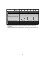
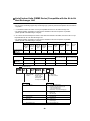
Specifications
Model
Sound power level (dBA)
Weight (kg)
VN-M150HE, M250HE
*
36
VN-M350HE
*
38
VN-M500HE, M650HE
*
53
VN-M800HE, M1000HE
*
70
* Under 70 dBA
Declaration of Incorporation
of Partly Completed Machinery
Manufacturer:
Toshiba Carrier Corporation
336 Tadehara, Fuji-shi, Shizuoka-ken 416-8521 JAPAN
Representative/
TCF holder:
Toshiba Carrier UK Ltd.
Porsham Close, Belliver Industrial Estate,
PLYMOUTH, Devon, PL6 7DB.
United Kingdom
Hereby declares that the machinery described below:
Generic Denomination: Air to Air Heat Exchanger
Model/type:
VN-M150HE
VN-M250HE
VN-M350HE
VN-M500HE
VN-M650HE
VN-M800HE
VN-M1000HE
Commercial name:
TOSHIBA Air to Air Heat Exchanger
Complies with the provisions of the “Machinery” Directive (Directive 2006/42/EC) and the regulations transposing
into national law.
Must not be put into service until the final machinery into which it is to be incorporated has been declared in
conformity with the provisions of Machinery Directive, where appropriate.
NOTE
This declaration becomes invalid if technical or operational modifications are introduced without the manufacturer’s
consent.
9
+00A10-021_01EN.book
1
Page 10
Friday, March 11, 2011
7:28 PM
Features
Main features
The ventilation balance of air supplying and air
exhausting can be changed.
The filter inspection display function calculates the total
running time and prompts you through the remote
controller to inspect the filter.
The cold mode function automatically makes the air
supplying motor run intermittently when the outdoor air
temperature is -10°C or lower.
The timer function allows you to set the unit to start/
stop operation at the specified time.
The separately sold central controller enables central
control of 128 groups.
The separately sold wired remote controller enables
group operation control of up to 8 units.
The unit can operate in cooperation with an airconditioner (SMMS series, DI/SDI series).
◆ Power saving ventilation
The cost of cooling and heating is reduced thanks to
the unit efficiently retrieving thermal energy (outdoor
air load) which has been lost during ordinary
ventilation.
◆ Space saving
Significant reduction of outdoor air load and the ability
to retrieve thermal energy enable the production of
smaller air conditioning devices.
◆ Humidity control
When cooling, highly humid outdoor air is conditioned
to near the humidity of the dehumidified (cooled) indoor
air before being supplied.
When heating, moisture from the return air is
transferred to the dry outdoor air before the outdoor air
is supplied.
About ventilation modes
The unit has three ventilation modes.
• Heat exchange mode
Exchanging heat between the outdoor air and return
air and making the temperature and humidity of the
outdoor air closer to those of the return air before
supplying it.
• Bypass mode
Outdoor air is taken into a room as it is. This mode is
mainly used in spring and summer.
• Automatic mode
1. For an Air to Air Heat Exchanger system
The heat exchange mode and the bypass mode are
automatically switched between following the
information from the return air and outdoor air
temperature sensors in the unit.
2. For an Air to Air Heat Exchanger system linked with
air conditioners
The heat exchange mode and the bypass mode are
automatically switched between depending on the
operation status of the air conditioner (cooling,
heating, dry, fan, or temperature setting) and the
information from the return air and outdoor air
temperature sensors in the unit.
◆ Comfortable ventilation
Ventilation without big changes in temperature is
realized.
In addition, stable ventilation is possible even in an air
tight room due to simultaneous air intake and
expulsion.
◆ Sound insulation
Air trunks and heat exchange elements provide sound
insulation.
They reduce the incoming of outdoor noise and the
outward flow of sounds indoor and help keep the office
or shop, and their surroundings quiet.
◆ Easy installation
The linear air supplying/exhausting method enables
simple design and installation.
Inverted installation is possible and only one inspection
slot is required for two units.
A complete inspection is possible through a single
inspection slot.
CAUTION
If the outdoor air temperature becomes about to 15°C or
less in [Automatic mode] or [Bypass mode], the system
will automatically start to run in [Heat exchange mode]
regardless of the mode setting to prevent condensation
in the Air to Air Heat Exchanger.
* The indication of the ventilation mode setting does not
change.
◆ Other
The filter has excellent dust filtering performance
(mass spectrometry 82%).
The air volume can be switched between Extra High
and High.
10
+00A10-021_01EN.book
2
Page 11
Friday, March 11, 2011
7:28 PM
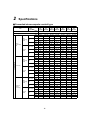
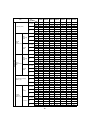
Specifications
Concealed microcomputer control type
Model No.
Item
Fan Speed
VNM150HE
VNM250HE
VNM350HE
Type
VNM650HE
VNM800HE
VNM1000HE
Concealed type
Power Supply (V)
Single phase 220-240V~,50Hz 220V~,60Hz
(Extra high)
Heat
Exchange High
Mode
Low
Power
consumption
(W)
(Extra high)
Bypass
Mode
High
Low
(Extra high)
Heat
Exchange High
Mode
Characteristics
VNM500HE
Low
Current (A)
(Extra high)
Bypass
Mode
High
Low
(Extra high)
Heat
Exchange High
Mode
Low
Maximum
running
Current (A)
(Extra high)
Bypass
Mode
High
Low
50Hz
68-78
123-138
165-182
214-238
262-290
360-383
532-569
60Hz
76
131
209
260
307
446
622
50Hz
59-67
99-111
135-145
176-192
240-258
339-353
494-538
60Hz
65
105
162
206
283
408
589
50Hz
42-47
52-59
82-88
128-142
178-191
286-300
353-370
60Hz
45
54
94
144
206
333
411
50Hz
68-78
123-138
165-182
214-238
262-290
360-383
532-569
60Hz
76
131
209
260
307
446
622
50Hz
59-67
99-111
135-145
176-192
240-258
339-353
494-538
60Hz
65
105
162
206
283
408
589
50Hz
42-47
52-59
82-88
128-142
178-191
286-300
353-370
60Hz
45
54
94
144
206
333
411
50Hz
0.31-0.33
0.58-0.61
0.76-0.76
0.99-1.00
1.25-1.30
1.67-1.63
2.47-2.46
60Hz
0.36
0.60
0.99
1.20
1.40
2.03
2.84
50Hz
0.27-0.28
0.47-0.49
0.62-0.61
0.81-0.81
1.14-1.13
1.57-1.50
2.31-2.28
60Hz
0.28
0.49
0.74
0.94
1.30
1.85
2.69
50Hz
0.20-0.20
0.25-0.26
0.38-0.37
0.59-0.60
1.25-1.30
1.31-1.27
1.62-1.57
60Hz
0.20
0.25
0.43
0.66
0.95
1.52
1.87
50Hz
0.32-0.33
0.61-0.65
0.81-0.82
1.19-1.23
1.37-1.41
2.15-2.23
2.89-2.94
60Hz
0.36
0.65
1.09
1.38
1.59
2.40
3.37
50Hz
0.27-0.28
0.46-0.49
0.61-0.62
0.87-0.91
1.17-1.20
1.84-1.94
2.57-2.61
60Hz
0.30
0.47
0.73
0.96
1.34
2.01
2.95
50Hz
0.20-0.21
0.25-0.26
0.42-0.44
0.64-0.68
0.90-0.95
1.49-1.58
1.85-1.87
60Hz
0.21
0.25
0.45
0.68
0.98
1.59
1.96
50Hz
0.32-0.33
0.61-0.65
0.81-0.82
1.19-1.23
1.37-1.41
2.15-2.23
2.89-2.94
60Hz
0.36
0.65
1.09
1.38
1.59
2.40
3.37
50Hz
0.27-0.28
0.46-0.49
0.61-0.62
0.87-0.91
1.17-1.20
1.84-1.94
2.57-2.61
60Hz
0.30
0.47
0.73
0.96
1.34
2.01
2.95
50Hz
0.20-0.21
0.25-0.26
0.42-0.44
0.64-0.68
0.90-0.95
1.49-1.58
1.85-1.87
60Hz
0.21
0.25
0.45
0.68
0.98
1.59
1.96
11
+00A10-021_01EN.book
Page 12
Friday, March 11, 2011
7:28 PM
Model No.
VNM150HE
VNM250HE
VNM350HE
VNM500HE
VNM650HE
VNM800HE
VNM1000HE
50Hz
150
250
350
500
650
800
1000
60Hz
150
250
350
500
650
800
1000
50Hz
150
250
350
500
650
800
1000
60Hz
150
250
350
500
650
800
1000
50Hz
110
155
210
390
520
700
755
60Hz
110
155
210
390
520
700
755
50Hz
82-102
80-98
114-125
134-150
91-107
142-158
130-150
60Hz
99
97
167
181
134
171
185
50Hz
52-78
34-65
56-83
69-99
58-82
102-132
97-122
60Hz
59
38
33
63
68
102
120
50Hz
47-64
28-40
65-94
62-92
61-96
76-112
84-127
60Hz
46
22
39
44
52
58
55
50Hz
82-102
80-98
114-125
134-150
91-107
142-158
130-150
60Hz
99
97
167
181
134
171
185
50Hz
52-78
34-65
56-83
69-99
58-82
102-132
97-122
60Hz
59
38
33
63
68
102
120
50Hz
47-64
28-40
65-94
62-92
61-96
76-112
84-127
60Hz
46
22
39
44
52
58
55
50Hz
26.0-28.0
29.5-30.0
34.0-35.0
32.5-34.0
34.0-36.0
37.0-38.5
39.5-40.5
60Hz
27.5
31.5
35.5
33.5
35.5
38
41.5
50Hz
24.0-25.5
25.0-27.0
30.0-32.0
29.5-31.0
33.0-34.0
35.5-37.0
38.5-40.0
60Hz
24.5
25
29.5
29
34
35
39
50Hz
20.0-22.0
21.0-22.0
27.0-29.0
26.0-29.0
31.0-32.5
33.5-35.0
34.0-35.5
60Hz
20
21
23.5
24.5
29.5
32.5
33.5
50Hz
81.5
78
74.5
76.5
75
76.5
73.5
60Hz
81.5
78
74.5
76.5
75
76.5
73.5
50Hz
81.5
78
74.5
76.5
75
76.5
73.5
60Hz
81.5
78
74.5
76.5
75
76.5
73.5
50Hz
83
81.5
79.5
78
76.5
77.5
77
60Hz
83
81.5
79.5
78
76.5
77.5
77
50Hz
74.5
70
65
72
69.5
71
68.5
60Hz
74.5
70
65
72
69.5
71
68.5
50Hz
74.5
70
65
72
69.5
71
68.5
60Hz
74.5
70
65
72
69.5
71
68.5
50Hz
76
74
71.5
73.5
71.5
71.5
71.5
60Hz
76
74
71.5
73.5
71.5
71.5
71.5
50Hz
69.5
65
60.5
64.5
61.5
64
60.5
60Hz
69.5
65
60.5
64.5
61.5
64
60.5
50Hz
69.5
65
60.5
64.5
61.5
64
60.5
60Hz
69.5
65
60.5
64.5
61.5
64
60.5
50Hz
71
69
67
66.5
64
65.5
64.5
60Hz
71
69
67
66.5
64
65.5
64.5
Item
Fan Speed
(Extra high)
Air Volume (m3/h)
High
Low
(Extra high)
Heat
Exchange High
Mode
Low
External
Static
Pressure (Pa)
(Extra high)
Bypass
Mode
High
Low
(Extra high)
Characteristics
Heat
Exchange High
Mode
Low
Sound
pressure level
(dB)
(Extra high)
Bypass
Mode
High
Low
(Extra high)
Temperature Exchange
Efficiency (%)
High
Low
(Extra high)
for
heating
Enthalpy
exchange
Efficiency (%)
High
Low
(Extra high)
for cooling High
Low
12
+00A10-021_01EN.book
Page 13
Friday, March 11, 2011
7:28 PM
Model No.
Item
Fan Speed
VNM150HE
VNM250HE
VNM350HE
Construction
VNM650HE
Frame
Zinc steel sheets
Motor
4-pole capacitor dielectric motor (E type)
Fan
Nonwoven fabric (Collection effect weighing method 82%)
Adapter
Zinc steel sheets
External dimensions (Length x Width x Height)
(mm)
900 x 900 x 290
Product weight (kg)
36
Ø100
1189 x 1189 x 400
53
70
Ø200
Ø250
Ø150
Corrugated board package
1394 x 362 x 932
42
No. of stacked boxes
Accessory
1140 x 1140 x 350
38
Shape
Weight (kg)
VNM1000HE
Special paper + Resin
Filter
Dimensions (Length x Width x Height) (mm)
VNM800HE
PP resin
Heat exchanger
Applicable duct nominal diameter (mm)
Package
VNM500HE
1634 x 422 x 1172
1683 x 472 x 1221
61
79
45
3
Adapter: 4, Screw: 16/24, Installation Manual: 1, Owner’s Manual: 1
* Sound Power Level is less than 70 dBA
* Sound pressure level of the product is the value which was measured at the acoustic room. Actually, in the
established condition, that under go influence by the echoing of the room and so that become bigger than the display
numerical value.
* The power consumption, the current and the exchange efficiency are values at the time of the mentioned air volume.
* Sound pressure level shall be measured 1.5m below the center of the unit.
* The temperature exchange efficiency averages that of when cooling and heating.
13
+00A10-021_01EN.book
3
Page 14
Friday, March 11, 2011
7:28 PM
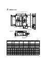
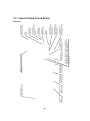
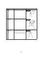
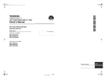
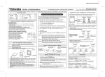
Model List
Damper motor Damper
Heat exchange element (2)
25
D
C
L
RA
(Return air)
EA
(Exhaust air)
Indoor
side
E
A
B
Outdoor
side
SA
(Supply air)
Motor
(Supply Air)
Motor
(Exhaust air)
25
200
C
OA
(Outdoor air)
Electrical control base
M
Hanging bracket (4)
4 - 13 X30 Oval hole
F
G
H
K
Adapter (4)
I
J
Fixed part of
inspection cover
H
Filter (x 2)
Electrical control cover
Inspection cover
High efficiency filter
(One for each element)
(sold separately)
Fixing lever
Unit: mm
Item
Count
Adapter
4
Electrical control cover
1
Inspection cover
1
Material
Remarks
Item
Count
Galvanized steel sheet
Filter
4
Damper
1
Galvanized steel sheet
Damper motor
1
Material
Remarks
Collecting
efficiency (Mass
Spectrometry):
82%
Nonwoven fabric
Motor (Exhaust air)
1
Hanging bracket
4
Galvanized steel sheet
Motor (Supply air)
1
Electrical control base
1
Galvanized steel sheet
Heat exchange
element
2
Fixing lever
1
SUS304
Model name
A
Fire-resistant paper +
Resin
B
C
D
Air to air heat
exchanger
E
F
G
H
I
J
K
L
M
Applicable duct
nominal diameter
VN-M150HE
900
724
88
810
957
900
454
80
Ø98
Ø110
121
290
145
Ø100
VN-M250HE
900
670
115
810
957
900
454
97
Ø145
Ø158
162
290
145
Ø150
VN-M350HE
900
670
115
810
957
900
454
97
Ø145
Ø158
162
290
145
Ø150
VN-M500HE
1140
800
170
1050
1197
1140
454
80
Ø195
—
Ø212
350
175
Ø200
VN-M650HE
1140
800
170
1050
1197
1140
454
80
Ø195
—
Ø212
350
175
Ø200
VN-M800HE
1189
800
195
1099
1246
1189
454
85
Ø245
—
Ø262
400
200
Ø250
VN-M1000HE
1189
800
195
1099
1246
1189
454
85
Ø245
—
Ø262
400
200
Ø250
14
+00A10-021_01EN.book
4
Page 15
Friday, March 11, 2011
7:28 PM
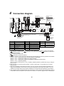
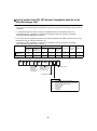
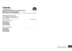
Connection diagram
Gray
M
1~ FM2
Connector
(Black)
43F11
43F22
43F21
8
8
8
8
External output
(220-240V~, under 1A each)
No voltage a-contact input
Red
White
Red
White
1 3
1
F01
T3.15A
250V~
5
(Red)
123456
CN760
1 3
(White)
Indoor control
circuit board
MCC1615
+
-
3
2 3 4
5 TB3
Power
supply
5
Voltage DC (12V, 24V) input
1
2
5
2
9 CN704
7
DC20V
DC12V
DC 5V
CN67
(Black)
12345
CN705
SW301
SW701
ON
ON
OFF
OFF
SW702
SW703
ON
ON
OFF
OFF
1 2 34
1 2 34
CN040
(Blue)
Air to Air Heat
Exchanger
represents the connector to switch between
Extra High and High.
CN105 1
2
t°
TRA
CN106 1
2
t°
TOA
(White)
1
2
3 CN041
1
(Blue)
Black Black
TB2 U3 U4 A
B
Wiring for central control
Power supply for the Air
to Air Heat Exchanger
220-240V~, 50Hz
220V~, 60Hz
Code
1 2
CN706
(Brown)
Blue Blue
R(L) S(N) TB1
Earth
1 Common
2 Remote controller operation
3 Ventilation fan speed
4 Ventilation mode
5 Operation
White
Yellow
Blue
Black
Red
6
1
RY710
5
RY702
3 23 1
43F22
43F21
5
5
1 3
RY705
(White)
CN702
M DAM
RY709
CN701
*5 External input (sold
separately)
Operation output
Common
External damper output
Abnormal/Bypass mode output
RY708
Black
RY704
Blue
Red
3 23 1
43F12
43F11
5
5
White
P01
Connector
(Red *6)
White
Connector
(White *6)
Black
Brown
Blue
Black
Orange
43F12
C
Yellow
White
Red
7
Gray
Yellow
Blue
Light blue
Pink
Brown
C
White
7
Yellow
White
White
7
RY701
M
1~ FM1
Connector
(White)
Light blue
7
Wiring for the remote
controller
A B
Part name
Code
Part name
CN***
Connector
TOA
TOA sensor
F01
Fuse
RY701, RY702
Relay for air supplying motor
FM1
Air supplying motor
RY704, RY705
Relay for air exhausting motor
FM2
Air exhausting motor
TB1
DAM
Damper motor
TB2
Terminal block (power supply)
Terminal block (communication)
TRA
TRA sensor
TB3
Terminal block (external output)
Code
Wired remote
controller (sold
separately)
Part name
SW301, SW701
DIP switch
SW702, SW703
43F11, 43F12
Relay for air supplying motor
43F21, 43F22
Relay for air exhausting motor
1. The dotted line represents a wire procured locally, and the dashed line represents an option sold separately.
2.
represents a terminal block,
represents a connection terminal, and
represents a connector on
the printed circuit board.
3.
represents a protective earth.
4.
represents a printed circuit board.
5. Using a no voltage a-contact input of the external input (sold separately), the following operations are available:
Between 1 and 2: Selecting the remote controller operation (Invalid/Valid)
Between 1 and 3: Adjusting the ventilation fan speed (Low/High)
Between 1 and 4: Selecting the ventilation mode (Bypass mode/Heat exchange mode)
Between 1 and 5: Operation (ON/OFF)
Use a microcurrent contact (DC12V, 1mA). In addition, ON/OFF operation is possible when using a voltage of
DC12V or 24V.
6. Blue wire (High) is connected as factory default. To switch to “Extra High”, connect black wire’s connector
instead of blue.
7. When the temperature of the outdoor air is below -10°C, the unit runs in the cold mode (the ventilator for air
supply runs intermittently). The unit cannot run when the temperature of the outdoor air is below -15°C. The
ventilator for air supply stops running and the ventilator for air exhaust also stops depending on the settings.
8. Even if “Bypass mode” is selected manually, the unit switches to “Heat exchange mode” automatically to prevent
condensation when the temperature of the outdoor air is below 15°C. However, “Bypass mode” is still displayed.
15
+00A10-021_01EN.book
5
Page 16
Friday, March 11, 2011
7:28 PM
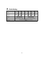
Parts Rating
Model VN-M
Running condenser for supply air
fan motor
Running condenser for exhaust
air fan motor
150HE
250HE
350HE
500HE
650HE
800HE
1000HE
450V
1μF
450V
1μF
450V
3μF
450V
3μF
450V
3μF
450V
5μF
450V
10μF
(5μF x 2)
450V
1μF
450V
1μF
450V
3μF
450V
3μF
450V
3μF
450V
5μF
450V
10μF
(5μF x 2)
TOA sensor
Ø5 size lead wire length:
900mm vinyl tube (Blue)
Ø5 size lead wire length:
1040mm vinyl tube (Blue)
TRA sensor
Ø5 size lead wire length:
1010mm non-migratory tube (Black)
Ø5 size lead wire length:
1270mm non-migratory tube (Black)
Relay
LY-1F
Rated voltage: AC220V/240V Rated load: 10A AC220V
Damper motor
MP24ZN
16
+00A10-021_01EN.book
6
Page 17
Friday, March 11, 2011
7:28 PM
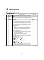
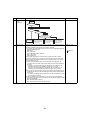
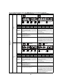
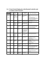
Control Outline
Air to Air Heat Exchanger
Control Specifications
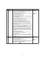
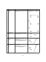
NO.
1
Item
Remarks
When the power 1. If the power supply is reset during the occurrence of an error, the check code is
is reset
cleared.
If an abnormal state continues even after the unit is restarted by pressing the [ON/
OFF] button on the remote controller, the check code is redisplayed on the remote
controller.
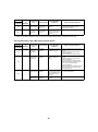
Ventilation
mode control
2
Specification outline
Air to Air Heat Exchanger system and Air to Air Heat Exchanger system linked with
air conditioners
1) Ventilation mode control
• The control method of the automatic mode is different depending on whether
it is an Air to Air Heat Exchanger system or an Air to Air Heat Exchanger
system linked with air conditioners.
• There are three ventilation modes: Automatic, Heat Exchange, and Bypass.
2) When a system without a remote controller or RBC-AMT32E, RBC-AMS41E
remote controller is used:
• The ventilation mode can be changed with CODE No. (DN) [EA] of the DN
setting.
3) Bypass mode control
• If OA RA/10 + 12.5, the system automatically runs in Heat Exchange mode
to prevent condensation. (For details, see the section “Cold Mode Control.”)
• The display on the remote controller remains “Bypass” regardless of the
ventilation mode in actual operation.
• When operation starts in Bypass mode, the Heat Exchange mode is
maintained for three minutes if the state before stop is Heat Exchange mode
(cold mode control).
1. Air to Air Heat Exchanger system
1) Automatic mode control
• One of the following three zones is selected by the TOA and TRA sensors:
Cooling zone, Fan zone, Heating zone
• Automatic ventilation control is performed in the Cooling and Heating zones.
• For the Fan zone, the mode is fixed to Heat Exchange.
• For five minutes after the start of Automatic mode, the Heat Exchange state is
maintained.
• The display on the remote controller remains “Automatic” regardless of the
ventilation mode in actual operation.
2) Criteria for each zone:
[Cooling zone]
OA 24°C or OA 20°C and RA 24°C
[Fan zone]
20°C OA < 24°C and 20°C RA < 24°C
[Heating zone]
Temperature range out of the Cooling and Fan zones
3) Bypass mode condition in automatic ventilation control
[Cooling zone]
RA 26°C and OA 22°C and RA OA + 3°C
[Heating zone]
RA 18°C and RA/10°C + 14.5°C OA 22°C and OA RA + 3°C
• If the system is in an undefined zone when operation starts, the system is
operated in Heat exchange mode. If the state moves to this zone during
operation, the previous state is retained.
17
TOA sensor
TRA sensor
CODE No. (DN)
[EA] [EC]
+00A10-021_01EN.book
NO.
Page 18
Friday, March 11, 2011
7:28 PM
Item
Ventilation
mode control
(continued)
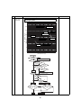
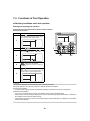
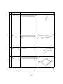
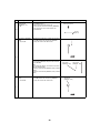
Specification outline
Remarks
Automatic ventilation mode control in the Air to Air Heat
Exchanger system
32
Heat Exchange
28
Cooling zone
24
Bypass
OA: Outdoor Air (°C)
Fan zone
Heat Exchange
20
Bypass
Undefined
zone
Heating zone
16
12
Undefined
zone
Heat Exchange
8
4
12
8
16
20
24
28
RA: Return Air (°C)
2
Start operation
N
Ventilation
mode Automatic
Continue current ventilation mode
Y
Single system
Y
N
DN [EC]
Invalid: 0002
Y
N
N
Air
conditioner
operation
DN [EC]
Y
Valid when stopped:
0001
Y
N
Other than Fan
mode
RA, OA
Y
detection
N
OA 24°C
Automatic ventilation determination
in air-conditioning linkage
N
Y
OA
20°C
N
Y
RA 24°C
N
Y
RA 20°C
Y
Fan zone
Cooling zone
RA 26°C and OA 22°C
RA OA + 3°C
Heating zone
RA 18°C and RA/
10°C + 14.5°C OA 22°C
and OA RA + 3°C
N
Y
Y
Bypass
N
Heat Exchange
18
N
32
+00A10-021_01EN.book
7:28 PM
Item
Ventilation
mode control
(continued)
2
Friday, March 11, 2011
Specification outline
Remarks
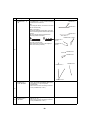
2. Air to Air Heat Exchanger system linked with air conditioners
1) Automatic ventilation mode control in the air-conditioning linkage
• Determine the mode from the operation mode of the air conditioner.
[Cooling zone]: The air conditioner operation mode is Automatic cooling,
Cooling, or Drying mode.
[Heating zone]: The air conditioner operation mode is Automatic heating or
Heating mode.
In Fan mode, the zone is determined by the automatic ventilation mode control
in the Air to Air Heat Exchanger system.
• The setting of the automatic ventilation control in the Air to Air Heat Exchanger
system linked with air conditioners can be changed with CODE No. (DN) [EC]
of the DN setting.
0000: Valid only when the air conditioner is running (factory default). When the
air conditioner is stopped, the zone is determined by the automatic
ventilation mode control of the Air to Air Heat Exchanger system.
0001: Valid even if the air conditioner is stopped. If the air conditioner is
stopped, the zone is determined by the operation mode and set
temperature before stop.
0002: Invalid. The zone is determined by the automatic ventilation mode
control in the Air to Air Heat Exchanger system.
2) The Bypass condition at the time of automatic ventilation mode control in the Air
to Air Heat Exchanger system linked with air conditioners (excluding Fan mode)
[Cooling zone]
RA OA + 3°C and RA set temperature + 2°C and OA RA/10°C + 14.5°C
and RA 20°C
[Heating zone]
OA RA + 3°C and RA set temperature - 2°C and OA RA/10°C + 14.5°C
and RA 27°C
• Condition for returning to Heat Exchange (determined by the set temperature
before stop, even when the air conditioner is stopped)
(For details, see the section “Cold Mode Control.”)
[Cooling zone] RA set temperature - 2°C or RA 18°C
[Heating zone] RA set temperature + 2°C or RA 29°C
• If the system is in an undefined zone when operation starts, the system is
operated in Heat exchange mode. If the state moves to this zone during
operation, the previous state is retained.
Automatic ventilation mode control in the Air to Air Heat
Exchanger system linked with air conditioners
32
Cooling zone
28
24
OA: Outdoor Air (°C)
NO.
Page 19
Bypass
20
Heat Exchange
16
Minimum set
temperature
12
Undefined
zone
8
4
8
12
16
20
RA: Return Air (°C)
19
24
28
32
+00A10-021_01EN.book
NO.
Page 20
Friday, March 11, 2011
7:28 PM
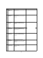
Item
Specification outline
Ventilation
mode control
(continued)
32
Remarks
Heating zone
OA: Outdoor Air (°C)
28
Maximum set
temperature
Bypass
24
Undefined
zone
20
16
Heat Exchange
12
8
2
4
12
8
16
20
24
28
32
RA: Return Air (°C)
Start operation
Automatic ventilation determination in
air conditioning linkage
Cooling or Drying mode
N
Y
Cooling zone
Heating zone
RA, OA
detection
RA, OA
detection
RA OA + 3°C and
RA set temperature + 2°C and
RA OA/10°C + 14.5°C and
RA 20°C
N
N
OA RA + 3°C and
RA set temperature - 2°C and
OA RA/10°C + 14.5°C and
RA 27°C
Y
Y
Bypass
Ventilation fan
speed control
3
Heat Exchange
1. By pressing the [VENT FAN] button, Ventilation Fan Speed High/Low and SA >
EA/SA < EA can be switched.
• SA > EA and SA < EA can be changed with CODE No. (DN) [48] of the DN
setting.
0000: Normal (factory default)
0001: SA (High) > EA (Low) active
0002: SA (Low) < EA (High) active
* “High” may be “Extra High.”
2. When a system without a remote controller or RBC-AMT32E, RBC-AMS41E
remote controller is used:
• The ventilation mode can be changed with CODE No. (DN) [EB] of the DN
setting.
20
CODE No. (DN)
[EB][48]
+00A10-021_01EN.book
NO.
Page 21
Item
7:28 PM
Specification outline
Remarks
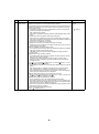
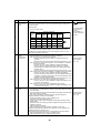
24-hour
ventilation
control
1. 24-hour ventilation operation and setting
CODE No. (DN)
• By operating the [ON/OFF] and [VENT] buttons during operation of Air to Air
[47][31][49][4A]
Heat Exchangers, they stop operation and the system moves to 24-hour
ventilation (low): 60 minutes ON, 60 minutes OFF.
The ventilation mode is fixed to Heat Exchange.
* The setting of 24-hour ventilation (Valid/Invalid) needs to be changed with
• “
” lights up
CODE No. [49] of the DN setting.
0000: Invalid (factory default); 0001: Valid
2. Setting the on/off ratio of 24-hour ventilation
• The on/off ratio complaint response mode can be changed with CODE No. (DN)
[4A] of the DN setting.
0000: Normal; the air volume of ventilation: 1/2, fan is ON for 60 minutes and
OFF for 60 minutes (factory default).
0001–0059: the air volume of ventilation: Fan is ON for [SET DATA of DN]
minutes and OFF for [60-SET DATA of DN] minutes.
3. Changing the ventilation fan speed of 24-hour ventilation
• The setting of the ventilation fan speed of the 24-hour ventilation can be
changed with CODE No. (DN) [47] of the DN setting.
0000: Operate with ventilation fan speed fixed to Low (factory default)
0001: Operate with the ventilation fan speed that was set before stop.
4. In the Air to Air Heat Exchanger system, Air to Air Heat Exchangers stop if the
[ON/OFF] button is pressed when they are running, and the system enters 24hour ventilation mode.
5. In the Air to Air Heat Exchanger system linked with air conditioners, Air to Air Heat
Exchangers and air conditioners stop if the [ON/OFF] button is pressed when they
are running, and the system enters 24-hour ventilation mode.
6. In the Air to Air Heat Exchanger system linked with air conditioners, Air to Air Heat
Exchangers stop if the [VENT] button is pressed when only the Air to Air Heat
Exchangers are running or when both the Air to Air Heat Exchangers and air
conditioners are running, and the system enters 24-hour ventilation mode.
* The setting of the single operation of the Air to Air Heat Exchanger needs to be
changed with CODE No. (DN) [31] of the DN setting. (Setting for the header air
conditioner)
0000: Invalid (factory default); 0001: Valid
7. Operation during 24-hour ventilation
• During 24-hour ventilation, the ventilation fan speed and the ventilation mode
cannot be changed, and they are not displayed.
8. Stop of 24-hour ventilation
• From the NRC-01HE, 24-hour ventilation can be stopped temporarily by holding
the [VENT FAN] button down for four seconds when 24-hour ventilation is in
operation.
• The “
” display goes out.
Delayed
operation
control
1. The delay setting needs to be changed with CODE No. (DN) [4B] of the DN setting CODE No. (DN)
in the Air to Air Heat Exchanger system linked with air conditioners.
[4B]
After pressing the [ON/OFF] button, operation of the Air to Air Heat Exchanger is
delayed by [SET DATA of DN] × 10 minutes.
0000: No delay (factory default)
• “
” lights up.
0001–0006: Delay by [SET DATA of DN] × 10 minutes
* The delay time can be set between 10 and 60 minutes in the unit of 10 minutes.
* If the [VENT] button is pressed during single operation of Air to Air Heat
Exchangers, delayed operation is not performed.
2. During delayed operation, “
” lights up.
4
5
Friday, March 11, 2011
21
+00A10-021_01EN.book
NO.
Page 22
Item
Nighttime heat
purge control
6
Friday, March 11, 2011
7:28 PM
Specification outline
Remarks
This function is valid only for the Air to Air Heat Exchanger system linked with air
CODE No. (DN)
conditioners (invalid for the Air to Air Heat Exchanger system).
[4C][47]
1. If the [ON/OFF] button is pressed during operation, the Air to Air Heat Exchangers
and the air conditioners stop, and the system enters the nighttime heat purge
mode (standby mode).
• “ ” lights up.
* The setting of nighttime heat purge (Valid/Invalid) needs to be changed with
CODE No. (DN) [4C] of the DN setting.
0000: Invalid (factory default)
0001–0048: Temperature monitoring operation starts after [SET DATA of DN] ×
1 hour.
2. Conditions that make the nighttime heat purge setting valid
• Only when the air conditioners and Air to Air Heat Exchangers are stopped
• Only when the operation mode before the stop of the air conditioner header unit
is Automatic cooling, Drying, or Cooling
• When 24-hour ventilation is set to Invalid
• Invalid when only the Air to Air Heat Exchangers are stopped
• Invalid when the air conditioners are stopped in states where only the Air to Air
Heat Exchangers are stopped
3. When the nighttime heat purge setting is valid
• The mode moves from the stop of the Air to Air Heat Exchangers to the nighttime
heat purge operation mode (standby mode).
“ ” lights up, and the system enters the nighttime heat purge operation
standby mode.
4. Nighttime heat purge operating conditions:
• The nighttime heat purge monitoring operation start time specified in the DN
setting (1 to 48 hours) has passed.
• Temperature monitoring operation is performed for five minutes (Heat
Exchange mode) and nighttime heat purge operation starts if the following
conditions are met.
• RA 0A + 3°C and RA set temperature + 2°C and OA RA/10°C + 14.5°C
5. During nighttime heat purge operation
• The ventilation fan speed can be changed with CODE No. (DN) [47] of the DN
setting.
0000: Operate with the ventilation fan speed fixed to Low (factory default)
0001: Operate with the ventilation fan speed that was set before stop
• During nighttime heat purge operation, the ventilation mode (fixed to Bypass
mode) cannot be changed, and it is not displayed.
6. Nighttime heat purge temporary stop condition (one-hour stop)
• RA OA or RA set temperature or OA RA/10°C + 12.5°C or one hour has
passed since the start of nighttime heat purge
7. Nighttime heat purge stop (termination) conditions
• The air conditioners or Air to Air Heat Exchangers start operation.
• When single operation of the fan is performed while “ ” is lit, nighttime heat
purge stops. When single operation of the Air to Air Heat Exchanger is stopped,
the mode does not return to “Nighttime heat purge.”
• 48 hours have passed since the start of nighttime heat purge operation (start of
temperature monitoring operation).
8. When nighttime heat purge operation stops:
• The “ ” display goes out.
22
+00A10-021_01EN.book
NO.
Page 23
Friday, March 11, 2011
7:28 PM
Item
Nighttime heat
purge control
(continued)
Specification outline
Remarks
Nighttime heat purge control
32
Cooling zone
OA: Outdoor Air (°C)
28
24
Bypass
20
Heat Exchange
16
Minimum set
temperature
12
Undefined
zone
8
4
8
12
16
20
24
RA: Return Air (°C)
28
32
Air to Air Heat Exchangers and air conditioners are stopped.
6
24-hour ventilation setting invalid
Y
Air to Air Heat Exchanger system
linked with air conditioners
N
Start 24-hour ventilation
N
Y
Nighttime heat purge setting valid
Set time to start of monitoring operation between
1 and 48 hours
Y
Operation mode before stop
Cooling or Drying mode
N
N
Y
As monitoring operation start time,
1 to 48 hours have passed
N
Y
Monitoring operation (5 minutes of Heat Exchange)
RA
RA OA and + 3°C and
set temperature + 2°C and
OA RA/10°C + 14.5°C
N
Y
Nighttime heat purge operation
RA OA or
RA set temperature or
One hour has passed or
OA RA/10°C + 12.5°C
N
Y
Stop of 1 hour
48 hours have passed since start of
monitoring operation
Y
End of nighttime heat purge
23
N
Remain stopped
+00A10-021_01EN.book
NO.
Page 24
Friday, March 11, 2011
7:28 PM
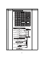
Item
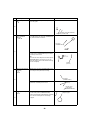
Cold mode
control
Specification outline
Remarks
1. Even in Bypass mode control, the system automatically enters Heat Exchange
CODE No. (DN)
mode to prevent condensation if OA RA/10°C + 12.5°C.
[4D]
• The display on the remote controller remains “Bypass mode” regardless of the
ventilation mode in actual operation.
• When operation starts in Bypass mode, the system runs in Heat Exchange
mode for three minutes if the state before stop is Heat Exchange mode (cold
mode control).
2. The ON time in each zone is maintained for at least three minutes. When the
temperature condition moves to another zone, the system starts the OFF
condition in another zone.
3. In the B zone condition, the supplying fan performs intermittent operation (stops
for 10 minutes and runs for 60 minutes). The exhausting fan runs continuously.
4. In the C zone condition, the supplying fan stops. However, it stops for 60 minutes
and runs for five minutes.
The setting of the exhausting fan can be changed with CODE No. (DN) [4D] of the
DN setting.
0000: Exhausting fan runs (factory default)
0001: Exhausting fan stops
Zone
Zone criterion
Bypass mode permitted zone ⇒ Zone A
OA
RA/10°C + 12.5°C
Zone A ⇒ Zone B
OA
– 10°C or OA
RA – 36°C
Zone B ⇒ Zone C
OA
– 15°C or OA
RA – 41°C
Zone C ⇒ Zone B
OA
– 13°C or OA
RA – 39°C
Zone B ⇒ Zone A
OA
– 8°C or OA
Zone A ⇒ Bypass mode permitted zone
OA
RA/10°C + 14.5°C
RA – 34°C
Cold mode control
20
7
Bypass mode permitted zone
16
Undefined zone
Heat Exchange condition
OA RA/10 + 12.5
OA: Outdoor Air (°C)
12
0
Zone A: Normal operation
(Even in Bypass mode, the mode is
automatically switched to Heat Exchange.)
–4
–8
Undefined zone
Zone B: The supplying fan operates intermittently.
The exhausting fan runs continuously.
–12
Undefined zone
–16
Zone C: The supplying fan operates intermittently.
The exhausting fan operation is set in the DN.
–20
4
8
12
16
20
RA: Return Air (°C)
24
24
28
32
+00A10-021_01EN.book
NO.
Page 25
Friday, March 11, 2011
7:28 PM
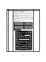
Item
Cold mode
control
(continued)
Specification outline
Remarks
Operating
OA
RA/10°C + 12.5°C
N
Y
Heat Exchange
Zone A?
Y
7
Present ventilation mode continues
N
Zone B?
N
Zone C
Y
DN [4D]
Exhausting fan runs:
0000
Y
Heat Exchange
mode continues
Filter symbol
display
8
Heat Exchange Supplying fan
stops (OFF for 10 minutes and
ON for 60 minutes) Exhausting
fan runs continuously
N
Heat Exchange Supplying fan
stops (OFF for 60 minutes and
ON for 5 minutes) Exhausting
fan runs continuously
Heat Exchange Supplying fan
stops and Exhausting fan
stops (OFF for 60 minutes
and ON for 5 minutes)
1. The indoor header unit’s cumulative hours of operation are counted, and when
CODE No. (DN)
they exceed the prescribed value, a filter replacement signal is sent to the remote [01][02]
controller to display a filter symbol on the remote controller.
• The setting of the prescribed number of hours can be changed with CODE No.
(DN) [01] of the DN setting.
0000: None
• “ ” lights up
0001: 150 hours
0002: 2,500 hours (factory default)
0003: 5,000 hours
0004: 10,000 hours
2. When a filter reset signal is received from the remote controller, the timer
measuring cumulative hours is cleared. If the prescribed number of hours has
been exceeded, the measurement time is reset with the symbol on the remote
controller display erased.
1) In the Air to Air Heat Exchanger system linked with air conditioners, the
cumulative time of operation of the indoor header unit is the representative of
the group.
* In the Air to Air Heat Exchanger system linked with air conditioners, the
cumulative time of 24-hour ventilation operation is not counted.
* In the Air to Air Heat Exchanger system linked with air conditioners, the
cumulative time of the nighttime heat purge operation is not counted.
2) In the Air to Air Heat Exchanger system, the cumulative operating time of the
exhausting fan of the Air to Air Heat Exchanger header unit is the representative
of the group.
* In the Air to Air Heat Exchanger system, the cumulative operating time of 24hour ventilation is counted.
3) When the degree of dirt of the filter is set, its time is half the standard time.
• The setting of the degree of dirt of the filter can be changed with CODE No. (DN)
[02] of the DN setting.
0000: Standard (factory default)
0001: High degree of dirt (half the standard time)
25
+00A10-021_01EN.book
NO.
Page 26
Friday, March 11, 2011
7:28 PM
Item
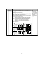
Selection of
central control
mode
Specification outline
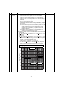
1. The range of operations that can be performed by operating the remote controller • “
” lights up while
of the Air to Air Heat Exchanger can be determined through the setting of the
in central control
central controller.
mode.
2. Setting details
• The display blinks
when a control
• TCC Link central control
function
Operation on NRC-01HE
inaccessible to a
Operation
from TCC
NRC-01HE
remote controller is
Setting
Setting
Setting
Setting
Link central Setting
chosen.
ventilation
ventilation ventilation display
start/stop
timer
control
9
Remarks
start/stop
fan speed mode
Individual
O
O
O
O
O
[Central 1]
×
O
×
O
O
[Central 2]
×
O
×
O
O
[Central 3]
O
O
O
O
O
[Central 4]
O
O
O
O
O
“
” is
displayed
(O: Accessible ×: Inaccessible)
* The ventilation start/stop operation applies only to operation linked with air
conditioners. It becomes effective when “single operation of the fan” is set to
0001 (valid) in CODE No. (DN) [31].
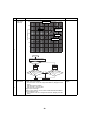
Operation
output
(Connecting an
auxiliary fan)
1. Operation output setting
CODE No. (DN)
• The output setting can be changed by CODE No. (DN) [ED]
[ED]
0000: Contact is on only during normal operation.
* Contact is off during 24-hour ventilation or nighttime heat purge
• External output
operation.
terminal block
* Contact is off during cold mode (while the temperature is below -10 °C).
((1) – (2))
0001: Contact is on during normal operation, 24-hour ventilation, or nighttime
heat purge operation.
* Contact is on when 24-hour ventilation is stopped intermittently.
* Contact is off when nighttime heat purge operation is on standby.
(paused before the monitoring operation of the nighttime heat purge
operation starts)
* Contact is off during cold mode (while the temperature is below -10 °C).
0002: Contact is on during 24-hour ventilation or nighttime heat purge operation.
* Contact is on when 24-hour ventilation is stopped intermittently.
* Contact is off during normal operation or when the nighttime heat purge
operation is on standby. (paused before the monitoring operation of the
nighttime heat purge operation starts)
* Contact is off during cold mode (while the temperature is below -10 °C).
0003: Contact is on only when SA fan (Supplying fan) is running.
* Contact is off when 24-hour ventilation is stopped intermittently, so do
not connect an auxiliary fan.
0004: Contact is on only when EA fan (Exhausting fan) is running.
* Contact is off when 24-hour ventilation is stopped intermittently, so do
not connect an auxiliary fan.
Electric damper
output
1. Output setting for electric damper
CODE No. (DN)
• The setting can be switched between Normal and Complaint Response Setting [5C]
in the DN setting.
• The output setting can be changed with CODE No. (DN) [5C] of the DN setting. • External output
0000: Normal (factory default)
terminal block
0001: 24-hour ventilation, nighttime heat purge operation supported
((3) – (4))
2. Operation ON/OFF condition in normal setting
• ON during intermittent stop in 24-hour ventilation mode
• ON in cold mode control (Zones B and C)
• ON if the fan is stopped when switching the damper (Heat exchange mode/
Bypass mode)
• ON from the start of monitoring operation of nighttime heat purge to the end of
nighttime heat purge
• OFF during delayed operation
• OFF during the stop of normal operation (including 24-hour stop)
3. Operation output ON/OFF condition when support of 24-hour ventilation and
nighttime heat purge operation is set
The settings are the same as those for normal settings except the following:
• OFF during intermittent stop in 24-hour ventilation mode
• OFF during temporary stop in nighttime heat purge mode
10
11
26
+00A10-021_01EN.book
NO.
Page 27
Friday, March 11, 2011
7:28 PM
Item
Specification outline
Remarks
Linked
Connect the Remote ON/OFF adapter (NRB-1HE: sold separately) to the
operation with
connectors CN706(2P) and CN705(5P) on the control circuit board of the Air to Air
external devices Heat Exchanger.
1. Output signals of external devices
• DC12V, DC24V: Connect to CN706(2P)
• No voltage a-contact: Connect to CN705(5P) and use (1) Green – (5) Black
2. Pulse/Static switch of output signals of external devices (Static: OFF by default)
• No. 1 of the switch SW701 on the board (Pulse: ON)
3. Linked operation with external devices
• You can set the Air to Air Heat Exchanger operations for ON/OFF signals of
external devices by CODE No. (DN) [4E].
0000: The Air to Air Heat Exchanger starts/stops together with the starting/
stopping of an external device. (The latter operation of the remote
controller or the switch of the external device overrides the former.)
0001: The Air to Air Heat Exchanger starts together with the starting of an
external device. Use the remote controller to stop operation.
0002: The Air to Air Heat Exchanger stops together with the stopping of an
external device. Use the remote controller to start operation.
Operation signals DN [4E]
12
Mode
External signals: Static
External signals: Pulse
External signal
External signal
ON/OFF
linked Remote control
SW pressed
(0000)
ON
linked
(0001)
OFF
linked
(0002)
Operation ON
status
OFF
Remote control
SW pressed
Operation ON
status
OFF
External signal
External signal
Remote control
SW pressed
Operation ON
status
OFF
Remote control
SW pressed
Operation ON
status
OFF
External signal
External signal
Remote control
SW pressed
Operation ON
status
OFF
Remote control
SW pressed
Operation ON
status
OFF
27
CODE No. (DN)
[4E]
• Remote ON/OFF
adapter (NRB-1HE:
sold separately)
• No. 1 of the switch
SW701 on the board
Pulse: ON
Static: OFF (Factory
setting)
+00A10-021_01EN.book
7
Page 28
Friday, March 11, 2011
7:28 PM
Applied Control and Functions
(Including Circuit Configuration)
7-1. Heat Exchanger Controller Block Diagram
Main (sub) center remote controller
(up to 2 units)
Schedule timer
(when in weekly timer mode)
Display
LCD
Display
LCD
Display
LCD
LCD
driver
Function setting
MCU
Function setting
MCU
Key switch
EEPROM
Key switch
CN2 CN1
DC5V
*1
DC5V
Remote controller
communication circuit
Power
supply
circuit
Rechargeable
battery
Power
supply
circuit
Air1 to Air Heat Exchanger
A
2 A
B
B
3 A
B
Up to 8 units can be connected.
*1 A weekly timer cannot be
connected to a subremote
controller.
EEPROM
Remote controller
communication circuit
DC20V
DC12V
DC5V
TRA sensor
Fan motor
relay circuit
Supplying
fan motor
Fan motor
relay circuit
Exhausting
fan motor
External
output
• Driving
• Damper
• Abnormal/
Bypass
mode
Power
supply circuit
TOA sensor
MCU
Driver
Damper
motor
Same
as left
• Indoor unit
address switching
• Group address
switching
• Central control
address switching
• Pulse/Static
switching
External
input
• Remote
controller
invalid
• Low/High
• Bypass
mode/Heat
Exchange
mode
• Start/Stop
Same
as left
Switch
AC
synchronous
signal input
circuit
R
BUS
communication
circuit
R
S
Power
supply
S
Central
Power supply
220-240V~, 50 Hz control
220V~, 60 Hz
28
R
S
Power
supply
29
Connectors for
the external output
CN704 (white)
Connectors for
the external input
CN706 (white)
Changeover switch for the indoor unit address
Changeover switch for the central control address
Changeover switch for the group address
SW702, SW703
Pulse/Static
changeover switch
Damper motor
CN760 (white), DC12V SW701
Connectors for the
external input
CN705 (red), DC12V
Remote controller
communication LED
D504 (green)
Central control
communication LED
D503 (yellow)
EEPROM
IC503
TRA sensor
CN105 (brown)
TOA sensor
CN106 (white)
Central control
electrical termination
SW301
Central control
CN40 (blue)
CHK
CN71
Remote controller
CN41 (blue), DC20V
Friday, March 11, 2011
Supply air fan
motor
CN701 (white)
Remote controller power source LED
D403 (red)
Page 29
Exhaust air fan
motor
CN702 (red)
Power supply
CN67 (black), AC100V
+00A10-021_01EN.book
7:28 PM
7-2. Indoor Printed Circuit Board
MCC-1615
+00A10-021_01EN.book
Page 30
Friday, March 11, 2011
7:28 PM
7-3. Functions at Test Operation
◆ Checking ventilation mode test operation
Starting and stopping test operation
▼ Performing test operation from the indoor remote controller
Wired remote controller
Procedure
Operation
When the
button is pushed for 4 seconds or
more, “TEST” is displayed in the display section,
and the unit enters test operating mode.
1
2
Press the
button.
By using the
button, select
Errors are detected as usual.
3
or
.
3
4
1, 5
2, 4
When the test operation is finished, push the
button to stop the operation.
(The same display as in procedure 1 appears in
the display.)
Push the
button to clear the test operating
mode.
(“TEST” disappears from the display section, and
the status returns to normal stopped status.)
5
NOTE
Test operation will return to normal operation after a lapse of 60 minutes.
During test operation, the cold mode control and delayed operation are disabled.
Bypass mode ventilation
• In Bypass mode, Bypass operation is performed regardless of the RA and OA sensor temperatures.
Automatic mode ventilation
• In the Air to Air Heat Exchanger system, the ventilation mode is fixed to Heat Exchange.
• If the operation mode is Cooling or Heating in the Air to Air Heat Exchanger system linked with air conditioners,
the ventilation mode is fixed to Heat Exchange.
• If the operation mode is Fan in the Air to Air Heat Exchanger system linked with air conditioners, the ventilation
mode is fixed to Bypass.
30
+00A10-021_01EN.book
Page 31
Friday, March 11, 2011
7:28 PM
◆ Check function for operation of Air to Air Heat Exchanger
This function is provided to check the operation of Air to Air Heat Exchanger singly without communication with the
remote controller. This function can be used regardless of operation or stop of the system.
However, if using this function for a long time, a trouble of the equipment may be caused. Limit using this function
within several minutes.
[How to operate]
Short-circuit CHK pin (CN71 on the P.C. board).
[How to clear]
Open CHK pin. While the system is operating, it stops once but automatically returns to operation after several
minutes.
Short-circuit of CHK pin
Fan motor
(H)
Ventilation mode
Heat exchange mode
Operation output, Electric damper output
OFF
Communication
All ignored
P.C. board LED
Lights
• For the detailed positions of CHK pin (CN71 on P.C. board), refer to the P.C. board MCC-1615.
31
+00A10-021_01EN.book
Page 32
Friday, March 11, 2011
7:28 PM
7-4. Specifications of Optional Connectors on the Air to
Air Heat Exchanger Unit Board
Function
Connector No. Pin No.
External
input
No-voltage
contact a
CN705
2
Remote controller
prohibition input
Remote controller prohibition input (ON: Prohibited, OFF:
Allowed)
3
Ventilation fan speed
change input
Ventilation fan speed change input (ON: LOW, OFF: HIGH)
4
Ventilation mode change
input
Ventilation mode change input (ON: Bypass, OFF: Heat
Exchange)
Start/Stop input
Start/Stop input (pulse/static input changed by No. 1 of DIP
SW701, OFF: Static (default), ON: Pulse)
1
CN706
Note
0V (COM)
5
External
input
DC12V, 24V
Specification
1
2
DC12V (COM)
Start/Stop input
Start/Stop input (pulse/static input changed by No. 1 of DIP
SW701, OFF: Static (default), ON: Pulse)
32
+00A10-021_01EN.book
Page 33
Friday, March 11, 2011
7:28 PM
7-5. Configuring the Function Settings of the Air to Air
Heat Exchanger Unit
(When configuring the settings, use the wired remote controller.)
<Procedure> Stop running the unit before configuring the settings.
1
Press and hold the
or longer.
+
+
buttons for 4 seconds
The Unit No. displayed first indicates the indoor unit address of
the header unit in group control.
The Air to Air Heat Exchanger Unit No. is 31-OO.
The fan of the selected Air to Air Heat Exchanger starts
running.
The
indicator lights up when the wired remote controller
NRC-01HE is used.
• The line (system) address is always 31.
• The indoor unit address is between 1 and 64. The address
is specified with No.1 to No.4 of SW702 and with No.1 and
No.2 of SW703.
2
3
4
5
Each time you press
(left side of the button), the
unit No. of the Air to Air Heat Exchangers in the group
are displayed successively. Only the fan of the selected
Air to Air Heat Exchanger starts running.
Press the temperature
No. (DN).
Press the timer
button to select the CODE
button to select the setting data.
Press the
button. (There are no problems if the
indicator lights up.)
• To change the selected Air to Air Heat Exchanger, return to
2.
• To change CODE No. (DN) to set, return to 3.
6
Press the
button to return to normal operation. (The
unit stops.)
33
3
6
5 14
2
Procedure
1
2
3
4
5
6
End
+00A10-021_01EN.book
Page 34
Friday, March 11, 2011
7:28 PM
Codes (DN codes) for changing settings (Necessary for local advanced control)
The following DN codes are used in common for NRC-01HE, RBC-AMT32E, and RBC-AMS41E.
Code
Description
SET DATA and description
Factory default
Note
01
Lighting-up
hours of the
Filter Sign
0000: None
0001: 150 H
0002: 2500 H
0003: 5000 H
0004: 10000 H
02
Dirty state of
filter
0000: Standard
0000: Standard
0001: High degree of dirt (Half of
standard time)
Adjusting this setting is necessary for the
header unit.
Central control
address
0001-0064: Central address
0099: Unfixed
Adjusting this setting is necessary for the
header unit.
Type code
0050: Air to Air Heat Exchanger 0050: Air to Air Heat
Adjusting this setting is necessary for all
(Ceiling - embedded duct)
Exchanger (Ceiling - the Air to Air Heat Exchangers in the group.
embedded duct)
Capacity code
0000: Unfixed
0001-0007:
Depends on the capacity
Adjusting this setting is necessary for all
the Air to Air Heat Exchangers in the group.
Group address
0099: Unfixed
0000: Individual
0001: Header unit
0002: Follower unit
0099: Unfixed
Does not need to be configured as it is set
in No. 4 of DIPSW703. Can be changed in
the DN setting when No. 4 is OFF.
Auto recovery
from a power
failure
0000: Invalid
0001: Valid
* Resumes the status just
before the power failure
0000: Invalid
*1
03
10
11
14
28
0002: 2500 H
0099: Unfixed
Adjusting this setting is necessary for the
header unit.
Single operation 0000: Invalid
0001: Valid
of the fan
* ON/OFF operation for the Air
to Air Heat Exchanger only
0000: Invalid
31
Adjusting this setting is necessary for the
header unit. (System equipped with the Air
to Air Heat Exchanger and air conditioners)
0000: Always LOW
Adjusting this setting is necessary for all
the Air to Air Heat Exchangers in the group.
47
24-hour
nighttime heat
purge Fan
speed
ventilation
setting
0000: Normal
Adjusting this setting is necessary for all
the Air to Air Heat Exchangers in the group.
48
Imbalanced Fan 0000: Normal
speed
0001: SA (High) > EA (Low)
ventilation
active
0002: SA (Low) < EA (High)
active
* “High” may be “Extra High”.
49
24-hour
ventilation
0000: Invalid
Adjusting this setting is necessary for all
the Air to Air Heat Exchangers in the group.
Adjusting this setting is necessary for all
the Air to Air Heat Exchangers in the group.
4A
ON/OFF ratio of 0000: Normal (The air volume of 0000: Normal
24-hour
ventilation 1/2: 60-minute
ventilation
ON, 60-minute OFF)
0001-0059: Arbitrary ([SET
DATA of DN] minute ON,
[60-SET DATA of DN]
minute OFF)
Delayed
operation
0000: Invalid
0000: Invalid
0001-0006: [SET DATA of DN] x
10 minutes delay
* Delaying the Air to Air Heat
Exchanger operation to
reduce the air-conditioning
load when starting running the
air conditioner
Adjusting this setting is necessary for all
the Air to Air Heat Exchangers in the group.
(System equipped with the Air to Air Heat
Exchanger and air conditioners)
Nighttime heat
purge
0000: Invalid
0001-0048: Start after [SET
DATA of DN] x 1 hour(s)
* Setting for the time before the
nighttime heat purge
operation starts
Adjusting this setting is necessary for all
the Air to Air Heat Exchangers in the group.
(System equipped with the Air to Air Heat
Exchanger and air conditioners)
4B
4C
0000: Always LOW
0001: Fan speed ventilation
before the operation is
stopped
* 24-hour nighttime heat purge
Fan speed ventilation setting
0000: Invalid
0001: Valid
0000: Invalid
34
+00A10-021_01EN.book
Code
4D
4E
Page 35
Friday, March 11, 2011
Description
7:28 PM
SET DATA and description
Factory default
Note
Setting of the
0000: Exhausting fan run
0000: Exhausting fan run
exhausting fan
0001: Exhausting fan stop
operation below * The supplying fan stops when
−15°C (OA)
the temperature is below
−15°C. (OA)
Adjusting this setting is necessary for all
the Air to Air Heat Exchangers in the group.
Setting of the
linked operation
with external
devices
0000: ON/OFF linked
0000: ON/OFF linked
0001: ON linked
0002: OFF linked
* Specifies whether the ON/
OFF operation of the Air to Air
Heat Exchanger is linked with
the external device operation
Adjusting this setting is necessary for the
Air to Air Heat Exchanger to which an
adapter for remote ON/OFF control (sold
separately) is connected.
Damper output
0000: Normal
0001: Support of 24-hour fan,
nighttime heat purge
Adjusting this setting is necessary for the
Air to Air Heat Exchanger which transfers
the operation output.
Start/Stop by
power on/off
0000: Invalid
0000: Invalid
0001: Valid
* Starts/Stops running the Air to
Air Heat Exchanger by
powering on/off.
5C
9D
0000: Normal
Adjusting this setting is necessary for the
header unit. (System equipped with the Air
to Air Heat Exchanger only)
Changing the
0001: Bypass mode
ventilation mode 0002: Heat Exchange mode
0003: Automatic mode
* Compatible with systems
without a remote controller
and RBC-AMT32E, RBCAMS41E
0003: Automatic mode
*1
Changing the
ventilation Fan
speed
0002: High
0003: Low
0004: Imbalanced
* “High” may be “Extra High”.
* Compatible with systems
without a remote controller
and RBC-AMT32E, RBCAMS41E
0002: High
*1
Automatic
ventilation
control in airconditioning
linkage
0000: Valid only when airconditioner is running
0001: Valid even when airconditioner is stopped
0002: Invalid (Control Air to Air
Heat Exchanger only)
* Automatic ventilation control
setting in air-conditioning
linkage
0000: Valid only when airconditioner is
running
Adjusting this setting is necessary for all
the Air to Air Heat Exchangers in the group.
0000: ON during normal
operation
Adjusting this setting is necessary for the
Air to Air Heat Exchanger which transfers
the operation output.
ED
Changing the
0000: ON during normal
operation output
operation
0001: ON during normal
operation, 24-hour
ventilation, or nighttime
heat purge operation
0002: ON during 24-hour
ventilation or nighttime
heat purge operation
0003: ON when SA fan is
running
0004: ON when EA fan is
running
EE
Changing the
0000: ON when an abnormal
abnormal signal/
signal is detected
Bypass mode
0001: ON when the Bypass
signal output
mode signal is detected
0000: ON when an
abnormal signal is
detected
Adjusting this setting is necessary for the
Air to Air Heat Exchanger which transfers
the operation output.
EA
EB
EC
*1 Adjusting this setting is necessary for the header unit when using a system equipped with the Air to Air Heat Exchanger only, and the Air to
Air Heat Exchanger with the smallest indoor unit address number when using a system equipped with the Air to Air Heat Exchanger and air
conditioners.
35
+00A10-021_01EN.book
Page 36
Friday, March 11, 2011
7:28 PM
Capacity of the Air to Air Heat Exchanger
Code: 11
Model
Code: 10
Setting
data
0050*
Setting data
Model name
(abbreviation)
Model
Air to Air Heat Exchanger
(Ceiling-embedded)
VN-M***HE series
Type
0000*
Invalid
0001
150m3/h type
0002
250m3/h type
0003
350m3/h type
0004
500m3/h type
0005
650m3/h type
0006
800m3/h type
0007
1000m3/h type
* Factory default value of EEPROM installed on the service
circuit board
* Factory default value of EEPROM installed on the service
circuit board
Remote controller switch monitoring function
This function is available to call the service monitor mode from the remote controller during a test run to acquire
temperatures of sensors of indoor unit (Air to Air Heat Exchanger).
1
2
3
Push
and
buttons simultaneously for at least 4
seconds to call the service monitor mode.
Pushing TEMP.
buttons, select the number of
sensor (CODE No.) to be monitored. (See the following
table.)
Pushing
(left side of the button), select an indoor
unit to be monitored.
2
* The unit number of the Air to Air Heat Exchanger is 31-OO.
4
Push
button to return to the normal display.
Indoor unit data (Air to Air Heat Exchanger)
CODE No.
Data name
02
Indoor unit Return air temperature (TRA)
F0
Microcomputer cumulative energized hours (x 100h)
F2
Supply air fan cumulative energized hours (x 100h)
F3
Filter cumulative hours (x1 h)
FA
Indoor unit outdoor air temperature (TOA)
36
4
1
3
+00A10-021_01EN.book
8
Page 37
Friday, March 11, 2011
7:28 PM
Air to Air Heat Exchanger Unit and AirConditioning System
Examples of connections available when installing an Air to Air Heat Exchanger unit (VN-M OO HE)
Classified by specifications
Remote controller line
* Adapter omitted
1 Indoor unit compatible 2 Indoor unit not yet
with Air to Air Heat
Exchanger
3 New Air to Air Heat
compatible with Air to
Air Heat Exchanger
Exchanger unit
(VN-M OO HE)
4 Old Air to Air Heat
TCC-LINK line
Exchanger unit
(VN- OO TE)
(VN-1K TAE)
(VN-1K TBE)
Remote controller
Not on the assumption of connection with an Air to Air Heat
Exchanger unit or via general-purpose device interface
NRC-01HE
Pattern 1
1
3
Possible
Pattern 2
2
3
Possible
When a unit not yet compatible with Air to Air Heat Exchange is connected, the ventilation
mode and fan speed cannot be displayed, but the linkage and Air to Air Heat Exchanger stand
alone operations are possible.
Changing the ventilation mode and fan speed is also possible depending on the DN setting.
37
+00A10-021_01EN.book
Pattern 3
Page 38
Friday, March 11, 2011
7:28 PM
1
4
Not Possible
Pattern 4
2
4
Not Possible
Pattern 5
1
4
Not Possible
RC
Pattern 6
2
4
RC
38
Not Possible
+00A10-021_01EN.book
Page 39
Friday, March 11, 2011
7:28 PM
Pattern 7
1
2
3
Possible
Pattern 8
1
3
2
1
3
2
Possible
Pattern 9
When linking a unit compatible with Air to Air Heat Exchange to
one not yet compatible, you need to set a compatible unit as the
group header unit.
39
Possible
+00A10-021_01EN.book
Page 40
Friday, March 11, 2011
7:28 PM
List of Indoor Units (SMMS Series) Compatible with the Air to Air
Heat Exchanger Unit
• “O” in the tables indicates an indoor unit compatible with the Air to Air Heat Exchanger unit.
* For the 4-way air discharge type/2-way air discharge type, products produced in September 2010 or later are
compatible.
• “–” in the tables indicates an indoor unit not yet compatible with the Air to Air Heat Exchanger unit.
* The linkage operation is possible, but changing the ventilation mode and fan speed is not possible.
(Will be possible if the DN setting is changed)
• If “O” is shown but the development number is older than that indicated in the tables, the indoor unit is not yet
compatible with the Air to Air Heat Exchanger unit.
* The linkage operation is possible, but changing the ventilation mode and fan speed is not possible.
(Will be possible if the DN setting is changed)
Indoor unit type
Cassette type
Duct type
4-way air
discharge
type
Compact
4-way air
discharge
type
2-way air
discharge
type
1-way air
discharge
type
Duct type
Built-in
type
Slim duct
type
2
4
2
4
4
4
{
{
{
{
{
{
Development No.
(Series No.)
Compatibility
Indoor unit type
Floor type
Development No.
(Series No.)
Compatibility
Ceiling
type
High wall
type
4
4
4
{
{
–
Floor standing type
Fresh air intake type
4
4
1
{
{
–
Cabinet type
Concealed type
Console type
4
4
{
{
Modular multi type
MM U - AP 009 4
New refrigerant
R410A
H
Guide of capacity
Based on the
cooling capacity
(Btu/h)/1,000
H .......Heat pump
HFE ..Fresh air intake
Development series No.
Type
Note on type
U .........Cassette type
None ...4-way air discharge type
M .........Compact 4-way air discharge type
W.........2-way air discharge type
S..........1-way air discharge type
Y..........Small sized 1-way air discharge type
D .........Duct type
None ...High static pressure type
B..........Built-in type
SP .......Slim duct type
C .........Ceiling type
None ...Ceiling type
K..........High wall type
M .........High wall type
L ..........Floor type
None ...Cabinet type
B..........Concealed type
N .........Console type
F ..........Floor standing type
None ...Floor standing type
40
+00A10-021_01EN.book
Page 41
Friday, March 11, 2011
7:28 PM
List of Indoor Units (DI, SDI Series) Compatible with Air to Air
Heat Exchanger Unit
• “O” in the tables indicates an indoor unit compatible with the Air to Air Heat Exchanger unit.
* For the 4-way air discharge type/Duct type/Slim duct type, products produced in September 2010 or later are
compatible.
• “–” in the tables indicates an indoor unit not yet compatible with the Air to Air Heat Exchanger unit.
* The linkage operation is possible, but changing the ventilation mode and fan speed is not possible.
(Will be possible if the DN setting is changed)
• If “O” is shown but the development number is older than that indicated in the tables, the indoor unit is not yet
compatible with the Air to Air Heat Exchanger unit.
* The linkage operation is possible, but changing the ventilation mode and fan speed is not possible.
(Will be possible if the DN setting is changed)
Indoor unit type
Development No.
(Series No.)
Compatibility
Cassette type
Duct type
4-way air
discharge
type
Compact
4-way air
discharge type
Duct type
Built-in type
Slim duct
type
Ceiling type
High wall
type
Flexi type
4
4
2
4
4
4
4
2
{
{
{
{
{
{
–
–
R A V - S M 140 4
Special mark
SM: Digital
Inverter CD
Common FCU
for DI & SDI
T
Guide of capacity
Based on the cooling
capacity (kw)
Ex.: 140 = 14.0kw
H ...... Heat pump inverter
Development series No.
Note on type
U ......... Cassette type (4-way air discharge)
MU ...... Compact cassette type (4-way air discharge)
D ......... Duct type (High static pressure)
B ......... Built-in duct type
SD....... Slim duct type
C ......... Ceiling type
KR....... Wall type
X ......... Flexi type
41
+00A10-021_01EN.book
Page 42
Friday, March 11, 2011
7:28 PM
Air to Air Heat Exchanger Unit and (SMMS Series) Air-Conditioning System
System
Central control
Address
Air to Air Heat Exchanger only
Linked with air-conditioner
Outdoor
unit
Outdoor
unit
U1 U2
U1 U2
Indoor
unit
A
A
Without
central
control
Air to Air
Heat
Exchanger
and AirConditioner
(SMMS
series)
U1 U2
U1 U2
U1 U2
Indoor
unit
B
Group 1
B
Air to Air Heat
Exchanger
A
A
B
A
B
B
A
B Group 2
A
A
Air-conditioner
remote controller
RBC-AMT32E
Air to Air Heat
Exchanger
remote controller
NRC-01HE
Air to Air Heat
Exchanger
remote controller
NRC-01HE
1
1
1
—
1
2
2
—
31
1
1
—
31
2
2
—
Line address
Indoor unit address
Group address
Central control address
Indoor
unit
B
B
Air-conditioner
remote controller
RBC-AMT32E
A
A
U1 U2
Indoor
unit
B
A
Air to Air Heat
Exchanger
A
B
Group 1
B
Air to Air Heat Exchanger
remote controller
NRC-01HE
1
1
1
—
A
Air to Air Heat
Exchanger
B
A
B
B
Air to Air Heat Exchanger
remote controller
NRC-01HE
1
2
2
—
31
1
2
—
31
2
2
—
• The line (system) address of an Air to Air Heat Exchanger • The line (system) address of an Air to Air Heat Exchanger
unit is always 31.
unit is always 31.
• The indoor unit address of an Air to Air Heat Exchanger unit • The indoor unit address of an Air to Air Heat Exchanger unit
Air to Air Heat
needs to be manually specified in No.1 to No.4 of SW702
needs to be manually specified in No.1 to No.4 of SW702
and in No.1 and No.2 of SW703.
and in No.1 and No.2 of SW703.
Exchanger
(The setting of the smallest address applies to the remote
address settings • The group address of only one Air to Air Heat Exchanger
unit needs to be manually specified to “header: ON” in No.4
controller display.)
of SW703.
• The group address of an Air to Air Heat Exchanger unit does
not need to be specified.
• RBC-AMT32E, RBC-AMS41E can be used. (*1)
Air-conditioner group
• RBC-AMT32E, RBC-AMS41E, and NRC-01HE can be used. • NRC-01HE can be used.
Air to Air Heat Exchanger group
Remote controller • RBC-AMT32E cannot be connected.
• RBC-AMS41E can be used. (*1)
• NRC-01HE can be used.
• The group header must be an indoor unit compatible with Air
to Air Heat Exchange.
• If the group header is an indoor unit not yet compatible with
Air to Air Heat Exchange, the linkage operation is possible,
but the ventilation fan speed and mode of the Air to Air Heat
Note
Exchanger cannot be changed (can be changed depending
on the DN setting).
• The group follower can run without any problems even if it is an
indoor unit not yet compatible with Air to Air Heat Exchange.
Central Controller for 64/128 units/groups
TCB-SC642TLE2
BMS-CM1280TLE
Outdoor
unit
U3 U4
U1 U2
U3 U4
A
Indoor
unit
B
A
A
B
Air-conditioner
remote controller
RBC-AMT32E
Line address
Indoor unit address
Group address
Central control address
1
1
1
1
U3 U4
Indoor
unit
Air to Air Heat
Exchanger
A
A
B
A
B
A
B
A
B
B
U3 U4
U1 U2
U1 U2
U3 U4
Air to Air Heat
Exchanger
Group 1
Central Controller for 64/128 units/groups
TCB-SC642TLE2
BMS-CM1280TLE
Outdoor
unit
U1 U2
U1 U2
U1 U2
Indoor
unit
With central
control
Air to Air Heat
Exchanger
B
Indoor
unit
A
Air to Air Heat
Exchanger
Air to Air Heat
Exchanger
A
A
B
B
B
Group 2
A
B
A
B
Air-conditioner
remote controller
RBC-AMT32E
Air to Air Heat
Exchanger
remote controller
NRC-01HE
Air to Air Heat
Exchanger
remote controller
NRC-01HE
1
2
2
(1)
31
1
1
2
31
2
2
(2)
Group 1
Air to Air Heat Exchanger
remote controller
NRC-01HE
1
1
1
1
A
B
Air to Air Heat Exchanger
remote controller
NRC-01HE
1
2
2
(1)
31
1
2
(1)
31
2
2
(1)
• The line (system) address of an Air to Air Heat Exchanger • The line (system) address of an Air to Air Heat Exchanger
unit is always 31.
unit is always 31.
• The indoor unit address of an Air to Air Heat Exchanger unit • The indoor unit address of an Air to Air Heat Exchanger unit
Air to Air Heat
needs to be manually specified in No.1 to No.4 of SW702
needs to be manually specified in No.1 to No.4 of SW702
and in No.1 and No.2 of SW703.
and in No.1 and No.2 of SW703.
Exchanger
•
The
group
address
of
only
one
Air
to
Air
Heat
Exchanger
(The setting of the smallest address applies to the remote
address settings
unit needs to be manually specified to “header: ON” in No.4
controller display.)
of SW703.
• The group address of an Air to Air Heat Exchanger unit does
not need to be specified.
Air-conditioner group
• RBC-AMT32E, RBC-AMS41E can be used. (*1)
• RBC-AMT32E, RBC-AMS41E, and NRC-01HE can be used. • NRC-01HE can be used.
to Air Heat Exchanger group
Remote controller Air
• RBC-AMT32E cannot be connected.
• RBC-AMS41E can be used. (*1)
• NRC-01HE can be used.
• Connect central control wiring only to the header of the Air • The group header must be an indoor unit compatible with Air
to Air Heat Exchange.
to Air Heat Exchanger.
• Do not connect remote controller wiring between the indoor • If the group header is an indoor unit not yet compatible with
Air to Air Heat Exchange, the linkage operation is possible,
unit and Air to Air Heat Exchanger unit.
but the ventilation fan speed and mode of the Air to Air Heat
Exchanger cannot be changed (can be changed depending
Note
on the DN setting).
• The group follower can run without any problems even if it is an
indoor unit not yet compatible with Air to Air Heat Exchange.
• Do not connect central control wiring between the indoor
unit and Air to Air Heat Exchanger unit.
(*1) Ventilation fan speed and mode of the Air to Air Heat Exchanger cannot be changed (can be changed depending of the DN setting).
42
+00A10-021_01EN.book
Page 43
Friday, March 11, 2011
7:28 PM
Air to Air Heat Exchanger Unit and (DI, SDI Series) Air-Conditioning System
System
Central control
Address
Air to Air Heat Exchanger only
Linked with air-conditioner
Outdoor
unit
Outdoor
unit
123
123
123
Indoor
unit
A
A
Without
central
control
Air to Air
Heat
Exchanger
and AirConditioner
(DI, SDI
series)
Line address
Indoor unit address
Group address
Central control address
123
12
Indoor
unit
B
B
Group 1
A
B
A
B
Air to Air Heat
Exchanger
A
A
Air to Air Heat
Exchanger
B
A
B Group 2
A
B
B
Air-conditioner
remote controller
RBC-AMT32E
Air-conditioner
remote controller
RBC-AMT32E
Air to Air Heat
Exchanger
remote controller
NRC-01HE
Air to Air Heat
Exchanger
remote controller
NRC-01HE
1
1
1
—
1
2
2
—
31
1
1
—
31
2
2
—
A
A
Indoor
unit
B
A
Air to Air Heat
Exchanger
A
B
Group 1
B
Air to Air Heat Exchanger
remote controller
NRC-01HE
1
1
1
—
A
Air to Air Heat
Exchanger
B
A
B
B
Air to Air Heat Exchanger
remote controller
NRC-01HE
1
2
2
—
31
1
2
—
31
2
2
—
• The line (system) address of an Air to Air Heat Exchanger • The line (system) address of an Air to Air Heat Exchanger
unit is always 31.
unit is always 31.
• The indoor unit address of an Air to Air Heat Exchanger unit • The indoor unit address of an Air to Air Heat Exchanger unit
Air to Air Heat
needs to be manually specified in No.1 to No.4 of SW702
needs to be manually specified in No.1 to No.4 of SW702
and in No.1 and No.2 of SW703.
and in No.1 and No.2 of SW703.
Exchanger
(The setting of the smallest address applies to the remote
address settings • The group address of only one Air to Air Heat Exchanger
unit needs to be manually specified to “header” in No.4 of
controller display.)
SW703.
• The group address of an Air to Air Heat Exchanger unit does
not need to be specified.
• RBC-AMT32E, RBC-AMS41E can be used. (*1)
Air-conditioner group
• RBC-AMT32E, RBC-AMS41E, and NRC-01HE can be used. • NRC-01HE can be used.
Air to Air Heat Exchanger group
Remote controller • RBC-AMT32E cannot be connected.
• RBC-AMS41E can be used. (*1)
• NRC-01HE can be used.
• The group header must be an indoor unit compatible with Air
to Air Heat Exchange.
• If the group header is an indoor unit not yet compatible with
Air to Air Heat Exchange, the linkage operation is possible,
but the ventilation fan speed and mode of the Air to Air Heat
Note
Exchanger cannot be changed (can be changed depending
on the DN setting).
• The group follower can run without any problems even if it is an
indoor unit not yet compatible with Air to Air Heat Exchange.
Central Controller for
Outdoor
64/128 units/groups
unit
TCB-SC642TLE2
U3 U4 BMS-CM1280TLE
123
U3 U4
TCC
Link
Adapter
123
Central Controller for
Outdoor
64/128 units/groups
unit
TCB-SC642TLE2
U3 U4 BMS-CM1280TLE
123
Indoor
unit
B
A
Air to Air Heat
Exchanger
Air to Air Heat
Exchanger
A
A
B
A
B
B
Group 1
A
Air-conditioner
remote controller
RBC-AMT32E
Line address
Indoor unit address
Group address
Central control address
1
1
1
1
B
B
TCC
Link
Adapter
12
123
Indoor
unit
Indoor
unit
A
B
A
A
B
Group 1
Air to Air Heat
Exchanger
Air to Air Heat
Exchanger
A
A
B
B
B
Group 2
A
Air-conditioner
remote controller
RBC-AMT32E
1
2
2
(1)
U3 U4
U3 U4
12
Indoor
unit
A
With central
control
12
Indoor
unit
B
A
B
Air to Air Heat
Exchanger
remote controller
NRC-01HE
Air to Air Heat
Exchanger
remote controller
NRC-01HE
31
1
1
2
31
2
2
(2)
Air to Air Heat Exchanger
remote controller
NRC-01HE
1
1
1
1
A
B
Air to Air Heat Exchanger
remote controller
NRC-01HE
1
2
2
(1)
31
1
2
(1)
31
2
2
(1)
• The line (system) address of an Air to Air Heat Exchanger • The line (system) address of an Air to Air Heat Exchanger
unit is always 31.
unit is always 31.
• The indoor unit address of an Air to Air Heat Exchanger unit • The indoor unit address of an Air to Air Heat Exchanger unit
Air to Air Heat
needs to be manually specified in No.1 to No.4 of SW702
needs to be manually specified in No.1 to No.4 of SW702
and in No.1 and No.2 of SW703.
and in No.1 and No.2 of SW703.
Exchanger
(The setting of the smallest address applies to the remote
address settings • The group address of only one Air to Air Heat Exchanger
unit needs to be manually specified to “header” in No.4 of
controller display.)
SW703.
• The group address of an Air to Air Heat Exchanger unit does
not need to be specified.
Air-conditioner group
• RBC-AMT32E, RBC-AMS41E can be used. (*1)
• RBC-AMT32E, RBC-AMS41E, and NRC-01HE can be used. • NRC-01HE can be used.
Air to Air Heat Exchanger group
Remote controller • RBC-AMT32E cannot be connected.
• RBC-AMS41E can be used. (*1)
• NRC-01HE can be used.
• Connect central control wiring only to the header of the Air • The group header must be an indoor unit compatible with Air
to Air Heat Exchanger.
to Air Heat Exchange.
• Do not connect remote controller wiring between the indoor • If the group header is an indoor unit not yet compatible with
unit and Air to Air Heat Exchanger unit.
Air to Air Heat Exchange, the linkage operation is possible,
but the ventilation fan speed and mode of the Air to Air Heat
Exchanger cannot be changed (can be changed depending
Note
on the DN setting).
• The group follower can run without any problems even if it is an
indoor unit not yet compatible with Air to Air Heat Exchange.
• Do not connect central control wiring between the indoor
unit and Air to Air Heat Exchanger unit.
(*1) Ventilation fan speed and mode of the Air to Air Heat Exchanger cannot be changed (can be changed depending of the DN setting).
43
+00A10-021_01EN.book
9
Page 44
Friday, March 11, 2011
7:28 PM
Failure Diagnosis
9-1. Failure Diagnosis
9-1-1. Before diagnosing failure
Symptom
Cause
• Is the circuit breaker turned off?
• Has a power failure occurred?
Operation does not start after pressing
the button.
• Does the
indicator light up?
(The ventilation delay setting is set to CODE No. [49] “ON” and it is not
malfunction. The Air to Air Heat Exchanger will start running after the time set has
passed.)
• Air does not come out.
• The sound is loud.
Are the filters or heat exchange elements clogged? For maintenance, see page
134.
The unit runs though the operation lamp
does not turn on.
Does the
or
indicator appear on the display?
The nighttime heat purge operation or 24-hour ventilation is set to CODE No. [4C]
[49] “ON”. See page 80 for how to use the functions.
The unit starts running without any
operation of the remote controller.
Has the unit just recovered from a power failure or have you just turned on the
circuit breaker?
(The settings concerning recovering from power failure or start/stop by power on/
off are set to CODE No. [28] [9D] “ON”. Consult your dealer for details.)
9-1-2. How to diagnose failure
Situation
Where to check
Cause
Remedy
Displayed on the remote controller…Depends on the check code.
Displayed on the central controller…Depends on the check code.
The motor
does not run.
• Lead wire
The circuit is open.
• Replace the motor with a new one.
• Connection
A connection is loose.
• Connect firmly.
• (Electric board, Motor connector)
• Motor
The motor bearing is locked.
The motor coil or temperature fuse is broken.
• Replace the motor with a new one.
• Fan rotation
The fan is not rotating.
• Remove any obstacles.
• Capacitor
The capacitor is not working properly.
• Replace the capacitor with a new
one.
• Motor
Electromagnetic sound (the motor is buzzing).
The bearing is in poor condition.
• Replace the motor with a new one.
• Fan
The fan has not been installed properly.
A foreign object has been taken in.
The fan has been deformed.
• Install the fan securely.
• Remove the foreign object.
• Replace the fan with a new one.
A screw(s) is/are loose (not tightened
completely).
• Tighten the screws firmly.
• Filter
The filter is clogged.
• Clean the filter.
• Heat exchange
element
The heat exchange element is clogged.
• Clean the heat exchange element.
• Capacitor
The capacitor is not working properly.
• Replace the capacitor with a new
one.
• Motor
The motor bearing is not running smoothly.
• Replace the motor with a new one.
• Lead wire
A connection is loose.
• Connect firmly.
The coil of the damper motor is broken.
• Replace the damper motor with a
new one.
Something is caught on the sliding part.
• Remove whatever is caught.
A connection is loose.
• Replace the assembled connector
with a new one.
An abnormal
sound is heard
from the
• Screws
inside.
The motor is
not running
fast enough.
• Damper motor
The damper
does not open
• Damper
or close.
• Connector
assembly
44
+00A10-021_01EN.book
Page 45
Friday, March 11, 2011
7:28 PM
9-2. How to Check for Errors
The remote controller (local remote controller or central control) is equipped with an LCD that displays the operation
status. If an error has occurred, see the following table to check the error of the Air to Air Heat Exchanger unit using
the failure diagnosis function.
The following tables show lists of the check codes indicated by each device. See the following tables for
how to check depending on the location.
* For checking using the indoor remote controller or TCC-LINK central controller…See “Local remote controller &
TCC-LINK central controller” in the following table.
Check code list (Indoor)
(Air to Air Heat Exchanger unit)
Check code
Remote controller &
TCC-LINK central controller
Typical cause of error
Description
E03
Indoor unit - remote controller regular No data is received from the remote controller or network adapter. (Also
communication error
no central control communication)
E08
Duplicate indoor addresses
An address the same as the self-address was detected.
E18
Header indoor unit - indoor follower
unit regular communication error
Regular communication is not possible between the header and follower
indoor units.
F17
Outdoor air temperature sensor
(TOA) error
Open-circuit or short-circuit of the outdoor air temperature sensor (TOA)
was detected.
F18
Return air temperature sensor (TRA) Open-circuit or short-circuit of the return air temperature sensor (TRA)
error
was detected.
F29
Indoor unit or other P.C. board error
EEPROM error (Another error may have been detected)
L03
Duplicate header indoor units
There are two or more header units in the group.
Indoor group address not set
The indoor address group has not been set. (May also be detected on
the outdoor unit side)
L08
L09
Indoor power level not set
The indoor power level has not been set.
L20
Duplicate central control addresses
Central control addresses are duplicate.
Other indoor unit error
The follower unit in the group cannot be run due to the E03/L07/L03/L08
alerts of the header unit.
P31
(Remote controller)
Check code
Local remote controller
Typical cause of error
Description
E01
No header remote controller, Remote No signal can be received from the indoor unit.
controller communication error
The header remote controller has not been set (including double remote
controllers).
E02
Remote controller transmission error No signal can be sent to the indoor unit.
Duplicate header remote controllers
Two remote controllers are set as header in the double-remote controller
control. (* The header indoor unit stops signaling an error, and the
follower indoor units continue running.)
Typical cause of error
Description
E09
(Central control device)
Check code
TCC-LINK central controller
C05
Central control communication
(transmission) error
No central control signal can be sent.
C06
Central control communication
(reception) error
No central control signal can be received.
Follower unit error
An error occurred on the follower unit in the group. (“∗∗∗” is displayed on
the local remote controller)
P30
NOTE
Even if the same error (e.g. communication error) has occurred, the check code may differ depending on the
device.
If the error was detected by the local remote controller or central control device, the error does not always affect
the operations of the Air to Air Heat Exchanger unit.
45
+00A10-021_01EN.book
Page 46
Friday, March 11, 2011
7:28 PM
9-3. Troubleshooting
• [01: Order of error history] is displayed in CODE
No. window.
• [Check code] is displayed in CHECK window.
• [Air to Air Heat Exchanger address in which an
error occurred] is displayed in Unit No.
* Unit No. of Air to Air Heat Exchanger is 31-OO.
Confirmation and check
When an error occurred in the Air to Air Heat
Exchanger, the check code and the unit No. of Air to Air
Heat Exchanger appear on the display part of the
remote controller.
The check code is only displayed during the operation.
If the display disappears, operate the Air to Air Heat
Exchanger according to the following “Confirmation of
error history” for confirmation.
* Unit No. of Air to Air Heat Exchanger is 31-OO.
2
Every pushing of
button used to set
temperature, the error history stored in
memory is displayed in order.
The numbers in CODE No. indicate CODE No.
[01] (latest) → [04] (oldest).
REQUIREMENT
Do not push
button because all the error history of
the Air to Air Heat Exchanger will be deleted.
Unit No. of the Air to Air Heat
Exchanger with a problem
Check code
3
Confirmation of error history
After confirmation, push
to the usual display.
button to return
When an error occurred on the Air to Air Heat
Exchanger, the error history can be confirmed with the
following procedure. (The error history is stored in
memory up to 4 troubles.)
The error can be confirmed from both operating status
and stop status.
2
1
3
1
When pushing
and
buttons at the
same time for 4 seconds or more, the
following display appears.
If [Service check]
is displayed, the mode
enters in the trouble history mode.
How to read the code display
<Seven-segment display>
<Actual character>
0
1 2
3 4
5
6
7
8
9
A
b
46
C
d
E
F
H
J
L
P
+00A10-021_01EN.book
Page 47
Friday, March 11, 2011
7:28 PM
TCC Link Central Control Remote Controller (TCB-SC642TLE2)
(1) Checking and testing
If an error has occurred in the Air to Air Heat Exchanger, the check code and the unit No. of the Air to Air Heat
Exchanger appear on the display of the remote controller.
Unit No. of the Air to Air Heat Exchanger is 31-OO.
Check codes are only displayed while the Air to Air Heat Exchanger is in operation.
If the display has already disappeared, access the error history by following the procedure described below.
Display of unit No.
Display of check code
UNIT No.
Blinks alternately
R.C
No.
(2) Checking the error history
If an error has occurred on the Air to Air Heat Exchanger, the error history can be checked with the following
procedure. Up to four errors are stored in memory.
The error history can be accessed regardless of whether the Air to Air Heat Exchanger is in operation or shut down.
1
2
3
Press and hold the
“
and
buttons simultaneously for at least four seconds.
” lights up, and CODE No. “01” is displayed.
If there is an error history when a group number is selected (blinking), the unit No. and the latest
error history information are displayed alternately.
Display of unit No.
Display of check code
UNIT No.
Blinks alternately
R.C
4
5
To check other error history items, push the
CODE No. (01–04).
buttons
and
To check on a check code relating to another group, push the
select a group number.
Do not push the
6
No.
to select another check
and
button, as it will erase the entire error history of the selected group.
To finish the service check, push the
button.
47
buttons to
+00A10-021_01EN.book
Page 48
Friday, March 11, 2011
7:28 PM
9-4. Check Codes Displayed on the Remote Controller and
Locations to Be Checked
Check code Location
of
Remote
controller detection
Communication between
indoor PC board and
remote controller is
disrupted.
• Check remote controller inter-unit tie cable
(A/B).
• Check for a broken wire or bad connector
contact.
• Check indoor power supply.
• Check for defects in the indoor PC board.
• Check remote controller address settings
(when two remote controllers are in use).
• Check remote controller board.
Remote
controller
Remote control
transmission
error
Stop of
corresponding
unit only
Signal cannot be
transmitted from remote
controller to indoor unit.
• Check internal transmission circuit of
remote controller.
• Replace remote controller as necessary.
Indoor
Indoor–remote
Stop of
controller
corresponding
communication
unit only
error (detected at
indoor end)
There is no
communication from the
remote controller and
communication adapter.
• Check remote controller and network
adapter wiring.
Indoor
I/F
Duplicate indoor
address
Stop of
corresponding
unit only
More than one indoor unit • Check indoor address.
are assigned the same
• Check for any change made to remote
address.
controller connection (group/individual)
since indoor address setting.
Remote
controller
Duplicate master
remote controller
Stop of
corresponding
unit only
In two-remote controller
configuration, both
controllers are set up as
master. (Header indoor
unit is shut down with
alarm, while follower
indoor units continue
operating.)
• Check remote controller settings.
• Check remote controller board
Indoor
Error in
communication
between indoor
header and
follower units
Stop of
corresponding
unit only
Periodic communication
between indoor header
and follower units cannot
be maintained.
• Check remote controller wiring.
• Check indoor power supply wiring.
• Check PC boards of indoor units.
Air to Air
Heat
Exchanger
Outdoor air
temperature
sensor (TOA)
error
Stop of
corresponding
unit only
The resistance value of
the sensor is infinite or
zero (open or short
circuit).
• Check TOA sensor connector connection
and wiring.
• Check TOA sensor resistance
characteristics.
• Check for defective Air to Air Heat
Exchanger PC board.
Air to Air
Heat
Exchanger
Return air
temperature
sensor (TRA)
error
Stop of
corresponding
unit only
The resistance value of
the sensor is infinite or
zero (open or short
circuit).
• Check TRA sensor connector connection
and wiring.
• Check TRA sensor resistance
characteristic.
• Check for defective Air to Air Heat
Exchanger PC board.
Indoor
Other indoor
error
Stop of
corresponding
unit only
Indoor PC board is not
operating normally.
• Check for defect in indoor PC board (faulty
EEPROM)
Indoor
Duplicate indoor
header unit
Stop of
corresponding
unit only
There is more than one
header unit in the group.
• Check indoor address.
• Check for any change made to remote
controller connection (group/individual)
since indoor address setting.
Indoor
Indoor group/
Stop of
addresses not set corresponding
unit only
Address has not been
set.
• Check indoor address.
Indoor capacity
not set
Capacity of indoor unit
has not been set.
Set indoor capacity (DN = 11)
E09
E18
F17
F18
F29
L03
L08
Indoor
L09
Items to check (locations)
Indoor–remote
Stop of
controller
corresponding
communication
unit only
error (detected at
remote controller
end)
E03
E08
Error detection
conditions
System status
Remote
controller
E01
E02
Check code
name
Stop of
corresponding
unit only
48
Note:
This code is displayed when the power is
turned on for the first time after
installation.
+00A10-021_01EN.book
Page 49
Friday, March 11, 2011
Check code Location
of
Remote
controller detection
Check code
name
7:28 PM
Error detection
conditions
System status
Items to check (locations)
Indoor
Duplicate central
control address
Stop of
corresponding
unit only
Duplicate central control
address
• Check central control addresses.
• Check network adapter PC board
(applicable to AI-NET).
Indoor
Other indoor
error (group
follower unit
error)
Stop of
corresponding
unit only
There is error in another
indoor unit in the group.
Detection of E07/L07/
L03/L08
• Check PC boards of indoor units.
L20
P31
* “Indoor” in “location of detection” refers to Air to Air Heat Exchanger and air conditioner indoor units.
Errors detected by TCC-LINK central control device
Check code Location
of
Remote
controller detection
Check code
name
Error detection
conditions
System status
Items to check (locations)
TCC-LINK
TCC Link central
control device
transmission
error
Continued
operation
Central device is unable
to transmit a signal.
• Check for defects in the central control
device.
• Check for defects in central control
communication line.
• Check termination resistance setting.
TCC-LINK
TCC Link central
control device
reception error
Continued
operation
Central control device is
unable to receive a
signal.
• Check for defects in the central control
device.
• Check for defects in central control
communication line.
• Check termination resistance setting.
• Check power supply for devices at the
other end of the central control
communication line.
• Check for defects in PC boards of devices
at the other end of the central control
communication line.
TCC-LINK
Group control
Continued
follower unit error operation
Error occurs in a follower • Check the check code of the unit where
unit under group control
the error was detected.
(“P30” is displayed on the
central control remote
controller).
Duplicate central
control address
Duplicate central control
address
C05
C06
P30
Continued
operation
49
• Check address settings.
+00A10-021_01EN.book
Page 50
Friday, March 11, 2011
7:28 PM
9-5. Sensor Characteristics
Air to Air Heat Exchanger
▼ Temperature Sensor Characteristics
Characteristic 1
Resistance (kΩ)
20
Characteristic 2
Return air temperature
sensor (TRA)
Resistance
(kΩ)
(10°C or
less)
10
0
10
20
30
40
50
200
20
Outdoor air temperature
sensor (TOA)
150
15
100
10
50
5
0
-30
0
-20
-1 0
0
Temperature (°C)
10
20
30
40
50
Temperature (°C)
50
60
70
80
90
100
Resistance
(kΩ)
(10°C or
more)
+00A10-021_01EN.book
Page 51
Friday, March 11, 2011
7:28 PM
10 Exchanging and Assembling the Main
Components
Assembling and exchanging the fan components
No.
Component
Inspection cover (LID,
SERVICE)
1, 15, 16
Procedure
Note
1. Remove the machine screws (M4×12) that fix the
inspection cover (LID, SERVICE), pull up the
lever (LEVER, LID), then remove the cover.
Machine screws (M4×12)
1
Lever (LEVER, LID)
Inspection cover (LID, SERVICE)
Heat exchange element
(HEAT EXCHANGER)
1, 2
2. Hold the handle of the heat exchange element
(HEAT EXCHANGER), then pull it out.
Handle
Note:
A single heat exchange element (HEAT
EXCHANGER) weighs 2 – 4 kg (there are two
elements). Be careful not to drop it.
2
Heat exchange element
(HEAT EXCHANGER)
Element rail (RAIL)
1-3
3. Remove the two screws (M4×6) that fix the
element rail (RAIL) to pull the rail out.
Element rail (RAIL)
3
Screws (M4×6)
Element rail (RAIL) on the left and right side
Foam cover (COVER,
FOAM)
1-4
4. Slide the foam cover (COVER, FOAM) to the
center of the product to pull it out.
Foam cover (COVER, FOAM)
Left
and
right
4
51
+00A10-021_01EN.book
No.
Page 52
Friday, March 11, 2011
Component
Electrical control cover
(COVER, PC BOARD)
5
7:28 PM
Procedure
5. Remove the four screws (M4×6) that fix the
electrical control cover (COVER, PC BOARD),
then remove the cover.
Note
Screws (M4×6)
5
Electrical
control
cover
(COVER,
PC
BOARD)
Screws (M4×6)
Connector of MOTOR
5, 6
6. Open the electrical control base (LID, ELECTRIC
PARTS), and disconnect the connector
(CONNECTOR, 1) connected to the connector of
motor.
Electrical control base
(LID, ELECTRIC PARTS)
Note:
The connector of the supply motor (MOTOR,
SUPPLY) is white.
The connector of the exhaust motor (MOTOR,
EXHAUST) is black.
6
Push this part
with your nail to
disconnect the
connector.
Cover (COVER, WIRE)
1, 2, 7
7. Remove the four screws (M4×6) that fix the cover
(COVER, WIRE), then remove the cover.
Screws (M4×10)
7
Cover (COVER, WIRE)
Top and bottom
52
+00A10-021_01EN.book
No.
Page 53
Friday, March 11, 2011
7:28 PM
Component
Fan (FAN)
1 - 10
Procedure
8. Release the big clamp (CLAMP) that fixes the
cords of the supply motor (MOTOR, SUPPLY)
and exhaust motor (MOTOR, EXHAUST).
Note
Exhaust motor
Supply motor
(MOTOR, EXHAUST) (MOTOR, SUPPLY)
Big clamp
(CLAMP)
Release
9. Remove the screws that fix the motor holder
(HOLDER, MOTOR), hold the holder, then slide it
to the center of the product to remove it.
Note:
Screws (M5×8)
(150 – 350 type)
Screws (M4×6)
(500 – 1000 type)
Machine screws
with captive washer
(M8×16)
(500 – 1000 type)
150 – 350 type
4 Screws (M5×8) used
500 – 1000 type
4 Screws (M4×6) used
4 Machine screws with captive washer (M8×16)
used
8
Machine screws
with captive washer
(M8×16)
(500 – 1000 type)
10.Remove the box nut, spring washer, and washer
(NUT) that fix the fan (FAN), then remove the fan.
Note:
For the 800/1000 type, do not lose the key and
washer left in the motor shaft.
Screws (M4×6)
(500 – 1000 type)
Screws (M5×8)
(150 – 350 type)
800/1000 type
Box nut
WASHER Spring washer
Washer
Key
Washer
150 – 650 type
Box nut
NUT
Spring washer
Washer
53
+00A10-021_01EN.book
No.
Page 54
Friday, March 11, 2011
Component
Supply motor (MOTOR,
SUPPLY)
1 - 6,
8 - 11
7:28 PM
Procedure
11.Remove the screws that fix the supply motor
(MOTOR, SUPPLY), then remove the motor.
Note
800/1000 type
Hexagon head
screws (M8×16)
Motor holder
(HOLDER, MOTOR)
9
Exhaust motor (MOTOR, 12.Remove the screws that fix the exhaust motor
EXHAUST)
(MOTOR, EXHAUST), then remove the motor.
1 - 10, 12
150 – 650 type
Pan head
screws (M5×8)
Motor holder
(HOLDER, MOTOR)
10
Bell mouth (BELL MOUTH)
Motor holder (HOLDER,
MOTOR)
Bell mouth (BELL
MOUTH)
1 - 6,
8 - 13
13.Remove the four screws (M4×6) that fix the motor
holder (HOLDER, MOTOR) and bell mouth
(BELL MOUTH), then pull the four holders out.
Note:
The bell mouth (BELL MOUTH) of the 800/1000 type
comes with the motor holder (HOLDER, MOTOR).
11
54
150 – 650 type
Screws (M4×6)
+00A10-021_01EN.book
No.
Page 55
Friday, March 11, 2011
Component
7:28 PM
Procedure
Exhaust casing (CASE
ASSY, EXHAUST)
1 - 4, 14
14.Pull the exhaust casing (CASE ASSY,
EXHAUST) to the former location of the foam
cover (COVER, FOAM), pull the bottom toward
you, then turn it horizontally to pull it out.
Coupling (COUPLING)
15, 16
15.Remove the screws (M4×6) that fix the coupling
(COUPLING), then remove the coupling.
There is one on the inspection cover (LID,
SERVICE), and one on the Lid holder (HOLDER,
LID).
Note
Exhaust casing (CASE
ASSY, EXHAUST)
12
Inspection cover
(LID, SERVICE)
Screws
(M4×6)
Lid holder
(HOLDER,
LID)
13
Chain (CHAIN)
15, 16
16.Separate the chain (CHAIN) from the coupling
(COUPLING).
Coupling
(COUPLING)
Chain (CHAIN)
14
Lid holder (HOLDER,
LID)
1, 15, 17
17.Remove the four screws (M4×6) that fix the lid
holder (HOLDER, LID), then remove the holder.
Two screws per location (there are two locations).
15
Lid holder
(HOLDER,
LID)
55
Screws
(M4×6)
+00A10-021_01EN.book
No.
Page 56
Friday, March 11, 2011
Component
Fixing lever (LEVER,
LID)
1, 18
7:28 PM
Procedure
Note
18.Widen the fixing lever (LEVER, LID) to remove it
from the gutter.
16
Inspection cover (LID, SERVICE)
Fixing lever (LEVER, LID)
Damper motor holder
(STAY, DAMPER
MOTOR)
1, 2, 19, 20
19.Release the small clamp (CLAMP) and big clamp
(CLAMP) that fix the connector (CONNECTOR,
9), then remove the connector.
Connector
(CONNECTOR, 9)
Release
17
20.Loosen the screw that fixes the damper motor
holder (STAY, DAMPER MOTOR), then slide it
toward you to remove it.
Note:
The screw hole of the damper motor holder (STAY,
DAMPER MOTOR) is a hook slot, and you can
remove the damper motor holder without removing
the screw completely.
Hook slot
Screws
(M4×14)
Damper motor (MOTOR, 21.Remove the connector (CONNECTOR, 9) from
LOUVER)
the damper motor (MOTOR, LOUVER).
1, 2,
19 - 22
Connector
(CONNECTOR, 9)
18
22.Remove the two screws that fix the damper motor
(MOTOR, LOUVER), then remove it.
Screws
(M4×10)
Damper motor
holder (STAY,
DAMPER MOTOR)
Damper (DAMPER)
1, 2,
19 - 23
19
23.Remove the damper (DAMPER) from the damper
motor holder (STAY, DAMPER MOTOR).
Remove the damper motor (MOTOR, LOUVER),
then remove the damper from the damper
support.
56
Damper (DAMPER)
Damper support
+00A10-021_01EN.book
No.
Page 57
Friday, March 11, 2011
Component
Electrical control base
(LID, ELECTRIC
PARTS)
Tapping (SCREW,
TAPPING)
5, 24, 25, 26
7:28 PM
Procedure
24.Disconnect all the connectors from the PC board
(PC BOARD).
Thread all the connectors through the cord
bushes.
Note
: Connectors
Electrical control
base
(LID, ELECTRIC
PARTS)
20
Cord bush
25.Remove the two tapping screws (SCREW,
TAPPING), then remove the electrical control
base (LID, ELECTRIC PARTS).
Electrical control base
(LID, ELECTRIC PARTS)
Tapping screws
(SCREW,
TAPPING)
Electrical control box
(BOX, ELECTRIC PARTS)
57
+00A10-021_01EN.book
No.
Page 58
Friday, March 11, 2011
7:28 PM
Component
Procedure
PC board (PC BOARD)
5, 24, 26
26.Remove the screws (M4×6) that fix the earth wire.
Remove the six spacers from the PC board (PC
BOARD).
Note
Squeeze the stopper
to remove
: Spacer (SPACER)
Screws
(M4×6)
21
Earth
wire
Spacer (SPACER)
5, 24, 26, 27
27.Squeeze the lock of the spacer (SPACER) to
remove it from the electrical control base (LID,
ELECTRIC PARTS).
Squeeze the lock
to remove
22
Power supply terminal
block (TERMINAL
BLOCK, 2P)
5, 28
28.Pull out the fastening terminals of the connectors
(CONNECTOR, 1/CONNECTOR, 6/
CONNECTOR, 7).
Remove the two screws that fix the power supply
terminal block (TERMINAL BLOCK, 2P), then
remove the power supply terminal block.
External terminal block
(TERMINAL BLOCK,
5P)
5, 29
29.Pull out the fastening terminal of the connector
(CONNECTOR, 5).
Remove the two screws that fix the external
terminal block (TERMINAL BLOCK, 5P), then
remove the external terminal block.
23
24
58
Screws
(M4×14)
Pull out the
fastening
terminals
Screws
(M4×14)
Pull out the
fastening
terminals
+00A10-021_01EN.book
No.
Page 59
Friday, March 11, 2011
Component
Communication wire
terminal block
(TERMINAL, 4P)
5, 30
25
7:28 PM
Procedure
30.Pull out the fastening terminal of the connector
(CONNECTOR, 8).
Remove the two screws that fix the
communication wire terminal block (TERMINAL,
4P), then remove the communication wire
terminal block.
Note
Pull out the
fastening terminals
Screws
(M4×14)
TRA Sensor (SENSOR,
TRA)
1, 2, 5, 31, 32
31.Release the small clamp (CLAMP) and big clamp
(CLAMP) that fix the TRA sensor (SENSOR,
TRA), then remove the TRA sensor.
26
TRA sensor (SENSOR, TOA)
Release
32.Cut the cable tie, then remove the connector of
the sensor (SENSOR, TRA) from the PC board
(PC BOARD).
Note:
When cutting the cable tie, be careful not to cut the
lead wire unintentionally.
Connector of TRA sensor (SENSOR, TRA): CN105
(Brown)
Connector of TOA sensor (SENSOR, TOA): CN106
(white)
TOA sensor (SENSOR,
TOA)
1, 2, 5, 32, 33
33.Release the small clamp (CLAMP) and big clamp
(CLAMP) that fix the TOA sensor (SENSOR,
TOA), then remove the TOA sensor.
Cable tie
TRA sensor
(SENSOR, TRA)
TOA sensor
(SENSOR, TOA)
TOA sensor
(SENSOR, TOA)
27
Release
59
+00A10-021_01EN.book
No.
Page 60
Friday, March 11, 2011
Component
Connector
(CONNECTOR, 1 - 9)
5, 34
7:28 PM
Procedure
Note
34.Cut the cable tie that fixes the connector
(CONNECTOR, 1 - 9), then pull out the fastening
terminals of the connectors.
CONNECTOR, 1
Note:
When cutting the cable tie, be careful not to cut the
lead wire unintentionally.
CONNECTOR, 5
• Note on connecting
Connect the fastening terminal firmly, and make
sure the fastening terminal holds the tab terminal
securely.
(Do not insert the tab terminal between the
fastening terminal and sleeve.)
CONNECTOR, 8
CONNECTOR, 7 (Upper)
• Note on connecting
Insert the connector firmly.
(After inserting the connector, pull it slightly to
make sure it is firmly inserted.)
CONNECTOR, 1
(Lower)
CONNECTOR, 6
(Lower)
28
CONNECTOR, 5
CONNECTOR, 4
CONNECTOR, 7
CONNECTOR, 8
Connector 1
(CONNECTOR, 1)
5, 6, 34, 35, 44, 45
35.Pull out the fastening terminals of the power
supply terminal block (TERMINAL BLOCK, 2P),
relay (RELAY, LY-1F), and capacitor
(CAPACITOR).
Remove the connector connecting connector 1
and 2 (CONNECTOR, 1 and 2).
Connector 2
(CONNECTOR, 2)
5, 34, 36, 45
36.Pull out the fastening terminal of the relay
(RELAY, LY-1F).
Remove the connector connecting connector 1
and 2 (CONNECTOR, 1 and 2).
29
30
60
CONNECTOR, 9
+00A10-021_01EN.book
No.
Page 61
Friday, March 11, 2011
Component
7:28 PM
Procedure
Connector 3
(CONNECTOR, 3)
5, 37, 45
37.Pull out the fastening terminal of the relay
(RELAY, LY-1F).
Connector 4
(CONNECTOR, 4)
5, 34, 38, 45
38.Pull out the fastening terminal of the relay
(RELAY, LY-1F).
Remove the connector of the PC board (PC
BOARD).
Connector 5
(CONNECTOR, 5)
5, 29, 34, 39
39.Pull out the fastening terminal of the external
terminal block (TERMINAL BLOCK, 5P).
Remove the connector of the PC board (PC
BOARD).
Connector 6
(CONNECTOR, 6)
5, 28, 34, 40, 45
40.Pull out the fastening terminal of the power supply
terminal block (TERMINAL BLOCK, 2P).
Pull out the fastening terminal of the relay
(RELAY, LY-1F).
Connector 7
(CONNECTOR, 7)
5, 28, 34, 41, 45
41.Pull out the fastening terminal of the power supply
terminal block (TERMINAL BLOCK, 2P).
Remove the connector of the PC board (PC
BOARD).
Connector 8
(CONNECTOR, 8)
5, 30, 34, 42
42.Pull out the fastening terminal of the
communication wire terminal block (TERMINAL
BLOCK, 4P).
Remove the connector of the PC board (PC
BOARD).
Connector 9
(CONNECTOR, 9)
1, 2, 5, 19 - 21, 34, 43
43.Remove the connector of the louver motor
(MOTOR, LOUVER).
Remove the connector of the PC board (PC
BOARD).
31
32
33
34
35
36
37
61
Note
+00A10-021_01EN.book
No.
Page 62
Friday, March 11, 2011
7:28 PM
Component
Capacitor
(CAPACITOR)
5, 44
Procedure
Note
44.Pull out the fastening terminal of the connector
(CONNECTOR, 1).
Remove the screw (M4×14) that fixes the
capacitor (CAPACITOR), then remove the
capacitor.
Screws
(M4×14)
CONNECTOR, 1
38
Relay (RELAY, LY-1F)
5, 45
45.Pull out the fastening terminals of the connectors
(CONNECTOR, 1 -4, 6).
Remove the two screws (M3×6) that fixes the
relay (RELAY, LY-1F), then remove the relay.
b
c
a
d
Screws
(M3×6)
Terminal arrangement/
Internal connections
(Bottom view)
Relay terminal layout
a
1
2
3
4
39
5
6
7
8
b
c
d
1
2
1
2
1
2
1
2
3
4
3
4
3
4
3
4
5
6
5
6
5
6
5
6
7
8 7
8 7
8 7
8
Relay a
(4321F)
1
3
5
7
Empty
CONNECTOR, 2 (Red)
CONNECTOR, 3 (White)
CONNECTOR, 4 (Light blue)
2
4
6
8
Empty
Empty
Empty
CONNECTOR, 4 (Brown)
Relay b
(4322F)
1
3
5
7
Empty
CONNECTOR, 1 (Brown)
CONNECTOR, 6 (Red)
CONNECTOR, 4 (Light blue)
2
4
6
8
CONNECTOR, 3 (White)
Empty
Empty
CONNECTOR, 4 (Pink)
Relay c
(4311F)
1
3
5
7
Empty
CONNECTOR, 2 (White)
CONNECTOR, 3 (White)
CONNECTOR, 4 (Gray)
2
4
6
8
Empty
Empty
Empty
CONNECTOR, 4 (Blue)
Relay d
(4312F)
1
3
5
7
Empty
CONNECTOR, 1 (Orange)
CONNECTOR, 6 (Red)
CONNECTOR, 4 (Gray)
2
4
6
8
CONNECTOR, 3 (White)
Empty
Empty
CONNECTOR, 4 (Yellow)
For exhaust
motor
For supply
motor
62