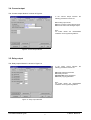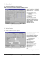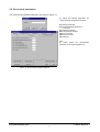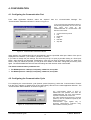
1
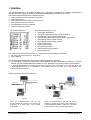
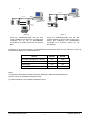
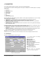
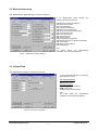
CONFIGURATOR Program for
SM-300 Remote Control Units
USER’S MANUAL
1st edition
Manufacturer:
Nivelco Process Control Co. Ltd.
H-1043 Budapest, Dugonics u. 11.
Phone: (36-1) 369-7575 Fax: (36-1) 369-8585E-mail: [email protected] http://www.nivelco.hu
TABLE OF CONTENTS
1. GENERAL ........................................................................................................................................... 3
2. INSTALLATION AND GETTING STARTED ...................................................................................... 5
2. MAIN APPLICATION WINDOW ......................................................................................................... 6
3. PARAMETERS.................................................................................................................................... 7
3.1. INITIALIZATION ................................................................................................................................. 7
3.2. MEASUREMENT SETUP ..................................................................................................................... 8
3.3. VOLUME/FLOW ................................................................................................................................ 8
3.4. CURRENT
OUTPUT .......................................................................................................................... 9
3.5. RELAY OUTPUT................................................................................................................................ 9
3.6. INFORMATIONAL ............................................................................................................................ 10
3.7. TEST AND SERVICE....................................................................................................................... 10
3.8. SECRET CODE PARAMETERS .......................................................................................................... 11
4. CONFIGURATION ............................................................................................................................ 12
4.1. CONFIGURING THE COMMUNICATION PORT ..................................................................................... 12
4.2. CONFIGURING THE COMMUNICATION CYCLE ................................................................................... 12
4.3. CONFIGURING THE ADDRESS AND SUBADDRESS (ONLY FOR RS 485 PROTOCOL) ............................. 13
4.4. PASSWORD ................................................................................................................................... 13
5. AUTOMATIC MEASUREMENT COLLECTION .............................................................................. 14
6. DATA LOGGING.............................................................................................................................. 16
7. DEBUGGING..................................................................................................................................... 17
7.1. DEBUGGING COMMUNICATION ........................................................................................................ 17
7.2. ERROR LOG .................................................................................................................................. 17
8. TERMINAL WINDOW (ONLY FOR RS 232 PROTOCOL)............................................................... 18
9. PROJECT MANAGEMENT .............................................................................................................. 19
9.1. CREATING A NEW PROJECT ........................................................................................................... 19
9.2. OPENING AN EXISTING PROJECT .................................................................................................... 19
9.3. SAVING A PROJECT....................................................................................................................... 19
9.4. DELETING A PROJECT .................................................................................................................... 20
9.5. PROJECT PROPERTIES .................................................................................................................. 20
CONFIGURATOR Program
USER’S MANUAL
2
1. GENERAL
The CONFIGURATOR is a program designed for configuration management, automatic measurement
collection and data logging of NIVELCO NIVOSONAR SM300 Series Remote Control Units.
The CONFIGURATOR supports the following actions:
♦ Collect parameters from a Remote Control Unit
♦ Modify parameters
♦ Send new parameters to a Remote Control Unit
♦ Save parameters set to a disk file
♦ Load parameters set from a disk file
♦ Collect measurement values
The CONFIGURATOR
consists of the following files :
With CONFIGURATOR you can:
♦ View/modify parameters
♦ View/modify parameters using Terminal Window
♦ Automatically collect measurement values
♦ Automatically collect and store data logging parameters
♦ View/change communication settings
♦ View/change communication protocol
♦ Create a new project
♦ Open existing project
♦ Delete existing project
♦ View/change project properties
♦ Change password
The CONFIGURATOR is delivered on a 3.5“ floppy disk with the following accessories:
♦ RS 232 C connector with a 2 m long cable
♦ User’s Manual
The CONFIGURATOR supports both RS232 and RS 485 interface protocols.
♦ For individually testing and configuring the NIVOSONAR Two-part Measurement System(s), one after
another, use the CONFIGURATOR (installed on a PC, preferably on a laptop) via the RS 232 interface.
♦ If several NIVOSONAR Two-part Measurement Systems are connected to an RS 485 BUS, the
CONFIGURATOR can be in installed on the Process Control PC itself and it will operate upon
RS 485 interface protocol.
The Figures below show some examples.
2 x 4-20 mA analgue outputs
SenSonar Sensor 1
RS 232 Interface
RS 485
Interface
SenSonar Sensor 1
SenSonar Sensor 2
PROCESS CONTROL
COMPUTER
SenSonar Sensor 3
SLM 308
SMM 300
RS 232 Interface
Figure 1.
Figure 2.
Using the CONFIGURATOR with RS 232
protocol installed on a laptop PC for testing and
configuring of a stand alone wall mounted
NIVOSONAR.
Using the CONFIGURATOR with RS 232 protocol
installed on a laptop PC for testing and configuring of
a NIVOSONAR-SCANNER combination connected
to the Process Control PC via RS 485 interface.
CONFIGURATOR Program
USER’S MANUAL
3
RS 485 BUS
RS 485
Interface
RS 485
Interface
PROCESS CONTROL
COMPUTER
RS 485
Interface
SMM300 /1
PROCESS CONTROL
COMPUTER
SMM300 /1
RS 485
Interface
RS 485
Interface
RS 485 BUS
RS 485
Interface
RS 485
Interface
SMM300/2
SMM300/2
SMM300/99
SenSonar Sensor 1
SMM300/99
SenSonar Sensor 3
RS 232 Interface
SLM 308
Figure 3.
Figure 4.
Using the CONFIGURATOR with RS 232
protocol installed on a laptop PC for testing and
configuring one by one of NIVOSONARs
connected to a Process Control PC via RS 485
BUS.
Using the CONFIGURATOR with RS 485
protocol installed on the Process Control PC for
testing and configuring the NIVOSONARs
connected to a Process Control PC via
RS 485 BUS.
Depending on the protocol selection, CONFIGURATOR automatically adjust its user interface to offer only
the features available for the selected protocol.
Feature
Automatic measurement collection
Edit parameters
1
2
Data logging
Terminal window
3
RS 232
RS 485
Yes
Yes
Yes
Yes
Yes
Yes
Yes
No
Notes:
(1) Automatic measurement collection behaves differently in RS232 and RS485 protocol.
(2) Echo map is not available via RS485 protocol.
(3) Terminal window is not available via RS485 protocol.
CONFIGURATOR Program
USER’S MANUAL
4
3. INSTALLATION AND GETTING STARTED
CONFIGURATOR is a Win32 program running on Windows 95, Windows NT or Windows 98 operating
systems. In order to connect the PC to Remote Control Units, it must have at least one available serial port.
The steps of installation are as follows:
♦
Select from “Settings” the “Control Panel”
♦
In “Control Panel” double click on “Add/Remove Programs”
♦
Double click on “Install” button
♦
Place the floppy disk in the drive and click on the “Next” button.
♦
The Window displays “SETUP.EXE”
♦
Press ENTER
♦
Double click on “Next” button for each step till it finishes the installation, including the creation of
directory and the icon.
For getting started:
♦
Double click on the icon of “Nivelco Configurator”
or
♦
Select the “Programs” from “Start” menu then double click on the “Nivelco Configurator” in the “Program
list”.
CONFIGURATOR Program
USER’S MANUAL
5
3. MAIN APPLICATION WINDOW
The Main Application Window is shown in Figure 5. You can reach all program functionalities by either
selecting a menu option or clicking on a toolbar button. The menu options of Main Application Window are as
follows:
File menu:
♦ New project
♦ Open project
♦ Save project
♦ Delete project
♦ Properties
View menu:
♦ Start/stop measurement
collection
♦ Edit parameters
♦ Data logging
♦ Terminal window
♦ Debug communications
♦ Error log
Commands menu:
♦ STEP
♦ MEAS
♦ INIT
♦ FACTORY
♦ RESET
Options menu:
♦ Change password
♦ Unit address
♦ Communication
setting
♦ Communication
timeout
CONFIGURATOR supports both RS 232 and RS 485 communication protocols. With both protocols,
CONFIGURATOR can automatically and periodically collect measurement values.
With RS 485 you can select one of the Remote Control Units connected to RS 485 BUS by specifying its
address (See Figure 4). You can select a SenSonar sensor on the addressed Remote Control Unit by
specifying its sub-address. For modifying these values select the “Unit Address” from menu “Options” or
double click on the “Address/Sub-address” edit boxes on the “Main Application Window”. See Section 4.3.
“Configuring Address and Sub-address“
The communication cycle (interval, “frequency”) is given in milliseconds. If you want a more frequent refresh,
reduce this value. This value should not be less then 5000 ms (5 seconds) due to the limitation of Remote
Control Units. To change this value, select the “Communication Timeout” from the menu “Options” or double
click on the “Interval (ms)” edit box on the “Main Application Window”. See Section 4.2. “Configuring
Communication Cycle”.
Figure 5. Main Application Window
CONFIGURATOR Program
USER’S MANUAL
6
4. PARAMETERS
From “Main Application Window” select the “View” then the “Edit Parameters”.
The parameter set is split into following groups. Each group is displayed on a different page in a property
sheet window.
♦
♦
♦
♦
♦
♦
♦
♦
Initialization
Measurement Set-up
Volume/Flow
Current Output
Relay Output
Info
Test/Service
Secret Code Parameters
User can select one of the following actions related to all the pages (all parameters) or only for currently
active page (visible parameters).
♦ “Download all”: CONFIGURATOR will collect all parameters from the Remote Control Unit.
♦ “Upload all”: CONFIGURATOR will send all parameters to the Remote Control Unit.
♦ “Download this page”: CONFIGURATOR will collect from the Remote Control Unit only parameters
belonging to the currently active page.
♦ “Upload this page”: CONFIGURATOR will send to the Remote Control Unit only parameters belonging
to the currently active page.
For single parameter actions, click once with a right mouse button on a control box containing the value of
the parameter and a local menu will be displayed with the following options:
♦ “Download P_ parameter”: CONFIGURATOR will collect the value of this parameter from the Remote
Control Unit.
♦ “Upload P_ parameter”: CONFIGURATOR will send the value of the parameter to the Remote Control
Unit. This option is available only if the parameter can be sent to the Remote Control Unit.
♦ “Help for P_ parameter”: CONFIGURATOR will show help info for the parameter.
Note:
Parameters that can be modified and sent to the Remote Control Unit are displayed in dark blue color.
3.1. Initialization
Select the “Initializing Window” shown in Figure 6.
In the “Initializing Window” the following
parameters can be set:
P01: Sensor model
P02: Main operating mode
P03: Display mode
P04: Percentage assignment
P05: 0% value for displaying
P06: 100% value for displaying percentage
P07: Sensor configuration
P09: Relay configuration
P61: Number of sensors connected to the
SLM-308 scanner
P62: Display changing mode
P63: Display changing interval
Note:
For further details see “NIVOSONAR
Installation and Programming Manual”.
Figure 6. Initializing Window
CONFIGURATOR Program
USER’S MANUAL
7
3.2. Measurement setup
The “Measurement Setup Window” is shown in Figure 7.
In the “Measurement Setup Window” the
following parameters can be set.
P13: Maximum measuring distance
P14: Close-end-blocking
P15: Far-end-blocking
P21: Target tracking speed
P22: Echo-loss error indication
P23: Echo-loss indication during filling
P24: Level elevation rate
P25: Level descent rate
P26: Angle of repose
P27: Sound velocity
P29: Synchronizing Input Mode
P30: Distance for Remote Distance Calibration
P31: Linearisation
P34: Manual echo selection
P60: Filtering time
Note:
For
further
details
see
“NIVOSONAR
Installation and Programming Manual”.
Figure 7. Measurement Setup Window
3.3. Volume/Flow
The “Volume/Flow Window” is shown in Figure 8.
In the “Volume/Flow Window” the following
parameters can be set:
For volume metering:
P16: Tank/silo shape
P28: Specific gravity
For flow metering:
P16: Principle of flow metering
P84: Head of flow
P17-20: Flume/weir dimensions
Note:
For further details see “NIVOSONAR
Installation and Programming Manual”.
Figure 8. Volume /Flow Window
CONFIGURATOR Program
USER’S MANUAL
8
3.4. Current output
The “Current Output Window” is shown in Figure 9.
In the “Current Output Window” the
following parameters can be set:
P41: Analog output mode
P42: 0/4 mA value of the analogue output
P43: 20 mA value of the analogue output
Note:
For further details see “NIVOSONAR
Installation and Programming Manual”.
Figure 9. Current Output Window
3.5. Relay output
The “Relay Output Window” is shown in Figure 10.
In the “Relay Output Window”
following parameters can be set:
the
P50: Relay selecting parameter
P51: Relay Function
P52, P53, P54: Relay parameters
P55: Relay copying parameter
Note:
For further details see “NIVOSONAR
Installation and Programming Manual
Figure 10. Relay Output Window
CONFIGURATOR Program
USER’S MANUAL
9
3.6. Informational
The “Informational (Info) Window” is shown in Figure 11.
“Data Logging” function is available for both RS232 and RS485 protocols.
When “Data Logging” is activated, the
following parameters will periodically be
collected and shown on “Informational
(Info) Window”:
P74: Current external or sensor
temperature
P75: Maximum external or sensor
temperature
P76: Minimum external or sensor
temperature
P77: Sensor gain
P78: Current number of echoes
P79: Echo map (Only with RS232
communication protocol)
P80: Position of “measurement window”
P81: Echo amplitude in “measurement
window”
P82: Blocking distance
P83: Signal to noise ratio
P84: The headwater
Figure 11. Informational Window
3.7. Test and Service
The “Test/Service Window” is shown in Figure 11.
In the “Test/Service Window” the following
parameters can be checked:
P70: Overall operating hours of
NIVOSONAR
P71: Time elapsed after last switch-on
P72: Relay’s operating hours set in
parameter P50
P73: Switching cycle number of the relay
set in parameter P50
P85: Analog output test
P86: Relay test
P88: LCD test
P89: Compatibility parameter
P90: Program checksum
P92: Simulation Mode
P93: Cycle time for the simulation
P94: Simulated low level value
P95: Simulated high level value
P96: Hardware code
P98: Software code
P99: Access Lock
Figure 12. Test / Service Window
Note:
For further details see “NIVOSONAR
Installation and Programming Manual”.
CONFIGURATOR Program
USER’S MANUAL
10
3.8. Secret code parameters
The “Secret Code Parameters Windows” are shown in Figure 13.
For setting the following parameters the
correct password should be entered first.
P12: Special parameter
P35: Signal amplitude threshold of
“echo-loss”
P37: Distance OFFSET)
P38: Temperature OFFSET
P44: 0 mA OFFSET
P45: 20 mA OFFSET
P91: Gain test
Note:
For further details see “NIVOSONAR
Installation and Programming Manual”.
Figure 13. Secret Code Parameters Window
CONFIGURATOR Program
USER’S MANUAL
11
4. CONFIGURATION
4.1. Configuring the Communication Port
From “Main Application Window” select the “Options” then the “Communication Settings” The
“Communication Parameters Window” is shown in Figure 14.
In the “Communication Parameters Window”
the following parameters can be set for the
PC’s
serial
port
used
by
the
CONFIGURATOR for communication with
Remote Control Units:
♦
♦
♦
♦
♦
♦
Communications protocol
Port
Baud rate
Parity
Data bits
Stop bits
Figure.14. Communication Parameters Window
When started, the CONFIGURATOR will automatically open the specified serial port. Status of the port is
displayed on the window – port is either “opened” or “closed”.
If you want to change the port settings, first close the port (if it is open) by double clicking on “Close port”
button. After finishing the parameter modifications, open the port again by double clicking on “Open port”
button. If the port cannot be opened, you will get an error status. In this case, change the port and try once
again. The CONFIGURATOR will store the last settings and will use them when next started.
The default communication parameters are:
♦
♦
For RS485 protocol: 1200 bps, Odd parity, 8 data bits, 2 stop bits.
For RS232 protocol: 1200 bps, Odd parity, 8 data bits, 2 stop bits.
4.2. Configuring the Communication Cycle
For configuring the communication cycle (timeout, period, frequency), select the “Communication Timeout”
from the menu “Options” or double click on the “Interval(ms)” edit box on the “Main Application Window”. The
“Communication Period Window” is shown in Figure 14.
The communication period is given in
milliseconds and specifies how often the
CONFIGURATOR will send communication
requests to the Remote Control Unit.
This value should not be less then 5 seconds
(5000 ms). This is a limitation imposed by the
Remote Control Unit.
Communication cycle applies only to
Automatic Measurement Collection using
either RS485 or RS232 protocol.
Figure.15. Communication Period Window
CONFIGURATOR Program
USER’S MANUAL
12
4.3. Configuring the Address and Sub-address (only for RS 485 protocol)
For configuring the Remote Control Unit address/sub-address select the “Unit Address” from menu “Options”
or double click on the “Address/Sub-address” edit boxes on the “Main Application Window”.
The “Address/Sub-address Window” is shown in Figure 16.
The valid address range for Remote Control
Unit is from 1 to 99. If a Remote Control Unit
supports more than one sensor, sub-address
should be specified for each sensor (valid subaddress range is from 0 to 7). If there is only
one sensor, set sub-address to 0.
If you specify an invalid address and/or subaddress, CONFIGURATOR will get an error
code during communication session.
Figure 16. New Address/Sub-address Window
4.4. Password
Secret code parameters will be accessible only,
if the correct password is entered. By default,
there is no password assigned (it is empty).
For setting or changing the password, select
the “Change Password” from menu “Options”.
The “Password Window” is shown in Figure 17.
Figure 17. Password Window
CONFIGURATOR Program
USER’S MANUAL
13
5. AUTOMATIC MEASUREMENT COLLECTION
The “Main Application Window” (see Figure 5.) displays the data of last measurement (if the
CONFIGURATOR is communicating with a Remote Control Unit). This display will automatically be refreshed
if the communication is started. The communication can be started or stopped by clicking on the “Start(Stop)
button”.
Before any command to request for measurement data is sent to the Remote Control Unit, these fields are
cleared and a “status field” on the bottom left side of the Window is set to green (indicating that
CONFIGURATOR is waiting for answer from the Remote Control Unit). When the answer is received, colour
will change from green to grey and measurement data are shown in appropriate fields.
If there is an error in communication or there is no answer from the Remote Control Unit, CONFIGURATOR
will repeat request 3 times. Then the “status field” turned to grey shows the total number of requests and
errors.
Green buttons on the top of the “Main Application Window” corresponding to the functions in menu
“Commands” and to the command push buttons on the front panel of Remote Control Unit are used to send
a command to the Remote Control Unit.
S:
M:
P:
I:
F:
R:
STEP
MEAS
PROG
INIT
FACTORY
RESET
The display of measurement data depends on the selected communication protocol.
RS 485 PROTOCOL
When
this
protocol
is
selected,
CONFIGURATOR will display the following
information after collecting measurement
values from the Remote Control Unit.
Figure 18.
Measurement data display for RS 485 protocol
Type:
This field displays the current settings of the Remote Control Unit (display mode indicator) and can be one of
the following:
♦
DIST
♦
TOT2
♦
LEV
♦
RATE
♦
VOL
♦
DIFF. LEV.
♦
FLOW
♦
TIME
♦
TOT1
CONFIGURATOR Program
USER’S MANUAL
14
Unit:
This field displays the current settings of the Remote Control Unit (engineering unit of the currently displayed
value) and can be one of the following:
♦
M
♦
o
♦
l/s
C
♦
m/s
♦
3
m /s
♦
%
♦
l/h
♦
m/h
♦
3
m /h
♦
s
♦
l/day
♦
h
♦
3
♦
t
♦
m /day
3
m
Value:
This field displays the current measurement of the Remote Control Unit (depending on the Type value).
Display:
This field displays the current value on the display of the Remote Control Unit.
RS 232 PROTOCOL
When this protocol is selected, CONFIGURATOR displays the following information after collecting
measurement values from the Remote Control Unit. (See Figure 5.)
♦
Distance
♦
TOT1
♦
Level
♦
TOT2
♦
Flow
♦
m/h
♦
Temperature
♦
Iout
♦
Volume
♦
Rel
♦
Rate
Note:
Depending on the parameter P03 all fields or only a few of them are displayed
CONFIGURATOR Program
USER’S MANUAL
15
6. DATA LOGGING
From Main Application Window select the View then the Data Logging. The Data Logging Window is shown
in Figure 19.
Data logging is available for both RS232 and
RS485 protocols. When data logging is activated,
CONFIGURATOR will periodically collect the
following parameters and save them to a
specified comma separated (.csv) file for later
analysis by Microsoft Excel:
P74: Present temperature
P77: Sensor gain
P78: Current number of echoes
P79: Echo map. (Only for RS232 communication
protocol )
P80: Window position
P81: Amplitude of the echo
P82: Blocking distance
P83: Signal to noise ratio
Figure 19. Data Logging Window
The following options can be specified for a Data Logging:
♦
♦
Period in minutes defines how often will the CONFIGURATOR collect all the above parameters and save
them to a file.
Filename defines full path where the file with data logging values will be stored. File extension is fixed to
".csv". If filename is not defined, CONFIGURATOR will still collect all parameter values but will not store
them to a disk file.
Data logging is started by clicking on the “Start button”. Once it is started, this window cannot be closed until
data logging is stopped by clicking on the “Stop button”.
When storing data to a specified file, CONFIGURATOR automatically prepares a “timestamp” to each record.
The structure of the logged record is the following:
Day
Month
Year
Hour
Minute
Second
P74
P77
P78
P79
……
P79
P80
P81
P82
P83
1…31
1..12
4 digit format (for example, 1999)
0…23
0…59
0…59
As returned from the Remote Control Unit without any formatting. If necessary, user may
write a simple macro in MS Excel to format the values in any way wanted.
-“-“Echo 1
……….
Echo 10
-“-“-“-“-
Delimiter between each field depends on a local Microsoft Windows configuration (Control Panel
International Settings).
CONFIGURATOR Program
USER’S MANUAL
16
7. DEBUGGING
7.1. Debugging communication
From “Main Application Window”select the “View” then the “Debug Communication”. The Debug
Communication Window is shown in Figure 20.
This window shows the communication in either
string or hexadecimal format. All commands
sent to and all answers received from the
Remote Control Unit in this window. It is used
for debugging purposes.
Figure 20. Debug Communication Window
♦
If RS232 protocol is used, string format
should be selected since the
communication with the Remote Control
Unit is performed using ASCII strings.
♦
If RS485 protocol is used, hexadecimal
format should be selected since the
interaction with the Remote Control Unit is
performed using binary messages.
7.2. Error log
From “Main Application Window” select the “View” then the “Error Log”. The “Error Log Window” is shown in
Figure 21.
This Error Log Window shows a list of errors
that occurred since the last time the Error Log is
cleared. The Error Log is automatically cleared
when this Window is closed and the bottom left
button “Clear error log on close” is selected.
Any time an error occurs, the CONFIGURATOR
will automatically display the Error Log Window.
It can be closed without clearing the Error Log,
which is useful for future reference.
Figure 21. Error Log Window
When a new error occurs, it is added to the list
(with a “timestamp” indicating when the error
actually
happened)
and
automatically
displayed.
CONFIGURATOR Program
USER’S MANUAL
17
8. TERMINAL WINDOW (ONLY FOR RS 232 PROTOCOL)
From Main Application Window select the View then the Terminal Window. The Terminal Window is shown in
Figure 22.
This window is available only if RS232
communication protocol is selected. Using
this window, user can manually send any
commands to the Remote Control Unit and
will also see all answers received from it.
CONFIGURATOR does not perform any
formatting on sent and/or received strings.
Clicking on “Clear all” button will clear the
window.
Figure 22. Terminal Window
CONFIGURATOR Program
USER’S MANUAL
18
9. PROJECT MANAGEMENT
9.1. Creating a New Project
From Main Application Window select the File then the New Project. The New Project Window is shown in
Figure 23.
Specify a name for the new project. New
project is a file, which contains all parameters
loaded from the Remote Control Unit and
saved to the project.
Optionally You can enter a “project
description” which is visible when opening or
deleting a project or viewing project
properties.
If RS485 protocol is used, the project will
contain parameters for one or more Remote
Control Units (identified with Address) and
one or more sensors (identified with
Subaddress).
Figure 23. New Project Window
9.2. Opening an Existing Project
From Main Application Window select the File then the Open Project. The Open Project Window is shown in
Figure 24.
Select the project to open. Once the project is
opened, CONFIGURATOR will load it and
display the parameters for the currently
specified remote Control Unit (identified with
its address) and its sensor (identified with its
sub-address) -- only for RS485 protocol.
When selecting a project, project description
(if it is defined) is also displayed.
Projects are automatically saved to a directory
where
the
programs
executable
by
CONFIGURATOR are located. Only projects
stored in this directory can be selected and
opened.
Figure 24. Open Project Window
9.3. Saving a Project
From Main Application Window select the File then the Save Project.
When saving a project, the CONFIGURATOR opens a project file and saves the following information:
♦
♦
Project description.
Parameter set (in case RS485 protocol is used, parameters set is saved for currently defined
address/sub-address).
CONFIGURATOR Program
USER’S MANUAL
19
9.4. Deleting a Project
From Main Application Window select the File then the Delete Project. The Delete Project Window is shown
in Figure 25.
Using this Window you can delete project files
that are no longer needed.
CONFIGURATOR will display a confirmation
dialog box before actually deleting a project.
Once the project is deleted, you cannot access
it any more so be careful when using this
option.
It is not possible to delete a project that is
currently opened in the CONFIGURATOR.
Figure 25. Delete Project Window
9.5. Project Properties
From Main Application Window select the File then the Project Properties. The Project Properties Window is
shown in Figure 26.
This menu option displays a window containing
properties of the current project. It contains:
♦
♦
Project name
Project description
Project description for a current project can be
modified. If you created a project without any
description, this is a place where you can
define/modify it. New project description will be
saved to the project file when you save the
project.
Since the CONFIGURATOR uses a custom
DLL for serial communication, this window also
displays the version information of this DLL.
Figure 26. Project Properties Window
sas1010a0600h_01
NIVELCO Process Control Co. Ltd.
July 14, 1999
CONFIGURATOR Program
USER’S MANUAL
20