1
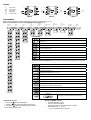
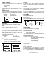
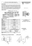
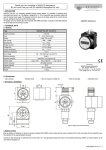
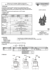
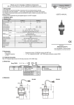
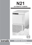
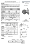
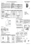
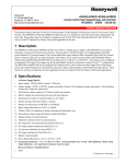
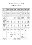
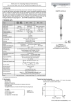
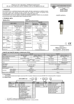
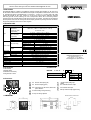
you for choosing a NIVELCO instrument.
We are sure that you will be satisfied throughout its use.
PMG-411, PMG-412, PMG-413
UNIVERSAL CONTROLLER
1. APPLICATION
The UNICONT PMG-411, PMG-412 and PMG-413 universal analogue PID-controllers can be used with a
Pt-100 resistance thermometer and with different thermocouples for temperature measurement, control as well
as processing the signals of transmitters with 4…20 mA and 1…5 V DC or 0…10 V DC output. The output
signal of the controller can be a relay, continous 4…20 mA process current signal or SSR-driver. Additional
alarm relay provides for limit monitoring. The unit is microprocessor based, has an auto-tuning software,
automatic and its PID controller able to find the optimum of the P-I-D constants. The setting can be performed
by the keyboard on the front side. The large bi-coloured display provides easy reading even from far distance.
The process parameters are red, the set values are green.
USER’S MANUAL
2. TECHNICAL DATA
Type
PMG-411-; -412; -413
Resistance
thermometer
(3 cable, aut. cable
compensation)
DIN Pt 100 (–199.9 °C...+199.9 °C or 0 °C...+500 °C)
R cable: max. 5 ohm
Thermocouple
(aut. cold junction
compensator)
Input
Voltage
Current
PID (auto-tuning)
Control output
Output
Alarm output
Setting and display accuracy
PV (process variable)
Display
SV (set value)
Power supply
Protection
Electronic protection
Ambient temperature
Ambient humidity
Dimensions
Weight
K (-100 °C…+1100 °C); J (0 °C…+800 °C)
R (0 °C…+1700 °C); E (0 °C…+800 °C)
T (-200 °C…+400 °C); S (0°C…+1700 °C)
N (0 °C…+1300 °C); W (0 °C…+2300 °C)
1…5 V DC; 0…10 V DC
4…20 mA DC / 250 ohm
Proportional range (P)
0…100%
Integral time (I)
0…3600 s
Derivative time (D)
0…3600 s
Cycle time (C)
1…120 s
Relay
SPDT; 250 V AC, 3 A, AC1
SSR driver
12 V DC ±3 V, max. 30 mA
Current
4…20 mA DC (max. load 600 ohm)
SPST programmable relay, 250 V AC, 1 A, AC1
±0,3 % ±1 digit for the whole input scale or ±3 °C
4 digit, 7 segment 11 mm high red LED
4 digit, 7 segment 7 mm high green LED
90…264 V AC 50/60 Hz, max. 5 VA
Front side: IP 65, Back side: IP 20
Class II Reinforced Isolation
Operational: -10…+50 °C, Storing: -20…+60 °C
35 … 85% RH
48 x 48 x 107 mm (panel cut out: 45.5+0,5 x 45.5+0,5 mm)
0.15 kg
2.1. ACCESSORIES
Manufacturer:
NIVELCO Process Electronics Co. Ltd.
1043 Budapest, Dugonics u. 11.
Phone: 369-7575 ♦ Fax: 369-8585
e-mail: [email protected] http://www.nivelco.com
2.2. ORDER CODE
1 User’s Manual
1 Warranty Sheet
1 Declaration of Conformity
1 Fixing bracket, 2 screws
UNICONT
P M G -
Input
1 Universal input
4
- 1
Code
1
Output
2 relays
SSR driver
4…20 mA
2.3 FRONT PANEL
1
2
3
4
9
7
8
5
3. DIMENSIONS
6
1
PV: Process value display (red)
6
: Display setting keys
2
SV: Set value display (green)
7
EV1: Indicates the alarm output
3
SV2: If this LED is ON, the second, internal set
point is effective.
8
OUT: Indicates the output
9
P/E key: Enters/ escapes programming
4
AT LED: Flashing during auto tuning
5
AT key: auto tuning operation
Minimal distances on the front side
min 55
min 62
Fixing bracket
Code
1
2
3
4. WIRING
US
OUT
IN1
AL1
IN2
:
:
:
:
:
Power Supply
Control Output
Sensor Input
Alarm Output
Processor Input
AL1
+
Pt 100
TC
IN1
10
9
8
7
5
4
12
6
OUT
1
IN1
PMG-411
Program menu can be entered by long and simultaneous pressing of the P/E and
If no key is pressed within 20 s, factory setting (DEFAULT) will be returned.
Alarm
mode
P/E
PID
control
mode
Alarm
latch
P/E
P/E
2
6
10
AL1
SSR
OUT
9
+
Pt 100
8
TC
1
7
4
12
3
11
2
US
+
4...20 mA
OUT
1
PMG-413
keys (t > 3 s)
Cooling or
heating
mode
P/E
5
6
IN1
PMG-412
5. PROGRAMMING
Selecting
sensor
+
3
11
7
US
4
12
8
TC
2
5
9
+
Pt 100
3
11
10
AL1
US
Upper
measurement
limit
Measurement
unit
P/E
P/E
Lower
measurement
limit
P/E
Programming
access lock
P/E
Selecting
sensor
P/E
PROGRAM MENU
Input
Alarm mode
Alarm latch
PID control algorythm
Cooling or heating control
Engineering unit of the temperature measurement unit
Upper measurement limit
Lower measurement limit
Programming access lock
SETTING THE CONTROL PARAMETERS Control parameters can be entered by pressing key P/E longer than
3s
Setting second (internal) set point. Effective with the short circuit of input IN2
Setting operation value of the alarm relay (if operation selected in EV-1 menu)
Setting delay of the loop break indication relay output (0 … 999 s)
(if operation selected in EV-1)
Setting proportional band from 0 % to 100 %
Setting integral time from 0 to 3600 s
Setting derivative time from 0 to 3600 s
Setting cycle time of the control relay from 1 to 120 s
Setting switching difference from 0 to 100°C for ON/OFF control
Modifying the measured value between -49 and +50 °C.
Also applicable with calibration (OFFSET function)
Setting proportional control range from 0 to 100 % (for control only)
Setting rising gradient for RAMP mode if heating (setable range of time to reach the SV: 1 to 99 min)
Setting rising gradient for RAMP mode if cooling (setable range of time to reach the SV: 1 to 99 min)
Access lock
If the access lock is active no parameter can be entered
ON
CHANGING THE SET POINT
• Pressing key set value will be flashing
the required parameter value can be set
• Using key
• Pressing key
again the next parametern will be reached
Confirm settings with the key P/E.
OFF
SETTING THE ON/OFF CONTROL
•
•
•
Set the PID parameters to zero
The „HIS” code will be displayed.
The switching difference can be set in this menu if needed.
Measurement range : 0…100 °C or
0…10.0 °C, depending on the decimal point
SELECT INPUT WITH MEAUREMENT RANGE
DISPLAY
ALARM RELAY DISABLING
INPUT
RANGE
REMARKS
YCA.H
K thermocouple
-100…+1300 °C
YCA.L
K thermocouple
-100…+999 °C
jic.h
J thermocouple
0…+800 °C
jic.l
J thermocouple
0.0…+800.0 °C
R thermocouple
0…+1700 °C
E thermocouple
0…+800 °C
E thermocouple
0.0…+800.0 °C
T thermocouple
-800…+400 °C
T thermocouple
-199.9…+400.0°C
S thermocouple
0…+1700 °C
N thermocouple
0…+1300 °C
W thermocouple
0…+2300 °C
J: Pt 100
0…+500 °C
J: Pt 100
-199.9…+199.9°C
DIN Pt 100
0…+500 °C
DIN Pt 100
-199.9…+199.9°C
0 … 10 V DC
-199.9 … +9999
1 … 5 V DC
-199.9 … +9999
4 … 20 mA
-199.9 … +9999
OPERATION
DESCRIPTION
Standard
No latch
Remains latched after triggering.
Realese by selecting AL-A.
No triggering at first reaching of PV
SV. The output does not switch on if
the PV first reaches the set point (SV).
It triggers only if PV differs from the
SV and reaches the alarm value.
Simultaneous use of latching and
standby order.
Latch
Reduced
Standby Latch
Decimal point
Latch and Standby
Decimal point
SETTING THE ANALOGUE INPUT
Decimal point
Pushing both fasteners on the back side, the instrument can be pulled out of the
box. There are two jumpers (S/W1 and S/W2) inside the instrument. The jumpers
can be carefully pushed off and pulled back according to the figure below.
A.) Resistance thermometer and thermocouple input
B.) Voltage input (1 ... 5 V DC, 0 ... 10 V DC)
Decimal point
Decimal point
Jumper setting
and scaling are
needed
ALARM EVENTS
Only the alarm event can be indicated on the display, which has been selected in
menu Alarm Events.
C.) Current input (4 ... 20 mA)
SV-2 OPERATION (INTERNAL SET POINT)
The SV can be seen on the lower green display and set by the keys on the front
panel.
There is a possibility to set a second internal SV in the SV-2 menu, which is
effective with the short circuit of the input points IN2.
—
Current loop break
—
Sensor break
MEASURED VALUE OFFSET (PARAMETER In-b)
—
Alarm relay failure
Displayed value can be shifted with any value in the parameter In-b menu (Offset
Function). This can be applied for instance for cable compensation with
temperature measurement of two wire Pt 100.
AL-1
SV
PV exceeding the relative
upper limit value.
PV>SV+ AL1
SV
PV exceeding the relative
lower limit value.
PV<SV- AL1
h
AL-1
h
AL-1
AL-1
h
h
PV is outside the range of
the SV
h
PV is within the range of
the SV
SV
AL-1
AL-1
h
SV
h
SV
AL-1
h
AL-1
MODE
SV
Remark: „h” = 2 °C switching difference is fixed.
PV exceeding the
absolute upper limit value.
PV>AL1
PV exceeding the
absolute lower limit value
PV<AL1
SCALING
Measurement range will automatically be determined with the use of Pt 100 or
thermocouple. For analogue inputs (4…20 mA, 0…10 V DC, 1…5 V DC) the low
and the high values have to be entered in menu L-SC (low value) or
H-SC (high value).
SETTING RISING TEMPERATURE GRADIENT (RAMP)
The required delay can be set in the rAPU menu for heating and in rAPd for
cooling is needed. After reaching the new SV, will be kept by the controller.
6. CONTROL ALGORYTHM
There are three different control algorythms, which can be set by the UNICONT
PMG-411, -412 unit.
•
ON / OFF control
•
Proportional (P) control
•
PID control
The best accuracy can be achieved by PID control. The PMG-413 unit with
analogue output can only be used as PID controller.
It is essential to define the control characteristic: whether heating or cooling is
needed.
COOLING/HEATING CONTROL
The unit is able to control the cooling/heating process and it can also be used for
level control. The filling control corresponds with the heating algorithm and the
emptying control with the cooling algorithm.
The algorithm can be selected in menu o-Ft.
Select HEAT:
heating or filling control
•
Select CooL:
cooling or emptying control
Y
PV
PV
Y
PID CONTROL
The PID control is the most commonly used control mode. Similar to the
proportional control PID control will be accomplished by changing the relay’s
energized and de-energized states within its cycle time. Since determination of
the PID parameters by the manual trial and error method the use of the AT mode
is suggested.
AT MODE
Sensing charasteristic features of the control process, the unit determines
automatically the PID parameters and the cycle time.
AT mode will be started by pressing key AT at least 3 s.
During the auto tuning the AT-LED will be blinking and it will turn off if completed.
Auto tuning can be interrupted by pressing key AT for longer than 3 sec. Auto
tuning procedure is suggested to repeat from time to time since thermal features
may be changed.
PID RAMPING MODES
There are two different ramping modes
With the first one, the PV reaches the SV with high speed. In this case a minor
override will occur (Fig. 1.), by the second one the PV reaches the SV slower
but without override (Fig. 2.)
Selecting and setting can be performed in the Pidt menu. PidF means the fast
and PidS the slow setting.
t
t
Cooling/emptying
SV
Heating/filling
PV = process variable
S
SV
PV
PV
Y = control signal
tx: Settle time
S: Overshot
SV: Settled value
PV: Controlled value
ON / OFF CONTROL
Setting the PID parameters to zero the unit can be operating as an ON/OFF
controller.
In this case the controller offers a setable symmetrical switching difference in the
menu HIS.
The heating or cooling algorythm should be set (see menu o-Ft)
PROPORTIONAL (P) CONTROL
In case of proportional control the value of gain (P) is other than zero but the
integral and derivative times are zero. The proportional gain can be set between
1…100%. Control will be accomplished by changing the time of the relay’ss
enerized and de-energized state within the its cycle time. The cycle time of the
relay can be set in the menu T between 1…120 s.
Proportional band: the control range of the cycle. Out of the proportional band
the relay is always energized or deenergized.
The proportional baude:
q = P (%) ⋅ ∆M
where
∆M = measurement range.
The location of the proportional band compared to the SV depends on the
percentage value in the menu rESt. If rESt value = 0%, the whole range is under
the SV.
• If rESt value= 0 %, the whole band is under the SV.
• If rESt value= 50.0 %, the proportional band is symmetrically situated to
the SV
• If rESt value = 100 %, the proportional band is situated over the SV
tx
tx: Settle time
SV: Settled value
PV: Controlled value
tx
PIdS
PIdF
7. FAULT INDICATION
The unit provides for fault indication if it does not work correctly.
The fault indication can be a text on the display or triggering of the Alarm relay.
Fault indications on the display
There are three kinds of fault indiications:
„LLLL”
the measured value is under the lower measurement limit (it is
probable an incorrect input choice)
„HHHH” the measured value is over the upper measurement limit (the input
signal has not been correctly choosen)
„OPEN” the sensor input screw terminal is open (the wire is loose or cut)
Fault indications by the Alarm relay
The Alarm relay can be programmed for two alarm events.
Selecting „LbA” Menu Point: In case of a unit failure the relay will be triggered
with a delay set in Parametr Menu (See SETTING
CONTROL PARAMETERS)
Selecting „SBA” Menu Point: In case of sensor cut the relay will be triggered with
a dely set in Parameter Menu (See SETTING
CONTROL PARAMETERS)
8. STORAGE CONDITIONS
Ambient temperature: -25...+60°C
Air moisture: max. 98 %
SV
q
q
SV
rESt = 0%
R
rESt = 50,0%
R
Relay operation depending on rEST percentage by proportional control
9. WARRANTY
Warranty: two years after the purchase. It can only be validated if presenting both
the warranty sheet and the invoice.
The warrantial repair is carried out at the manufacturer’s seat so the costs of
dismounting and mounting as well as the shipping charge the customer. The
manufacturer accepts the instruments only accurately cleaned or desinfectioned.
We do not guarrantee faults because of irregular use, break and elemental
damage.
pmg4111a0600h_01
April 2002.
Nivelco reserves the right of technical changes.