1
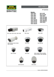
Full HD Multiple Streams IR Bullet
IP Camera
User Manual
Ver1.3 User Name: Admin
Password: 1234
00P3NX053ZXSEA3
Table of Contents
1.
2.
3.
Overview .................................................................................................................................. 2
1.1
Features ........................................................................................................................ 2
1.2
Package Contents ......................................................................................................... 3
1.3
Dimensions.................................................................................................................... 4
1.4
Connectors .................................................................................................................... 5
Camera Cabling....................................................................................................................... 8
2.1
Connect Power.............................................................................................................. 8
2.2
Connect Ethernet Cable ................................................................................................ 8
2.3
Connect Alarm I/O......................................................................................................... 8
Installation ............................................................................................................................... 9
3.1
Ceiling/Wall Mounting.................................................................................................... 9
3.2
Lens Adjustment.......................................................................................................... 10
4.
System Requirements .......................................................................................................... 11
5.
Access Camera ..................................................................................................................... 12
6.
Setup Video Resolution........................................................................................................ 16
7.
Configuration Files Export/ Import...................................................................................... 20
Appendix A: Technical Specifications........................................................................................ 21
Appendix B: Delete the Existing DC Viewer ............................................................................... 24
Appendix C: Setup Internet Security .......................................................................................... 25
Log to NUUO as "Santec" :
SNC-3302 or SNC-4302 or SNC-5312IR or SNC-6032 or SNC-6312IRH
1
1.
Overview
Supported with both H.264 and MJPEG standard, the product series not only
features in superior Full HD resolution for real-time streaming at 25/30 fps, but
also supplies D1 720p real-time streaming. With more computing power, the IP
Camera could provide more flexibility for users and system managers.
1.1
Features
z
z
z
z
z
z
z
z
z
z
z
z
z
z
z
2
Progressive Scan CMOS Sensor
Dual Streams, Full HD real-time + D1 real-time
H.264 and MJPEG compression
Remote Zoom & Focus (Motorized Lens; Optional)
Motion Detection
Privacy Masks
WDR
Smart Picture Quality/3DNR
Tampering Alarm
Day/Night (ICR)
Micro SD support
IR LED module (Optional)
Weatherproof (IP66 International)
Sunshield (Optional)
ONVIF Support
1.2
Package Contents
Please check the package contains the following items listed below.
IR Bullet IP Camera (Cable included)
Power Terminal Block (x1)
M4 Inner Hex Wrench (x1)
M4 Self Tapping Screws
Plastic Screw Anchors
(×5)
(×5)
CD
Quick Guide
(bundled software and documentation)
3
1.3
Dimensions
The IP Camera’s dimensions are shown below.
4
1.4
Connectors
The diagram below shows the IP Dome Camera’s reset button and various
connectors. Definition for each connector will be given as follows.
All-in-one Cable
Cable
Network
(with PoE)
Power
(3-pin Terminal Block)
Alarm
Audio I/O
Pin No.
1
2
3
1
2
3
4
Pink
Green
Definition
Remarks
RJ-45 connector with LED
AC 24V-1
GND
AC 24V-2
ALM_IN-
ALM_IN+
ALM_OUT-
ALM_OUT+
Line In/ Mic In
Line Out
DC (-)
Reserved
DC (+)
Power connection
Alarm connection
Two-way audio transmission
5
SD Card Slot/ Reset Button
Follow the steps below to reach the SD Card Slot, Reboot Button and Factory
Default Button on IP Camera:
Step 1:
Unscrew the two screws on the Sunshield to remove it.
NOTE: Please note that the
Sunshield is optional.
Step 2:
Unscrew the screw on the Camera
Housing and remove the Front
Housing.
Micro SD Card Slot
6
Reboot Button
Factory Default Button
7
2.
Camera Cabling
Please follow the instructions below to complete IP Camera connection.
2.1
Connect Power
Please refer to Section: Connectors. Alternatively, connect the Ethernet cable to
the camera’s PoE port and plug the other end of the cable into a PoE switch.
NOTE: If using PoE, make sure Power Sourcing Equipment (PSE) is in
use in the network.
2.2
Connect Ethernet Cable
Use of Category 5 Ethernet cable is recommended for network connection; to
have best transmission quality, cable length shall not exceed 100 meters.
Connect one end of the Ethernet cable to the RJ-45 connector of the IP Camera,
and the other end of the cable to the network switch or PC.
NOTE: In some cases, you may need use an Ethernet crossover cable
when connecting the IP Camera directly to the PC.
Check the status of the link indicator and activity indicator LEDs; if the LEDs are
unlit, please check LAN connection.
Green Link Light indicates good network connection.
Orange Activity Light flashes for network activity indication.
2.3
Connect Alarm I/O
The camera equips one alarm input and one relay output for alarm application.
Please refer to the label on the alarm terminal block and connect the alarm
wiring accordingly.
8
3.
Installation
Please read the instructions provided in this chapter thoroughly before installing
the IP Dome Camera.
3.1
Ceiling/Wall Mounting
The IR Bullet IP Camera can be installed directly on a wall or ceiling with the
integrated 2-axis adjustable Bracket Mount. Please note that the wall or ceiling
must have enough strength to support the IP Camera.
Follow the steps below to install the IP Camera:
Step 1:
Unpack the IR Bullet IP Camera package and take out the IP Camera.
Step 2:
Connect the power/Ethernet/alarm/audio wires from ceiling or wall to the
corresponding connectors of the camera’s All-in-one Cable.
Step 3:
Fix the IP Camera’s Bracket on the
ceiling/wall with three supplied self
tapping screws
Step 4:
Use the supplied Inner Hex Wrench
and cross screwdriver to loosen the
hex bolt/screw on the side of the
Bracket Mount and the Camera
Housing to adjust the position of the
IP Camera.
9
3.2
Lens Adjustment
Step 1:
Unscrew the screw on the Camera
Housing and remove the Front
Housing.
Step 2:
Power up the IP Camera. Please refer to Section: Connectors for more
cabling installing details.
Step 3:
Access the Camera Browser-viewer for viewing images. Please refer to
Section: Access Camera for further details.
Step 4:
Adjust the Zoom/ Focus to set the desired zoom/ focal length.
10
4.
System Requirements
To perform the IP Camera via web browser, please ensure your PC is in good
network connection, and meet system requirements as described below.
Items
System Requirement
1. Intel® Pentium® M, 2.16 GHz or Intel® CoreTM2 Duo, 2.0
Personal Computer
GHz
2. 2 GB RAM or more
Operating System
Windows VISTA / Windows XP / Windows 7
Web Browser
Microsoft Internet Explorer 6.0 or later
Firefox
Chrome
Safari
Network Card
10Base-T (10 Mbps) or 100Base-TX (100 Mbps) operation
Viewer
ActiveX control plug-in for Microsoft IE
11
5.
Access Camera
For initial access to the IP Camera, users can search the camera through the
installer program: DeviceSearch.exe, which can be found in “DeviceSearch”
folder in the supplied CD.
Device Search Software Setup
Step 1: Double click on the program Device Search.exe. After its window
appears, click on the <Device Search> button on the top side.
Step 2: The security alert window will pop up. Click on <Unblock> to continue.
Device Search
Step 3: Click on <Device Search> again, and all the finding IP devices will be
listed in the page. The IP Camera’s default
IP
address
is:
192.168.0.250.
Step 4: Double click or right click and select <Browse> to access the camera
directly via web browser.
Step 5: Then the prompt window of request for entering default username and
password will appear for logging in to the IP Camera.
The default login ID and password for the Administrator are:
Login ID
Password
Admin
1234
NOTE: ID and password are case sensitive.
NOTE: It is strongly advised that administrator’s password be
altered for the security concerns. Refer to Full HD Multiple
Streams IP Camera Menu Tree for further details.
12
Additionally, users can change the IP Camera’s network property, either DHCP
or Static IP, directly in the device finding list. Refer to the following section for
changing the IP Camera’s network property.
Example of Changing IP Camera’s Network Property
Users can directly change an IP Camera’s network property, ex. from static IP to
DHCP, in the finding device list. The way to change the IP Camera’s network
property is specified below:
Step 1: In the finding device list, click on the IP Camera that you would like to
change its network property. On the selected item, right click and
select “Network Setup.” Meanwhile, record the IP Camera’s MAC
address, for future identification.
Step 2: The “Network Setup” page will come out. Select “DHCP,” and press
“Apply” button down the page.
Step 3: Click on <OK> on the Note of setting change. Wait for one minute to
re-search the IP Camera.
Step 4: Click on the <Device Search> button to search all the devices. Then
select the IP Camera with the correct MAC address. Double click on
the IP Camera, and the login window will come out.
Step 5: Enter User name and Password to access the IP Camera.
Installing DC Viewer Software Online
For the initial access to the IP Camera, a client program, DC Viewer, will be
automatically installed to your PC when connecting to the IP Camera.
If the Web browser doesn’t allow DC Viewer installation, please check the
Internet security settings or ActiveX controls and plug-ins settings (refer to
Section: Setup Internet Security) to continue the process.
The Information Bar (just below the URL bar) may come out and ask for
permission to install the ActiveX Control for displaying video in browser. Right
click on the Information Bar and select <Install ActiveX Control…> to allow the
installation.
13
The download procedure of DC Viewer software is specified as follows.
Step 1: In the DC Viewer installation window, click on <Next> to start
installation.
Step 2: The status bar will show the installation progress. After the installation
is completed, click on <Finish> to exit the installation process.
Step 3: Click on <Finish> to close the DC Viewer installation page.
Once the DC Viewer is successfully installed, the IP Camera’s Home page will
be able to correctly display as the figure below.
Board/ Vari-focal Lens Model
14
Motorized Lens Model
Image and Focus Adjustment
The image displays on the Home page when successfully accessing to the IP
Camera. Adjust zoom and focus as necessary to produce a clear image.
Note: Please refer to Full HD Multiple Streams IP Camera Menu Tree
for more button function detail.
15
6.
Setup Video Resolution
Users can setup Video Resolution on Video Format page of the user-friendly
browser-based configuration interface.
Video Format can be found under this path: Streaming> Video Format.
16
Video Format
Under Video Resolution section, select a preferred resolution setting. The
available Video Resolution for MJPEG & H.264 format includes:
H.264 + H.264
H.264-1
1920 x 1080 (30fps)
H.264-2
BNC SUPPORT
720 x 480 (30fps)*
√
640 x 480 (30fps)
√
352 x 240 (30fps)
√
1920 x 1080 (15fps)
√
1280 x 1024 (30fps)
√
1280 x 720 (30fps)
√
1024 x 768 (30fps)
√
800 x 600 (30fps)
-
720 x 480 (30fps)
√
640 x 480 (30fps)
√
352 x 240 (30fps)
√
1280 x 1024 (15fps)
√
1280 x 720 (30fps)
-
1024 x 768 (30fps)
-
800 x 600 (30fps)
-
720 x 480 (30fps)
√
640 x 480 (30fps)
√
352 x 240 (30fps)
√
1280 x 720 (30fps)
√
1024 x 768 (30fps)
-
800 x 600 (30fps)
-
720 x 480 (30fps)
√
640 x 480 (30fps)
√
352 x 240 (30fps)
√
1024 x 768 (30fps)
√
800 x 600 (30fps)
-
720 x 480 (30fps)
√
640 x 480 (30fps)
√
352 x 240 (30fps)
√
1920 x 1080 (15fps)
1280 x 1024 (30fps)
1280 x 720 (30fps)
1024 x 768 (30fps)
17
800 x 600 (30fps)
√
720 x 480 (30fps)
√
640 x 480 (30fps)
√
352 x 240 (30fps)
√
720 x 480 (30fps)
√
640 x 480 (30fps)
√
352 x 240 (30fps)
√
640 x 480 (30fps)
√
352 x 240 (30fps)
√
352 x 240 (30fps)
-
800 x 600 (30fps)
720 x 480 (30fps)
640 x 480 (30fps)
352 x 240 (30fps)
H.264 + MJPEG
H.264
1920 x 1080 (30fps)
MJPEG
BNC SUPPORT
720 x 480 (30fps)
√
640 x 480 (30fps)
√
352 x 240 (30fps)
√
1920 x 1080 (15fps)
√
1280 x 1024 (30fps)
√
1280 x 720 (30fps)
√
1024 x 768 (30fps)
√
800 x 600 (30fps)
-
720 x 480 (30fps)
√
640 x 480 (30fps)
√
352 x 240 (30fps)
√
1280 x 1024 (15fps)
√
1280 x 720 (30fps)
-
1024 x 768 (30fps)
-
800 x 600 (30fps)
-
720 x 480 (30fps)
√
640 x 480 (30fps)
√
352 x 240 (30fps)
√
1280 x 720 (30fps)
√
1024 x 768 (30fps)
-
800 x 600 (30fps)
-
720 x 480 (30fps)
√
640 x 480 (30fps)
√
352 x 240 (30fps)
√
1920 x 1080 (15fps)
1280 x 1024 (30fps)
1280 x 720 (30fps)
18
1024 x 768 (30fps)
1024 x 768 (30fps)
√
800 x 600 (30fps)
-
720 x 480 (30fps)
√
640 x 480 (30fps)
√
352 x 240 (30fps)
√
800 x 600 (30fps)
√
720 x 480 (30fps)
√
640 x 480 (30fps)
√
352 x 240 (30fps)
√
720 x 480 (30fps)
√
640 x 480 (30fps)
√
352 x 240 (30fps)
√
640 x 480 (30fps)
√
352 x 240 (30fps)
√
352 x 240 (30fps)
-
800 x 600 (30fps)
720 x 480 (30fps)
640 x 480 (30fps)
352 x 240 (30fps)
MJPEG Only
MJPEG
BNC SUPPORT
1920 x 1080 (30fps)
√
1280 x 1024 (30fps)
√
1280 x 720 (30fps)
√
1024 x 768 (30fps)
√
800 x 600 (30fps)
√
720 x 480 (30fps)
√
640 x 480 (30fps)
√
352 x 240 (30fps)
H.264 Only
H.264
BNC SUPPORT
1920 x 1080 (30fps)
√
1280 x 1024 (30fps)
√
1280 x 720 (30fps)
√
1024 x 768 (30fps)
√
800 x 600 (30fps)
√
720 x 480 (30fps)
√
640 x 480 (30fps)
√
352 x 240 (30fps)
-
(*) Default
Click on <Save> to confirm the setting.
19
7.
Configuration Files Export/ Import
To export/ import configuration files, users can access the Maintenance page on
the user-friendly browser-based configuration interface.
The Maintenance setting can be found under this path: System> Maintenance.
Users can export configuration files to a specified location and retrieve data by
uploading an existing configuration file to the IP Camera. It is especially
convenient to make multiple cameras having the same configuration.
Export
Users can save the system settings by exporting the configuration file (.bin) to a
specified location for future use. Click on the <Export> button, and the popup
File Download window will come out. Click on <Save> and specify a desired
location for saving the configuration file.
Upload
To copy an existing configuration file to the IP Camera, please first click on
<Browse> to select the configuration file, and then click on the <Upload> button
for uploading.
20
Appendix A: Technical Specifications
Camera
Full HD Multiple Streams IR Bullet IP Camera
Image Sensor
1/2.7” Progressive CMOS
Effective Pixels
1920(H) x 1080(V)
Minimum
Color
0.2 lux
Illumination
B/W
0.02 lux
Shutter Speed
1~ 1/10000 sec.
White Balance
Manual / AWB/ ATW
Lens
Varifocal/
F1.2/ f =3-9 mm
Lens Type
Motorized Lens
Board Lens
F1.5/ f=4 mm
Varifocal/ Motorized Lens
FOV
103.5(W) ~ 34.3(T)
(16:9 resolution)
Board Lens
78 ゚
Operation
Video Compression
H.264/ MJPEG
Simultaneous H.264 1080p (25/30 fps) + MJPEG D1 (25/30 fps)
Video Streaming
Simultaneous H.264 1080p (25/30 fps) + H.264 D1 (25/30 fps)
H.264
Resolution
Full HD 1080p/ SXGA/ HD 720p/ XGA/ SVGA/ D1/ VGA/ CIF
MJPEG
Brightness
Manual
Exposure
Auto / Manual
Sharpness
Manual
Contrast
Manual
White Balance
Auto / Manual
Saturation
Manual
Backlight Compensation
On/Off
Hue
Manual
Digital Zoom
Support
WDR
On/Off
3D Noise Reduction
On/Off
Motion detection
On/Off
Privacy Mask
On/Off
Privacy Mask Type
Color
Image Setting
ICR *
Tampering Alarm
Auto/ On/ Off
On/Off
21
Two-way Audio
Line out, Line in/ mic in
Audio
Compression
Input
G.711/G.726
5V 10kΩ pull up
Alarm
Output
Event Notification
Photo Relay Output 300V DC/AC
HTTP, FTP, SMTP
Multiple Languages
English, French, German, Italian, Simplified Chinese, Russian, Korean
Network
Interface
10/100Mbps Ethernet (RJ-45)
IPv4/ v6, TCP/IP, UDP, RTP, RTSP, HTTP, HTTPS, ICMP,FTP, SMTP,
Protocol
DHCP, PPPoE, UPnP, IGMP, SNMP, QoS, and ONVIF
Password Levels
User and Administrator
Security
HTTPS, IP Filter, IEEE 802.1X
Internet Browser
Internet Explorer (6.0+), Chrome, Firefox, Safari
User Account
20
Mechanical
Working distance
Up to 25m
Built-in IR
Wavelength
850nm
Illuminator*
Number of LEDs
Power
Connectors
Board lens model: 23, Vari-focal/ Motorized lens model: 24
3-pin terminal block
Ethernet
RJ-45
Micro SD
Micro SDHC 32GB support
Audio Out
Female Stereo Phone Jack, ø 3.5mm
Mic In/ Line In
Female Stereo Phone Jack, ø 3.5mm
Alarm In/ Out
4-pin Alarm Wires
Analog Video
1.0 Vp-p / 75 Ω, BNC
LED Indicator
Power, Link, ACT
General
-10°C ~ 50°C (14°F ~ 122°F)
Operating Temperature
w/Heater, powered by DC12V/AC24V: -35°C ~ 50°C (-31° ~ 122° F)
Humidity: 10% to 90%, no condensation
Power Source
DC12V/ AC24V/ PoE
System: 5W
Power Consumption
(Built-in IR Illuminator: +3W, Motorized Lens: +3.6W, Heater: +10W)
Weatherproof Standard
Regulatory
IP66
CE, FCC, RoHS Compliant
∅ 84 x 180 mm (∅ 3.3 x 7.1 inches)
Dimension
22
w/ Sunshild: ∅ 84 x 193 mm (∅ 3.3 x 7.6 inches)
Weight
0.94 kg (2.07 lbs)
(*) Optional
Note: Motorized Lens will be available in Q4 2011.
23
Appendix B: Delete the Existing DC Viewer
For users who have installed the DC Viewer in the PC previously, please first remove the
existing DC Viewer from the PC before accessing to the IP Camera.
Deleting the DC Viewer
In the Windows <Start Menu>, activate <Control Panel>, and then double click on <Add or
Remove Programs>. In the <Currently installed programs> list, select <DCViewer> and
click on the button <Remove> to uninstall the existing DC Viewer.
Deleting Temporary Internet Files
To improve browser performance, it is suggested to clean up the all the files in the
Temporary Internet Files.
The procedure is as follows:
Step 1: Click on the <Tools> tab on the menu bar and select <Internet Options>.
Step 2: Click on the <Delete> button under <Browsing history> section. Then click on the
<Delete Files> button under the <Temporary Internet files> section.
Step 3: A confirmation window will pop up. Click on <Yes> to start deleting the files.
24
Appendix C: Setup Internet Security
If ActiveX control installation is blocked, please either set Internet security level to default or
change ActiveX controls and plug-ins settings.
Internet Security Level: Default
Step 1: Start the Internet Explorer (IE).
Step 2: Click on the <Tools> tab on the menu bar and select <Internet Options>.
Step 3: Click on the <Security> tab, and select <Internet> zone.
Step 4: Down the page, click on the <Default Level> button and click on <OK> to confirm
the setting. Close the browser window, and restart a new one later to access the IP
Camera.
ActiveX Controls and Plug-ins Settings
Step 1: Repeat Steps 1~3 of the previous section above.
Step 2: Down the page, click on the <Custom Level> button to change ActiveX controls
and plug-ins settings. The Security Settings window will pop up.
Step 3: Under <ActiveX controls and plug-ins>, set ALL items (as listed below) to
<Enable> or <Prompt>. Please note that the items vary by IE version.
ActiveX controls and plug-ins settings:
1. Allow previously unused ActiveX controls to run without prompt.
2. Allow Scriptlets.
3. Automatic prompting for ActiveX controls.
4. Binary and script behaviors.
5. Display video and animation on a webpage that does not use external media player.
6. Download signed ActiveX controls.
7. Download unsigned ActiveX controls.
8. Initialize and script ActiveX controls not marked as safe for scripting.
9. Run ActiveX controls and plug-ins.
10. Script ActiveX controls marked safe for scripting.
Step 4: Click on <OK> to accept the settings and close the Security Settings window.
Step 5: Click on <OK> to close the Internet Options screen.
Step 6: Close the browser window, and restart a new one later to access the IP Camera.
25