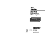
1
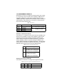
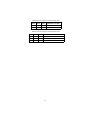
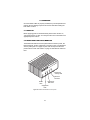
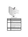
USER
MANUAL
MODEL 2168
CopperLink
Ethernet Extender
Part# 07M2168-A
Doc# 058112UA
Revised 6/11/02
An ISO-9001Certified
Company
SALES OFFICE
(301) 975-1000
TECHNICAL SUPPORT
(301) 975-1007
CONTENTS
1.0
1.1
1.2
1.3
Warranty Information .................................................................
Radio and TV Interference............................................................
CE Notice......................................................................................
Service..........................................................................................
2.0
2.1
2.2
General Information.................................................................... 6
Features........................................................................................ 6
Description.................................................................................... 6
3.0
3.1
3.2
3.3
3.4
Installation................................................................................... 8
Standalone unit installation........................................................... 8
Rack card installation.................................................................... 8
Connecting the Twisted-Pair Line Interface................................ 10
Connecting the 10/100Base-T Ethernet Interface ...................... 11
Connecting the 10/100Base-T Ethernet Port to a Hub ............... 12
Connecting the 10/100Base-T Ethernet Port to a PC (DTE) ...... 12
Connecting Power ...................................................................... 12
3.5
4
4
4
5
4.0
4.1
4.2
Configuration ............................................................................
Configuring the hardware DIP switches......................................
Configuring DIP Switch S1 .........................................................
Switch S1-1: Ethernet Auto Sense .............................................
Switches S1-2 and S1-4: Data Rate...........................................
14
14
16
16
16
5.0
5.1
5.2
Operation................................................................................... 18
Power Up .................................................................................... 18
Front Panel LED Status Monitors ............................................... 18
A
A.1
A.2
A.3
A.4
A.5
A.6
A.7
A.8
A.9
A.10
Specifications ........................................................................... 20
LAN Connection .......................................................................... 20
Transmission Line ....................................................................... 20
CopperLink Line Rate ................................................................. 20
CopperLink Distance .................................................................. 20
CopperLink Surge Suppressor ................................................... 20
LED Status Indicators ................................................................. 20
Power Supply .............................................................................. 20
Temperature Range .................................................................... 20
Humidity ...................................................................................... 20
Dimensions ................................................................................. 20
B
Model 2168 Series Factory
Replacement Parts and Accessories...................................... 21
C
Model 2168 Series Interface Pin Assignment ........................ 22
C.1 10/100Base-T Interface .............................................................. 22
RJ-45 .......................................................................................... 22
2
C.2 CopperLink Interface .................................................................. 22
RJ-45 .......................................................................................... 22
Terminal Block............................................................................ 22
D
Distance Chart, Based on 24 AWG (0.5 mm).......................... 23
3
1.0 WARRANTY INFORMATION
Patton Electronics warrants all Model 2168 components to be free from
defects, and will—at our option—repair or replace the product should it
fail within one year from the first date of the shipment.
This warranty is limited to defects in workmanship or materials, and does
not cover customer damage, abuse or unauthorized modification. If this
product fails or does not performs as warranted, your sole recourse shall
be repair or replacement as described above. Under no condition shall
Patton Electronics be liable for any damages incurred by the use of this
product. These damages include, but are not limited to, the following: lost
profits, lost savings and incidental or consequential damages arising
from the use of or inability to use this product. Patton Electronics specifically disclaims all other warranties, expressed or implied, and the
installation or use of this product shall be deemed an acceptance of
these terms by the user.
Note
Conformity documents of all Patton products can be viewed
online at www.patton.com under the appropriate product page.
1.1 RADIO AND TV INTERFERENCE
The Model 2168 generates and uses radio frequency energy, and if not
installed and used properly-that is, in strict accordance with the manufacturer’s instructions-may cause interference to radio and television reception. The Model 2168 has been tested and found to comply with the limits
for a Class A computing device in accordance with specifications in Subpart B of Part 15 of FCC rules, which are designed to provide reasonable
protection from such interference in a commercial installation. However,
there is no guarantee that interference will not occur in a particular installation. If the Model 2168 does cause interference to radio or television
reception, which can be determined by disconnecting the unit, the user is
encouraged to try to correct the interference by one or more of the following measures: moving the computing equipment away from the receiver,
re-orienting the receiving antenna and/or plugging the receiving equipment into a different AC outlet (such that the computing equipment and
receiver are on different branches).
1.2 CE NOTICE
The CE symbol on your Patton Electronics equipment indicates that it is
in compliance with the Electromagnetic Compatibility (EMC) directive
and the Low Voltage Directive (LVD) of the European Union (EU). A Certificate of Compliance is available by contacting Technical Support.
4
1.3 SERVICE
All warranty and non-warranty repairs must be returned freight prepaid
and insured to Patton Electronics. All returns must have a Return Materials Authorization number on the outside of the shipping container. This
number may be obtained from Patton Electronics Technical Services at:
• Tel: +1 (301) 975-1007
• Email: [email protected]
• URL: http://www.patton.com
Note
Packages received without an RMA number will not be
accepted.
5
2.0 GENERAL INFORMATION
Thank you for your purchase of this Patton Electronics product. This
product has been thoroughly inspected and tested and is warranted for
one year for parts and labor. If any questions or problems arise during
installation or use of this product, contact Patton Electronics Technical
Support at +1 (301) 975-1007.
2.1 FEATURES
• Easy to install standalone Multi-Rate CopperLink Ethernet Extenders—no configuration required
• Auto-sensing full or half-duplex Ethernet
• Auto-sensing 10/100Base-T
• Extends network connections up to 6,652 ft (2.03 km) over 2-wire 24AWG unconditioned lines
• Switch selectable line rates up to 16.67 Mbps
• 7 symmetric or asymmetric settings via DIP switch
• POTS/ISDN splitter on board
• Transparent operation
• LED indicators for Power, Ethernet Link & Activity, CopperLink & Quality of
Line (QOL)
• Surge suppression up to 20 kA (8/20 µs)
• Available in rack-mount or standalone configurations
• Made in the USA
2.2 DESCRIPTION
The Patton Electronics Model 2168/L and 2168/R Multi-Rate CopperLink
Ethernet Extenders provide high-speed LAN connections between
peered Ethernet LANs, remote PC’s, or any other network enabled 10/
100Base-T device.
Operating in pairs, a Model 2168/L (local) located at one end of the LAN
extension and a Model 2168/R (remote) at the other end, these units can
automatically forward LAN broadcasts, multicasts, and frames across a 2wire voice-grade twisted-pair link. The data is passed transparently
(unmodified) through the 2168s. The 2168s automatically add and delete
6
MAC addresses, only passing packets across the CopperLink that are
meant for the remote peered LAN.
Figure 1. Ethernet Extender allows copper instead of fiber for vertical Ethernet spans
Multi-rate Ethernet Extenders are ideal for bridging Ethernet spans inside
buildings that are beyond the 328-foot (100-meter) distance limit of Ethernet.
As shown in Figure 1, connecting workgroups located on different floors in
a building no longer requires expensive switches or the installation of low
capacitance cable.
7
3.0 INSTALLATION
Because the Model 2168 requires no configuration, it can be installed
quickly. If you are installing a standalone unit, refer to section 3.1 “Standalone unit installation”. Otherwise, refer to section 3.2 “Rack card installation”.
Note
If asymmetric transmission or line rates other than 12.5 Mbps
are required, refer to section 4.0, “Configuration” on page 14.
3.1 STANDALONE UNIT INSTALLATION
Do the following:
1. Connect the line interface between the units (refer to section 3.3,
“Connecting the Twisted-Pair Line Interface” on page 10)
Note
See Figure 2 for the standalone unit’s rear panel arrangements.
2. Connect the Ethernet interface (refer to section 3.4, “Connecting the
10/100Base-T Ethernet Interface” on page 11).
3. Connect the power plug (refer to section 3.5, “Connecting Power” on
page 12).
A
de
in
the
US
Ma
k
r
we
Po
Lin
er
pp
Co
er
t
ne
Eth
Ethernet
port
CopperLink
twisted-pair
RJ-45 interface
CopperLink twisted-pair
terminal block
interface
Figure 2. Model 2168 standalone rear panel
3.2 RACK CARD INSTALLATION
The Model 2168 rack card version comprises a front card and a rear
card. Do the following to install the cards into the rack chassis:
1. Slide the rear card into the back of the chassis along the metal rails.
8
2. Secure the rear card using the supplied metal screws.
3. Slide the front card into the chassis until you feel resistance as the
front card engages the rear card. When that happens, gently push
the front card forward until it is fully seated in the card-edge receptacle of the rear card (it should click into place).
4. Secure the front card using the captive fasteners.
Note
The Model 1001R14 chassis supports “hot swapping” of cards,
so it is not necessary to power down the rack when you install or
remove a Model 2168 rack card.
CopperLink
RJ-45 interface
CopperLink
CopperLink
terminal block
Ethernet
Ethernet
Port
Figure 3. Model 2168 rack cards
5. Connect the line interface between the units (refer to section 3.3,
“Connecting the Twisted-Pair Line Interface” on page 10)
Note
See Figure 3 for the rack card’s panel arrangements.
6. Connect the Ethernet interface (refer to section 3.4, “Connecting the
10/100Base-T Ethernet Interface” on page 11).
9
3.3 CONNECTING THE TWISTED-PAIR LINE INTERFACE
The Model 2168 supports communication between two peer Ethernet
LAN sites over a distance of up to 6,652 ft (2.03 km) over 24 AWG
(0.5 mm) twisted-pair wire.
Note
Actual distance and link performance may vary depending on
the environment and type/gauge of wire used.
Follow the steps below to connect the Model 2168 CopperLink Interfaces.
Note
The Model 2168 units work in pairs. One of the units must be a
Model 2168/L (Local), and the other unit must be a Model 2168/
R (Remote). It does not matter which end is the 2168/L and
which is the 2168/R. The link is always initiated by the 2168/R.
As long as the 2168/L is powered on, the 2168/R can establish a
link by being powered on or by having its power reset.
1. To function properly, the two Model 2168s must be connected
together using twisted-pair, unconditioned, dry, metal wire, between
19 (0.9mm) and 26 AWG (0.4mm). Leased circuits that run through
signal equalization equipment are not acceptable.
2. The Model 2168 is equipped with two interface jacks that can be used
on the CopperLink interface, an RJ-45 or a terminal block. These
CopperLink interfaces are a two-wire interface. Observe the signal/pin
relationships on the Model 2168's CopperLink interface jacks.
The RJ-45 connector on the Model 2168's twisted pair interface is polarity insensitive and is wired for a two-wire interface. The signal/pin relationship is shown in Figure 4.
1 (no connection)
2 (no connection)
1
2
3
4
5
6
7
8
3 (no connection)
4 (2-Wire RING)
5 (2-Wire TIP)
6 (no connection)
7 (no connection)
8 (no connection)
Figure 4. Model 2168 (RJ-45) twisted pair line interface.
The terminal block connector on the Model 2168's twisted pair interface
is polarity insensitive and is wired for a two-wire interface. The signal/pin
relationships is shown in Figure 5.
10
A
de
in
the
US
Ma
r
we
Po
K
LIN
V
et
rn
he
Et
RING
TIP
Figure 5. Model 2168 (Terminal Block) twisted pair line interface.
3.4 CONNECTING THE 10/100BASE-T ETHERNET INTERFACE
The shielded RJ-45 port labeled Ethernet is the 10/100Base-T interface.
This port is designed to connect directly to a 10/100Base-T network.
Figure 6 shows the signal/pin relationships on this interface. You may
connect this port to another Ethernet device via a Type 4 or Type 5 cable
that is up to 328 ft long.
1 TX+ (data output from 2168)
2 TX- (data output from 2168)
1
2
3
4
5
6
7
8
3 RX+ (data input to 2168)
4 (no connection)
5 (no connection)
6 RX- (data input to 2168)
7 (no connection)
8 (no connection)
Figure 6. Model 2168 10/100Base-T RJ-45 Connector Pinout.
11
Connecting the 10/100Base-T Ethernet Port to a Hub
The Model 2168 10/100Base-T interface is configured as DTE (Data Terminal Equipment), just like a 10/100Base-T network interface card in a
PC. Therefore, it “expects” to connect to a 10/100Base-T Hub using a
straight-through RJ-45 cable. Figure 7 diagrams the cable wiring for connecting the Model 2168 to a 10/100Base-T hub.
2168 10/100Base-T Port
RJ-45 Pin No.
10/100Base-T Hub
RJ-45 Pin No.
1 (TX+)--------------------------------------------------1 (RX+)
2 (TX-)---------------------------------------------------2 (RX-)
3 (RX+)--------------------------------------------------3 (TX+)
6 (RX-)---------------------------------------------------6 (TX-)
Figure 7. Wiring diagram for connecting the Model 2168 to a 10/100Base-T hub
Connecting the 10/100Base-T Ethernet Port to a PC (DTE)
The Model 2168 10/100Base-T interface is configured as DTE (Data Terminal Equipment). If you wish to connect the 2168 to another DTE
devices such as 10/100Base-T network interface card in a PC (or 2168s
in a back-to-back arrangement), you must construct a 10/100Base-T
crossover cable as shown in Figure 8.
2168 10/100Base-T Port
RJ-45 Pin No.
10/100Base-T DTE
RJ-45 Pin No.
1 (TX+)
1 (TX+)
2 (TX-)
2 (TX-)
3 (RX+)
3 (RX+)
6 (RX-)
6 (RX-)
Figure 8. 10/100Base-T crossover cable
3.5 CONNECTING POWER
An external AC or DC power supply is available separately. This connection is made via the barrel jack on the rear panel of the Model 2168. No
configuration is necessary for the power supply (See Appendix B for
domestic and international power supply and cord options).
DC power (supplied via the power supply jack to the 2168) must meet
the following requirements; DC power supplied must be regulated
+5VDC ±5%, 1.0A minimum. Center pin is +5V. The barrel type plug has
a 2.5/5.5/10mm I.D./O.D./Shaft Length dimensions.
12
The Model 2168 does not have a power switch, so it powers up as soon
as it is plugged in.
13
4.0 CONFIGURATION
The Model 2168 has four DIP switches for configuring the unit for a wide
variety of applications. This section describes switch locations and
explains the different configurations.
4.1 CONFIGURING THE HARDWARE DIP SWITCHES
Using a small flat-tip screwdriver, remove the protective cover located on
the underside of the Model 2168 (see Figure 9).
r
we
Po
Lin
k
QO
L
VL
IN
K
Lin
k
Act
ivity
Eth
ern
et
Co
pp
erL
ink
Eth
ern
et
Ext
en
de
r
Figure 9. Removing protective cover
Figure 10 and Figure 11 on page 15 show the orientation of the DIP
switches in the On and Off positions.
14
S1
1 2 3 4
ON
S1
1
2
3
4
O
Switch toggle
N
S1
Push toggle
down for
OFF position
S1
Push toggle up ON
for ON position
1 2 3 4
Figure 10. DIP switch orientation
S1
ON
Et Co
he pp
rn er
et Lin
Ex k
te
Po n d e r
we
Co
r
pp
er
Lin
k
Lin
k
1 2 3 4
S1
QO
L
et
Switch toggle
4
k
tiv
3
Lin
2
ity
1
S1
Push toggle to left
for ON position
Push toggle
to right for
OFF position
Figure 11. Rack card DIP switch orientation
15
1 2 3 4
Ac
N
rn
O
he
ON
Et
4.2 CONFIGURING DIP SWITCH S1
DIP switch S1 is where you configure the CopperLink line rate, symmetric or asymmetric, Ethernet full auto sense capability (100BaseT full or
half duplex, 10BaseT full or half duplex) or limited auto sense (only
100BaseT half duplex, 10BaseT full or half duplex). Table 1 summarizes
default positions of DIP switches S1-1 through S1-4. Detailed descriptions of each switch follow the table.
Table 1: S1 Summary
Position
Function
Factory Default
S1-1
S1-2
S1-3
S1-4
Ethernet Auto Sense
Line Rate
Line Rate
Line Rate
OFF Full Auto Sense capability
ON
OFF
12.5Mbps Symmetric
OFF
Switch S1-1: Ethernet Auto Sense
Use switch S1-1 to configure the unit for full auto sense capability or limited auto sense capability. Full Auto sense capability consists of standard Ethernet Auto sensing (100BaseT full duplex, 100BaseT half
duplex, 10BaseT full duplex, and 10BaseT half duplex). Limited Auto
sensing capability consists on only auto sensing for 100BaseT half
duplex, 10BaseT full duplex, and 10BaseT half duplex. The limited auto
sensing feature is used when an Ethernet device does not comply with
IEEE 802.3x (back pressure flow control) at 100M full duplex.
Table 2: Ethernet Auto Sense Selection Chart
S1-1
Setting
OFF
Full Auto Sensing
(100 Mbps, Full or Half Duplex)
ON
(10 Mbps, Full or Half Duplex)
Limited Auto Sensing
(100 Mbps Half Duplex)
10 Mbps Full or Half Duplex)
Switches S1-2 and S1-4: Data Rate
Use switches S1-2 and S1-4 to configure the CopperLink line rates.
Table 3: Symmetric CopperLink Line Rates Selection Chart
S1-2
S1-3
S1-4
Symmetric Line Rate
ON
ON
ON
ON
ON
OFF
6.25 Mbps
9.38 Mbps
16
Table 3: Symmetric CopperLink Line Rates Selection Chart
S1-2
S1-3
S1-4
Symmetric Line Rate
ON
ON
OFF
OFF
OFF
ON
12.5 Mbps
16.67 Mbps
Table 4: Asymmetric CopperLink Line Rates Selection Chart
S1-2
S1-3
S1-4
Asymmetric Line Rates DS/US
OFF
OFF
OFF
OFF
ON
ON
ON
ON
OFF
4.17 Mbps/1.56 Mbps
9.38 Mbps/1.56 Mbps
16.67 Mbps/2.34 Mbps
17
5.0 OPERATION
Once the Model 2168s are properly installed, they should operate transparently. No user settings required. This section describes reading the
LED status monitors.
5.1 POWER UP
Before applying power to the Model 2168, please review section 3.5,
“Connecting Power” on page 12 to verify that the unit is connected to the
appropriate power source.
5.2 FRONT PANEL LED STATUS MONITORS
The Model 2168 features five front panel LEDs that monitor power, the
Ethernet signals, and the CopperLink connection. Figure 12 (standalone
version) and Figure 13 on page 19 (rack card version) show the front
panel location of each LED. Table 5 on page 19 describes the LED functions.
et
ern
er
r
de
ten
Ex
in
erL
pp
Co
th
kE
t
ne
Eth
L
er
pp
ity
tiv
Ac
Ink
k
Lin
Co
L
QO
k
Lin
Ethernet
Activity LED
r
we
Po
Ethernet
Link LED
CopperLink
QOL LED
Power
LED
CopperLink
LED
Figure 12. Model 2168 standalone unit front panel
18
ink er
rL nd
pe xte
p
E
r
C on e t
we
r
Po
he
t
E
ink
rL
pe
p
k
Co
Lin
Power
CopperLink Link
CopperLink QOL
OL
Q
E
e
th
Ethernet Link
et
rn
k
n
Li
Ethernet Activity
y
vit
ti
Ac
Figure 13. Model 2168 rack card front panel
Table 5: Front panel LED description
LED
Description
Power
CopperLink Link
Solid GREEN to indicate the unit is powered on.
(Active Green) Solid green (ON) to indicate that the
end-to-end CopperLink between the Model 2168s is
established. The CopperLink LED is OFF when the
link is down.
(Active Yellow) Flashes YELLOW to indicate the processor is correcting an error in the data thus preventing the transmission of corrupted data to the Ethernet
port. The more error corrections, the more often the
LED blinks. If the light remains lit continuously, it
means that the CopperLink line is noisy—although
the data at the Ethernet port remains uncorrupted.
Further impairment of the line however, risks having
the line fail, as indicated by the green CopperLink
Link LED extinguishing.
(Active Green) Solid Green indicates that 10/
100Base-T Ethernet link has been established.
(Active Yellow) Flashes yellow to indicate Ethernet
activity on the Model 2168’s 10/100Base-T Ethernet
port.
CopperLink QOL
Ethernet Link
Ethernet Activity
19
APPENDIX A
SPECIFICATIONS
A.1 LAN CONNECTION
• Shielded RJ-45, 10/100Base-T, IEEE 802.3 Ethernet
• CopperLink Connection: RJ-45 and Terminal Block
A.2 TRANSMISSION LINE
Two-wire unconditioned twisted pair.
A.3 COPPERLINK LINE RATE
16.67 Mbps, symmetric upstream/downstream. Additional symmetric
and asymmetric rates are available via DIP switch settings.
A.4 COPPERLINK DISTANCE
6,000 ft (1.83 km) at 1.56 Mbps upstream/4.17 Mbps downstream
Note
Distances depend on selected line rate.
A.5 COPPERLINK SURGE SUPPRESSOR
Gas tube with maximum current surge: 20 kA (8120 µs).
A.6 LED STATUS INDICATORS
• Power (Green)
• CopperLink: Link (Green) & QOL (Red)
• Ethernet: Link (Green) & Activity (Yellow)
A.7 POWER SUPPLY
External AC and DC options:
• AC: 120 VAC, 220 VAC, and UI (120–240 VAC)
• DC: 12 VDC, 24 VDC and 48 VDC
• Power consumption: 450 mA at 5 VDC
A.8 TEMPERATURE RANGE
0–50°C
A.9 HUMIDITY
Up to 90% non-condensing.
A.10 DIMENSIONS
1.58H x 4.16W x 3.75D in. (10.6H x 4.1W x 8.8D cm)
20
APPENDIX B
MODEL 2168 SERIES FACTORY
REPLACEMENT PARTS AND ACCESSORIES
Patton Model #
Description
Base Models
2168RC/L
2168RC/R
2168/L
2168/R
2168-2PK
07M2168-A
Local Multi-Rate CopperLink Ethernet Extender, Rack Card
Remote Multi-Rate CopperLink Ethernet Extender, Rack Card
Local Multi-Rate CopperLink Ethernet Extender, Standalone
Remote Multi-Rate CopperLink Ethernet Extender, Standalone
Multi-Rate CopperLink Ethernet Extender Kit: includes one local (L)
and one remote (R) Model 2168
User Manual
Power Supplies
08055DCUI
08055-120-5-1
12V-PSM
24V-PSM
48V-PSM
100-240VAC (+5V reg. DC/2A) Universal Input Adapter.
120 VAC (+5V reg. DC/1A) Input Adapter
12 VDC Input Adapter
24 VDC Input Adapter
48 VDC Input Adapter
Power Cords*
0805US
0805EUR
0805UK
0805AUS
0805DEN
0805FR
0805IN
0805IS
0805JAP
0805SW
American Power Cord
European Power Cord CEE 7
United Kingdom Power Cord
Australian Power Cord
Denmark Power Cord
France/Belgium Power Cord
India Power Cord
Israel Power Cord
Japan Power Cord
Switzerland Power Cord
*Only required with optional UI power supply (08055DCUI)
21
APPENDIX C
MODEL 2168 SERIES INTERFACE PIN ASSIGNMENT
C.1 10/100BASE-T INTERFACE
RJ-45
• Pin 1: TX+
• Pin 2: TX• Pin 3: RX+
• Pin 6: RX• Pins 4, 5, 7, 8: no connection
C.2 COPPERLINK INTERFACE
RJ-45
• Pin 4: RING
• Pin 5: TIP
• Pins 1, 2, 3, 6, 7, 8: no connection
Terminal Block
See Figure 5 on page 11.
22
APPENDIX D
DISTANCE CHART, BASED ON 24 AWG (0.5 MM)
Symm Line Rate (DS/US)
Distance in feet (km)
6.25 Mbps
9.38 Mbps
12.5 Mbps
16.67 Mbps
4,500 (1.37)
4,150 (1.26)
4,000 (1.22)
3,300 (1.00)
Asymm Line Rate (DS/US)
Distance in feet (km)
4.17 Mbps/1.56 Mbps (Mode 0)
9.38 Mbps/1.56 Mbps
16.67 Mbps/2.34 Mbps
6,000 (1.83)
5,500 (1.68)
5,000 (1.52)
23
Copyright © 2001, 2002
Patton Electronics Company
All Rights Reserved.
24