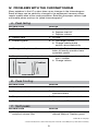
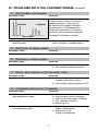
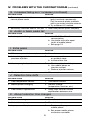
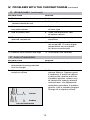
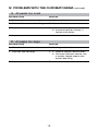
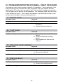
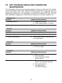
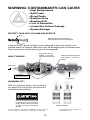
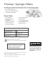
1
HPLC Troubleshooting Guide CALL PHENOMENEX FOR: nHPLC Columns (capillary to preparative) SEC Columns: Aqueous (GFC) and non-Aqueous (GPC) nAmino Acid Analysis nHPLC Specialty Columns for Analysis of: nBasic, acidic and amphoteric drugs nHigh/Low pH separations (pH 1-12) nProteins/Peptides by reversed phase nBiopolymers - Proteins and Nucleic Acids by GFC/SEC nSynthetic polymers nFoods and Beverages n Environmental Samples n Drugs in biological fluids nHPLC Bulk Media nHPLC Accessories such as: nSample and Solvent Filters nSecurityGuard Column Protection nSyringe Filters nSyringes and Vials nColumn Heater / Column Chiller-Heater nHPLC Injection Valves nTubings and Fittings nSolvent Degassers nColumn Selectors nFluid Processors nGC Columns n SPE Tubes and 96-Well plates n nApplication Development and Validation Support Technical Service nOutstanding TABLE OF CONTENTS I. Introduction....................................................................................... 1 II. Abnormal Pressure........................................................................... 2 III. Leaks................................................................................................ 4 IV. Problems with the Chromatogram.................................................... 6 V. Problems with the Injector.............................................................. 14 VI. Problems Detected by Smell, Sight, or Sound............................... 15 VII. Key Problem Areas and Preventive Maintenance........................... 17 SecurityGuard Universal HPLC Guard Cartridge System.............. 19 Phenex Syringe Filters.................................................................... 20 © 2008 Phenomenex, Inc. All rights reserved. No part of this booklet may be copied without prior written permission from Phenomenex, Inc. USA. While every attempt has been made to ensure the accuracy of the information contained in this guide, Phenomenex assumes no responsibility for its use. We welcome any additions or corrections for incorporation into future editions. I. Introduction LOCATING AND CORRECTING THE PROBLEM A systematic approach to identifying the problem is the best approach to troubleshooting your HPLC system. This guide is organized by five major categories of symptoms to help you quickly identify the source of the problem(s) you are encountering: • pressure abnormalities • leaks • problems with the chromatogram • injector problems • other problems detected by the senses of smell, sight, and sound When you have corrected the problem, record the incident in the system recordbook to help with future problems. PREVENTION Many LC problems can be prevented with routine preventive maintenance. For example, replacing pump seals at regular intervals should eliminate pump-seal failure and its associated problems. Section VII lists the most common problem areas for each LC module, and preventive maintenance practices that will reduce their frequency. These suggestions should be modified to fit your particular model of LC, and then made a regular part of your laboratory routine. WHERE TO GET ADDITIONAL HELP • The operator’s and service manuals for the instrument should be consulted. These contain exploded diagrams, troubleshooting procedures for specific models, and part numbers to help you order replacement parts. • Other people in the lab may have had experience solving a problem which is giving you trouble; they can be a helpful resource. • The manufacturer of your instrument can help you. Most LC manufacturers offer free technical support to their customers. • Phenomenex has experienced technical consultants who can assist you with almost any problem. We welcome your phone calls, faxes or emails. • Phenomenex offers seminars, as well as a complete line of reference books on HPLC. • There are a number of reference sources that can give you guidance in problem solving: J.W. Dolan and L.R. Snyder, Troubleshooting LC Systems, Humana Press, NJ (1989). Phenomenex Order No.: AA0-1717 L.R. Snyder and J.J. Kirkland, Introduction to Modern Liquid Chromatography, 2nd ed., Wiley, NY (1979). Phenomenex Order No.: AA0-1700 D.J. Runser, Maintaining and Troubleshooting HPLC Systems - A User’s Guide, Wiley, NY (1981). J.W. Dolan, “Troubleshooting”, LC/GC Magazine. This is a monthly column. 1 II. Abnormal Pressure A change in the operating pressure is a sign that there may be a problem. Choose the category below that best fits the symptoms that you observe, and follow the suggestions to correct the problem. A. No pressure reading, no flow POSSIBLE CAUSE SOLUTION 1. Power off 1. Turn on power 2. Fuse blown 2. Replace fuse 3. Controller setting or failure 3. a. Verify proper settings b. Repair or replace controller 4. Broken piston 4. Replace piston 5. Air trapped in pump head 5. Degas solvents; bleed air from pump, prime pump 6. Insufficient mobile phase 6. a. Replenish reservoir b. Replace inlet frit if blocked 7. Faulty check valve(s) 7. Replace check valve(s) 8. Major leak 8. Tighten or replace fittings B. No pressure reading, flow is normal POSSIBLE CAUSE SOLUTION 1. Faulty meter 1. Replace meter 2. Faulty pressure transducer 2. Replace transducer C. Steady, high pressure POSSIBLE CAUSE SOLUTION 1. Flow rate set too high 1. Adjust setting 2. Blocked column frit 2. a. Backflush column (if permitted) b. Replace frit* c. Replace column 3. Improper mobile phase; 3. a. Use correct mobile phase precipitated buffer b. Wash column 4. Improper column 4. Use proper column 5. Injector blockage 5. Clear blockage or replace injector 6. Column temperature too low 6. Raise temperature 7. Controller malfunction 7. Repair or replace controller 8. Blocked guard column 8. Remove/replace guard column 9. Blocked in-line filter 9. Remove/replace in-line filter * Check manufacturer’s column warranty first. Removal of end-fittings may void column warranty. 2 II. Abnormal Pressure (continued) D. Steady, low pressure POSSIBLE CAUSE SOLUTION 1. Flow set too low 1. Adjust flow rate 2. Leak in system 2. Locate and correct 3. Improper column 3. Use proper column 4. Column temperature too high 4. Lower temperature 5. Controller malfunction 5. Repair or replace controller E. Pressure climbing POSSIBLE CAUSE SOLUTION 1. See section C 1. See section C F. Pressure dropping to zero POSSIBLE CAUSE SOLUTION 1. See sections A and B 1. See sections A and B G. Pressure dropping, but not to zero POSSIBLE CAUSE SOLUTION 1. See section D 1. See section D H. Pressure cycling POSSIBLE CAUSE SOLUTION 1. Air in pump 1. a. Degas solvent b. Bleed air from pump 2. Faulty check valve(s) 2. Replace check valve(s) 3. Pump seal failure 3. Replace pump seal 4. Insufficient degassing 4 a. Degas solvent b. Change degassing methods (use Degassex on-line degasser) 5. Leak in system 5. Locate and correct 6. Using gradient elution 6. Pressure cycling is normal due to viscosity changes 3 III. Leaks Leaks are usually stopped by tightening or replacing a fitting. Be aware, however, that overtightened metal compression fittings can leak and plastic fingertights can wear out. If a fitting leak does not stop when the fitting is tightened a little, take the fitting apart and inspect for damage (e.g. distorted ferrule, or particles on the sealing surface); damaged fittings should be discarded. A. Leaky fittings possible causesolution 1. Loose fitting 1. Tighten 2. Stripped fitting 2. Replace 3. Overtightened* fitting 3. a. Loosen and retighten b. Replace 4. Dirty fitting 4. a. Disassemble and clean b. Replace 5. Mismatched parts 5. Use all parts from same brand B. Leaks at pump possible causesolution 1. Loose check valves 1. a. Tighten check valve (do not overtighten) b. Replace check valve 2. Loose fittings 2. Tighten fittings (do not overtighten) 3. Mixer seal failure 3. a. Replace mixer seal b. Replace mixer 4. Pump seal failure 4. Repair or replace 5. Pressure transducer failure 5. Repair or replace 6. Pulse damper failure 6. Replace pulse damper 7. Proportioning valve failure 7. a. Check diaphragms, replace if leaky b. Check for fitting damage, replace 8. Purge valve 8. a. Tighten valve b. Replace purge valve * Use fingertight end-fittings to avoid sealing problems and the need for wrenches 4 III. Leaks (continued) C. Injector leaks possible causesolution 1. Rotor seal failure 1. Rebuild or replace injector 2. Blocked loop 2. Replace loop 3. Loose injection-port seal 3. Adjust 4. Improper syringe-needle diameter 4. Use correct syringe 5. Waste-line siphoning 5. Keep waste line above surface waste 6. Waste-line blockage 6. Replace waste line D. Column leaks possible causesolution 1. Loose endfitting 1. Tighten endfitting 2. Column packing in ferrule 2. Disassemble, rinse ferrule, reassemble 3. Improper frit thickness 3. Use proper frit (see chart below) E. Detector leaks possible causesolution 1. Cell gasket failure 1. a. Prevent excessive backpressure b. Replace gasket 2. Cracked cell window(s) 2. Replace window(s) 3. Leaky fittings 3. Tighten or replace 4. Blocked waste line 4. Replace waste line 5. Blocked flow cell 5. Rebuild or replace frit Pore Size selection guide Frit Pore Size should be: When Particle Size of material is: 0.5 µm 3 - 4 µm 2 µm 5 - 20 µm 5 IV. Problems with the Chromatogram Many problems in the LC system show up as changes in the chromatogram. Some of these can be solved by changes in the equipment; however, others require modification of the assay procedure. Selecting the proper column type and mobile phase are keys to “good chromatography.” A. Peak tailing possible causesolution 1. Blocked frit 1. a. Reverse fIush column (if allowed) b. Replace inlet frit* c. Replace column 2. Column void 2. Fill void 3. Interfering peak 3. a. Use longer column b. Change mobile phase and/or column/selectivity 4. Wrong mobile phase pH. 4. Adjust pH. For basic compounds, lower pH usually provides more symmetric peaks 5. Sample reacting with active sites. 5. a. Add ion pair reagent or volatile basic modifier b. Change column Normal Problem PEAK TAILING B. Peak fronting possible causesolution 1. Low temperature 1. Increase column temperature 2. Wrong sample solvent 2. Use mobile phase for injection solvent 3. Sample overload 3. Decrease sample concentration 4. Bad column 4. See A.1. and A.2. C. Split peaks possible causesolution 1. Contamination on guard or 1. Remove guard column and analytical column inlet. attempt analysis. Replace guard continued on next page * Check manufacturer’s column warranty first. Removal of end-fittings may void column warranty. 6 IV. Problems with the Chromatogram (continued) C. Split peaks (continued) possible causesolution if necessary. If analytical column is obstructed, reverse and flush. If problem persists, column may Normal Problem be fouled with strongly retained contaminants. Use appropriate restoration procedure. If problem persists, inlet is probably plugged. Change frit or replace column SPLIT PEAKS 2. Sample solvent incompatible with 2. Change solvent. Whenever possible, mobile phase. inject samples in mobile phase D. Distortion of larger peaks POSSIBLE CAUSEsolution 1. Sample overload 1. Reduce sample size E. Distortion of early peaks POSSIBLE CAUSEsolution 1. Wrong injection solvent 1. a. Reduce injection volume b. Use weaker injection solvent F. Tailing, early peaks more than later ones POSSIBLE CAUSEsolution 1. Extra-column effects 1. a. Replumb system (shorter, narrower tubing) b. Use smaller volume detector cell G. Increased tailing as k’ increases POSSIBLE CAUSEsolution 1. Secondaryretention effects, 1. reversed-phase mode a. Add triethylamine (basic samples) b. Add acetate (acidic samples). c. Add salt or buffer (ionic samples) d. Try a different column. e. See page 19 2. Secondaryretention effects, 2. a. Add triethylamine normal-phase mode (basic compounds) b. Add acetic acid (acidic compounds) 7 IV. Problems with the Chromatogram (continued) G. Increased tailing as k’ increases (continued) POSSIBLE CAUSEsolution 2. Secondaryretention effects, 2. c.Add water normal-phase mode (poly-functional compounds). Only for normal-phase methods which use water-miscible solvents. d.Try a different LC method 3. Secondaryretention effects, ion-pair 3. Add triethylamine (basic samples) H. Acidic or basic peaks tail POSSIBLE CAUSEsolution 1. Inadequate buffering 1. a. Use 50-100 mM buffer concentration b. Use buffer with pKa equal to pH of mobile phase c. See page 19 I. Extra peaks POSSIBLE CAUSEsolution 1. Other components in sample 1. Normal 2. Late-eluting peak from 2. a. Increase run time previous injection or gradient slope b. Increase flow rate 3. Vacancy or ghost peaks 3. a. Check purity of mobile phase b. Use mobile phase as injection solvent c. Reduce injection volume 4. Contamination 4. Filter sample J. Retention time drifts POSSIBLE CAUSEsolution 1. Poor temperature control 1. Thermostat column 2. Mobile phase changing 2. Prevent change (evaporation, reaction, etc.) 3. Poor column equilibration 3. Allow more time for column equilibration between runs K. Abrupt retention time changes POSSIBLE CAUSEsolution 1. Flow rate change 1. Reset flowrate 2. Air bubble in pump 2. Bleed air from pump 3. Improper mobile phase 3. a. Replace with proper mobile phase b. Set proper mobile phase mixture on controller 8 IV. Problems with the Chromatogram (continued) L. Baseline drift POSSIBLE CAUSEsolution 1. Column temperature fluctuation. 1. Control column and mobile phase (Even small changes cause cyclic temperature, use heat exchanger baseline rise and fall. Most often before detector affects refractive index and conductivity detectors, or UV Normal Problem detectors at high sensitivity or in BASELINE DRIFT direct photometric mode.) 2. Nonhomogenous mobile phase. 2. (Drift usually to higher absorbance, rather than cyclic pattern from temperature fluctuation.) Use HPLC grade solvents, high purity salts, and additives. Degas mobile phase before use, sparge with helium during use. 3. Contaminant or air buildup in 3. detector cell Flush cell with methanol or other strong solvent. If necessary, clean cell with 1N HNO3 (never with HCI.) 4. Plugged outlet line after detector. 4. Unplug or replace line. Refer (High pressure cracks cell window, to detector manual to replace producing noisy baseline.) window. 5. Mobile phase mixing problem or 5. Correct composition / flow rate. change in flow rate To avoid, routinely monitor composition and flow rate 6. Slow column equililbration, 6. especially when changing mobile phase Flush with intermediate strength solvent, run 10-20 column volumes of new mobile phase before analysis 7. Mobile phase contaminated, 7. Check make-up of mobile phase. deteriorated, or prepared from Use highest grade chemicals and low quality materials HPLC solvents 8. Strongly retained materials in 8. sample (high k’) can elute as very broad peaks and appear to be a rising baseline. (Gradient analyses canaggravate problem.) Use guard column. If necessary, flush column with strong solvent between injections or periodically during analysis. 9. Mobile phase recycled but 9. Reset baseline. Use new mobile detector not adjusted phase when dynamic range of detector is exceeded. 10. Detector (UV) not set at 10. Change wavelength to absorbance maximum but at UV absorbance maximum slope of curve 9 IV. Problems with the Chromatogram (continued) M. Baseline noise (regular) POSSIBLE CAUSEsolution 1. Air in mobile phase, detector cell, 1. Degas mobile phase. Flush or pump system to remove air from detector cell or pump 2. Leak 2. Normal Problem BASELINE NOISE 3. Incomplete mobile phase mixing less viscous solvent See section Ill. Check system for loose fittings. Check pump for leaks, salt build-up, unusual noises. Change pump seals if necessary 3. Mix mobile phase by hand or use 4. Temperature effect (column at high 4. Reduce differential or add heat temperature, detector unheated) exchanger 5. Other electronic equipment on 5. Isolate LC, detector or recorder to same line determine if source of problem is external. Correct as neccessary 6. Pump pulsations 6. Incorporate pulse dampener into system N. Baseline noise (irregular) POSSIBLE CAUSEsolution 1. Leak 1. Normal Problem BASELINE NOISE See section III. Check for loose fittings. Check pump for leaks, salt build-up, unusual noises. Change seals if neccessary. Check for detector cell leak 2. Mobile phase contaminated, 2. Check make-up of mobile phase. deteriorated, or prepared from low quality materials 3. Mobile phase solvents immiscible 3. Select and use only miscible solvents 4. Detector/recorder electronics 4. Isolate detector and recorder electronically. Refer to instruction manual to correct problem 5. Air trapped in system 5. Flush system with strong solvent 6. Air bubbles in detector 6. Purge detector. Install back- pressure device after detector continued on next page 10 IV. Problems with the Chromatogram (continued) N. Baseline noise (irregular) continued POSSIBLE CAUSEsolution 7. Detector cell contaminated (even 7. Clean cell by flushing with small amounts of contaminants 1N HNO3 (never with HCI) can cause noise) 8. Weak detector lamp 8. Replace lamp 9. Column leaking silica or packing material 9. Replace column 10. Mobil phase mixer inadequate 10.Repair or replace the mixer or malfunctioning or mix off-line if isocratic O. Broad peaks POSSIBLE CAUSEsolution 1. Mobile phase composition changed 1. Prepare new mobile phase 2. Mobile phase flow rate too low 2. Adjust flow rate 3. Leaks (especially between column 3. and detector) 4. Detector settings incorrect See section III. Check for loose fittings. Check pump for leaks, salt build-up, and unusual noises. Change seals if necessary 4. Adjust settings 5. Extra-column effects: 5. a. Inject smaller volume (e.g., a. Column overloaded 10 µL vs. 100 µL) or 1:10 and 1:100 dilutions of sample b. Detector response time or cell b. Reduce response time or use volume too large smaller cell c. Tubing between column and c. Use as short a piece of 0.007- detector too long or ID too large 0.010 in. ID tubing as practical d. Recorder response time too high d. Reduce response time Normal Problem BROAD PEAKS 11 IV. Problems with the Chromatogram (continued) O. Broad peaks (continued) POSSIBLE CAUSEsolution 6. Buffer concentration too low 6. Increase concentration 7. Guard column contaminated/worn out 7. Replace guard column 8. Column contaminated / worn out. 8. Replace column with new one Low plate number of same type 9. Void at column inlet 9. Open inlet end and fill void or replace column 10. Peak represents two or more poorly 10.Change column type to improve resolved compounds separation 11. Column temperature too low 11.Increase temperature. Do not exceed 60 °C unless higher temperatures are acceptable to column manufacturer 12. Detector time constant too large 12.Use smaller time constant P. Loss of resolution POSSIBLE CAUSEsolution 1. Mobile phase contaminated / 1. Prepare new mobile phase deteriorated (causing retention time to change) 2. Obstructed guard or 2. analytical column Normal Problem LOSS OF RESOLUTION 12 Remove guard column and attempt analysis. Replace guard if necessary. If analytical column is obstructed, reverse and flush. If problem persists, column may be fouled with strongly retained contaminants. Use appropriate restoration procedure. If problem persists, inlet is probably plugged. Change frit or replace column. IV. Problems with the Chromatogram (continued) Q. All peaks too small POSSIBLE CAUSEsolution 1. Detector attenuation too high 1. Reduce attenuation 2. Detector time constant too large 2. Use smaller time constant 3. Injection size too small 3. a. Increase sample concentration b. Increase injection volume, if column size allows 4. Improper recorder connection 4. Use correct connection R. All peaks too large POSSIBLE CAUSEsolution 1. Detector attenuation too low 1. Use larger attenuation 2. Injection size too large 2. a. Reduce sample concentration b. Decrease injection volume, use a smaller sample loop or use partial loop filling 3. Improper recorder connection 3. Use correct connection 13 V. Problems with the injector These problems are usually detected while you are using the injection valve. Leaky injection valves are discussed in Section III (Leaks). A. Manual injector, hard to turn POSSIBLE CAUSEsolution 1. Damaged rotor seal 1. Rebuild or replace valve 2. Rotor too tight 2. Adjust rotor tension B. Manual injector, hard to load POSSIBLE CAUSEsolution 1. Valve misaligned 1. Adjust alignment. 2. Blocked loop 2. Replace loop 3. Dirty syringe 3. Clean or replace syringe 4. Blocked lines 4. Clear or replace lines C. Autoinjector, won’t turn POSSIBLE CAUSEsolution 1. No air pressure (or power) 1. Supply proper pressure (power) 2. Rotor too tight 2. Adjust 3. Valve misaligned 3. Adjust alignment D. Autoinjector, other problems POSSIBLE CAUSEsolution 1. Blockage 1. Clear or replace blocked portion 2. Jammed mechanism 2. See service manual 3. Faulty controller 3. Repair or replace controller 14 VI. Problems Detected by SMELL, SIGHT OR SOUND You need to use all your senses to identify LC problems. You should get in the habit of taking a few minutes each day to expose all of your senses (except taste!) to the LC so that you can get a “feel” for how the LC performs normally. This will help you to quickly locate problems. For example, often you can smell a leak before you see it. The majority of problems are identified by sight; most of these are included in the preceeding section. A. Solvent smell POSSIBLE CAUSEsolution 1. Leak 1. See section III 2. Spill 2. a. Check for overflowing waste container b. Locate spill and clean up B. “Hot” smell POSSIBLE CAUSEsolution 1. Overheating module 1. a. Check for proper ventilation, adjust b. Check temperature setting, adjust c. Shut module off, see service manual C. Abnormal meter readings POSSIBLE CAUSEsolution 1. Pressure abnormality 1. See section II 2. Column oven problem 2. a. Check settings, adjust b. See service manual 3. Detector lamp failing 3. Replace lamp D. Warning lamps POSSIBLE CAUSEsolution 1. Pressure limit exceeded 1. a. Check for blockage b. Check limit setting, adjust 2. Other warning lamps 2. See service manual 15 VI. Problems Detected by SMELL, SIGHT OR SOUND (continued) E. Warning buzzers POSSIBLE CAUSEsolution 1. Solvent leak / spill 1. Locate and correct 2. Other warning buzzers 2. See service manual F. Squeaks and squeals POSSIBLE CAUSEsolution 1. Bearing failure 1. See service manual 2. Poor lubrication 2. Lubricate as necessary 3. Mechanical wear 3. See service manual 16 VII. key problem areas and preventive maintenance The chart below lists the most common problems that occur with each LC module. In the right-hand column are listed preventive maintenance practices that can reduce the failure rate. The numbers in parentheses are suggested intervals between maintenance. The operator’s and service manuals for your LC may have additional suggestions for preventive maintenance of your model of LC. Reservoir Problempreventive maintenance 1. Blocked inlet frit 1. a. Replace (3-6 mo.) b. Filter mobile phase, 0.5µ filter 2. Gas bubbles 2. Degas mobile phase Pump Problempreventive maintenance 1. Air bubbles 1. Degas mobile phase 2. Pump seal failure 2. Replace (3 mo.) 3. Check valve failure 3. Filter mobile phase, use inlet-line frit. Keep spare Injector Problempreventive maintenance 1. Rotor seal wear 1. a. Don’t overtighten b. Filter samples Column Problempreventive maintenance 1. Blocked frit 1. a. Filter mobile phase b. Filter samples c. Use in-line filter and/or guard column 2. Void at head of column 2. a. Avoid mobile phase pH > 8. (Most silica-based columns) b. Use guard column c. Use precolumn (saturator column) 17 VII.key problem areas and preventive maintenance (continued) Detector Problempreventive maintenance 1. Lamp failure; decreased detector 1. Replace (6 mo.) or keep response; increased detector noise spare lamp 2. Bubbles in cell 2. a. Keep cell clean b. Use restrictor after cell c. Degas mobile phase General Problempreventive maintenance 1. Corrosive/abrasive damage 1. Flush buffer from LC and clean when not in use 18 warning: Contaminants can cause •High Backpressure •Split Peaks •Broad Peaks •Baseline Noise •Baseline Drift •Loss of Resolution •Irreversible Column Damage •System Damage Protect your hplc column and results Additional information can be found at www.phenomenex.com/info/securityguard A universal HPLC guard cartridge system designed to effectively protect your valuable analytical columns and results from the damaging effect of contaminants. Trap contaminants without altering your chromatography. Cutaway view showing Cartridge - can be easily inspected for contaminants How it works*: Universal Fingertight connection to HPLC column - no wrenches required From injector contaminants compounds of interest Holder HPLC column Universal fit*: With the patented design, SecurityGuard can adjust to fit virtually any manufacturer’s female/inverted endfitting. If you are not completely satisfied with the performance of SecurityGuard, simply contact Phenomenex within 45 days and keep SecurityGuard for FREE. *Feature applies to analytical-sized guard system only, and does not apply to SemiPrep or PREP guard cartridges. 19 SecurityGuard is a trademark of Phenomenex, Inc. Phenex Syringe Filters ™ For Sample and Solvent Filtration Prior to Chromatography • Less system down time • Consistent, reproducible results • Increased column lifetime Phenex Offers: »» Low absorption »» Low hold-up volume »» Maximum chemical compatibility »» Certified quality »» Minimum extractables »» Excellent flow rate »» High total throughput »» 100 % integrity tested »» Easy pore identification »» Bi-directional use Membrane Types RC (Regenerated Cellulose) NY (Nylon) PTFE (Polytetrafluoroethylene) CA (Cellulose Acetate) PES (Polyethersulfone) GF (Glass Fiber) Above syringe filters are non-sterile. Housing is made of medical-grade polypropylene (PP). Tip: Try a Sample Pack! The best way to determine if a specific Phenex membrane is suitable for your application. Request yours today by phone or visit www.phenomenex.com/sample Please contact your local Phenomenex technical consultant or distributor for availability or assistance. Larger quantity purchases at significant savings are available. Phenex is a trademark of Phenomenex, Inc. If Phenex Syringe Filters do not perform as well or better than your current syringe filter product of similar membrane, diameter and pore size, return the product with comparative data within 45 days for a FULL REFUND. This publication is distributed free of charge. Additional copies are available from: mail: tel.: fax: email: mail: tel.: fax: email: mail: tel.: fax: email: Australia PO Box 4084 Lane Cove, NSW 2066 Australia Austria Zeppelinstr. 5 63741 Aschaffenburg Germany Belgium Maarssenbroeksedijk 13D 3542 DL Utrecht Netherlands Canada 411 Madrid Ave. Torrance, CA 90501-1430 USA Denmark Gydevang 39-41 3450 Allerød Denmark 02-9428-6444 02-9428-6445 auinfo@ phenomenex.com 01-319-1301 01-319-1300 anfrage@ phenomenex.com +31 (0)30-2418700 +31 (0)30-2383749 beinfo@ phenomenex.com (800) 543-3681 (310) 328-7768 info@ phenomenex.com 4824 8048 4810 6265 dkinfo@ phenomenex.com France Parc des Grillons, Bat.3 60 route de Sartrouville 78232 Le Pecq Cedex France Germany Zeppelinstr. 5 63741 Aschaffenburg Germany Ireland Queens Avenue, Hurdsfield Ind. Est., Macclesfield, Cheshire SK10 2BN, UK Italy Via M. Serenari, 15/D 40013 Castel Maggiore (BO) Italy Luxembourg Maarssenbroeksedijk 13D 3542 DL Utrecht Netherlands 01 30 09 21 10 01 30 09 21 11 franceinfo@ phenomenex.com 06021-58830-0 06021-58830-11 anfrage@ phenomenex.com 01 247 5405 +44 1625-501796 eireinfo@ phenomenex.com 051 6327511 051 6327555 italiainfo@ phenomenex.com +31 (0)30-2418700 +31 (0)30-2383749 nlinfo@ phenomenex.com Netherlands Maarssenbroeksedijk 13D 3542 DL Utrecht Netherlands New Zealand P O Box 31-601 Milford 0741 North Shore City New Zealand Puerto Rico 273 Sierra Morena, Suite #104 San Juan, Puerto Rico 00926 United Kingdom Queens Avenue, Hurdsfield Ind. Est., Macclesfield, Cheshire SK10 2BN, UK USA 411 Madrid Ave. Torrance, CA 90501-1430 USA 030-2418700 030-2383749 nlinfo@ phenomenex.com 09-4780951 09-4780952 nzinfo@ phenomenex.com (800) 541-HPLC (310) 328-7768 info@ phenomenex.com 01625-501367 01625-501796 ukinfo@ phenomenex.com (310) 212-0555 (310) 328-7768 info@ phenomenex.com 6116_L www.phenomenex.com Phenomenex products are available worldwide. For the distributor in your country, contact Phenomenex USA, International Department by telephone, fax or email: [email protected].