1
Commercial Air Conditioning
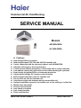
SERVICE MANUAL
Models
AB182ACERA
AC182ACERA
Features
High energy efficiency class-A
New designed panel 700*700 with 600*600 cassette unit
Can be connected with the universal outdoor unit AU182AFERA
Infrared control type or wired control type
Central control and full automation, if connected with a central controller
Low ambient cooling kit (optional) and low ambient heating kit (optional)
New friendly refrigerant R410a, environment protection
Advanced technology, DC inverter control function
Built-in high-head water pump for cassette unit
Pre-set fresh air inlet for cassette unit
Left-side and right-side drainage hole for convertible unit
Optional installation types for convertible unit: on the ceiling or on the floor
Weekly timer (standard)
Group control function
Auto check of troubles
Auto restart function
Room card function
Manual code: SYJS-011-05REV.0
Edition: 2005-10-08
Commercial Air Conditioner
Model: AB182ACERA
AC182ACERA
CONTENTS
Contents………………………………………………………...2
1. Description of products & features………………………..3
2. Specification…………………………………………………5
3. Safety precaution……………………………………………8
4. Net dimension……………………………………………….10
5. Installation instructions………..……………………………11
6. Parts and functions…………………………………………24
7. Infrared controller functions………………………………..25
8. Electrical control functions…………………………………35
9. Electrical data……………………………………………….50
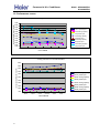
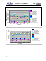
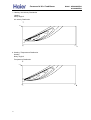
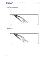
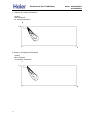
10.Performance curves.......................................................55
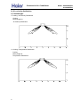
11. Noise level charts..........................................................57
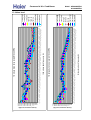
12. Air velocity distribution……………………………………58
2
Commercial Air Conditioner
Model: AB182ACERA
AC182ACERA
1.DESCRIPTION OF PRODUCTS & FEATURES
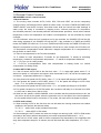
1.1. Products code explanation
A
B 18
2
A C
E R
A
Climate type: T1 (see table 1)
Design number (R stands for design sequence, DC inverter
frequency
type)
Product type: A stands for heat pump type, refrigerant is R22
B stands for heat pump type, refrigerant is R407C
E stands for heat pump type, refrigerant is R410a
Q stands for cool only type, refrigerant is R410A
Design number
Product series: A stands for 1 to 1
Applicable voltage: 2 stands for 220~230V/50Hz,
4 stands for 220V/60Hz,N stand for 380~400VAC/50Hz
Cooling / Heating capacity,18=18000BTU/h
Product type : “B” stands for cassette type, “C” stands for
convertible type, ”D” stands for duct, “S” stands for wall
mounted type, ”Q” stands for chiller system, "E" stands for
ceiling concealed type, “U” stands for outdoor unit
Air Conditioner
1.2 Brief Introduction for T1、T2、T3 working condition
Climate type
Type
of
Conditioner
Air
T1
T2
T3
Cooling Only
18 ℃~43℃
10℃~35℃
21℃~52℃
Heat pump
-7℃~43℃
-7℃~35℃
-7℃~52℃
Electricity Heating
~43℃
~35℃
~52℃
1.3 Operating Range of Air Conditioners
Temp.
Mode
Indoor
Cooling
Outdoor
Indoor
Heating
Outdoor
3
Rated
Maximum
Minimum
DB
℃
27
32
15
WB
℃
19
23
14
DB
℃
35
43
-5
WB
℃
24
26
6
DB
℃
20
27
10
WB
℃
14.5
---
--
DB
℃
7
23
-10
WB
℃
6
18
---
Commercial Air Conditioner
Model: AB182ACERA
AC182ACERA
1.4 Product features
New designed panel 700*700 with the 600*600 cassette unit
New designed swing louver with the non smooth surface, which can hold back the condensant water.
New designed filter lock, which will fix the filter more firmly than before.
Adopts the stepping motor, give the louver a larger swing angel.
New fan with bigger diameter fan blade, sending out larger air flow.
Electric control box is located in the unit, convenient to maintain.
The cassette indoor unit adopts the panel whose dimension is identical to that of ceiling, after installation,
the unit will be accordant with the decoration decor.
Can be connected to the universal outdoor unit AU182AFERA
The universal outdoor unit can match with all types of indoor unit with the same capacity, such as the
cassette type, the convertible type, the duct type, the wall mounted type, and the cabinet type, etc.
Adopt the much friendlier refrigerant R410a
The air conditioner system adopts the greatly friendly refrigerant R410a, which is protective for the
ozone layer and is good to avoid the earth getting warmer. Benefit for the environment.
Adopt the advanced DC inverter technology
The system adopts the advanced DC inverter technology, which can consume less power energy to
realize the equal efficiency, saving money for you.
Smart newly designed infrared remote controller
The unit can be controlled by the newly designed infrared remote controller YR-H71, which can realizes
many functions such as heating, cooling, fan, swing, fresh, health, filter up/down, electric heating, etc.
Furthermore, the remote controller can be compatible with many old controllers, more convenient for
utilizing.
Auto-check function
The unit can display the malfunction codes on the control board by using advanced auto-check
technology, convenient for user find and dwell with the abnormal running.
Auto–restart function (optional)
All indoor units have auto-restart function. When the power supply cut off suddenly, the unit will
automatically recover the previous running mode once the power supply is on.
Room card function
The unit can be used for the hotel or other buildings due to the room card function, which function can
realize the power ON/OFF by putting on or off a card. Easy to manage the building.
Central control function, if connected with a central controller
Low ambient cooling kit (optional) and low ambient heating kit
(optional)
If the unit is equipped with the low ambient cooling/heating kit, it can realize the cooling/heating
operation under the serious condition of ambient temperature is –15degree.
Weekly timing function
4
Commercial Air Conditioner
Model: AB182ACERA
AC182ACERA
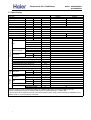
2. Specification
PIPING
Panel
Indoor unit
Item
Model
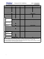
2. SPECIFICATION
Function
Capacity
kW
Sensible heat ratio
Total power input
W
Max. power input
W
EER or COP
W/W
Dehumidifying capacity
10‐³×m³/h
Power cable
Power source
N, V, Hz
Running /Max.Running
A/A
Start Current
A
Circuit breaker
A
Unit model (color)
Type × Number
Speed(H-M-L)
r/min
Fan
Fan motor output power
kW
Air-flow(H-M-L)
m³/h
Type / Diameter
mm
Heat exchanger Total Area
m²
Temp. scope
℃
External (L×W×H) mm×mm×mm
Dimension
Package (L×W×H) mm×mm×mm
Drainage pipe (material , I.D./O.D.)
mm
Control type (Remote /wired)
Fresh air hole dimension
mm
Outlet distribution hole dimension
mm
Electricity Heater
kW
Noise level
(H-M-L)
dB(A)
Weight
(Net / Shipping)
kg / kg
External (L×W×H) mm×mm×mm
Dimension
Package (L×W×H) mm×mm×mm
Weight
(Net / Shipping)
kg / kg
Type / Charge
g
Refrigerant
Recharge quantity
g/m
Liquid
mm
Pipe
Gas
mm
Connecting Method
m
MAX.Drop
Between I.D &O.D
m
MAX.Piping length
AB182ACERA
cooling
heating
5.0(1.8--5.8)
5.2(2.0---6.2)
0.71
/
1660(550---2400)
1730(600---2300)
2650
2650
3.01
3.01
2.1
4.0×3
1, 220--230, 50
7.8(3.0---10.5)/12.0
8.0(3.2---10)/12.0
3A
3A
25A
25A
AB182ACERA(WHITE)
centrifugal*1
760/650/520
0.05
700/----inner grooved pipe/φ7
1.23
2-7
570×570×260
718×680×380
PVC 26/32
Remote
95
/
0
44/---25/27
700×700×60
740×750×115
3.5/4.5
R410A/1850
35
6.35
12.7
flared
15
30
Norminal condition: indoor temperature (cooling): 27 ℃DB/19℃WB, indoor temperature (heating): 20℃DB
Outdoor temperature(cooling): 35℃DB/24℃WB, outdoor temperature(heating): 7℃DB/6℃WB
The noise level will be measured in the third octave band limited values, using a Real Time Analyser calibrated sound
intensity meter. It is a sound pressure noise level.
5
Commercial Air Conditioner
PIPING
Indoor unit
Item
Function
Capacity
Sensible heat ratio
Total power input
Max. power input
EER or COP
Dehumidifying capacity
Power cable
Power source
Running
Start Current
Circuit breaker
Unit model (color)
Model
kW
W
W
W/W
10‐³×m³/h
N, V, Hz
A/A
A
A
Type × Number
Speed(H-M-L)
r/min
Fan
Fan motor output power
kW
Air-flow(H-M-L)
m³/h
Type / Diameter
mm
Heat exchanger
Total Area
m²
Temp. scope
℃
External
(L×W×H) mm×mm×mm
Dimension
Package (L×W×H) mm×mm×mm
Drainage pipe (material , I.D./O.D.)
mm
Control type (Remote /wired)
Fresh air hole dimension
mm
Electricity Heater
kW
Noise level
(H-M-L)
dB(A)
Weight
(Net / Shipping)
kg / kg
Type / Charge
g
Refrigerant
Recharge quantity
g/m
Liquid
mm
Pipe
Gas
mm
Connecting Method
MAX.Drop
m
Between I.D &O.D
MAX.Piping length
m
Model: AB182ACERA
AC182ACERA
AC182ACERA
cooling
heating
5.1(1.8--5.8)
6.0(2.0---7.1)
0.71
1690(550---2650)
1650(600---2650)
2650
2650
3.01
3.63
1.8
4.0×3
1, 220--230, 50
8.0(3.0--12.0)A
7.8(3.2--12.0)A
3
3
25
25
AC182ACERA(WHITE)
CENTRIFUGALX2
1150/1050/850
0.05
750/650/550
inner grooved pipe/φ7
0.45
2-7
1090×655×199
1150×750×300
PVC 18/20
Remote
/
/
50/45/40
30/39
R410A/1850
35
6.35
12.7
flared
15
30
Norminal condition: indoor temperature (cooling): 27℃DB/19℃WB, indoor temperature (heating): 20℃DB
Outdoor temperature(cooling): 35℃DB/24℃WB, outdoor temperature(heating): 7℃DB/6℃WB
The noise level will be measured in the third octave band limited values, using a Real Time Analyser calibrated
sound intensity meter. It is a sound pressure noise level.
6
Commercial Air Conditioner
Model: AB182ACERA
AC182ACERA
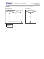
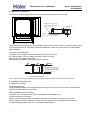
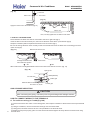
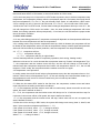
Installation state: the unit should be placed on the flat floor or be mounted in horizontal direction.
Testing method:
mounting-on-ceiling unit:
built-in-ceiling unit:
1m
7
1.4m
1m
Note: ⊙ is the real
time analyser
position
Commercial Air Conditioner
Model: AB182ACERA
AC182ACERA
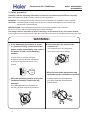
3. Safety precaution
Carefully read the following information in order to operate the airconditioner correctly.
Below are listed three kinds of Safety Cautions and Suggestions.
WARNING! Incorrect operations may result in severe consequences of death or serious injuries.
CAUTION! Incorrect operations may result in injuries or machine damages; in some cases may
cause serious consequences.
INSTRUCTIONS: These information can ensure the correct operation of the machine.
Be sure to conform with the following important Safety Cautions.
The Safety Cautions should be at hand so that they can be checked at any time when needed.
If the conditioner is transferred to the new user, this manual should be as well transferred to the new user.
WARNING!
If any abnormal phenomena is found
(e. g.smell of firing), please cut off the
power supply immediately, and contact
the dealer to find out the handling
method.
Don't dismantle the outlet of the
outdoor unit.
The exposed fan is very dangerous
which may harm human beings.
In such case, to continue using the
conditioner will damage the conditioner,
and may cause electrical shock or fire
hazard.
switch
off
After the unit being used for a long time,
the base should be checked for any
damages.
If the damaged base is not repaired, the
unit may fall down and cause accidents.
8
When the unit needs maintenance and
repairment, please call dealer to handle it.
Incorrect maintenance and repairment
may cause water leak, electrical shock
and fire hazard.
Commercial Air Conditioner
Model: AB182ACERA
AC182ACERA
WARNING!
Installed electrical-leaking circuit
breaker.
Nothing or nobody is permitted to
placed on or stand on outdoor unit.
It easily cause electrical shock without
circuit breaker.
The falling of goods and people may
cause accidents.
Air-conditioner can't be installed in
the environment with inflammable
gases because the inflammable gases
near to air-conditioner may cause fire
hazard.
Please let the dealer be responsible for
installing the conditioner.
Don't operate the air-conditioner with
damp hands.
Incorrect installation may cause water
leak, electrical shock and fire hazard.
Otherwise will be shocked.
Call the dealer to take measures to
prevent the refrigerant from leaking.
If conditioner is installed in a small
room be sure to take every measure in
order to prevent suffocation accident
even in case of refrigerant leakage.
When conditioner is removed or
reinstalled, dealer should be responsible
Only use correctly-typed fuse.
May not use wire or any other materials
replacing fuse, other-wise may cause
faults or fire accidents.
for them.
Incorrect installation may cause water
leaking, electrical shock and fire hazard.
Connect earthing wire.
Earthing wire should not be connected to the gas pipe, water pipe,
lightning rod or phone line, in-correct
earthing may cause shock.
Use discharge pipe correctly to ensure
efficient discharge.
Incorrect pipe use may cause water
leaking.
Earthing
9
Commercial Air Conditioner
Model: AB182ACERA
AC182ACERA
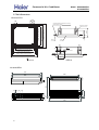
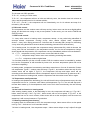
4. Net dimension
AB182ACERA:
:;9
A9
ITL ZPM VITMRC ;>SS
VITMR
KMQRQTO
B>
:A9
><>SS 7JMZ]MMT Y[YVMTYQUT VURMY8
NXMYP IQX PURM
>@9SS 7QTLUUX [TQZ LQSMTYQUT8
?>9SS 7KMQRQTO UVMTQTO LQSMTYQUT8
@99SS 7VITMR LQSMTYQUT8
:=9
GFEH D
GFEH D
AC182ACERA:
620
605
600
880
100
655
40
35
35
30
200
990
10
240
199
900
<;9SS
Y[YVMTYQUT PURLMX
:>9SS
@99SS 7VITMR LQSMTYQUT8
OIY VQVM
?>9SS 7KMQRQTO UVMTQTO LQSMTYQUT8
RQW[QL VQVM
U\MXRIVML LQYZITKM JMZ]MMT ZPM KMQRQTO
>@9SS 7QTLUUX [TQZ LQSMTYQUT8
LXIQTIOM VQVM
?9SS
B9
Commercial Air Conditioner
Model: AB182ACERA
AC182ACERA
5. Installation Instructions
Cassette unit:
Cautions
Do not obstruct or cover the ventilation
grille of the air conditioner. Do not put fingers
or any other things into the inlet/outlet and
swing louver.
Do not allow children to play with the air
conditioner. In no case should children be
allowed to sit on the outdoor unit.
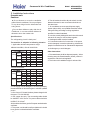
Specifications
The refrigerating circuit is leak-proof.
The machine is adaptive in following situation
1. Applicable ambient temperature range:
AB092/122ACBIA, AB142/182ACBJA:
DB
indoor
WB
Cooling
outdoor DB
WB
indoor DB
Heating
WB
outdoor DB
WB
Rated Maximum Minimum
32
18
C 27
23
14
C 19
C 35
43
-5
C 24
26
-27
15
C 20
--C 14.5
7
24
-7
C
18
-C 6
AB142/182ACBFA:
DB
indoor
WB
Cooling
outdoor DB
WB
DB
Heating indoor
WB
outdoor DB
WB
Rated Maximum Minimum
32
18
C 27
23
14
C 19
43
10
C 35
26
-C 24
27
15
C 20
--C 14.5
7
24
-7
C
6
18
-C
2. If the supply cord is damaged, it must be replaced by
the manufacturer or its service agent or a similar qualified
person.
3. If the fuse on PC board is broken please change it with
the type of T3.15A /250VAC.
4. Use copper wire only. The connecting cable should
2
be H05RN-F 4G 0.75mm. The power cable should be
2
H05RN-F 3G 2.5mm.
All the cables shall have got the European authentication
certificate.
5. The power cord should be self-provided and it should
have got the Local authentication certificate.
11
6. The air breaker should be all-pole switch. And the
distance between it's two connecters should be no
less than 3mm.
7. Air conditioner must use special power supply
system (above 20A), and qualified electrician makes
wiring and fixing according to wiring regulations
specified in national standard.
8. In socket, exactly distinguish earth wire with neutral
wire and it is wrong to connect them together.
9. A leakage breaker must be installed.
10. Connection method is Y-connection .If the power
cord is damaged, it must be replaced by professional
people of manufacturer or its maintenance department
or similar agency to avoid dangers.
Other Instructions
1. The waste battery shall be disposed properly. When
throwing away the waste batteries, please perform in
accordance with the local regulation.
2. The indoor unit installation height is at least 2.5m.
Commercial Air Conditioner
Installation Tools
Installation tools
The installation tools listed in the following sheet
can be used as required.
Model: AB182ACERA
AC182ACERA
The following parts mentioned in this manual
are the installation accessories we prepared.
Symbol
Parts Name
1. Screw driver
2. Hacksaw
A
Adhesive tape
B
Pipe clamp
C
Connecting hose
D
Drainage hose
E
Non-hydroscopic
heat insulating material
F
Gypsum powder
3. Drill with a diameter of 60mm
4. Inner hexagon spanner,shifting
spanner
5. Spanner (14, 17, 19,24,27mm)
6. Pipe cutter
7. Pipe expander
8. Knife
9. Pincers
10. Leakage detector or soapy water
11. Band tape
12. Scraper
13. Refrigerant oil
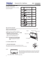
Installation Procedures
1.Selection of Installation Place
(1) Place above the ceiling where it is enough space to arrange the unit.
(2) Place where the drainage pipe can be arranged well.
(3) Place where inlet and outlet air of indoor and outdoor unit will not be blocked.
(4) Do not expose the unit to the place with heavy oil or moisture (e.g.kitchen and workshop).
(5) Do not set the unit in the place where destructive gas (such as sulfuric acid gas) or pungent
gas (thinner and gasoline) concentrates and retains.
(6) Place strong enough to support the unit .
Air outlet
Air inlet
Air outlet
1.5m
1.5m
2.5m Over
12
0.31m
H
(7) No expensive articles such as television and piano below indoor unit.
(8) Enough space for maintenance.
(9) Place more than 1m away from television and radio to avoid disturbing television and radio.
(10) Easy for maintenance.
Commercial Air Conditioner
Model: AB182ACERA
AC182ACERA
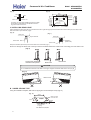
2.Installation Preparation
Overlap between ceiling and
ornament panel shall be 25mm
150mm
Ceiling
Ornament panel
Distance between
suspending bolts 535mm
320mm
Suspending bolts
60mm
Ceiling opening 650mm
Ornament panel 700mm
Indoor unit 570mm
(1) Position of ceiling opening between unit and suspending bolt (front view of unit).
Indoor unit 570mm
Ceiling opening 650mm
Ornament panel 700mm
(2) Prepare all piping (refrigerant,water drainage )and wires (connection wire of remote controller, indoor
unit connection wires) to the indoor unit before installation in order to connect indoor unit immediately
after installation.
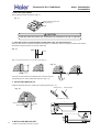
(3) Install a suspending bolt
To support the unit weight ,anchor bolt should be used in the case of
the existing ceiling. For new ceiling, use flush-in type bolt, built-in
type bolt or parts pretared in the field.
Before going on installing, adjust the distance to ceiling.
50 ~150mm
Roof
Anchor bolt
Long nut or thread
Suspending bilt M10
Ceiling
<Installation Example>
Note: All the above mentioned parts shall be prepared in feild, the diameter of suspending bolt is M10
3. Installation of indoor unit
In case of no ceiling
Install unit temporarily
Put suspending bracket on the suspending bolt to hang the unit up. Be sure to use nut and washer at
both end of the breaket to secure firmly.
After installation on the ceiling
(1) Adjust unit to its right position (Refer to preparation for installation-(1))
(2)Check that unit is horizontal.
Water pump and floating switch is installed inside indoor unit,check four corners of the unit for
its lever using horizontal comparator or PVC tube with water.(If unit is tilting against the direction
of water drainage,problem may occur on floating water leakage.)
13
Commercial Air Conditioner
Model: AB182ACERA
AC182ACERA
In the case of existing ceiling
Nut (Prepare in feild)
(1)Install unit temporarily
Washer (Prepared in feild)
Put suspending bracket on the suspending bolt to hang the
unit up.Be sure to use nut and washer at both end of the
bracket to secure it firmly.
(2)Adjust the height and position of the unit.
(3)Proceed with procedure (4) of " In the case of no ceiling "
Suspending bolts
Fasten (double nuts)
Insert
leveler
Washer fixing pad
(prepared in feild)
[ secure the washer firmly]
Polythene pipe
4. Installation of water drainage pipe
(1) Install water drainage pipe
Pipe diameter shall be equal or larger than that of connecting pipe (Pipe of polythene; size: 25mm;
O.D.: 32mm )
Drainpipe should be short, with a downward slope at least 1/100 to prevent air bag from forming.
If downward slope of drainpipe cannot be made,lifting pipe shall be installed.
Keep a distance of 1-1.5m between suspending bolts, to make water hose straight.
1-1.5m
slope over 1/100
Use the drainage hose and clip provided with unit.
Insert water pipe into water plug until it reaches the white tape.
Tighten the clip until head of the screw is less than 4mm from hose.
Wind the drainage hose to the clip using seal pad for heat insulation.
Insulate drainage hose in the room.
Large size seal pad
(accessory)
Clip
Tape(white)
Clip
Draingage hose
4mm below
5. Cautions for the water drainage lifting pipe
Installation height of water drainage lifting pipe shall be less than 280mm
Clip
14
220mm
Drainage hose
500mm below
220
Water drainage
lifting pipe
500mm below
300mm below 1-1.5m Suspending bracket
280mm unter
Drainage hose
75mm below
There should be a right angle with unit ,300mm from unit.
Commercial Air Conditioner
Model: AB182ACERA
AC182ACERA
< Note >
The slope of water drainage hose shall be within 75mm , make the drainage plug not to bear
excessive force.
If several water hoses join together, of as per following procedures.
100mm ¸over
Slope below 1/100
Connection drainage hose with a T-joint
Specifications of the selected drainage hoses shall meet the requirements for the unit running
6. Installation of Ornament Panel
Install ornament panel on indoor unit
(1) Check whether indoor unit is horizontal with leveler or polythene pipe filled with water , and
check that the dimension of the ceiling opening is correct. Take off the lever gauge before
installing the ornament panel.
(2) Fasten the screws to make the height difference between the two sides of indoor unit less than
5mm.
(3) Firstly fix it with screws temporarily.
(4) Fasten the two temporarily fixing screws and other two, and tighten the four screws.
(5) Connect the wires of synchro-motor.
(6) Connect the wire of signal.
(7) If no response of remote controller,check whether the wiring is correct,restart remote controller
10 seconds after shut off power supply.
Electric control box
Panel limitation board installation
(1)Install the panel board in the direction shown in the figure.
(2)The incorrect direction will result in water leakage,meanwhile swing and signal receiving are displayed
that cannot be connected.
Piping Connection
Flare connection
Gas pipe
3-way valve
Indoor
Unit
Outdoor
unit
Liquid
pipe
2-way valve
Flare connection
15
Commercial Air Conditioner
7.3 Convertible indoor unit
Standard accessories:
The following installation parts are furnished.
Use them as required.
No.
1
Model: AB182ACERA
AC182ACERA
Accessory parts
Qty.
1
Remote controller
2
2
Battery
3
Wire clamp
4
Heat
insulation
sheathing
1+1
5
Screw
2+2
6
Screw cap
1+1
7
Remote
controller
bracket
1
4
Pipe connection requirement
Please refer to the specification to confirm the stop valve diameter and the permitted pipe drop and pipe length.
INSTALLATION PROCEDURE
Install the room air conditioner as follows:
(Fig. 1)
Machine screw
Tapping screw
PREPARING INDOOR UNIT INSTALLATION
Tapping screw
1. REMOVE THE INTAKE GRILL
Open the intake grill and remove the
three or four or six screws.(Fig. 1)
Remark: The main unit can be wired before
the indoor unit is installed. Select
the most appropriate installation
order.
Intake grill
A. FLOOR CONSOLE TYPE
(Fig. 2)
1. DRILLING FOR PIPING
rear
Select piping and drain directions.(Fig.2) (Series14,18,24)
The piping and drain can be made in three directions as shown below.
right
down
(Fig.3)
When the directions are selected, drill a 7 cm dia. hole on the wall so
that the hole is tilted downward toward the outdoor for smooth water
flow. When the pipe is led out from the rear, make a hole in Fig.6, at
the position shown.
Drain hose (Left side)
16
Drain hose (Right side)
Commercial Air Conditioner
(Fig. 4)
Model: AB182ACERA
AC182ACERA
(Fig. 5)
Wall
99cm
50cm
6mm
10cm
24.5cm
Wall bracket
Side of set
6.5cm
For series 14,18,24 when installing set to wall, install
the accessory wall bracket at the position shown in
Fig.5,and mount the set to it.
7cm hole
6.5cm
65.5cm
outdoor unit
53cm
4.5cm
Indoor unit
3.5cm hole
12.5cm
10cm
2. INSTALLING DRAIN HOSE
Select whether the drain hose will be connected to the left or right side.(Fig.3) Insert the drain hose into the drain pan, then secure the
drain hose with a nylon fastener. (Fig.6)
(Fig. 6)
(Fig. 7)
Drain pan
Drain pan
Nylon fastener
Drain hose
Insulation
(Drain hose)
Drain hose
Wrap the insulation (drain hose) around the drain hose connection.(Fig.7)
Be sure to arrange the drain hose correctly so that it is leveled lower than the drain hose connecting port of the indoor unit.
(Fig. 8)
OK
NO
Arrange the drain hose
lower than this portion.
NO
Drain hose
Drain hose
CAUTION
Do not install the unit drain hose side is too high. Height A should be less than 5 mm.(Fig.9)
(Fig. 9)
Drain hose
A
A
B. UNDER CEILING TYPE
Using the installation template, drill holes for piping and anchor bolts(for holes).(Fig.10)
(Fig. 10)
200mm
900mm
Installation
template
Drilling position
for piping
For series 14,18,24
17
Drilling position
for anchor bolt
Ceilling
Wall
Commercial Air Conditioner
Model: AB182ACERA
AC182ACERA
1. DRILLING FOR PIPING
Select piping and drain directions. (Fig.11)
(Fig. 11)
Rear (Install the drain hose
in the direction.)
Right
CAUTION
Install the drain hose at the rear; it should not be installed on the top or right side.
2. DRILLING HOLES FOR ANCHOR BOLTS AND INSTALLING THE ANCHOR BOLTS
When the directions are selected, drill 80mm and 50mm or 150mm dia. hole on the wall so that the hole is tilted
downward toward the outdoor for smooth water flow.
(Fig. 12)
Wall
6mm
With a concrete drill, drill four 12.7 mm dia. Holes.(Fig.12)
60 to 70mm
(Fig. 13)
12.7mm
Insert the anchor bolts into the drilled holes, and drive the pins
completely into the anchor bolts with a hammer. (Fig. 13)
3. INSTALLING BRACKETS
Install the brackets with nuts, washers and spring washers.(Fig. 14)
Bracket (Left)
(Fig. 14)
Bracket (Right)
For series 14,18,24
381
26.5
2-R2.5
18
5
10
Bracket
16 21 28
4-R
Special nut
68
7.5
Spring washer
26.5
232
10
5
4-R
2-R2.5
7.5
18
232
26.5
18
4. INSTALLING INDOOR UNIT
Reset the hex bolts as shown in Fig.15.
26.5
381
28 21 16
68
Commercial Air Conditioner
(Fig. 15)
Model: AB182ACERA
AC182ACERA
Hex bolt
Indoor unit
8 to 13mm
(Fig. 16)
Apply the indoor unit to the brackets.(Fig.16)
Bolt
Bracket
Indoor unit
Now, securely tighten the hex bolts in both sides.
5. INSTALL THE DRAIN HOSE
Select whether the drain hose will be connected to the left or right side.(Fig.3)
Insert the drain hose into the drain pan, then secure the drain hose with a nylon fastener.(Fig.6)
Wrap the insulation (drain hose)around the drain hose connection.(Fig.7)
Be sure to arrange the drain hose correctly so that it is leveled lower than the drain hose connecting port of the
indoor unit.(Fig.8)
(Fig. 17)
Remove the hole cover.
Arrange the drain hose
lower than this portion
Drain hose
OK
NO
When drain hose is arranged backward. Secure the drain hose with the VT wire. (Fig. 18)
(Fig. 18)
Piping hole
Base (Bottom)
VT wire hole
Intake grill
Pass the drain hose through here
For series 14,18,24
Cut the grill
GAS LEAKAGE INSPECTION
CAUTION
After connecting the piping, check the joints for gas leakage with leakage detector.
HOW TO CONNECT WIRING TO THE TERMINALS
A. For solid core wiring (or F-cable)(Fig.19A)
19
(1) Cut the wire with a wire cutter or wire-cutting pliers, then strip the insulation to about 25mm of the exposed solid
wire.
(2) Using a screwdriver, remove the terminal screw(s) on the terminal board.
(3) Using pliers, bend the solid wire to form a loop suitable for the terminal screw.
(4) Shape the loop wire properly, place it on the terminal board and tighten securely with the terminal screw using
a screw driver.
Commercial Air Conditioner
Model: AB182ACERA
AC182ACERA
B. For strand wiring(Fig.19B)
(1) Cut the wire with a wire cutter or wire-cutting pliers, then strip the insulation to about 10mm of the exposed strand wiring.
(2) Using a screwdriver, remove the terminal screw(s)on the terminal board.
(3) Using a round terminal fastener or pliers, securely clamp a round terminal to each stripped wire end.
(4) Position the round terminal wire, and replace and tighten the terminal screw using a screw driver.
Strip 25mm
A. Solid wire
B. Strand wire
Loop
Insulation
Strip 10mm
(Fig. 19)
Screw with
special washer
Round
terminal
Terminal
board
Wire
Round
terminal
Screw with
special washer
Round
terminal
Wire
HOW TO FIXED CONNECTION CORD AND POWER CABLE AT THE CORD CLAMP
After passing the connection cord and power cable through the insulation tube, fasten it with the cord clamp, as
shown in Fig.20
(Fig. 20)
Insulation tube
Cord clamp
Use VW-1, 0.5 to 1.0 mm thick, PVC tube as the insulation tube.
ELECTRICAL WIRING
CAUTION
(1) Match the terminal block numbers and connection cord colors with those of the
outdoor unit.
Erroneous wiring may cause burning of the electric parts.
(2) Connect the connection cords firmly to the terminal block. Imperfect installation
may cause a fire.
(3) Always fasten the outside covering of the connection cord with the cord clamp.
(If the insulator is chafed, electric leakage may occur.)
(4) Always connect the ground wire.
20
Commercial Air Conditioner
Model: AB182ACERA
AC182ACERA
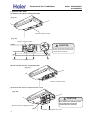
1. INDOOR UNIT SIDE
(1) Remove the electric component box.
(Fig. 21)
Electric component box
(Fig. 22)
Electric component box
CAUTION
Do not remove the screws. If the
screws are removed, the electric
component box will fall.
Remove the four tapping screws.
(2) Pull out the electric component box.
(Fig. 23)
Electric component box
(3) Remove the electric component box cover.
(Fig. 24)
CAUTION
Remove the three tapping screws.
Base
21
Be careful not to pinch the lead
wires between the electric
component box and base.
Electric component box cover
Commercial Air Conditioner
Model: AB182ACERA
AC182ACERA
(4) Wiring
(1) Remove the cord clamp.
(2) Process the end of the connection cords to the dimensions shown in Fig.25.
(3) Connect the end of the connection cord fully into theterminal block.
(4) Fasten the connection cord with a cord clamp.
(5) Fasten the end of the connection cord with the screw.
ELECTRICAL WIRING
WARNING
(1) Always use a special branch circuit and install a special receptacle to supply power to the
room air conditioner.
(2) Use a circuit breaker and receptacle matched to the capacity of the room air conditioner.
(3) The circuit breaker is installed in the permanent wiring. Always use a circuit that can trip all
the poles of the wiring and has an isolation distance of at least 3mm between each pole.
(4) Perform wiring work in accordance with standards so that the room air conditioner can be
operated safely and positively.
(5) Install a leakage circuit breaker in accordance with the related laws and regulations and
electric company standards.
CAUTION
(1) The power source capacity must be the sum of the room air conditioner current and the current
of other electrical appliances. When the current contracted capacity is insufficient, change the
contracted capacity.
(2) When the voltage is low and the air conditioner is difficult to start, contact the power company
the voltage raised.
TEST RUNNING
1. CHECK ITEMS
(1) INDOOR UNIT
(1) Is operation of each button on the remote control unit normal?
(2) Does each lamp light normally?
(3) Do not air flow direction louvers operate normally?
(4) Is the drain normal?
(2) OUTDOOR UNIT
(1) Is there any abnormal noise and vibration during operation?
(2) Will noise, wind, or drain water from the unit disturb the neighbors?
(3) Is there any gas leakage?
CUSTOMER GUIDANCE
Explain the following to the customer in accordance with the operating manual:
(1) Starting and stopping method, operation switching, temperature adjustment, timer, air flow switching, and other
remotecontrol unit operations.
(2) Air filter removal and cleaning, and how to use air louvers.
(3) Give the operating and installation manuals to the customer.
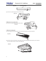
MOUNT THE COVER PLATE AND THE INTAKE GRILL
Note: The following installing procedure only for series 14,18,24
1.Mount the cover plate. (Right)
(1) Cut a pipe exit hole in the right plate. This is only when the pipe exits from the right side. (This operation is not
required when the protrusion is on the top or rear.)
22
Commercial Air Conditioner
(Fig. 26)
Model: AB182ACERA
AC182ACERA
Cover plate (Right)
(2) Join the cover plates (right) and mount with screws.
(Fig. 27)
2. Mount the cover plate.(Left)
Cover plate (Left)
(1) Join the cover plate (left) and mount with screws.
(Fig. 28)
3. Mount the intake grill.
(1) Cut the right side of the intake grill. This is only when the pipe exits from the right side
(Fig. 29)
(2) Insert the hinges on the bottom of the intake grill into the holes in the base assembly. Then mount the
arms to the three areas on the top of the intake grill.
(Fig.30)
23
Commercial Air Conditioner
Model: AB182ACERA
AC182ACERA
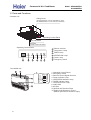
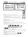
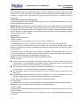
6. Parts and Functions
:J[[N\\N ]WR\8
F_RWP UX]^NZ
+9RZ OUX_ MRZNL\RXW LJW KN JMS][\NM K` ][RWP
\QN FI?B> K]\\XW XW \QN ZNVX\N LXW\ZXUUNZ,
CYNZJ\RWP :XW\ZXU DJWNU
9RZ ?WUN\ >ZRUUN
9RZ =RU\NZ
+?W[RMN XO \QN ?WUN\ >ZRUUN,
CYNZJ\RWP :XW\ZXU DJWNU
a ENVX\N ZNLNR^NZ
b :XVYZN[[XZ @JVY
c G?A<E @JVY
:CAD G?A<E
d CD<E9G?CB @JVY
CD<E DCI<E <A<E
e DX_NZ @JVY
a
b
c
d
e
f <VNZPNWL` [_R\LQ
f
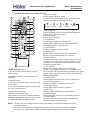
:XW^NZ\RKUN ]WR\8
/.
//
/
DCI<E
CD<E
G?A<E
1
7
6
24
d
e
f
:CAD
g
<A<E
b
c
/ CYNZJ\RWP :XW\ZXU DJWNU
0 <VNZPNWL` [_R\LQ
1 ENVX\N :XW\ZXU FRPWJU ENLNR^NZ
2 DX_NZ ?WMRLJ\XZ @JVY
3 CD<E9G?CB ?WMRLJ\XZ @JVY
4 G?A<E ?WMRLJ\XZ @JVY
5 :XVYZN[[XZ E]W @JVY
6 ?W\JTN >ZRUU
7 9RZ =RU\NZ
/. HY-;X_W 9RZ ;RZNL\RXW =UJY[
// ERPQ\-@NO\ 9RZ ;RZNL\RXW @X]^NZ[
+KNQRWM HY-;X_W 9RZ ;RZNL\RXW =UJY[,
Commercial Air Conditioner
Model: AB182ACERA
AC182ACERA
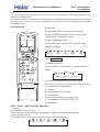
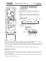
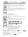
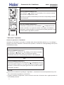
7. Infrared controller functions-YR-H71
v|
v}
v{
wt
vz
wu
vy
B
A
vx
vw
vv
wv
ww
wx
G
X
W
S
wy
vu
SLL
vt
wz
u
u}
SEMP
ON
OFF
v
RUING
w
MODE
x
HEALSH
y
z
{
FAN
RLEEP
FQERH
RES
SIMEQ
HIGH4RO
QERES
CODE
u{
uz
CLOCK
FILSEQ
|
u|
uy
ux
uw
LIGHS
LOCK
}
uv
uu
ut
A>WKQT V`nndib Honnji
-Tj\[ kf j\k k\dg\iXkli\3 R\kk`e^ iXe^\j?
6; C kf 85 C.
Ie Tg4Dfne ]leZk`fe1 ]fi Zfekifcc`e^ lg Xe[
[fne ]`ck\i3
73RUING Blkkfe
I] pfl gi\jj k_`j Ylkkfe feZ\1 Xlkf jn`e^ n`cc
Y\ XZk`mXk\[3
I] pfl gi\jj k_`j Ylkkfe X^X`e1 k_\ cflm\i n`cc
]`o `e k_\ gi\j\ek gfj`k`fe3
83Pfn\i ON4OFF Blkkfe
Tj\[ ]fi le`k jkXik Xe[ jkfg
A]k\i gfn\i fe1 k_\ LCD f] i\dfk\ Zfekifcc\i
n`cc [`jgcXp k_\ gi\m`flj fg\iXk`fe jkXk\ -\oZ\gk
]fi SIMEQ1RLEEP Xe[ RUING jkXk\.3
93Og\iXk`fe MODE
Tj\[ kf j\c\Zk fg\iXk`fe df[\3
Em\ip k`d\ pfl gi\jj MODE Ylkkfe1 fg\iXk`fe df[\
Z_Xe^\j XZZfi[`e^ kf ]fccfn`e^ j\hl\eZ\?
ATSO
COOL
DQW
HEAS
FAN
:3HEALSH Blkkfe
Tj\[ kf j\k _\Xck_ df[\1 `] k_\ le`k _Xj k_\ e\^Xk`m\ `fe
]leZk`fe Xe[ fop^\e YXi ]leZk`fe3
;3CLOCK Blkkfe
Tj\[ kf j\k Zfii\Zk k`d\3
<3CLOCK Blkkfe
Tj\[ kf j\c\Zk SIMEQ ON1 SIMEQ OFF3
-Nfk\? `] k`d\ f] SIMEQ ON `j k_\ jXd\ Xj SIMEQ
OFF1SIMEQ ON4OFF ZXeefk Y\ j\k.
=3 FILSEQ Blkkfe
Tj\[ kf j\k lg4[fne ]leZk`fe f] ]`ck\i3
>3 CODE Blkkfe
Tj\[ kf j\c\Zk Zf[\ A fi B1 ]fi k_\ le`kj \oZ\gk
k_Xk n\ i\Zfdd\e[ \jg\Z`Xccp1 k_\ Zf[\ `j A3
653QERES Blkkfe
Pi\jj k_`j Ylkkfe Yp lj`e^ X j_Xig Xik`Zc\ kf i\jld\
k_\ Zfii\Zk fg\iXk`fe f] k_\ i\dfk\ Zfekifcc\i `e ZXj\
f] e\\[1 `3\3 ]fi \oXdgc\ `e ZXj\ f] dXc]leZk`fej [l\
kf \c\ZkifdX^e\k`Z ef`j\3
663LOCK Blkkfe
Tj\[ kf cfZb fg\iXk`fe Ylkkfe Xe[ LCD [`jgcXp
Zfek\ekj? Yp gi\jj`e^ k_`j Ylkkfe1 fk_\i Ylkkfej Zfd\j
flk f] ]leZk`fe Xe[ cfZb jkXk\ [`jgcXp Xgg\Xij@ `] pfl gi\jj
`k X^X`e1 cfZb jkXk\ n`cc Y\ ef dfi\ XZk`m\ Xe[ cfZb jkXk\
[`jgcXp n`cc [`jXgg\Xi3
673LIGHS Blkkfe
Tj\[ kf c`^_k k_\ Zfekifc gXe\c -fecp ]fi ZXY`e\k le`k.
683Tg Xe[ [fne Blkkfe
Tj\[ kf j\k SIMEQ Xe[ CLOCK lg fi [fne3
693HIGH4RO Blkkfe
Tj\[ kf j\c\Zk HIGH fi ROFS fg\iXk`fe3
6:3RES Blkkfe
Tj\[ kf Zfe]`id SIMEQ Xe[ CLOCK j\kk`e^j3
6;3FQERH Blkkfe
Tj\[ kf j\k ]i\j_ df[\1 k_\ le`k n`cc [iXn `e ]i\j_ X`i3
6<3RLEEP Blkkfe
-S_\ ZcfZb dljk Y\ Zfii\Zk\[ Y\]fi\ j\kk`e^ jc\\g
]leZk`fe. Tj\[ kf j\k jc\\g df[\3
RSWKE 63Cffc`e^ fecp X`i Zfe[`k`fe\i [f\j efk _Xm\ k_\ [`jgcXpj Xe[ ]leZk`fej i\cXk\[ kf _\Xk`e^3
73HIGH4RO Ylkkfe
S_`j Ylkkfe `j XZk`mXk\[ `e Cffc`e^4H\Xk`e^ df[\1 k_\ ]Xe jg\\[ `j `e ATSO df[\ X]k\i
gi\jj`e^ `k Xe[ +_`^_ ]leZkfe+ n`cc Y\ ZXeZ\cc\[ XlkfdXk`ZXccp X]k\i 6: d`elk\j ilee`e^3
25
Commercial Air Conditioner
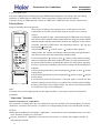
6=3FAN Blkkfe
Tj\[ kf j\c\Zk ]Xe jg\\[?LOU1MID1HIGH1ATSO3
DQW QTN
HEAS QTN
FAN QTN
873RLEEP RkXk\ D`jgcXp
883BASSEQW Ee\i^p D`jgcXp
Nfk`]p k_\ lj\i n_\e `k `j k`d\ kf Z_Xe^\
k_\ YXkk\i`\j3
893LOCK RkXk\ D`jgcXp
8:3FAN RPEED D`jgcXp
LO
MID
HI
~431
ATSO
8;3SIMEQ ON D`jgcXp
U`hjn` Ijinljgg`l8 Sk`l\ndji
U_\e `e lj\1 [`i\Zk j`^eXc kiXejd`jj`fe
_\X[ kf k_\ i\Z\`m\i gcXZ\[ fe k_\ `e[ffi
le`k
Q\dfm\ k_\ YXkk\ip ZfdgXikd\ek c`[
Rc`^_kcp gi\jj Xe[ [`j\e^X^\ k_\ YXkk\ip ZfdgXikd\ek
c`[ dXib\[ n`k_ + + Xe[ k_\e _fc[ k_\ i\dfk\
Zfekifcc\i Yp k_\ lgg\i j\Zk`fe Xe[ k_\e i\dfm\
k_\ YXkk\ip ZfdgXikd\ek c`[ Yp gi\jj`e^ `e k_\ [`i\Zk`fe
f] k_\ Xiifn Xj j_fne `e k_\ ]`^li\ XYfm\3
Pj\_dib nc` ]\nn`ls
Eejli\ k_Xk YXkk\i`\j Xi\ Zfii\Zkcp gcXZ\[ `e k_\ Zfd
2gXikd\ek Xj i\hl`i\[ ]fi gfj`k`m\ Xe[ e\^Xk`m\ k\i
2d`eXcj3
U`kg\^dib nc` ]\nn`ls ^jhk\lnh`in gd_
S_\ YXkk\ip ZfdgXikd\ek c`[ `j i\`ejkXcc\[ `e k_\
i\m\ij\ j\hl\eZ\3
Jdmkg\s l`pd`q
Pi\jj k_\ Ylkkfe kf j\\ `] YXkk\i`\j Xi\ gifg\icp ]`kk\[3
I] ef [`jgcXp Xgg\Xij1 i\]`k k_\ YXkk\i`\j3
Cfe]`idXk`fe `e[`ZXkfi
I] ef `e[`ZXk`fe `j [`jgcXp\[ X]k\i gi\jj ON4OFF Ylkkfe1
i\cfX[ k_\ YXkk\i`\j3
CXlk`fe?
I] k_\ i\dfk\ Zfekifcc\i [f\j efk fg\iXk\ Xj [\j`^e\[
X]k\i ]`kk`e^ e\n YXkk\i`\j f] k_\ jXd\ kpg\1 gi\jj
k_\ Q\j\k Ylkkfe -dXib\[ . n`k_ X gf`ek\[ Xik`Zc\3
Igj^f V`n
U_\e le`k `j jkXik\[ ]fi k_\ ]`ijk k`d\ Xe[ X]k\i i\gcXZ`e^ YXkk\i`\j `e i\dfk\
Zfekifcc\i1 ZcfZb j_flc[ Y\ X[aljk\[ Xj ]fccfnj?
63Pi\jj CLOCK Ylkkfe1 ZcfZb `e[`ZXk`fe f] + AM + fi + PM + ]cXj_\j3
73Pi\jj
fi
kf j\k Zfii\Zk k`d\3 EXZ_ gi\jj n`cc `eZi\Xj\ fi [\Zi\Xj\
6 d`e3 I] k_\ Ylkkfe `j b\gk gi\jj\[1 k`d\ n`cc `eZi\Xj\ fi [\Zi\Xj\ hl`Zbcp3
83A]k\i k`d\ j\kk`e^ `j Zfe]`id\[1 gi\jj +RES+ ? AM fi PM jkfg ]cXj_`e^1
n_`c\ ZcfZb jkXikj nfib`e^3
Nfk\?AM d\Xej dfie`e^ Xe[ PM d\Xej X]k\ieffe3
26
v
COOL QTN
BXkk\ip cfX[`e^
BXkk\i`\j Xi\ ]`kk\[ Xj ]fccfnj?
v
ATSO QTN
BXkk\ip cfX[`e^
v
863Og\iXk`fe MODE D`jgcXp
S_\ [`jkXeZ\ Y\kn\\e k_\ i\dfk\ Zfekifcc\i Xe[
k_\ i\Z\`m\i j_flc[ Y\ dXo <d Xe[ k_\i\ j_flc[ Y\
ef fYjkXZc\ Y\kn\\e k_\d3
Df efk k_ifn k_\ i\dfk\ Zfekifcc\i@ gi\m\ek `k
]ifd Y\`e^ [XdX^\[3
U_\e fg\iXk`e^ k_\ i\dfk\ Zfekifcc\i `e Xe
Xi\X n_\i\ \c\Zkife`ZXccp Zfekifcc\[ c`^_kj Xi\
`ejkXcc\[ fi n`i\c\jj _Xe[j\kj Xi\ lj\[1 gc\Xj\ dfm\
Zcfj\i kf k_\ `e[ffi le`k Xj k_\ ]leZk`fe f] k_\ i\dfk\
Zfekifcc\i d`^_k Y\ X]]\Zk\[ Yp j`^eXcj \d`kk\[
Yp k_\ XYfm\ d\ek`fe\[ \hl`gd\ekj3
v
6>3SIMEQ OFF D`jgcXp
753CLOCK D`jgcXp
763FILSEQ D`jgcXp
773SEMPEQASTQE D`jgcXp
783ATSO RUING D`jgcXp
793HIGH4RO D`jgcXp
7:3RIGNAL RENDING D`jgcXp
7;3FQERH AIQ D`jgcXp
7<3ELECSQICAL HEASING D`jgcXp
7=3Rfd\ fk_\i Ylkkfej
Acc k_\j\ ]leZk`fej Xi\ efk XmX`cXYc\ efn3
7>3HEALSH D`jgcXp
D`jgcXpj n_\e _\Xck_p ile ]leZk`fe `j j\k3
853DEHTMIDIFICASION D`jgcXp
Model: AB182ACERA
AC182ACERA
MODE
HEALSH
RLEEP
FQERH
RES
CLOCK
u SIMEQ
v
HIGH4RO
FILSEQ
QERES
CODE
LIGHS
LOCK
w
Commercial Air Conditioner
Model: AB182ACERA
AC182ACERA
Nfk\?
Ik `j i\Zfdd\e[\[ k_Xk k_\ YXkk\i`\j Y\ i\dfm\[ ]ifd k_\ ZfdgXikd\ek `] k_\ i\dfk\ Zfekifcc\i `j efk
lj\[ ]fi Xe \ok\e[\[ g\i`f[3
S_\ i\dfk\ Zfekifcc\i `j gif^iXdd\[ ]fi XlkfdXk`Z k\jk f] fg\iXk`fe df[\ X]k\i k_\ YXkk\i`\j Xi\ i\gcXZ\[3
U_\e k_\ k\jk `j Zfe[lZk\[1 Xcc `Zfej n`cc Xgg\Xi fe k_\ jZi\\e Xe[ k_\e [`jXgg\Xi `] k_\ YXkk\i`\j
Xi\ gifg\icp ]`kk\[3
L\i Sk`l\ndji
63Te`k jkXik
Pi\jj ON4OFF Ylkkfe kf jkXik pfli X`i Zfe[`k`fe\i3
Pi\m`flj fg\iXk`fe jkXklj Xgg\Xij fe LCD -\oZ\gk ]fi
A
SIMEQ1 RLEEP1 Xe[ RUING j\kk`e^.3
73R\c\Zk fg\iXk`e^ df[\
Pi\jj MODE Ylkkfe3 Ak \XZ_ gi\jj1 fg\iXk`fe df[\
G
X
W
S
Z_Xe^\j Xj ]fccfnj?
SEMP
RUING
x
MODE
v
COOL
ATSO
ON
OFF
u
FAN
RLEEP
w
RES
SIMEQ
HIGH4RO
HEAS
FAN
S_\e j\c\Zk FAN
83 A[aljk ]Xe jg\\[
HEALSH FQERH
CLOCK
DQW
Pi\jj FAN Ylkkfe3 Ak \XZ_ gi\jj1 ]Xe jg\\[ Z_Xe^\j Xj
]fccfnj?
FILSEQ
LOU
QERES CODE
MID
HIGH
LIGHS LOCK
A`i Zfe[`k`fe\i n`cc ile Xk k_\ j\c\Zk\[ ]Xe jg\\[3
U_\e `e ATSO df[\1 le`k n`cc X[aljk ]Xe jg\\[ XZZfi[`e^
kf iffd k\dg\iXkli\ XlkfdXk`ZXccp3
93 Te`k jkfg
Pi\jj ON4OFF Ylkkfe kf jkfg le`k3
AYflk FAN df[\
U_\e k_\ X`i Zfe[`k`fe\i ilej `e FAN df[\1
`k `j efk gfjj`Yc\ kf j\c\Zk ATSO FAN fi kf
j\k k\dg\iXkli\3
GXWS< ISSP < NKGW \i_ JU[ Sk`l\ndji
63 Te`k jkXik
Pi\jj ON4OFF Ylkkfe1le`k jkXikj3
Pi\m`flj fg\iXk`fe jkXklj Xgg\Xij fe LCD -\oZ\gk ]fi SIMEQ1RLEEP Xe[ RUING j\kk`e^.
73R\c\Zk fg\iXk`fe df[\
Pi\jj MODE Ylkkfe3 Ak \XZ_ gi\jj1 fg\iXk`fe df[\ Z_Xe^\j Xj ]fccfnj?
27
~431
*11/
+25
.,~3
-~0
Commercial Air Conditioner
Model: AB182ACERA
AC182ACERA
S_\e j\c\Zk ATSO ile fi j\c\Zk COOL fg\iXk`fe fi
j\c\Zk DQW fg\iXk`fe fi j\c\Zk HEAS fg\iXk`fe
83S\dg\iXkli\ j\kk`e^
Pi\jj SEMP Ylkkfe3
A
Em\ip k`d\ k_\ Ylkkfe `j gi\jj\[1 k\dg3 j\kk`e^ `eZi\Xj\j
6 C@ `] k_\ Ylkkfe `j b\gk gi\jj\[1 k\dg3 j\kk`e^ n`cc `eZi\Xj\
hl`Zbcp3
G
X
W
S
Em\ip k`d\ k_\ Ylkkfe `j gi\jj\[1 k\dg3 j\kk`e^ [\Zi\Xj\j
6 C1 `] k_\ Ylkkfe `j b\gk gi\jj\[1 k\dg3 j\kk`e^ n`cc [\Zi\Xj\
hl`Zbcp3
SEMP
w
RUING
y
ON
OFF
w
u
x
RLEEP
MODE
v HEALSH
FAN
RES
SIMEQ
HIGH4RO
FILSEQ
CODE
LIGHS
G
X
W
S
ATSO
FQERH
CLOCK
QERES
R\k gifg\i k\dg\iXkli\
93A[aljk FAN Ylkkfe
Pi\jj FAN Ylkkfe3 Ak \XZ_ gi\jj1 ]Xe jg\\[ Z_Xe^\j Xj ]fccfnj?
LOCK
LOU
MID
HIGH
A`i Zfe[`k`fe\i n`cc ile Xk k_\ j\c\Zk\[ ]Xe jg\\[3
:3 Te`k jkfg
Pi\jj ON4OFF Ylkkfe1le`k jkfgj3
COOL fg\iXk`fe jkXikj
n_\e iffd k\dg3`j
_`^_\i k_Xe k\dg3
j\kk`e^3
TckiX2cfn X`i ]cfn
S\dg3 j\kk`e^ 07 C
S\dg3j\kk`e^
Oe i\XZ_`e^ k\dg3j\kk`e^
07 C1 le`k n`cc ile `e d`c[
DQW df[\3
Ie ASTO df[\1 k_\ k\dg\iXkli\ j\kk`e^ `j efk [`jgcXp\[ fe LCD3 Ie k_`j df[\1 [li`e^ ilee`e^ X`i Zfe[`k`fe\i
n`cc j\c\Zk COOL1 HEAS fi FAN df[\ XlkfdXk`ZXccp XZZfi[`e^ kf k_\ iffd k\dg\iXkli\3
Ie DQW df[\1 n_\e iffd k\dg\iXkli\ Y\Zfd\j 7 C _`^_\i k_Xe k\dg\iXkli\ j\kk`e^1 le`k n`cc ile `ek\id`kk\ekcp
Xk LOU jg\\[ i\^Xi[c\jj f] FAN j\kk`e^3 U_\e iffd k\dg\iXkli\ `j cfn\i k_Xe k\dg\iXkli\ j\kk`e^1 le`k n`cc
fecp ile FAN fg\iXk`fe3
Ie HEAS df[\1nXid X`i n`cc Ycfn flk X]k\i X j_fik g\i`f[ f] k`d\ [l\ kf Zfc[2[iX]k gi\m\ek`fe ]leZk`fe3
G_eomndib \dl agjq _dl`^ndji
ATSO RUING
Pi\jj RUING Ylkkfe3Tg Xe[ [fne X`i]cfn mXi`\j lgnXi[j Xe[ [fnenXi[j3 L\]k Xe[ i`^_k X`i]cfn mXi`\j
c\]k Xe[ i`^_k j`[\j3 U_\e k_\ XlkfdXk`Z jn`e^ cflm\i dfm\j kf k_\ gifg\i Xe^c\1 gi\jj RUING Ylkkfe
ZXe ]`o k_\ X`i]cfn [`i\Zk`fe3
AcnXpj lj\ RUING Ylkkfe fe k_\ i\dfk\ Zfekifcc\i kf X[aljk ]cXgj3 A[aljk`e^ k_\d Yp _Xe[ dXp i\jlck
`e X`i Zfe[`k`fe\i,j XYefidXccp ilee`e^3
28
Commercial Air Conditioner
A
SEMP
ON
OFF
HEALSH
FAN
RLEEP
MODE
FQERH
CLOCK
RES
SIMEQ
HIGH4RO
FILSEQ
QERES
CODE
LIGHS
Ie COOL fi DQW df[\1 [f efk c\Xm\ k_\ cflm\i `e [fnenXi[ gfj`k`fe ]fi
X cfe^ k`d\1 Xj k_\ nXk\i mXgfi Zcfj\ kf k_\ ^i`cc\ dXp Zfe[\ej\ Xe[ nXk\i
dXp [ifg ]ifd k_\ X`i Zfe[`k`fe\i3
Pc\Xj\ ZXi\]lccp j\k k\dg\iXkli\ n_\e Z_`c[i\e1 fc[ fi n\Xb g\fgc\ lj\
k_\ X`i Zfe[`k`fe\i3
Ie ZXj\ f] ^i\Xk _ld`[`kp1 I] k_\ m\ik`ZXc ]cXgj Xi\ Zfdgc\k\cp klie\[
kfnXi[j c\]k fi i`^_k1 k_\ cflm\i n`cc [ifg nXk\i3
G
X
W
S
RUING
Model: AB182ACERA
AC182ACERA
N\m\i X[aljk k_\ cflm\i [`i\Zkcp Yp _Xe[1 Xj k_`j Zflc[ dXb\ `k nfib
XYefidXccp3I] k_\ cflm\i nfib XYefidXccp1 jkfg le`k1 i\jkXik Xe[ X[aljk k_\
cflm\i Yp i\dfk\ Zfekifcc\i3
Gan`l oidn mnjkmE
D`jgcXpj fe k_\ LCD [`jXgg\Xi3
Acc `e[`ZXkfij fe k_\ `e[ffi le`k ^f flk3
Rn`e^ cflm\i XlkfdXk`ZXccp Zcfj\ k_\ X`i flkc\k3
LOCK
NdinmE
Aj `e COOL df[\ X`i ]cfnj [fnenXi[j1 X[aljk`e^ X`i]cfn _fi`qfekXccp n`cc
Y\ dlZ_ dfi\ _\cg]lc ]fi X Y\kk\i X`i Z`iZlcXk`fe Aj `e HEAS df[\ X`i ]cfnj
lgnXi[j1 X[aljk`e^ X`i]cfn [fnenXi[ n`cc Y\ dlZ_ dfi\ _\cg]lc ]fi X Y\kk\i
X`i Z`iZlcXk`fe3 B\ ZXi\]lc efk kf ZXkZ_ X Zfc[ n_\e Zfc[ X`i Ycfnj [fnenXi[
[`i\Zkcp3
Vg``k Loi^ndji
B\]fi\ ^f`e^ kf Y\[ pfl ZXe gi\jj [fne k_\ RLEEP Ylkkfe Xe[ k_\ X`i Zfe[`k`fe\i n`cc ile jf Xj kf
dXb\ pfl jc\\g dfi\ Zfd]fikXYcp3 B\]fi\ lj`e^ k_`j ]leZk`fe1 k_\ ZcfZb dljk Y\ j\k3
Xm` ja VPKKT aoi^ndji
A]k\i k_\ le`k,j jkXik1 j\k ilee`e^ df[\ Xe[ k_\e gi\jj RLEEP Ylkkfe feZ\ kf dXb\ k_\ X`i Zfe[`k`fe\i
_Xm\ k_\ gi\m`flj2j\k jc\\g k`d\ -]`ijk gfn\i2fe `j +6_+.3 S_\ jc\\g jpdYfc n`cc Xgg\Xi3
4 ? Pi\jj k`d\ Ylkkfe1 pfl ZXe Z_ffj\ k_\ k`d\ `e 6r= _flij3 EXZ_ k`d\ k_\ Ylkkfe `j gi\jj\[1 k_\ k`d\
`eZi\Xj\j4[\Zi\Xj\j 6 _fli? +o_+ Xe[ +OFF+ `e[`ZXk`fej Xgg\Xi fe k_\ [`jgcXp3
Og\iXk`fe Mf[\
63Ie COOL1 DQW df[\
Oe\ _fli X]k\i jc\\g`e^ fg\iXk`fe jkXik1 k_\ k\dg\iXkli\ `j 6 C _`^_\i k_Xe k_\ j\kk`e^ fe\3 A]k\i Xefk_\i
_fli1 k\dg\iXkli\ i`j\j 6 C? jc\\g ile Zfek`elfljcp ]fi Xefk_\i ; _flij Xe[ k_\e jkfgj3 S_\ XZklXc
k\dg\iXkli\ `j _`^_\i k_Xe k_\ j\kk`e^ fe\ n_`Z_ `j kf gi\m\ek ]ifd Y\`e^ kff Zfc[ kf pfli jc\\g3
73Ie HEAS df[\
Oe\ _fli X]k\i jc\\g`e^ fg\iXk`fe jkXik1 k_\ k\dg\iXkli\ `j 7 C cfn\i k_Xe k_\ j\kk`e^ fe\3 A]k\i Xefk_\i
_fli1 k\dg\iXkli\ [\Zi\Xj\j Yp 7 C dfi\3 S\dg\iXkli\ n`cc XlkfdXk`ZXccp i`j\ Yp 6 C X]k\i Xefk_\i
8 _flij, Zfek`elflj fg\iXk`fe3 S_\ XZklXc k\dg\iXkli\ `j cfn\i k_Xe k_\ j\kk`e^ fe\ n_`Z_ `j kf gi\m\ek
]ifd Y\`e^ kff _fk kf pfli jc\\g3
83Ie ATSO df[\3
S_\ X`i Zfe[`k`fe\i n`cc ile `e Zfii\jgfe[`e^ jc\\g fg\iXk`fe XZZfi[`e^ kf k_\ XlkfdXk`ZXccp j\c\Zk\[
fg\iXk`fe df[\3
29
Commercial Air Conditioner
RLEEP QTN RSOPR
RLEEP QTN BEGINR
Model: AB182ACERA
AC182ACERA
RESSING SEMP
XYflk ; _ij
6 _ij
6 _ij
[\Zi\Xj\ 7 C
6 _ij
`eZi\Xj\ 6 C
[\Zi\Xj\ 7 C
XYflk ; _ij
`eZi\Xj\ 6 C
8 _ij
RHTS DOUN
RESSING SEMP
RHTS DOUN
RLEEP QTN BEGINR
Ie COOL1DQW df[\
`eZi\Xj\ 6C
RLEEP QTN RSOPR
Ie HEAS df[\
A
G
X
W
S
SLL
SEMP
ON
OFF
RUING
Rjn`mE
HEALSH
A]k\i j\kk`e^ RLEEP ]leZk`fe1 `k `j efk gfjj`Yc\ kf j\k ZcfZb3
I] j\k2jc\\g k`d\ [f\j efk i\XZ_ = _flij1 le`k n`cc XlkfdXk`ZXccp jkfg fg\iXk`fe
X]k\i j\k k`d\ `j i\XZ_\[3
R\k + SIMEQ ON + fi + SIMEQ OFF +Ie COOL1DQW df[\ ]leZk`fe ]`ijk1
k_\e j\k RLEEP3 A]k\i j\k RLEEP ]leZk`fe1 k_\ SIMEQ ]leZk`fe ZXeefk Y\
j\k3
FAN
RLEEP
MODE
FQERH
CLOCK
RES
SIMEQ
HIGH4RO
FILSEQ
QERES
CODE
LIGHS
LOCK
Wdh`l SR?SLL Loi^ndji
R\k ZcfZb Zfii\Zkcp Y\]fi\ jkXik`e^ SIMEQ fg\iXk`fe
63Te`k jkXik
A]k\i le`k jkXik1 j\c\Zk pfli [\j`i\[ fg\iXk`fe df[\ -fg\iXk`fe df[\ n`cc Y\ [`jgcXp\[ fe LCD.
73SIMEQ df[\ j\c\Zk`fe
Pi\jj SIMEQ Ylkkfe fe k_\ i\dfk\ Zfekifcc\i kf Z_Xe^\ SIMEQ df[\3 Em\ip k`d\ k_\ Ylkkfe `j gi\jj\[1
[`jgcXp f] SIMEQ df[\ Z_Xe^\j Xj ]fccfnj?
SR
AM67?55
SIMEQ ON
YcXeb
SLL
SR
SLL
PM67?55 AM67?55 PM67?55
SIMEQ OFF SIMEQ ON2OFF
S_\e j\c\Zk SIMEQ df[\ Xj e\\[\[ -SIMEQ ON fi SIMEQ OFF.3
Nfn SR fi SLL n`cc ]cXj_3
83SIMEQ j\kk`e^ -gi\jj k`d\ X[aljk Ylkkfej
.
Em\ip k`d\ k_\ Ylkkfe `j gi\jj\[1 k`d\ `eZi\Xj\j 65 d`elkj3 I] k_\ Ylkkfe `j b\gk gi\jj\[1 k`d\ Z_Xe^\j
hl`Zbcp3
Em\ip k`d\ k_\ Ylkkfe `j gi\jj\[1 k`d\ [\Zi\Xj\j 65 d`elkj3 I] k_\ Ylkkfe `j b\gk gi\jj\[1 k`d\ Z_Xe^\j
hl`Zbcp3 Ik ZXe Y\ X[aljk\[ n`k_`e 79 _flij Xk n`cc3
93Cfe]`id j\kk`e^
A]k\i j\kk`e^ Zfii\Zk k`d\1 gi\jj RES Ylkkfe kf Zfe]`id k`d\3 Nfn SR fi SLL jkfg ]cXj_`e^3
S`d\ [`jgcXp\[? le`k jkXikj fi jkfgj Xk V _fli V d`e -SIMEQ ON fi SIMEQ OFF.
30
:3CXeZ\c SIMEQ df[\
Jljk gi\jj SIMEQ Ylkkfe j\m\iXc k`d\j lek`c SIMEQ df[\ [`jXgg\Xij3
Commercial Air Conditioner
H`ekj?
A
A]k\i i\gcXZ`e^ YXkk\i`\j fi `] X gfn\i ]X`cli\ fZZlij1 SIMEQ j\kk`e^ dljk Y\ i\j\k3
Q\dfk\ Zfekifcc\i _Xj d\dfip ]leZk`fe3 U_\e pfl lj\ SIMEQ df[\ e\ok k`d\1
aljk gi\jj RES Ylkkfe X]k\i df[\ j\c\Zk`fe `] k`d\i j\kk`e^ `j k_\ jXd\ Xj k_\
gi\m`flj fe\3
SEMP
ON
OFF
RUING
Nfk\?
FAN
u
A]k\i j\kk`e^ SIMEQ ]leZk`fe1 k_\ i\dfk\ Zfekifcc\i [`jgcXpj SIMEQ k`d\3 I] pfl nXek
kf j\\ ZcfZb k`d\1 aljk gi\jj CLOCK Ylkkfe feZ\? ZcfZb k`d\ n`cc Y\ [`jgcXp\[ -`] pfl
gi\jj k_\ Ylkkfe X^X`e Zfek`elfljcp1 pfl ZXe X[aljk ZcfZb.3 : j\Zfe[j cXk\i1 k_\
[`jgcXp n`cc j_fn SIMEQ k`d\ X^X`e3
RLEEP
MODE
HEALSH
FQERH
RES
CLOCK
w
SIMEQ
HIGH4RO
x
v FILSEQ
QERES
LIGHS
CODE
Model: AB182ACERA
AC182ACERA
LOCK
Wdh`l SR=SLL Loi^ndji
R\k ZcfZb Zfii\Zkcp Y\]fi\ jkXik`e^ SIMEQ fg\iXk`fe
63Te`k jkXik
A]k\i le`k jkXik1 j\c\Zk pfli [\j`i\[ fg\iXk`fe df[\ -fg\iXk`fe df[\ n`cc Y\ [`jgcXp\[
fe LCD.
A
73SIMEQ df[\ j\c\Zk`fe
SLL
Pi\jj SIMEQ Ylkkfe fe k_\ i\dfk\ Zfekifcc\i kf Z_Xe^\ SIMEQ df[\3 Em\ip k`d\
k_\ Ylkkfe `j gi\jj\[1 [`jgcXp f] SIMEQ df[\ Z_Xe^\j Xj ]fccfnj?
SEMP
ON
OFF
RUING
MODE
HEALSH
u
FAN
RLEEP
FQERH
RES
CLOCK
v
w
SIMEQ
HIGH4RO
z
SR
AM67?55
SIMEQ ON
YcXeb
SLL
SR
SLL
PM67?55 AM67?55 PM67?55
SIMEQ OFF SIMEQ ON2OFF
xFILSEQ y
QERES
CODE
LIGHS
LOCK
S_\e j\c\Zk SIMEQ ON2OFF df[\3
SR
n`cc ]cXj_3
83S`d\ j\kk`e^ ]fi SIMEQ ON
Pi\jj k`d\ Ylkkfe
Em\ip k`d\ k_\ Ylkkfe `j gi\jj\[1 k`d\ `eZi\Xj\j 65 d`elkj3
I] k_\ Ylkkfe `j b\gk gi\jj\[1 k`d\ n`cc Z_Xe^\j hl`Zbcp3
Em\ip k`d\ k_\ Ylkkfe `j gi\jj\[1 k`d\ [\Zi\Xj\j 65 d`elkj3
I] k_\ Ylkkfe `j b\gk gi\jj\[ 1k`d\ n`cc Z_Xe^\j hl`Zbcp3
Ik ZXe Y\ X[aljk\[ n`k_`e 79 _flij Xk n`cc3
AM i\]\ij kf dfie`e^ Xe[ PM i\]\ij kf X]k\ieffe3
93S`d\i Zfe]`id`e^ ]fi SIMEQ ON
A]k\i j\kk`e^ Zfii\Zk k`d\1 gi\jj SIMEQ Ylkkfe kf Zfe]`id k`d\3 Nfn SR
jkXikj ]cXj_`e^3 S`d\ [`jgcXp\[ ? le`k jkXikj Xk V _fli V d`e3
jkfgj kf ]cXj_1 n_`c\ SLL
:3S`d\i j\kk`e^ ]fi SIMEQ OFF
Pi\jj k`d\ Ylkkfej
31
Xe[ ]fccfn k_\ jXd\ gifZ\[li\j `e + S`d\ j\kk`e^ ]fi SIMEQ ON+
;3S`d\ Zfe]`id`e^ ]fi SIMEQ OFF
A]k\i k`d\ j\kk`e^1 gi\jj RES Ylkkfe kf Zfe]`id k`d\3 SLL jkfgj kf ]cXj_3
S`d\ [`jgcXp\[? le`k jkXikj Xk V _fli V d`e3
Commercial Air Conditioner
Model: AB182ACERA
AC182ACERA
<3CXe\c SIMEQ df[\
Jljk gi\jj SIMEQ Ylkkfe j\m\iXc k`d\j lek`c SIMEQ df[\ [`jXgg\Xij3 AZZfi[`e^ kf k_\ k`d\ j\kk`e^
j\hl\eZ\ f] SIMEQ ON Xe[ SIMEQ OFF1 \`k_\i jkXik2jkfgj fi jkfgj2jkXik ZXe Y\ i\Xc`q\[3
I] k_\ k`d\ j\kk`e^ f] SIMEQ ON `j k_\ jXd\ Xj SIMEQ OFF1 SIMEQ ON2OFF ]leZk`fe ZXeefk Y\ j\k3
Ldgn`l Xk?Jjqi
-Oecp ]fi ;55/;55 gXe\c f] j`e^c\ le`k:
A
63U_\k_\i le`k jkXikj fi jkfgj1 Zfek`elfljcp gi\jj FILSEQ Ylkkfe ]fi 8 j\Zfe[j1
Xe[ \ek\i k_\ ]`ck\i lg4[fne nX`k`e^ jkXklj -n_\e le`k jkfgj1 k_\ p\ccfn SIMEQ
`e[`ZXkfi ]cXj_\j1 Xe[ ]`ck\i Xe[ ZcfZb `e[`ZXk`fe Xi\ [`jgcXp\[ fe k_\ i\dfk\
Zfekifcc\i3 Oecp k_\ FILSEQ Ylkkfe1 k_\ k\dg\iXkli\ Ylkkfej + + + + Xe[
k`d\ Ylkkfej Xi\ XZk`m\.3
SEMP
ON
OFF
RUING
MODE
FAN
RLEEP
HEALSH
RES
SIMEQ
HIGH4RO
FILSEQ
u
CODE
LIGHS
73Pi\jj k\dg\iXkli\ + + Ylkkfe fi k`d\ + + Ylkkfe `e ]`ck\i lg4[fne
nX`k`e^ jkXklj? k_\ lg4[fne d\Z_Xe`jd dXb\j k_\ ]`ck\i dfm`e^ [fnenXi[
Xe[ [f\j efk jkfg lek`c `k _Xj i\XZ_\[ k_\ dXo`dld c`d`k3
FQERH
CLOCK
QERES
A]k\i k_\ X`i Zfe[`k`fe\i _Xj fg\iXk\[ ]fi X Z\ikX`e g\i`f[1 [ljk _Xj
XZZldlcXk\[ fe k_\ ]`ck\i1 Xe[ k_\ ]`ck\i lg4[fne ]leZk`fe ZXe Y\ lj\[ kf
Zc\Xe `k3
LOCK
83Pi\jj k\dg\iXkli\ + + Ylkkfe fi k`d\+ + Ylkkfe `e ]`ck\i lg4[fne nX`k`e^
jkXklj? k_\ lg4[fne d\Z_Xe`jd dXb\j k_\ ]`ck\i kf dfm`e^ lgnXi[ k`cc e\Xi
k_\ jli]XZ\ YfXi[ Xe[ k_\e XlkfdXk`ZXccp X[aljkj `k kf i\j\k -n_\e X[aljk`e^
kf i\j\k1 `k n`cc efk Y\ Zfekifcc\[ Yp k_\ i\dfk\ Zfekifcc\i k`cc k_\ X[aljkd\ek `j
]`e`j_\[.3
93Dli`e^ dfm`e^ [fnenXi[1 gi\jj k\dg\iXkli\+ +Ylkkfe fi k`d\ + + Ylkkfe?
dfm`e^ jkfgj3
:3Dli`e^ dfm`e^ [fnenXi[1 gi\jj k\dg\iXkli\+ +Ylkkfe fi k`d\ + + Ylkkfe?
dfm`e^ jkfgj3
;3Cfek`elfljcp gi\jj FILSEQ Ylkkfe 8 j\Zfe[j X^X`e kf ZXeZ\c k_\ ]`ck\i
lg4[fne nX`k`e^ df[\ -le`k jkfgj1 k_\ p\ccfn k`d\i `e[`ZXkfi jkfgj ]cXj_`e^1
k_\ ]`ck\i ^f\j YXZb kf k_\ fi`^`eXc gfj`k`fe1 k_\ i\dfk\ Zfekifcc\i ^f\j YXZb
kf f]] jkXklj Xe[ fecp ZcfZb `j [`jgcXp\[.3
Nfk\?
I] k_\ ]`ck\i [f\j efk k_fifl^_cp ^f YXZb kf k_\ fi`^`eXc gfj`k`fe1 fecp e\\[j kf fg\iXk\ j\m\iXc k`d\j
i\g\Xk\[cp3
7 Ndbc hj_` 7 Sk`l\ndji
Songdi` ja jk`l\ndji di 7Ndbc Qj_`7
S_`j ]leZk`fe `j jl`kXYc\ n_\e k_\ j\k k\dg\iXkli\ dljk Y\ i\XZ_\[ `e k_\ j_fik\jk [\cXp3 S_\ Ylkkfe
+HIGH4RO+1 i\]\ii\[ kf k_`j ]leZk`fe1 `j \]]\Zk`m\ `e Cffc`e^4H\Xk`e^ df[\ -efk `e Alkf4Dip4FXe df[\j.3
NOSICE?
U_\e k_\ X`i Zfe[`k`fe\i `j fg\iXk`e^ `e + H`^_ Mf[\ + 1 le\m\ee\jj f] iffd X`i k\dg\iXkli\ dXp fZZli [l\
kf k_\ `ek\ej`m\ fg\iXk`fe `e X j_fik k`d\3
AepnXp1 fg\iXk`fe `e +H`^_ Mf[\+1 [f\j efk cXjk ]fi dfi\ k_Xe 6: d`elk\j1 k_\e i\^lcXi fg\iXk`fe `j
XlkfdXk`ZXccp i\jkfi\[3
32
Commercial Air Conditioner
SR
A
Tl`mm nc` NOMN?VS ]onnji ij^`
G
X
W
S
S_\ `e[`ZXk`fe
Xgg\Xij fe k_\ [`jgcXp f] k_\ i\dfk\ Zfekifcc\i
Xe[ fg\iXk`fe `e +H`^_ Mf[\+ jkXikj3
SEMP
ON
OFF
RUING
FAN
FQERH
CLOCK
RES
SIMEQ
HIGH4RO
CODE
SLL
u
FILSEQ
QERES
S_\ ATSO ]Xe jg\\[ `j XlkfdXk`ZXccp j\k Xe[ k_\ Zfii\jgfe[`e^ `e[`ZXk`fe
`j Xcjf [`jgcXp\[3
RLEEP
MODE
HEALSH
Model: AB182ACERA
AC182ACERA
LIGHS
LOCK
Tl`mm nc` NOMN?VS ]onnji nqd^`
I] k_\ Ylkkfe `j gi\jj\[ feZ\1 k_\ `e[`ZXk`fe
`j [`jgcXp\[ fe k_\
i\dfk\ Zfekifcc\i3 I] pfl gi\jj k_\ Ylkkfe feZ\ X^X`e1 k_\ `e[`ZXk`fe
[`jXgg\Xij1 i\^lcXi fg\iXk`fe `j i\jkfi\[ Xe[ ]Xe jg\\[ ^f\j YXZb kf k_\
df[\ j\k Y\]fi\ +H`^_ Mf[\+ fg\iXk`fe3
7 Vjan hj_` 7 Sk`l\ndji
Songdi` ja jk`l\ndji di 7Vjan Qj_`7
Og\iXk`fe `e +Rf]k Mf[\+1 dfi\ j`c\ek1 `j jl`kXYc\ n_\e ef`j\j j_flc[ Y\ i\[lZ\[1 \3^33 ]fi i\X[`e^ fi
jc\\g`e^3 S_\ Ylkkfe +HIGH4RO+1 i\]\ii\[ kf k_`j fg\iXk`fe1 `j \]]\Zk`m\ `e Cffc`e^4H\Xk`e^ df[\ -efk `e
Alkf4Dip4FXe df[\j.3
SR
Tl`mm nc` NOMN?VS ]onnji nqd^`
S_\ `e[`ZXk`fe
Xgg\Xij fe k_\ [`jgcXp f] k_\ i\dfk\ Zfekifcc\i
Xe[ fg\iXk`fe `e +Rf]k Mf[\+ jkXikj3 S_\ ATSO ]Xe jg\\[ `j
XlkfdXk`ZXccp j\k Xe[ k_\ Zfii\jgfe[`e^ `e[`ZXk`fe `j Xcjf [`jgcXp\[3
SLL
Tl`mm nc` NOMN?VS ]onnji nqd^`
I] k_\ Ylkkfe `j gi\jj\[ feZ\1 k_\ `e[`ZXk`fe
`j [`jXgg\Xij ]ifd k_\
i\dfk\ Zfekifcc\i,j [`jgcXp3 I] pfl gi\jj k_\ Ylkkfe feZ\ X^X`e1 i\^lcXi
fg\iXk`fe `j i\jkfi\[ Xe[ ]Xe jg\\[ ^f\j YXZb kf k_\ df[\ j\k Y\]fi\
+Rf]k Mf[\+ fg\iXk`fe3
RSWOIKE
U_\e k_\ X`i Zfe[`k`fe\i `j fg\iXk`e^ `e + H`^_ Mf[\ + 1 le\m\ee\jj f] iffd X`i k\dg\iXkli\ dXp fZZli
[l\ kf k_\ `ek\ej`m\ fg\iXk`fe `e X j_fik k`d\3
AepnXp1 fg\iXk`fe `e +H`^_ Mf[\+1 [f\j efk cXjk ]fi dfi\ k_Xe 6: d`elk\j1 k_\e i\^lcXi fg\iXk`fe `j
XlkfdXk`ZXccp i\jkfi\[3
33
Commercial Air Conditioner
Model: AB182ACERA
AC182ACERA
Gonj l`mn\ln aoi^ndji m`nndib
A
G
X
W
S
SEMP
ON
OFF
RUING
HEALSH
FAN
RLEEP
MODE
FQERH
CLOCK
RES
SIMEQ
HIGH4RO
FILSEQ
QERES
CODE
LIGHS
LOCK
A]k\i k_\ gfn\i ]X`cli\ Zfdg\ejXk`fe `j j\k1 `] gfn\i ]X`cli\ jl[[\ecp fZZlij n_`c\ k_\
X`i Zfe[`k`fe\i `j nfib`e^1 `k n`cc i\jld\ k_\ gi\m`flj nfib`e^ jkXk\ n_\e k_\ gfn\i
`j jlggc`\[ X^X`e3
V`nndib Q`ncj_E U_\e k_\ i\dfk\ Zfekifcc\i `j fe -\oZcl[`e^ k`d\i df[\
Xe[ ]Xe df[\.1gi\jj k_\ +Rc\\g+ Ylkkfe fe k_\ i\dfk\ Zfekifcc\i 65 k`d\j
n`k_`e :j\Zfe[j1 Xe[ X]k\i k_\ Ylqq\i i`e^j 9 k`d\j1 k_\ X`i Zfe[`k`fe\i n`cc
\ek\i k_\ jkXk\ f] Xlkf i\jkXik3
I\i^`g Q`ncj_E Pi\jj k_\ +Rc\\g`e^+ Ylkkfe fe k_\ i\dfk\ Zfekifcc\i 65
k`d\j n`k_`e :j\Zfe[j1 Xe[ X]k\i k_\ Ylqq\i i`e^j 7 k`d\i1 k_\ Xlkf i\jkXik
df[\ n`cc Y\ ZXeZ\cc\[3
Rjn`mE U_\e X gfn\i ]X`cli\ jl[[\ecp fZZlij [li`e^ k_\ X`i Zfe[`k`fe\i `j nfib
`e^ X]k\i k_\ gfn\i ]X`cli\ Zfdg\ejXk`fe `j j\k1 `] k_\ X`i Zfe[`k`fe\i n`cc efk Y\
lj\[ ]fi X cfe^ k`d\1 gc\Xj\ Zlk f]] k_\ gfn\i jlggcp kf gi\m\ek `kj fg\iXk`fe ]ifd
Y\`e^ i\jld\[ X]k\i k_\ gfn\i `j jlggc`\[ X^X`e1 fi gi\jj k_\ +Rn`kZ_ Oe4O]]+
Ylkkfe X]k\i k_\ gfn\i Zfd\j X^X`e3
Oa nc` oidn c\m ijn nc` 7mg``k7 ]onnji jl aoi^ndji< kg`\m` l`\gdt` nc` aoi^ndji
]s kl`mmdib 7mqdib7 qdnc nc` m\h` h`ncj_>
Rjn`E
S_`j b`e[ f] i\dfk\ Zfekifcc\i ZXe Y\ lj\[ ]fi Xcc TNISAQW FQEE `e[ffi le`kj \oZ\gk ]fi AP6=7ACBEA3
34
Commercial Air Conditioner
Model: AB182ACERA
AC182ACERA
9. Electrical Control Functions
AB182ACERA electric control function:
1.General features
1.1 The running mode includes AUTO, COOL, DRY, FAN and HEAT; can set the compulsory
cooling function; AUTO/HIGH/LOW 3-speed for indoor motor; can set the TIMER ON,TIMER OFF,
TIMER ON/OFF and SLEEP function; auto-check water level and control the water drainage of
water pump; the swing is controlled by stepping motor; 3-minute protection for compressor;
anti-overload protection, anti-freezed protection and bad-sendor protection; check indoor ambient
temperature, indoor coil temperature and outdoor coil temperature; can be controlled by central
controller.
1.2 LED indication: when the unit is switched on by the controller, the POWER LED will be ON,
when being switched off, the POWER LED will be OFF. If the controller is in TIMER and SLEEP
mode, the TIMER LED will be on; if it is not in TIMER and SLEEP mode, the TIMER LED will be off.
When the compressor is running, the compressor LED will be on; when it stops, this LED will be off.
1.3 Temperature compensation control: select the 4 degree compensation or no compensation by
the dip switch on indoor PCB.
1.4 There is set temperature in AUTO mode as default.
1.5 Tr stands for room temperature; Ts stands for set temperature; Tc stands for defrosting
temperature; t stands for compensation temperature; ΔT stands for temperature difference.
1.6 ΔT=Tr-Ts+t (t=0 in cooling mode)
1.7 Δ T=Ts-Tr+t (t=compensation value, with compensation in heating mode; t=0, without
compensation in heating mode)
2. Indoor AUTO FAN control
2.1 If the unit enters AUTO FAN for the first time, when ΔT>2, select high speed; whenΔT≤0,
select low speed; or it will select med speed; when thermostat is OFF, fan will be low speed. (the
conversion temperature difference is 1 degree).
2.2 If the present fan speed is AUTO HIGH, whenΔT<2, fan speed will change to AUTO MED.
2.3 If the present fan speed is AUTO MED, whenΔT<0, fan speed will change to AUTO LOW;
whenΔT>3, fan speed will change to AUTO HIGH.
2.4 If the present fan speed is AUTO LOW, whenΔT>1, fan speed will chenge to AUTO MED.
2.5 Fan speed conversion in AUTO FAN mode: the conversion will delay for 3 minutes from HIGH
to LOW, and no delay from LOW to HIGH.
2.6 When the fan speed is HIGH/LOW/MED, on the condition that the protection does not act, the
unit will run at the set fan speed; when the protection acts, for the sake of the normal operation,
the fan speed will be forced to conversion; in Dry mode, fan motor will be changed as request.
3. AUTO mode control
3.1 When entering AUTO for the first time, the unit will select the running mode due to the below
conditions, then perform the selected mode.
Tr≥Ts-3℃ select COOL mode (includes FAN mode)
Tr<Ts-3℃
select HEAT or FAN mode
3.2 After entering the AUTO mode, the mode can change over among COOL, HEAT or FAN modes
according to the indoor ambient temperature (conversion temperature difference is ±3℃).
3.3 If the unit is in COOL mode, when it arrives compressor-stop temperature, the compressor will
stop; after compressor stops for 15 minutes, the unit will check the room temperature, if Tr<Ts-3℃,
35
Commercial Air Conditioner
Model: AB182ACERA
AC182ACERA
the unit will enter HEAT or FAN mode, or the unit will still be in COOL mode;
3.4 For the heat pump unit, if the unit is in HEAT mode at present, when it arrives compressor-stop
temperature, the compressor will stop; after the compressor stops for 15 minutes, the unit will check
the room temperature, if Tr>Ts+3℃, the unit will enter COOL mode, or it will still be in HEAT mode.
3.5 For cooling only unit, if the unit is at FAN mode, if Tr>Ts+3℃, the unit will enter COOL mode.
3.6 When the unit is in HEAT mode, if indoor heat exchanger temperature rises up to over 63℃, the
unit will change into COOL mode. And within 1 hour, the heat exchanger temperature will not be
limited, the heating operation will stop temporarily. 1 hour later, the unit will select the proper mode
due to the above condition.
4. COOL mode control
4.1 4-way valve being powered off, compressor run/stop will depends on the temperature difference
between the room temperature and the set temperature.
4.2 In cooling mode, every time the compressor starts up, within 6 minutes, the compressor will not
be limited by the temperature sensor, but the set temperature change, shutoff signal and protection
action will not be limited by 6-minute protection, and the compressor can stop immediately.
4.3 ΔT≥1 compressor will run;
ΔT≤-1 compressor will stop;
-1<ΔT<1 compressor will stay in original state
4.4 Anti-freezed protection (invalid in compulsory operation, trial running, heating mode)
When the unit has run for over 6 minutes after compressor starts up, if indoor coil temperature Tg<1
℃, the compressor and the outdoor motor will stop, and the unit will change to FAN mode; 9
minutes later after compressor stops and when indoor coil temperature rises to 10℃, the unit will
resume to COOL mode, the compressor and the outdoor motor will run again.
4.5 Temperature cutoff protection
In cooling mode, the unit will check indoor coil temperature every time the compressor has run for 1
minutes, when indoor coil temperature Tg>Tr+5, the unit will stop and 3 minutes later restart up; if
the temperature cutoff occurs for 3 times continuously, the unit will stop and alarm.
5. DRY mode control
5.1 When the uint enters DRY mode for the first time, the compressor, outdoor motor and indoor
motor will perform according to the below conditions:
ΔT>2, the compressor and the outdoor motor will run continuously, indoor motor will run at the set
speed, this area is defined as Area A;
0≤ΔT≤2, the compressor and the outdoor motor will always run for 10 minutes and then stop for
6 minutes, indoor motor will be LOW speed, this area is defined as Area B;
ΔT<0, the compressor and the outdoor motor will stop, indoor motor will run at Low speed, this
area is defined as Area C.
5.2 After the unit is running in DRY mode, the system will change over among Area A, Area B, and
Area C (the conversion temperature difference ±1℃)
If the system is in Area A, when ΔT<1, change to Area B;
If the system is in Area C, when ΔT>1, change to Area B;
If the system is in Area B, when ΔT>3, change to Area A;
WhenΔT<-1, change to Area C.
36
Commercial Air Conditioner
Model: AB182ACERA
AC182ACERA
The inverter unit DRY operation:
Tr-Ts>2℃, running in COOL mode;
Tr-Ts≤2℃, the compressor will run at 34Hz and 60Hz by turns, the duration time is 6 minutes at
34Hz, and the duration time is 10 minutes at 60Hz;
Tr-Ts<15℃, (Ts=16℃), the compressor wil run intermittently, run for 10 minutes and stop for 6
minutes by turns at 60Hz.
6. FAN mode control
The compressor and the outdoor motor will stop running, indoor motor can be set at high/med/low
speed, the fan blade can swing or stay at one position. In this mode, you can set the TIMER and
SLEEP function.
7. HEAT mode control
7.1 4-way valve control: in heating mode, compressor startup----4-way valve being electrified 10
seconds ahead; compressor running----4-way valve retains original state; compressor
shutoff----4-way valve being powered off 2 minutes and 50 seconds later (except for defrosting,
4-way valve being electrified 5 seconds ahead, and being powered off 55 seconds later).
7.2 In heating mode, for everytime the compressor startup (thermostat ON), within 6 minutes, the
4-way valve will not be limited by the temperature sensor, but for the set temperature change,
shutoff signal and the protection, the compressor can stop immediately without 6-minute limitation.
7.3 ΔT≥1 compressor running, indoor motor runs at anti-cold air mode;
ΔT≤-1 compressor stops, indoor motor runs at blowing remaining heat mode;
-1<ΔT<1 compressor retains original state
7.4 Overheat protection (for the unit with outdoor PCB, the outdoor motor is controlled by outdoor
unit, but the compressor is still controlled by indoor unit, and their temperature points will not be
accordant completely)
In heating mode, compressor has started up and indoor motor has run for over 30 seconds, if indoor
coil temperature Tg>60℃, outdoor motor will stop; if Tg<56℃, and outdoor motor has stop for 45s,
outdoor motor will run again; if Tg>73℃, the compressor will stop and indoor motor will run
according to the thermostat state. After the compressor stops for 3 minutes and Tg reduces to 48℃,
the unit will resume to heating mode, and the compressor and the outdoor motor will run again.
7.5 Temperature cutoff protection
In heating mode (besides the defrosting), the unit will check indoor coil temperature every time the
compressor has run for 1 minutes, when indoor coil temperature Tg<Tr-5, the unit will stop and 3
minutes later restart up; if the temperature cutoff occurs for 3 times continuously, the unit will stop
and alarm.
7.6 Anti-cold air function in heating mode
After entering heating mode, or last defrosting is over, the compressor will start up, if Tg<28℃,
indoor motor will stop; if 38℃>Tg≥28℃, indoor motor will run at low speed; if Tg≥38℃ or the
compressor has run for over 4 minutes, indoor motor will run at the set speed; once the motor has
started up, it will not stop because of Tg reduction.
7.7 Blowing remaining heat function
In heating mode, the thermostat is OFF, the compressor stops, indoor motor will run at low speed
until Tg<28℃ and has run for 50 seconds at least.
7.8 Note: in heating mode, “the compressor stops----indoor motor delays to stop” adjust if the pipe
37
Commercial Air Conditioner
Model: AB182ACERA
AC182ACERA
blows remaining heat; “the compressor startup----indoor motor delays to start up” adjust if the pipe
is anti-cold air; in other conditions, the compressor and the indoor motor are allowable not to be in
company. In cooling mode, the motor will run according to the control, not together with the
compressor.
7.9 Defrosting function in heating mode
In defrosting and when the compressor resumes to run for 3 minutes after defrosting is over, the
unit will not adjust the sensor failure.
Manual defrost: In heating mode, the set temperature 30℃ and in high speed, in 5 seconds, press
SLEEP button 6 times continuously, then the buzzer will sound 3 times, you can enter the manual
defrosting. At this moment, the unit will not adjust the enter condition of defrost and begin to defrost
function directly, whose procedure is as the same as the auto defrost; the quit condition is that the
defrosting time is up to 5 minutes.
Auto defrost:
Project 1: with outdoor PCB
a. Enter condition
In heating mode, the compressor has run for 45 minutes continuously.
The compressor has run for 60 minutes in all and has run for over 5 minutes continuously.
If one of the above conditions can be met, and indoor unit receives the defrosting temp. arrival
signal from outdoor, the unit begins to defrost and sends the defrosting beginning signal to outdoor.
b. Quit condition
The defrosting temp. arrival signal from outdoor is cancelled or the defrosting time is over 12
minutes (including each 1-minute conversion time for before and after defrosting), the defrosting is
over and sends the defrosting cancelled signal to outdoor unit.
Project 2: For the unit without outdoor PCB and defrosting sensor
a. Enter condition
● Indoor occurs overload protection and outdoor motor stops, if outdoor motor can not enter
overheat state in 10 minutes after it runs again, also the compressor runs for 45 minutes in all
and has run for over 20 minutes continuously, Tg is below 43℃;
● The compressor runs for 20 minutes continuously, Tg will reduce 1℃ for every 6 minutes, and
Tg is below 40℃, 5 minutes later after the compressor restarts up.
● The compressor runs for 3 hours in all and has run for over 20 minutes continuously, Tg is
below 40℃;
● The temperature difference between Tg and Tr is below 16℃ and the compressor runs for 45
minutes in all and has run for over 20 minutes continuously, Tg is below 40℃
If one of the above conditions can be met, the unit will enter the defrost.
b. Quit condition
The defrosting time is over 10 minutes (excluding conversion time for before and after defrosting).
Project 3: For the unit without outdoor PCB but with defrosting sensor
a. Enter condition
In heating mode, after the compressor starts up, the compressor and the outdoor motor have run for
at least 5 minutes;
The compressor total running time is over 30 minutes, Tp<-18℃, enter defrosting (signal time over
5 minutes);
38
Commercial Air Conditioner
Model: AB182ACERA
AC182ACERA
The compressor total running time is over 30 minutes, Tp<-6℃, enter defrosting (signal time over 5
minutes);
b. Quit condition
The defrosting time is over 10 minutes (excluding conversion time for before and after defrosting).
Or Tp>12℃, quit defrosting.
After defrosting begins, the loads will operate as below:
a. In defrosting:
For the unit with outdoor PCB: the operation of the compressor and the 4-way valve is controlled by
indoor unit, the outdoor motor operation is controlled by outdoor unit.
For the uit without outdoor PCB: the compressor and the outdoor motor stop, meanwhile, indoor
motor will stop too. 55 seconds later, 4-way valve will close. Another 5 seconds later, the
compressor starts up.
b. Quit defrosting:
The compressor will not stop, outdoor motor starts up and after it runs for 30 seconds, 4-way valve
will open, indoor motor will run as anti-cold air state.
For the unit with auxiliary electric heating function:
a. If the auxiliary electric heating function is working when the defrosting condition is met, please
stop electric heater firstly, 20 seconds later, defrosting can begin;
b. After defrosting, the unit will adjust the working state of electric heater according to the setting
before defrosting.
8. Auxiliary electric heating function (valid in heating mode or heating state in AUTO mode)
Enter condition:
1) ΔT>1
2) Thermostat ON and running for 1 minute
3) Tr<26℃
4) Indoor motor running
5) Electric heating function start signal available (cancelled)
6) The system working in heating mode or in heating state of AUTO mode
7) Tg<48℃
If the above conditions can all be met, the electric heating function will work.
Quit condition:
1) ΔT≤1
2) Thermostat OFF
3) Tr>26℃
4) Indoor motor stops
5) Electric heating function start signal not available (cancelled)
6) The system in non-heating operation
7) Tg>52℃
If one of the above conditions can be met, the electric heater will stop.
9. Special functions
9.1 CLOCK setting and TIMER function
The unit can set 24-hour TIMER ON/OFF, and the min. unit is 1 minute, after being set, the timer
lamp of indoor will be on, and after the timer is over, the timer lamp will be off.
39
Commercial Air Conditioner
Model: AB182ACERA
AC182ACERA
TIMER ON: RUN LED is off, compressor LED is off, and TIMER LED is on, the unit is in stop state.
When timer is over, the unit begins to run, and the timer LED is off. The unit operation begins from
receiving the timer signal for the last time. The SLEEP function only can be set before the TIMER
ON begins.
TIMER OFF: the unit running, the timer LED on, while the timer is over, timer LED off, the unit will
stop, the sleep can be set, the sleep time will replace the original time of TIMER ON/OFF.
TIMER ON/OFF set at the same time: when the timer on/off is set, the timer LED will be off; the
sleep function can be set, the sleep time will replace the original time of TIMER ON/OFF.
9.2 SLEEP function (energy saving function at night)
9.2.1 Standard sleep function: in cooling or dry mode, after running at SLEEP mode for 1 hour, the
set temperature will rise 1℃, another 1 hour later, the set temperature will rise another 1℃; the unit
continues running for 6 hours, then the unit will stop.
9.2.2 Standard sleep function: in heating mode, after running at SLEEP mode for 1 hour, the set
temperature reduces 2℃, another 1 hour later, the set temperature will reduce 2℃, and another 3
hours later, the set temperature rises 1℃; the unit continues running for 3 hours, then the unit will
stop.
9.2.3 Non-standard SLEEP function: the sleep function can realize 1~8 hours sleep mode when
being combined with the TIMER function.
1) When in Auto mode, the unit will make SLEEP operation due to the setting.
2) After setting SLEEP function, the clock can not be adjusted.
3) If sleep time is no more than 8 hours, when the time arrives, the unit wil shut off.
4) If sleep function is set after setting TIMER OFF function, the unit will execute as the SLEEP
function.
5) If SLEEP function is set, the TIMER function can not be set.
6) If sleep function is set after setting TIMER ON function, the sleep function only can be set
befroe the TIMER ON time arrives.
After setting sleep function, press CLOCK button to check the clock; press TEMP button to display
the set temperature, and press again to change the set temperature.
9.3 Emergency operation
Press emergency button for over 1 second continuously, when loosing it, the buzzer will sound
once.
Emergency operation: AUTO cooling state, the set temperature 24℃, indoor motor at high speed,
not adjusting the temperature sensor abnormal and the protection, the thermostat ON, 3 minutes
later, the compressor starts up, and another 3 minutes later, quit the trial running and enter the
normal operation as the setting;
Press again, enter the shutoff state.
9.4 Compulsory cooling operation
In OFF state, press compulsory button for over 10 seconds continuously, loose it and the buzzer will
sound twice, then the unit enters the compulsory cooling operation, or after the panel receives the
compulsory cooling signal, the unit enters the compulsory cooling state. For the first time, there is
no compressor 3-minute protection, the unit will run for 5 minutes in cooling mode, and
indoor/outdoor motors are in high speed; in the 5 minutes, the system will not adjust the protection
and not be limited by the ambient temperature, but the compressor will be limited by 3-minute
40
Commercial Air Conditioner
Model: AB182ACERA
AC182ACERA
protection. 5 minutes later, the unit will enter the normal state. In the compulsory cooling state, you
can press any button to quit the state. For the unit with outdoor PCB, the compressor and the
outdoor motor will be controlled by outdoor PCB.
9.5 Water level inspection and water pump control
1) In COOL (including cooling state of AUTO mode and the compulsory cooling) and DRY mode, as
long as the compressor runs, water pump will work; and once the compressor stops, water pump
will stop 5 minutes later;
2) In standby state of cooling mode, heating mode and fan mode (including auto fan mode), after
water tank is full, the float switch will disconnect, if the controller detects this signal for 2
seconds, the water pump will begin to work. After the float resets, water pump will continue
working and stops 5 minutes later;
3) If the water-full signal is detected for over 5 minutes, the compressor will stop; water pump will
work for 5 minutes and stop for 5 minutes, then repeat as a cycle, until the float resets, the
water pump will stop 5 minutes later; if water pump has repeated for 4 cycles, the float can not
reset, and the unit will alarm water drainage abnormal. And the water pump will continue the
cycle.
9.6 High pressure switch control:
3 minutes later after compressor starts up, the system will check the pipe pressure. If the pipe
pressure is over high and high pressure switch acts for over 30 seconds, the compressor and
outdoor motor will stop, 3 minutes later, the unit will resume. If in 30 minutes the unit stops for 3
times because of overhigh pressure, the system will alarm, then compressor will not start up again;
when being electrified after being powered off, the protection will be cancelled.
Low pressure switch control (without outdoor PCB):
When compressor is running, the unit will check pipe pressure, when pipe pressure is over low and
low pressure switch acts for 30 seconds, compressor and outdoor motor stop, the unit will alarm,
and compressor will not start up; when being electrified after being powered off, the protection will
be cancelled.
9.7 Exterior alarm input:
In normal state, it is off. When the exterior environment is abnormal, the system cannot ensure the
normal signal input, so the air conditioning system will stop and alarm, until the normal signal
resumes, the air conditioner will resume automatically.
9.8 Time shorting function
If the time shorting port is in short circuit, the unit will perform a 1/60 time shorting control.
9.9 Auto-restart
a. Entering condition: In 5 seconds press the SLEEP button for 10 times, the buzzer sounds 4 times.
At the same time, the present state will be saved in EEPROM.
b. After entering the auto-restart state, the following information will be memorized: ON/OFF,
running mode (AUTO, HEAT, COOL, DRY, FAN), fan speed (AUTO, HIGH, MED, LOW), the set
temperature (16℃-30℃), the louver position and HEALTH; while the TIMER, SLEEP and CLOCK
will not be memorized.
c. Quit condition: in 5 seconds press SLEEP button 10 times, the buzzer will sound 2 times.
9.10 Auto check function
Before being electrifed, it is in short circuit; after being electrified, 10 seconds later, it will enter
41
Commercial Air Conditioner
Model: AB182ACERA
AC182ACERA
auto-check circuit. Before auto-check, please ensure the input values (sensor, pressure switch)
normal, or the buzzer will sound 5 times to show there is abnormal; all the ports will output as the
following sequence: run lamp-timer lamp-electric heater-water pump-compressor/compressor
lamp-outdoor motor-4-way valve; after the auto-check is finished, the buzzer sounds once.
9.11 Outdoor crankcase heater (only for the unit with low ambient cooling function)
For the unit without outdoor PCB, but with low ambient cooling function, outdoor crankcase heater
will be controlled by indoor unit. Once being electrified, electric heater will begin to work until the
compressor is running.
10. System protection
10.1 3-minute protection for compressor startup
After the compressor stops, at least 3 minutes later, the compressor can restart up; if the unit is
powered off in running, after being electrified, 3 minutes later, the compressor can restart up. Being
electrifed for the first time, there is 3-minute delay protection.
10.2 Anti-current rush
2 seconds later after compressor is running, outdoor motor can work.
11. Trouble code
The remote receiver can show the failure code independently.
Remote
receiver,
indoor
PCB flash
times
Display of
wired
controller
Display of
central
controller
1
01
01D
2
02
3
4A
4
49
5
48
02D
11D
12D
10D
Fault description
Indoor
ambient
temp.
Possible cause
Sensor
disconnected,
sensor failure
short circuit for over 2m
Indoor coil temp. sensor
Sensor
failure
short circuit for over 2m
Outdoor
ambient
temp.
Sensor
disconnected,
disconnected,
sensor failure
short circuit for over 2m
Outdoor coil temp. sensor
Sensor
failure
short circuit for over 2m
Over-current protection
CT
disconnected,
current
over
standard for 3 times in
Remedy
Resumable
Resumable
Resumable
Resumable
Check and reset to
resume
30m
6
53
8
07
14D
06D
High pressure abnormal
Communication
between
wired controller and indoor
High pressure switch
Check and reset to
acts for 3 times in 30m
resume
Communication
Resumable
abnormal for over 4m
abnormal
9
06
05D
Communication
indoor
and
between
outdoor
Communication
Resumable
abnormal for over 4m
abnormal
10
42
08
21D
Drainage system abnormal
Float
switch
Resumable
Commercial Air Conditioner
Model: AB182ACERA
AC182ACERA
disconnected for over
25m
11
0B
30D
Outside alarm signal input
Outside
signal
Resumable
disconnected for over
10s
12
13
03
0D
20D
31D
Gas pipe temp. sensor
Sensor
disconnected,
abnormal
short circuit for over 2m
Solenoid valve abnormal
Valve abnormal 3 times
Resumable
Check and reset to
resume
14
4C
15D
Discharging temp. sensor
Sensor
disconnected,
abnormal
short circuit for over 2m
Resumable
15
05
17D
EEPROM abnormal
EEPROM data missing
Run as default
16
54
26D
Low pressure abnormal
Low
Check and reset to
17
21
50
32
15D
07D
Compressor overheat
Power module failure
pressure
switch
acts
resume
Discharging temp. over
Resume when below
120 degree
100 degree
Power
module
overheat,
Resumable
overcurrent,
or short circuit
22
54
08D
No load
Sensor
abnormal
or
Resumable
compressor not start up
12. Jumper selection (√shows jumper connected, ON; ×shows jumper disconnected, OFF; *
shows no limitation)
Time shorting
switch CN7
Emergency
switch
SW1(receiver)
BM1(1)
BM1(2)
Time shorting switch
Time shorting
*
*
*
Emergency switch
*
Emergency
*
*
No outdoor PCB
*
*
×
×
With outdoor PCB, fixed
speed single split unit
*
*
√
×
With outdoor PCB, fixed
speed multi split unit
*
*
×
√
With outdoor PCB,
inverter single split unit
*
*
√
√
Inverter unit selection
BM2(1)
BM2(2)
BM2(3)
BM2(4)
Temp. compensation 4
℃
available/not
available
√/×
*
*
*
Wired control/ infrared
control
*
√/×
*
*
Cooling only/heatpump
*
*
√/×
*
44
Commercial Air Conditioner
Master/slave
controller
wired
*
*
Model: AB182ACERA
AC182ACERA
*
√/×
13. Network address selection (√shows jumper connected, ON; ×shows jumper disconnected,
OFF)
BM4
address
1
2
BM3
3
4
1
2
3
1
×
×
×
×
×
×
×
2
√
×
×
×
×
×
×
3
×
√
×
×
×
×
×
4
√
√
×
×
×
×
×
5
×
×
√
×
×
×
×
6
√
×
√
×
×
×
×
……
……
……
……
……
……
……
126
√
×
√
√
√
√
√
127
×
√
√
√
√
√
√
128
√
√
√
√
√
√
√
44
4
×shows
no
network
home
appliance
√with
network
home
appliance
Commercial Air Conditioner
Model: AB182ACERA
AC182ACERA
AC182ACERA electric control functions:
1.FAN operation
Indoor fan speed can be adjusted by hand. In this case, there is no auto fan function, and the original
set is the memorized state. Meantime, you can set the HEALTH function. Outdoor unit will stop.
2.AUTO operation
2.1 Indoor unit
Set temperature: 24℃
Original fan speed: Auto
Fan speed adjustable range: Auto, Low, Med, High
(1) Working condition
After entering Auto mode, the unit will detect the indoor temperature firstly, then it will choose the
working mode due to the below conditions:
a. If Tr (room temperature) >26℃, it will enter COOL mode. The operation is identical to the mode at
the set temperatue 26℃.
b. When 23℃≤Tr≤26℃, it will be Fan mode, and will run at Fan mode.
c. When Tr<23℃, it will enter HEAT mode, and its operation is identical to the mode at 23℃.
d. In Auto Cool or Heat mode, when the thermistor is OFF, 20 minutes later, the unit will adjust which
mode of Auto to enter.
(2) Timer ON/OFF function. The timing clock is depended on the clock on display panel.
(3) SLEEP function:
The SLEEP time is depended on indoor PCB. When it enters cooling mode, press “SLEEP” to enter
cooling sleep state; when in heating mode, press “SLEEP” to enter heating sleep state.
2.2 Outdoor unit:
Auto cooling state is as the same as cooling state.
Auto heating state is as the same as heatng state.
In Auto Fan state, outdoor unit will stop.
If changing from the other modes to the Auto mode, only when the thermistor is OFF, the former state
will be over. Shutoff for 20 minutes later, the unit enters Auto mode.
3. Cooling operation
Outdoor unit:
4-way valve does not work.
Fan:
Ta(indoor ambient temperature)>28.5℃, High speed
Ta<22℃, Low speed
Tolerance: 6.5℃
Frequency limited condition due to Ta:
Ta≤16℃, Max. frequency 68Hz
16℃≤Ta≤41.5℃, Max. frequency 108Hz
41.5℃≤Ta≤50℃, Max. frequency 75Hz
Ta≥50℃, Max. frequency 68Hz
(1) Frequency limited conditions of current protection
current<1.598V, no limited
1.744V≤current<1.917V, frequency not change
45
Commercial Air Conditioner
Model: AB182ACERA
AC182ACERA
2.080V≤current<2.332, frequency reduces continuously
current>2.332V, unit shutoff
Note: The current limitation for different models, you can choose it due to the different distributing
voltage of the hardware current detecting circuit.
(2) Compressor overheat protection
Tc(compressor temperature)< 97℃, no limited
103℃≤Tc<108℃, frequency not change
Tc≥120℃, unit shutoff
97℃, all resume.
(3) Anti-freezed protection
Te(evaporator temperature)>8℃, no limited
2℃≤Te<5℃, frequency not change
Te<-1℃, 5 minutes later, the unit shutoff (commercial unit is 8 minutes)
Te>8℃, all resume.
(4) In cooling mode, outdoor heat exchanger overload protection
Te<53℃, not limited
59℃≤Te<62℃, frequency not change
Te≥72℃, unit shutoff
Te<53℃, all resume
When the unit stops, the fan motor of outdoor unit will stop.
(5) High Mode operation
In cooling state of High mode, the temperature will be added 4℃ at the base of the set temperature,
the compressor will run at the frequency with the added temperature. 15 minutes later, the High mode
will be cancelled automatically.
In High mode, the indoor fan is High speed. The evaporator anti-freezed function, ourdoor heat
exchanger overload protection, compressor overheat protection and over current protection are valid
(identical to that of cooling mode).
(6) Soft Mode operation
In cooling state of Soft mode, the frequency will depend on the current at the frequency set in the chip,
when the current is below half of the rated current at rated condition. The fan speed is Auto Fan until
you change the operation mode. The Auto Fan of Soft mode depends on the temperature difference.
Ta-Ts≥5℃
High speed
1℃≤Ta-Ts<5℃
Med speed
1℃≤Ta-Ts<1℃
Low speed
Note: Ta: indoor ambient temperature; Ts: set temperature
4. Dehumidification operation
Outdoor unit:
Ta-Ts≥2℃, run at cooling mode
Ta-Ts<2℃, the compressor will run at 34Hz and 60Hz in turn, and keeps 6 minutes at 34Hz; 10
minutes at 60Hz.
Ta <15℃, Ts(minimum)=16℃, the compressor will run fitfully, run for 10 minutes, stop for 6 minutes;
and they will run in turn.
5. Heating operation
46
Commercial Air Conditioner
Model: AB182ACERA
AC182ACERA
Outdoor unit:
4-way valve electrified
2-way valve shutoff
if the unit shutoff in heating mode or the state changes, the 4-way valve will be not electrified 1 minute
and 50 seconds later.
(1) Fan motor
Ta>16.5℃
Low speed
Ta<13℃
High speed
Tolerance: 3.5℃
(2) Compressor frequency
The compressor frequency changing procedure refers to APPENDIX 1.
Frequency limited condition of ambient temperature:
Ta≥28℃
Max. frequency 60Hz
22℃≤T≤28℃
Max. frequency 72Hz
16℃≤T≤22℃
Max. frequency 84Hz
4℃≤T≤16℃
Max. frequency 108Hz
T≤4℃
Max. frequency 120Hz
(3) In heating mode, indoor heat exchanger overload protection
Te<48℃ no limited
54℃≤Te<58℃
frequency not change
Te>63℃
outdoor fan motor stops
Te<60℃
outdoor fan motor resumes
72℃ unit shutoff; 52℃ unit resumes.
(4) Current protection
current<1.882V, no limited
2.023V≤current<2.201V, frequency not change
2.32V, fan motor stops
2.25V, fan motor works
current>2.556V, unit shutoff.
Note: The current limitation for different models, you can choose it due to the different distributing
voltage of the hardware current detecting circuit.
(5) Compressor overheat protection
Tc(compressor temperature)< 97℃, no limited
103℃≤Tc<108℃, frequency not change
Tc≥120℃, unit shutoff
97℃, all resume.
(6) High mode operation
In heating state of High mode, the temperature will be added 3℃ at the base of the set temperature,
the compressor will run at the frequency with the added temperature. 15 minutes later, the High mode
will be cancelled automatically.
In High mode, the indoor fan is High speed. The indoor heat exchanger overload protection,
compressor overheat protection and over current protection are valid (identical to that of heating
mode).
47
Commercial Air Conditioner
Model: AB182ACERA
AC182ACERA
(7) Soft Mode operation
In heating state of Soft mode, the frequency will depend on the current at the frequency set in the chip,
when the current is below half of the rated current at rated condition. The fan speed is Auto Fan until
you change the operation mode. The Auto Fan of Soft mode depends on the temperature difference.
Ts-Ta≥5℃
High speed
1℃≤Ts-Ta <5℃
Med speed
1℃≤Ts-Ta <1℃
Low speed
Note: Ta: indoor ambient temperature; Ts: set temperature
6. Defrost
6.1 Working condition
In heating mode, the compressor will run for 45 minutes continuously, and if the one of below
conditions can be met, 5 minutes later the defrost will work.
-10℃≤Ta<-5℃,
Te≤-15℃
-5℃≤Ta<0℃,
Te≤-12℃
0℃≤Ta,
Te≤-6℃
In addition, if Te≤-3℃, and the above conditions can not be met, the compressor will defrost once at
the interval of 178 minutes when compressor running continuously. If Ta<-10℃, and the above
conditions cannot be met, the compressor will defrost once at the interval of 178 minutes when
compressor running continuously.
6.2 Defrost process and finish condition
At the beginning, compressor stops, and outdoor fan motor stops.
55 seconds later, 4-way valve will be reverse, when Te<23℃, indoor fan motor will stop.
1 minute later, compressor begins to run.
Defrosting is over, compressor stops, 30 seconds later, outdoor fan motor begins to run.
60 seconds later, 4-way valve runs and compressor starts up. The indoor fan motor will run at
anti-cold air condition.
Defrost for once, unit will work for 10 minutes.
In defrosting, compressor will run at 90Hz for 6 minutes, and then will run at 60Hz.
In defrosting, if ourdoor heat exchanger temperature is higher than 12℃, compressor will reduce
frequency and run for 1 minute, then stop.
In defrosting, the unit will not check the indoor coil temperature sensor malfunction.
7. Others
7.1 Sensor short/open circuit
The failure code will display at two types:display board can display 9 kinds of failure code (refer to the
appendix); LED indicator on indoor PCB flash times will show indoor/outdoor failure code (refer to the
appendix).
In operation, if any sensor is in short/open circuit, the display board will display failure code, outdoor
unit will stop. In Timer On state, if any sensor is short/open, though the timer clock arrives, the unit still
does not start up, and show the failure code.
7.2 No load
If compressor frequency≥56Hz, and at this time, the voltage<0.024V, then unit will stop.
7.3 Higher/lower voltage protection
If the power voltage is over 270V or lower than 130V, the unit will occur failure, outdoor unit will shut
48
Commercial Air Conditioner
Model: AB182ACERA
AC182ACERA
off.
7.4 3-minute protection
After compressor stops, only 3 minutes later the compressor can re-start up.
7.5 High pressure protection
After compressor is running for 5 minutes, the unit will check the pipe pressure, when the pipe
pressure is too high, 15 seconds later, compressor and outdoor fan motor will stop, and then 3
minutes later, the unit will be normal.
7.6 Low pressure protection
In any case except for defrost (after compressor runs for over 5 minutes), the unit will check the low
pressure protection, if there is, 15 seconds later, compressor and outdoor fan motor will stop, and
then 3 minutes later, the unit is normal. Within 30 minutes, if the compressor stops because of too
high pressure for 3 times, the system will shut off. In shutoff, it will send failure code 08 to indoor unit.
49
Commercial Air Conditioner
Model: AB182ACERA
AC182ACERA
10. Electric data
10.1 Wiring diagram
Cassette unit:
0010576971
CIRCUIT DIAGRAM OF INDOOR UNIT
PUMP
MOTOR
M
Y
CN1
CN18
B
N
STEPMOTOR
TRANSFORMER
Y
N1
W
M
ROOM
TEMP.
SENSOR
PIPING TEMP.
SENSOR
WIRED
CONTROLLER
S
CN3
L
ON
1234
ON
1234
ON
12
BM4
BM3
BM1
CN2
ON
1234
CN13
CN14
BM2 PIPE ROOM CONTROLLER
LED2 LED1
CN16
FUSE1
T3.15A/250VAC
CN12
TRANS.-II
STEPMOTOR
CN17
PUMP
R
CN4
TRANS.-I FAN MOTOR
CN5
ALARM
CN7
RECEVIER
CN6
FAN MOTOR
CAPACITOR
Y/G
RECEIVE
BOARD
FAN
MOTOR
CN11
REMOTE
CN10
Itophome
REMOTE
CONTROLLER
CENTRALIZED
FLOAT
SWITCH
M
1 2 3
W B R Y/G
FLOAT
CN8
NOTE:
1.THE PARTS IN DASHED FRAME ARE OPTIONAL
2.REFER TO OPERATION MANUAL TO SET BM3 AND BM4
3.USER SHOULD NOT TO SET BM1 AND BM2
W:WHITE B:BLACK BR:BROWN BL:BLUE R:RED
Y:YELLOW Y/G:YELLOW/GREED TEMP.:TEMPERATURE
TO OUTDOOR UNIT
Convertible unit:
CIRCUIT DIAGRAM OF INDOOR UNIT
FUSE T2.0A/250VAC
REMOTE
RECEIVER
M
R B BL B
TRANS.
CN4
B R B
@
W
Y
Y
M
PUMP
MOTOR
Y/G
TO OUTDOOR UNIT POWER SUPPLY
ON ON
12 1234
BL
W
10
P16 CN21
P17 SW3
1
(ROOM/PIPE) (FREEZE) SW2
CN8
CN6
SW1
ON ON ON
1234 1234 1234
P14
CN12
(ALARM)
CN11
(DOOR)
13 CN15
(FLOAT)
SW5
SW4
CN20
P15
(COMM)
Y
P13
(H)
(L)
P12
(M)
(SWING)
P11
(PUMP)
P9 P10
(HUMI)
(HEAT)
P6(N4)
M
@
1 2 3 N L
P8
(OXYGEN)
P7
SWING
MOTOR
W B R BL BR Y/G
50
OR
OR
CN19
2
P5(N3)
P1(L)
7
(RECEIVE
BOARD)
5
3
(FRESH)
CN7
B
A
CN16
(REMOTE)
CN13
(CONTROLLER)
FUSE
T3.15A/250VAC
P2(N)
W
CN14
(UP-DOWN)
(12V/ALM)
CN5
WIRED
P4(N2)
CONTROLLER P3(N1)
P
CN2
CN17
W:WHITE B:BLACK
R:RED Y:YELLOW
OR:ORANGE BL:BLUE
BR:BROWN
Y/G:YELLOW/GREEN
TRANS.:TRANSFORMER
6
CN1
FILTER
MOTOR
CN1
8
MC1 MC2 COM N FG L
M
4
W
0010576546
REMOTE
CENTRALIZED
CONTROLLER
(L')
(N')
FLOAT
SWITCH
NOTE:
1. PARTS 1 2 3 ARE NOT
AVAILABLE
2. PARTS 4 5 6 ARE
OPTIONAL, AND THE LINE
9
12
11
MARKED 13 ONLY AVAILABLE
Y/G
M
M
FAN
IN CONVERTIBLE TYPE
PIPING TEMP.
ROOM
MOTOR
3. PART 7 NOT AVAILABLE
SENSOR
SWING MOTOR TEMP.
IN DUCT TYPE
SENSOR
FAN CAP.
4. PARTS AND CONNECTED
WIRES IN DASHED FRAME 8
ONLY FOR AB14/182ACBEA
5.PARTS AND CONNECED TWIRES IN DASHED FRAME 9 10 ARE NOT AVAILABLEIN AD14/182AMBEA,
AND CONVERTIBLE TYPE,AND CORRESPONDINGLY THERE IS A CLIP ON PCB
6.PARTS AND CONNECTED WIRES IN DASHED FRAME 11 ONLY FOR AC142/182/242ACBEA
7. PARTS AND CONNECTED WIRES IN DASHED FRAME 12 DETERMINED BY PRODUCTS TYPE
8. IN AC242ACBEA, DASHED LINES MARKED @ CONNETED TO "1 , 2" ON TERMINAL BLOCK,
AND THERE ARE NO LINES BETWEEN "1 AND L" , "2 AND N"
9. REFER TO OPERATION MANUAL TO SET SW1-SW5
R
M
Commercial Air Conditioner
Model: AB182ACERA
AC182ACERA
10.2 Electric part specifications
model
name
AC182ACERA coil temperature sensor
code
001A3900005
ambient temperature sensor
001A3900005
coil temperature sensor
001A3900006
AB182ACERA
51
characteristic
R25=23KΩ±2.5%
B25/50=4200K±3%
R25=23KΩ±2.5%
B25/50=4200K±3%
R25=10KΩ±3%
B25/50=3700K±3%
Commercial Air Conditioner
R25=23KΩ±2.5%
R25=23KΩ±2.5%
B25/50=4200K±3% B25/50=4200K±3%
Model: AB182ACERA
AC182ACERA
R25=10KΩ±3%
R25=10KΩ±3%
R25=10KΩ±3%
B25/50=3700K±3% B25/50=3700K±3% B25/50=3700K±3%
T(℃)
Rnom(KΩ)
T(℃)
Rnom(KΩ)
T(℃)
-20℃
281.34
24℃
24.12
-20℃
-19℃
263.56
25℃
23
-19
-18℃
247.04
26℃
21.94
-18
-17℃
231.66
27℃
20.94
-16℃
217.35
28℃
19.99
-15℃
204.02
29℃
-14℃
191.61
-13℃
180.04
-12℃
Rnom(KΩ)
T(℃)
Rnom(KΩ)
90.79
24
10.43
68
2.09
85.72
25
10
69
2.03
80.96
26
9.59
70
1.96
-17
76.51
27
9.21
71
1.9
-16
72.33
28
8.84
72
1.85
19.09
-15
68.41
29
8.48
73
1.79
30℃
18.23
-14
64.73
30
8.15
74
1.73
31℃
17.42
-13
61.27
31
7.83
75
1.68
169.24
32℃
16.65
-12
58.02
32
7.52
76
1.63
-11℃
159.17
33℃
15.92
-11
54.97
33
7.23
77
1.58
-10℃
149.77
34℃
15.22
-10
52.1
34
6.95
78
1.54
-9℃
140.99
35℃
14.56
-9
49.4
35
6.68
79
1.49
-8℃
132.78
36℃
13.93
-8
46.86
36
5.43
80
1.45
-7℃
125.11
37℃
13.34
-7
44.46
37
5.6
-6℃
117.93
38℃
12.77
-6
42.21
38
5.59
-5℃
111.22
39℃
12.23
-5
40.08
39
5.73
-4℃
104.93
40℃
11.71
-4
38.08
40
5.52
-3℃
99.04
41℃
11.22
-3
36.19
41
5.32
-2℃
93.52
42℃
10.76
-2
34.41
42
5.12
-1℃
88.35
43℃
10.31
-1
32.73
43
4.93
0℃
83.5
44℃
9.89
0
31.14
44
4.9
1℃
78.94
45℃
9.49
1
29.64
45
4.58
2℃
74.67
46℃
9.1
2
28.22
46
4.42
3℃
70.65
47℃
8.74
3
26.4
47
4.26
4℃
66.88
48℃
8.39
4
25.61
48
4.11
5℃
63.33
49℃
8.05
5
24.41
49
3.97
6℃
60
50℃
7.73
6
23.27
50
3.83
7℃
56.86
51℃
7.43
7
22.2
51
3.7
8℃
53.91
52℃
7.14
8
21.18
52
3.57
9℃
51.13
53℃
6.86
9
20.21
53
3.45
10℃
48.51
54℃
6.6
10
19.3
54
3.33
11℃
46.04
55℃
6.34
11
18.43
55
3.22
12℃
43.72
56℃
6.1
12
17.61
56
3.11
13℃
41.52
57℃
5.87
13
16.83
57
3.11
14℃
39.45
58℃
5.65
14
16.09
58
2.9
15℃
37.5
59℃
5.44
15
15.38
59
2.81
16℃
35.66
60℃
5.24
16
14.71
60
2.72
17℃
33.92
17
14.08
61
2.63
18℃
32.27
18
13.48
62
2.54
19℃
30.72
19
12.9
63
2.49
20℃
29.25
20
12.36
64
2.38
21℃
27.86
21
11.84
65
2.3
22℃
26.54
22
11.34
66
2.23
23℃
25.3
23
10.87
67
2.16
52
T(℃)
Rnom(KΩ)
A
B
C
D
3
2
1
+5
+12
+5
1
2
3
2
1
1
3
T8
N3
3M
T5
Vout
2
GND
1
2
3
4
F4
VCC
B
A
GND
220V-L
8
7
6
5
E6 +5
E4
+5
1
+5
1
2
3
4
+12
+5
G8
2
2
1
2
3
4
:O
ZV3
+5
T44
3O
8
7
6
5
T9
+5 E7
+5
+5
+5
+5
3M
T3:
T42
T3;
325
E3
3M
T3
3
4UE4634
P3
GND
+5V
F9
+5V
T79
32M
T74
609M
1
2
220V-L-I
1
2
3
4
5
6
7
609M 8
609M 9
10
11
12
13
14
15
16
32M 17
32M 18
19
20
+5
21
+5
220V-N-I
220V-L-I
220V-N-I
+5
T4
ZERO
2
1
3
+5
220V-N
220V-L
+5
GND
+5V
1
2
3
4
5
6
7
53
42
41
40
39
38
37
36
35
34
33
32
31
30
29
28
27
26
25
24
23
22
4
4
+5
+5
+5
+12
8
7
6
5
4
3
2
1
P6
+5
+12
9
10
11
12
13
14
15
16
3M
+5
3
1
+12
+5
+5
+5
1
2
3
4
1
1
2
3
4
5
5
5
6
5
4
3
2
1
5
4
3
2
1
2
1
U
1
6
C
D
E
D
C
1
4
+12
1
2
3
4
5
6
6
5
4
3
2
1
5
6
7
8
6
5
4
3
2
1
1
2
3
4
1
2
+5
TD
M7
4
3
2
1
220V-N
8
7
6
5
+5
4
3
6
1
1
2
1
5
6
7
8
220V-L
A
B
C
D
Commercial Air Conditioner
Model: AB182ACERA
AC182ACERA
10.3 PCB circuit diagram:
AB182ACERA:
54
W1
OUT IN
7812
4.7uF
E6
1
2
3
4
5
6
7
8
C32
2003
IC1
104
16
15
14
13
12
11
10
9
JQ1AP-1
JQ1AP-A
JQ1AP-A
RL1
RL3
RL6
187
1
P2-P6
Commercial Air Conditioner
Model: AB182ACERA
AC182ACERA
AC182ACERA:
Commercial Air Conditioner
Model: AB182ACERA
AC182ACERA
12. Performance curves
Heating performance curves-AB182ACERA
heating capacity(W)/power input(W)
7000
6500
6000
-10/-11 heating capacity
5500
-10/-11 power input
5000
-5/-6 heating capacity
4500
-5/-6 power input
4000
1/0 heating capacity
3500
1/0 power input
3000
6/5 heating capacity
2500
6/5 power input
10/8 heating capacity
2000
10/8 power input
1500
16/10
18/12
20/14.5
21/15
22/16
24/17
indoor WB/DB
Cooling performance curves-AB182ACERA
6500
cooling capacity(W)/power input(W)
6000
5500
5000
25/16 cooling capacity
4500
25/16 power input
4000
30/20 cooling capacity
3500
30/20 power input
3000
35/24 cooling capacity
35/24 power input
2500
40/28 cooling capacity
2000
40/28 power input
1500
22/16
25/18
27/19
27/19.8
indoor DB/WB
55
30/22
32/24
Commercial Air Conditioner
Model: AB182ACERA
AC182ACERA
heating capacity(W) /power input(W)
Heating performance curves-AC182ACERA
15 heating capacity
8700
8200
7700
7200
6700
6200
5700
5200
4700
4200
3700
3200
2700
2200
1700
1200
15 power input
-7 heating capacity
-7 power input
-5 heating capacity
-5 power input
0 heating capacity
0 power input
5 heating capacity
5 power input
10 heating capacity
10 power input
15 heating capacity
15 power input
16/10
18/12
20/14.5
21/15
22/16
24/17
indoor WB/DB
Cooling performance curves-AC182ACERA
cooling capacity(W)/power input(W)
20 cooling capacity
6500
6000
5500
5000
4500
4000
3500
3000
2500
2000
1500
1000
500
0
20 power input
32 cooling capacity
32 power input
35 cooling capacity
35 power input
40 cooling capacity
40 power input
-5 cooling capacity
-5 power input
-15 cooling capacity
-15 power input
12/18
56
14/20
16/22
indoor WB/DB
18/25
19/27
70.0
65.0
60.0
55.0
50.0
45.0
40.0
35.0
30.0
25.0
20.0
15.0
10.0
5.0
0.0
Sound pressure level DB
Sound pressure level DB
57
60.0
55.0
50.0
45.0
40.0
35.0
30.0
25.0
20.0
15.0
10.0
5.0
0.0
.0
25
.0
25
.5
31
.5
31
.0 0.0
40
5
.0 0.0
40
5
third octave band frequency Hz
.0 0.0 0.0 5.0 0.0 0.0 0.0 5.0 0.0 0.0 0.0 0.0 0.0 0.0 0.0 0.0 0.0 0.0 0.0 0.0 0.0 0.0 0.0 0.0 0.0 0.0
63
8
50
63
80 100 125 160 200 250 315 400 500 630 800 000 250 600 000
40
25
31
12
16
20
10
1
1
2
1
1/3 octave band noise level-AC182ACERA
third octave band frequency Hz
.0 0.0 0.0 5.0 0.0 0.0 0.0 5.0 0.0 0.0 0.0 0.0 0.0 0.0 0.0 0.0 0.0 0.0 0.0 0.0 0.0 0.0 0.0 0.0 0.0 0.0
63
8
50
63
80 100 125 160 200 250 315 400 500 630 800 000 250 600 000
25
31
40
10
12
16
20
1
1
2
1
1/3 octave band noise level-AB182ACERA
cooling high
cooling med
cooling low
fan high
fan med
fan low
heating high
heating med
heating low
cooling high
cooling med
cooling low
fan high
fan med
fan low
heating high
heating med
heating low
Commercial Air Conditioner
Model: AB182ACERA
AC182ACERA
13. Noise level
Commercial Air Conditioner
Model: AB182ACERA
AC182ACERA
14. Air velocity distribution
1) Cassette type
a. Cooling / Air Velocity Distribution
Cooling
Blowy angle:40
Air Velocity Distribution
m/s
m/s
2
0
4
2
1
0
1
2
4
b. Cooling / Temperature Distribution
Cooling
Blowy angle:40
Temperature Distribution
22
22
25
2
25
27
27
0
4
58
2
1
0
1
2
4
Commercial Air Conditioner
Model: AB182ACERA
AC182ACERA
c. Heating / Air Velocity Distribution
Heating
Blowy angle:70
Air velocity Distribution
m/s
m/s
2
0
4
2
1
0
1
2
4
d. Heating / Temperature Distribution
Heating
Blowy angle:70
Temperature Distribution
27
27
25
2
25
22
22
0
4
59
2
1
0
1
2
4
Commercial Air Conditioner
Model: AB182ACERA
AC182ACERA
2)Convertible type
a) Grounding
a. Cooling / Air Velocity Distribution
Cooling
Blowy angle:25
Air Velocity Distribution
2.4
0.5m/s
1.0m/s
1.5m/s
0
5.5
b. Cooling / Temperature Distribution
Cooling
Blowy angle:25
Temperature Distribution
2.4
27
25
22
0
60
5.5
Commercial Air Conditioner
Model: AB182ACERA
AC182ACERA
c. Heating / Air Velocity Distribution
Heating
Blowy angle:5
Air velocity Distribution
2.4
0.5m/s
1.0m/s
m/s
0
5.5
d. Heating / Temperature Distribution
Heating
Blowy angle:5
Temperature Distribution
2.4
22
25
27
0
61
5.5
Commercial Air Conditioner
Model: AB182ACERA
AC182ACERA
b) Ceiling
a. Cooling / Air Velocity Distribution
Cooling
Blowy angle:25
Air Velocity Distribution
2.4
m/s
1.0m/s
0.5m/s
0
5.5
b. Cooling / Temperature Distribution
Cooling
Blowy angle:25
Temperature Distribution
2.4
22
25
27
0
62
5.5
Commercial Air Conditioner
Model: AB182ACERA
AC182ACERA
c. Heating / Air Velocity Distribution
Heating
Blowy angle:65
Air velocity Distribution
2.4
m/s
0.5
0
5.5
d. Heating / Temperature Distribution
Heating
Blowy angle:65
Temperature Distribution
2.4
27
25
22
0
63
5.5
Commercial Air Conditioner
Model: AB182ACERA
AC182ACERA
Sincere Forever
Haier Group
Haier Industrial Park, No.1, Haier Road
266101, Qingdao, China
http://www.haier.com
64