1
Commercial Air Conditioning
SERVICE MANUAL
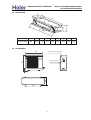
Models
AB122ACERA
AC122ACERA
AD122ALERA
AU122AEERA
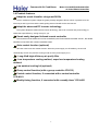
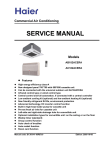
Features
High energy efficiency
Can be connected with the universal outdoor unit AU122AEERA
Infrared control type or wired control type
Low ambient cooling kit (optional) and low ambient heating kit (optional)
New friendly refrigerant R410a, environment protection
Advanced technology, DC inverter control function
Weekly timer (standard)
Group control function
Auto restart function
Room card function
Manual code: SYJS-020-07REV.0
Edition: 2007-05-15
Commercial Air Conditioner
Model: AU122AEERA AB122ACERA
AC122ACERA AD122ALERA
CONTENTS
Contents………………………………………………………...2
1. Description of products & features………………………..3
2. Specification…………………………………………………7
3. Safety precaution…………………………………………..10
4. Net dimension………………………………………………12
5. Installation instructions………..…………………………...14
6. Parts and functions…………………………………………30
7. Controller functions…………………………………………32
8. Refrigerant circuit…………………………………………...33
9. Electrical control functions…………………………………34
10. Electrical data………………………………………………49
11. Troubleshooting …………….....………………………….57
12. Noise level.....................................................................61
2
Commercial Air Conditioner
Model: AU122AEERA AB122ACERA
AC122ACERA AD122ALERA
1.DESCRIPTION OF PRODUCTS & FEATURES
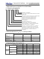
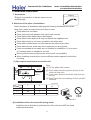
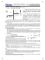
1.1. Products code explanation
A
C 12 2
A C
E R
A
Climate type: T1 (see table 1)
Design number (R stands for design sequence, DC inverter
frequency type)
Product type: A stands for heat pump type, refrigerant is R22
B stands for heat pump type, refrigerant is R407C
E stands for heat pump type, refrigerant is R410a
Q stands for cool only type, refrigerant is R410A
Outlook appearance
Product series: A stands for 1 to 1
Applicable voltage: 2 stands for 220~230V/50Hz,
4 stands for 220V/60Hz,N stand for 380~400VAC/50Hz
Cooling / Heating capacity, 12=12000BTU/h
Product type : “B” stands for cassette type, “C” stands for
convertible type, ”D” stands for duct, “S” stands for wall
mounted type, ”Q” stands for chiller system, "E" stands for
ceiling concealed type, “U” stands for outdoor unit
Air Conditioner
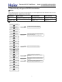
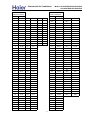
1.2 Brief Introduction for T1、T2、T3 working condition
Climate type
Type
of
Conditioner
Air
T1
T2
T3
Cooling Only
18 ℃~43℃
10℃~35℃
21℃~52℃
Heat pump
-7℃~43℃
-7℃~35℃
-7℃~52℃
Electricity Heating
~43℃
~35℃
~52℃
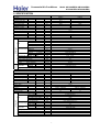
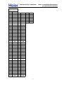
1.3 Operating Range of Air Conditioners
Temp.
Mode
Indoor
Cooling
Outdoor
Indoor
Heating
Outdoor
Rated
Maximum
Minimum
DB
℃
27
32
15
WB
℃
19
23
14
DB
℃
35
43
-5
WB
℃
24
26
6
DB
℃
20
27
10
WB
℃
14.5
---
--
DB
℃
7
23
-10
WB
℃
6
18
---
3
Commercial Air Conditioner
Model: AU122AEERA AB122ACERA
AC122ACERA AD122ALERA
1.4 Product features
Adopt the much friendlier refrigerant R410a
The air conditioner system adopts the greatly friendly refrigerant R410a, which is protective for the
ozone layer and is good to avoid the earth getting warmer. Benefit for the environment.
Adopt the advanced DC inverter technology
The system adopts the advanced DC inverter technology, which can consume less power energy to
realize the equal efficiency, saving money for you.
Smart newly designed infrared remote controller
The cassette and convertible unit can be controlled by the infrared remote controller YR-H71, the remote
controller can be fixed with a remote controller holder.
Auto–restart function (optional)
All indoor units have auto-restart function. When the power supply cut off suddenly, the unit will
automatically recover the previous running mode once the power supply is on.
Long-life& high efficiency air purify filter
Low temperature cooling realized, super low temperature heating
realized.
Low ambient cooling kit (optional)
Group control function (with a group controller YR-E12)
Central control function, if connected with a central controller
YCZ-A001
Weekly timing function, if connected with a weekly timer YCS-A001
4
Commercial Air Conditioner
Model: AU122AEERA AB122ACERA
AC122ACERA AD122ALERA
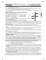
1.5 New friendly refrigerant R410A introduction:
■R410A
The working pressure of R410A is approximately 1.6 times higher than R22. Because the oil in the
refrigerant is different, please do not mix them.
Refrigerant
R22 (single)
R410A (mixed)
R407C (mixed)
Oil
Mineral oil (SONTEX 200LT)
Synthetic oil (POE oil)
Synthetic oil (POE oil)
Pressure ratio
1
Approx. 1.6
Approx. 1.1
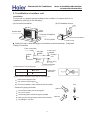
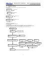
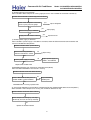
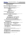
■Operation flow
prepare work schedule
refrigerant inspection
1. Always inspect the used refrigerant
2. Always use the specified refrigerant
operation chart preparation
indoor unit installation
refrigerant piping work
1. Use piping material of the specified thickness
2. Do not use dirty pipe
3. Always flow nitrogen during welding work
drain piping work
duct work
insulation work
remote controller installation
electric wiring work
1. Do not connect the power supply
outdoor unit foundation work
outdoor unit installation
refrigerant piping connection
leakage test
evacuation and drying
additional refrigerant charging
1. Charge the nitrogen to the set pressure
2. 24 hours later,check if the pressure in the pipe
has reduced
1. Air purging by refrigerant is prohibited seriously
2. Use a special vacuum pump with reverse check
mechanism
1. Calculate the refrigerant additional charging
amount, and charge a suitable amount.
gas leakage check
maintenance panel installation
trial running and adjustment
hand over
5
Commercial Air Conditioner
Model: AU122AEERA AB122ACERA
AC122ACERA AD122ALERA
■Piping material
1. Use the correct refrigerant piping and materials for R410A
2. For the pipe wall thickness, see the table below:
Pipe diameter
Φ6.35
Φ9.52
Φ12.7
Φ15.88
Φ19.1
Pipe wall thickness
0.8
0.8
0.8
1.0
1.2
Note: Always observe and comply with the local regulations when installing the refrigerant piping.
■Tools
R410A work requires a number of special tools (* symbol). Since the tools used in R22 work
cannot be used for R410A, provide the tools separately.
Tool name
Process and application
Pipe cutter
Piping cutting
*Flaring tool
Pipe flaring work
*Torque wrench
Flare nut connection
Expander
Expansion at pipe connection
Pipe bender
Pipe bending work
Nitrogen gas
Pipe oxidation prevention
Welder
Pipe brazing
*Gauge manifold
Vacuum
*Charging hose
charging operation check
Refrigerant piping work
evacuation
and
Air tightness test
refrigerant
Air tightness test
Refrigerant
additional
charging
*Vacuum
pump
(with
Vacuum drying
adapter)
Electronic scale
Gas leakage detector
Refrigerant
additional
charging
Gas leakage test
■Work precautions
Refrigerant check: Before work, check the used refrigerant and prepare materials matched to the
refrigerant.
Refrigerant piping: Observe the basics of refrigerant piping to avoid the unnecessary problems. In
addition, when performing the welding work, seal in the nitrogen gas to the pipes, and prevent it
from the oxidation.
Leak pressure detection: Perform seal detection and make sure there is no refrigerant leakage.
Vacuum drying: If the vacuum pump has not the reverse flow check mechanism, use the pump
together with a reverse flow check adapter.
Additional refrigerant: Charge a suitable amount of refrigerant with a special R410A gauge
manifold and charging hose.
6
Commercial Air Conditioner
Model: AU122AEERA AB122ACERA
AC122ACERA AD122ALERA
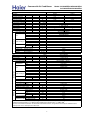
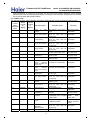
2. SPECIFICATION
Panel
Indoor unit
item
Function
Capacity
Sensible heat ratio
Total power input
Max. power input
EER or COP
ENERGY CLASS
Dehumidifying capacity
Power cable
Power source
Running
Start Current
Circuit breaker
Unit model (color)
Type × Number
Speed(H-M-L)
Fan
Fan motor output power
Air-flow(H-M-L)
Type / Diameter
Heat exchanger Total Area
Temp. scope
External
(L×W×H)
Dimension
Package
(L×W×H)
Drainage pipe (material , I.D./O.D.)
Control type (Remote /wired)
Fresh air hole dimension
Noise level
(H-M-L)
Weight
(Net / Shipping)
External
(L×W×H)
Dimension
Package
(L×W×H)
Weight
(Net / Shipping)
Indoor unit
Item
Function
Capacity
Sensible heat ratio
Total power input
Max. power input
EER or COP
Dehumidifying capacity
Power cable
Power source
Running
Start Current
Circuit breaker
Unit model (color)
Type × Number
Speed(H-M-L)
Fan
Fan motor output power
Air-flow(H-M-L)
Type / Diameter
Heat exchanger Total Area
Temp. scope
External
(L×W×H)
Dimension
Package
(L×W×H)
Drainage pipe (material , I.D./O.D.)
Control type (Remote /wired)
Noise level
(H-M-L)
Weight
(Net / Shipping)
Mode
AB122ACERA
cooling
3.52(0.9--4.4)
0.71
1250(280---1650)
1650
2.81(C)
kW
W
W
W/W
heating
4.4(1.0---4.8)
1210(280--1650)
1650
3.64(A)
1.6
1.5
3×2.5
1, 220--230, 50
6.0(1.4--8.0)A/8A
6.0(1.4--8.0)A/8A
3
3
13
13
AB122ACERA(BLACK)
Centrifugal fan*1
795/690/550±50
0.065
700/620/520
inner grooved pipe/φ7
0.272
2-7
570×570×260mm
718×680×380mm
PVC 26/32
Remote
95
45/40/32
18.5/23
700×700×60mm
740×750×115mm
3.5/4.5
10‐³×m³/h
N, V, Hz
A/A
A
A
r/min
kW
m³/h
mm
m²
℃
mm×mm×mm
mm×mm×mm
mm
mm
dB(A)
kg / kg
mm×mm×mm
mm×mm×mm
kg / kg
Model
AC122ACERA
cooling
4.1(0.9--4.6)
0.71
1270(280---1650)
1650
3.23(A)
kW
W
W
W/W
10‐³×m³/h
heating
4.4(1.0---5.1)
1210(280--1650)
1650
3.64(A)
1.6
3×2.5
1, 220--230, 50
6.0(1.4--8.0)A/8A
6.0(1.4--8.0)A/8A
3
3
13
13
AC122ACERA(WHITE)
Centrifugal fan*2
1200/1080/880
0.09
750/650/550
inner grooved pipe/φ7
0.20
2-7
1090×655×199
1150×750×300
PVC 18/20
Remote
46/44/42
28.3/34.3
N, V, Hz
A/A
A
A
r/min
kW
m³/h
mm
m²
℃
mm×mm×mm
mm×mm×mm
mm
dB(A)
kg / kg
7
Commercial Air Conditioner
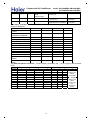
Indoor unit
Item
Function
Capacity
Sensible heat ratio
Total power input
Max. power input
EER or COP
Dehumidifying capacity
Power cable
Power source
Running
Start Current
Circuit breaker
Unit model (color)
Type × Number
Speed(H-M-L)
Fan
Fan motor output power
Air-flow(H-M-L)
Type / Diameter
Heat exchanger Total Area
Temp. scope
External
(L×W×H)
Dimension
Package
(L×W×H)
Drainage pipe (material , I.D./O.D.)
Control type (Remote /wired)
Noise level
(H-M-L)
Weight
(Net / Shipping)
Model: AU122AEERA AB122ACERA
AC122ACERA AD122ALERA
Model
AD122ALERA
cooling
3.8(0.9--4.4)
0.71
1260(280--1650)
1650
3.02(B)
kW
W
W
W/W
10‐³×m³/h
heating
4.1(1.0---4.8)
1260(280--1650)
1650
3.25(C)
1.6
3×2.5
1, 220--230, 50
6.0(1.4--8.0)A/8A
6.0(1.4--8.0)A/8A
3
3
13
13
AD122ALERA(GREY)
Centrifugal fan*1
1000/900/800±50
0.05
550/450/400
inner grooved pipe/φ7
0.11
2-7
610×483×220
695×536×265
20/18
wired
35/32/30
14/16
N, V, Hz
A/A
A
A
r/min
kW
m³/h
mm
m²
℃
mm×mm×mm
mm×mm×mm
mm
dB(A)
kg / kg
PIPING
Outdoor unit
Item
Mode
AU122AEERA
3×2.5
Power cable
1, 220-230, 50
Power source
N, V, Hz
3
Start Current
A
Unit model (color)
AU122AEERA(WHITE)
C-6RZ092H1A
Model / Manufacture
Compressor
twin rotary
Type
axial*1
Type × Number
840r/min±50
Speed
r/min
Fan
0.06
Fan motor output power
kW
2500/-/Air-flow(H-M-L)
m³/h
Type / Diameter
mm
TP2M/Φ9.52
Heat exchanger Total area
0.374
m²
43-60
Temp. scope
℃
775x640x245
External
(L×W×H) mm×mm×mm
Dimension
901x341x712
Package
(L×W×H) mm×mm×mm
Refrigerant control method
mm/mm Capillary tube: main φ3×φ1.8×920,assistant φ3×φ1.8×780
Defrosting
auto
55
Noise level
dB(A)
Type of Four way valve
SHF-4-10A
XPE
material of reduce noise
37
crankcase heater power
W
Weight(Net / Shipping)
39/43
kg / kg
R410A 1300
Type / Charge
g
Refrigerant
30
Recharge quantity
g/m
6.35
Liquid
mm
Pipe
12.7
Gas
mm
flared
Connecting Method
MAX.Drop
10
m
Between I.D &O.
MAX.Piping length
20
m
Norminal condition: indoor temperature (cooling): 27 ℃DB/19℃WB, indoor temperature (heating): 20 ℃DB/14.5℃WB
Outdoor temperature(cooling): 35℃DB/24℃WB, outdoor temperature(heating): 7 ℃DB/6℃WB
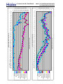
The noise level will be measured in the third octave band limited values, using a Real Time Analyser calibrated sound
intensity meter. It is a sound pressure noise level.
8
Commercial Air Conditioner
Model: AU122AEERA AB122ACERA
AC122ACERA AD122ALERA
Norminal condition: indoor temperature (cooling): 27℃DB/19℃WB, indoor temperature (heating): 20℃DB
Outdoor temperature(cooling): 35℃DB/24℃WB, outdoor temperature(heating): 7℃DB/6℃WB
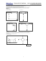
The noise level will be measured in the third octave band limited values, using a Real Time Analyser calibrated sound intensity meter.
It is a sound pressure noise level. The detailed method please refer to the following information:
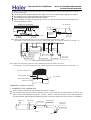
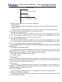
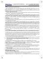
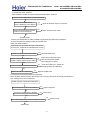
Installation state: the unit should be placed on the flat floor or be mounted in horizontal
direction.
Testing method:
built-in-ceiling unit:
mounting-on-ceiling unit:
1m
1.4m
1m
duct unit without auxiliary duct:
duct unit with auxiliary duct:
2m
duct
2m
1m
auxiliary duct
auxiliary duct
1.4m
1.4m
1m
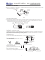
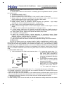
outdoor unit:
1.air outlet from side: the noise level is the average sound pressure level measured from front, left, right directions.
2.air outlet from top: the noise level is the average sound pressure level measured from front, back, left, right directions.
measured point:
H ( height to the ground) = (h (unit height) + 1m) /2
and, it is 1m to each side.
1m
1m
1m
h
Note: ⊙ is the real
time analyser
9
Commercial Air Conditioner
Model: AU122AEERA AB122ACERA
AC122ACERA AD122ALERA
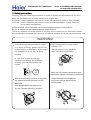
3. Safety precaution
Carefully read the following information in order to operate the airconditioner correctly.
Below are listed three kinds of Safety Cautions and Suggestions.
WARNING! Incorrect operations may result in severe consequences of death or serious injuries.
CAUTION! Incorrect operations may result in injuries or machine damages; in some cases may
cause serious consequences.
INSTRUCTIONS: These information can ensure the correct operation of the machine.
Be sure to conform with the following important Safety Cautions.
The Safety Cautions should be at hand so that they can be checked at any time when needed.
If the conditioner is transferred to the new user, this manual should be as well transferred to the new user.
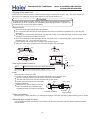
WARNING!
If any abnormal phenomena is found
(e. g.smell of firing), please cut off the
power supply immediately, and contact
the dealer to find out the handling
method.
Don't dismantle the outlet of the
outdoor unit.
The exposed fan is very dangerous
which may harm human beings.
In such case, to continue using the
conditioner will damage the conditioner,
and may cause electrical shock or fire
hazard.
switch
off
When the unit needs maintenance and
repairment, please call dealer to handle it.
After the unit being used for a long time,
the base should be checked for any
damages.
If the damaged base is not repaired, the
unit may fall down and cause accidents.
1000
Incorrect maintenance and repairment
may cause water leak, electrical shock
and fire hazard.
Commercial Air Conditioner
Model: AU122AEERA AB122ACERA
AC122ACERA AD122ALERA
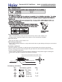
WARNING!
Installed electrical-leaking circuit
breaker.
Nothing or nobody is permitted to
placed on or stand on outdoor unit.
It easily cause electrical shock without
circuit breaker.
The falling of goods and people may
cause accidents.
Air-conditioner can't be installed in
the environment with inflammable
gases because the inflammable gases
near to air-conditioner may cause fire
hazard.
Please let the dealer be responsible for
installing the conditioner.
Don't operate the air-conditioner with
damp hands.
Incorrect installation may cause water
leak, electrical shock and fire hazard.
Otherwise will be shocked.
Call the dealer to take measures to
prevent the refrigerant from leaking.
If conditioner is installed in a small
room be sure to take every measure in
order to prevent suffocation accident
Only use correctly-typed fuse.
even in case of refrigerant leakage.
May not use wire or any other materials
replacing fuse, other-wise may cause
faults or fire accidents.
When conditioner is removed or
reinstalled, dealer should be
responsible for them.
Incorrect installation may cause water
leaking, electrical shock and fire hazard.
Connect earthing wire.
Earthing wire should not be connected to the gas pipe, water pipe,
lightning rod or phone line, in-correct
earthing may cause shock.
Use discharge pipe correctly to ensure
efficient discharge.
Incorrect pipe use may cause water
leaking.
Earthing
11
Commercial Air Conditioner
Model: AU122AEERA AB122ACERA
AC122ACERA AD122ALERA
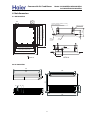
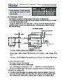
4. Net dimension
4.1 AB122ACERA
:;9
A9
U\MXRIVML LQYZITKM JMZ]MMT ZPM KMQRQTO
ITL ZPM VITMRC ;>SS
VITMR
KMQRQTO
B>
:A9
><>SS 7JMZ]MMT Y[YVMTYQUT VURMY8
NXMYP IQX PURM
>@9SS 7QTLUUX [TQZ LQSMTYQUT8
?>9SS 7KMQRQTO UVMTQTO LQSMTYQUT8
@99SS 7VITMR LQSMTYQUT8
:=9
GFEH D
GFEH D
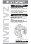
4.2 AC122ACERA
620
605
600
880
100
655
40
35
35
30
990
12
240
200
199
900
<;9SS
Y[YVMTYQUT PURLMX
:>9SS
@99SS 7VITMR LQSMTYQUT8
OIY VQVM
?>9SS 7KMQRQTO UVMTQTO LQSMTYQUT8
RQW[QL VQVM
>@9SS 7QTLUUX [TQZ LQSMTYQUT8
LXIQTIOM VQVM
?9SS
B9
Commercial Air Conditioner
Model: AU122AEERA AB122ACERA
AC122ACERA AD122ALERA
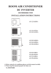
4.3 AD122ALERA
;
>
?
:
A
@
B
= <
9EBG DF=>C
:
45-..47684
1/3
;
03/+1
<
=
>
?
@
A
B
-/-
2-,
.11
-,1
0-3
1,3
..,
4.4 AU122AEERA
23+
6AF;B 8=B=@< 7;B?=@9>
245
-0
1/+
6AF;B 8=B=@<
4=CDB=:ED=A@ 5A>;
0++
13
Commercial Air Conditioner
Model: AU122AEERA AB122ACERA
AC122ACERA AD122ALERA
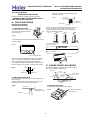
5. Installation Instructions
1. Accessories
Edging
"Edging" for protection of electric wires from an
opening edge.
2. Selection of the place of installation
Select the place of installation satisfying the following conditions and, at the
same time, obtain a consent from the client or user.
Place where air circulates.
Place free from heat radiation from other heat sources.
Place where drain water may be discharged.
Place where noise and hot air may not disturb the neighborhood.
Place where there is not heavy snowfall in the winter time.
Place where obstacles do not exist near the air inlet and air outlet .
Place where the air outlet may not be exposed to a strong wind.
Place surrounded at four sides are not suitable for installation. A 1m or more
of overhead space is needed for the unit.
Mount guide-louvers to place where short-circuit is a possibility.
When installing several units, secure sufficient suction space to avoid short
circuiting.
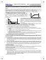
(1) Open space requirement around the unit
L2
Air
inlet
L3
Air inlet
500
(Servicing
space)
Air outlet
L1
Note :
(1) Fix the parts with screws
(2) Don't intake the strong wind directly to the
outlet air-flow hole.
(3) A one meter distance should be kept from the
unit top
(4) Don't block the surroundings of the unit with
sundries
Unit: mm
Case
Distance
I
L1
II
III
open
open
500
L2
300
0
open
L3
150
300
150
NO
Wind direction
(2) Installation where the area with strong winds.
Install the unit so that the air outlet section of the unit must NOT be faced
toward wind direction.
14
Commercial Air Conditioner
Model: AU122AEERA AB122ACERA
AC122ACERA AD122ALERA
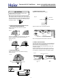
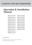
5.1 Installation of outdoor unit
Installation
Fix the unit in a proper way according to the condition of a place where it is
installed by referring to the following .
(a) Concrete foundation
(b) Foundation anchor
Unit
Unit
Anchor bolt
Concrete foundation
Concrete foundation
To fix by bolts
Anchor bolt
Install the unit so that the angle of inclination must be less than 3 degrees.
~9@9>7 r?>>53D9?>
u<1B5 3?>>53D9?>
f`G1I F1<F5
v1C @9@5
x>4??B
->9D
}ED4??B
E>9D
z9AE94
@9@5
e`G1I F1<F5
u<1B5 3?>>53D9?>
]d^ s9=5>C9?> ?6 3?>>53D9>7 @9@5
v1C @9@5
deaj==
z9AE94 @9@5
iafh==
u9D D85 >ED ?>
1>4 61CD5>
90 + 0.5
]e^ ,85 =1H9=E= <5>7D8 1>4 4B?@ 85978D ?6 3?>>53D9>7 @9@5
,85 =1H9=E= <5>7D8 9C ec=
,85 =1H9=E= 4B?@ 85978D 9C 15m
,? 5>CEB5 D85 5669395>3I _~9@5C C81<< 25 1C C8?BD 1C @?CC92<5a
r1ED9?>C 6?B @9@9>7 3?>>53D9?>
y?9>D
+@1>>5B
s? >?D DG9CD ?B 456?B= D85 3?>>53D9>7 @9@5a
s? >?D =9H 4ECDCa
,85 25>49>7 B149EC C81<< 25 1C <1B75 1C @?CC92<5a
q?D8 71C @9@5 1>4 <9AE94 @9@5 C81<< 25 851D 9>CE<1D9?>a
|? <51;175 9> D85 6<1B5a
15
+@1>>5B
|ED
Commercial Air Conditioner
2
¡
16
Model: AU122AEERA AB122ACERA
AC122ACERA AD122ALERA
Commercial Air Conditioner
Model: AU122AEERA AB122ACERA
AC122ACERA AD122ALERA
Electric wiring
WARNING!
DANGER OF BODILY INJURY OR DEATH
TURN OFF ELECTRIC POWER AT CIRCUIT BREAKER OR POWER
SOURCE BEFORE MAKING ANY ELECTRIC CONNECTIONS.
GROUND CONNECTIONS MUST BE COMPLETED BEFORE MAKING
LINE VOLTAGE CONNECTIONS.
(1) Selection of size of power supply and interconnecting wires.
Precautions for Electric wiring
Electric wiring work should be conducted only by authorized personnel.
Do not connect more than three wires to the terminal block. Always use round
type crimped terminal lugs with insulated grip on the ends of the wires.
Use copper conductor only.
Select wire sizes and circuit protection from table below. (This table shows 20 m
length wires with less than 2% voltage drop.)
Circuit breaker
Item
Model
AU122AEERA
PhaseSwitch breaker
(A)
1
Overcurrent
protector
40
Power
source wire
size
2.5 mm2
26
Earth leakage breaker
Switch
break
Leak
curren
40A
30mA
(2) Wiring connection
Make wiring to supply power to the outdoor unit, so that the power for the indoor
unit is supplied by terminals.
For the detailed wiring connection with the indoor units, see the corresponding
indoor operation and instruction manual.
To Indoor Unit
OUTDOOR UNIT
TERMINAL BLOCK
1 2 3
Y/G
WARNING!
INTERCONNECTING WIRES MUST BE WIRED ACCORDING TO FIG.1
INCORRECT WIRING MAY CAUSE EQUIPMENT DAMAGE.
17
Commercial Air Conditioner
t
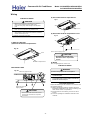
5.2 Indoor unit ins allation
5.2.1 AB122ACERA
Jhmn[ff[ncih niifm
Tb_ chmn[ff[ncih niifm fcmn_^ ch nb_
`iffiqcha mb__n ][h \_ om_^ [m l_kocl_^2
52 S]l_q ^lcp_l
62 I[]em[q
72 Elcff qcnb [ ^c[g_n_l i` :4gg
82 Jhh_l b_r[aih mj[hh_l0mbc`ncha
mj[hh_l
92 Sj[hh_l -580 5;0 5=06806;gg.
:2 Pcj_ ]onn_l
;2 Pcj_ _rj[h^_l
<2 Khc`_
=2 Pch]_lm
Model: AU122AEERA AB122ACERA
AC122ACERA AD122ALERA
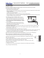
52S_f_]ncih i` Jhmn[ff[ncih Pf[]_
-5. Pf[]_ [\ip_ nb_ ]_cfcha qb_l_ b[p_ _hioab mj[]_ ni [ll[ha_
nb_ ohcn2
-6. Pf[]_ qb_l_ nb_ ^l[ch[a_ jcj_ ][h \_ [ll[ha_^ q_ff2
-7. Pf[]_ qb_l_ chf_n [h^ ionf_n [cl i` ch^iil [h^ ion^iil ohcn qcff hin
\_ \fi]e_^2
-8. Ei hin _rjim_ nb_ ohcn ni nb_ jf[]_ qcnb b_[ps icf il gicmnol_
-_2a2ecn]b_h [h^ qilembij.2
-9. Ei hin m_n nb_ ohcn ch nb_ jf[]_ qb_l_ ^_mnlo]ncp_ a[m -mo]b [m
mof`olc] []c^ a[m. il joha_hn a[m -nbchh_l [h^ a[mifch_. ]ih]_hnl[n_m
[h^ l_n[chm2
-:. Pf[]_ mnliha _hioab ni mojjiln nb_ ohcn q_cabn2
-;. Ni _rj_hmcp_ [lnc]f_m mo]b [m n_f_pcmcih [h^ jc[hi \_fiq
ch^iil ohcn2
-<. Fhioab mj[]_ `il g[chn_h[h]_2
-=. Pf[]_ gil_ nb[h 5g [q[s `lig n_f_pcmcih [h^ l[^ci ni [pic^
^cmnol\cha n_f_pcmcih [h^ l[^ci2
-54. F[ms `il g[chn_h[h]_2
H
552 C[h^ n[j_
562 S]l[j_l
0.31m
542 L_[e[a_ ^_n_]nil il mi[js q[n_l
572 R_`lca_l[hn icf
Sn[h^[l^ []]_mmilc_m
6
R_gin_ ]ihnliff_l
C[nn_ls
Qns2
5
Air outlet
1.5m
1.5m
2.5m Over
62Jhmn[ff[ncih Pl_j[l[ncih
-5. Pimcncih i` ]_cfcha ij_hcha \_nq__h ohcn [h^ momj_h^cha \ifn
-`lihn pc_q i` ohcn.2
6
7
Wcl_ ]f[gj
8
8
I_[n
jl_m_lp[ncih
mf__p_
5/5
9
S]l_q
6/8
Indoor unit 570mm
5
B]]_mmils j[lnm
Air inlet
Ceiling opening 650mm
Ni2
Air outlet
Ornament panel 700mm
Tb_ `iffiqcha j[lnm g_hncih_^ ch nbcm
g[ho[f [l_ nb_ chmn[ff[ncih []]_mmilc_m
q_ jl_j[l_^2
Distance between
suspending bolts 535mm
Indoor unit 570mm
Ceiling opening 650mm
5
Ornament panel 700mm
Overlap between ceiling and
ornament panel shall be 25mm
Suspending bolts
150mm
R_gin_
]ihnliff_l
\l[]e_n
5/5
Ceiling
Ornament panel
320mm
;
S]l_q ][j
60mm
:
-6. Pl_j[l_ [ff jcjcha -l_`lca_l[hn0q[n_l ^l[ch[a_ .[h^ qcl_m
-]ihh_]ncih qcl_ i` l_gin_ ]ihnliff_l0 ch^iil ohcn ]ihh_]ncih qcl_m.
ni nb_ ch^iil ohcn \_`il_ chmn[ff[ncih ch il^_l ni ]ihh_]n ch^iil ohcn
cgg_^c[n_fs [`n_l chmn[ff[ncih2
Commercial Air Conditioner
Model: AU122AEERA AB122ACERA
AC122ACERA AD122ALERA
-7. Jhmn[ff [ momj_h^cha \ifn
Ti mojjiln nb_ ohcn q_cabn 0[h]bil \ifn mbiof^ \_ om_^ ch nb_ ][m_ i` [fl_[^s _rcmnm ]_cfcha2 Giq h_q ]_cfcha0
om_ `fomb1ch nsj_ \ifn0 \ocfn1ch nsj_ \ifn il j[lnm jl_n[l_^ ch nb_ `c_f^2
C_`il_ aicha ih chmn[ffcha0 [^domn mj[]_ ni ]_cfcha2
Rii`
Bh]bil \ifn
Liha hon il nbl_[^
Somj_h^cha \cfn M54
D_cfcha
Nin_> Bff nb_ [\ip_ g_hncih_^ j[lnm mb[ff \_ jl_j[l_^ ch `_cf^0
nb_ ^c[g_n_l i` momj_h^cha \ifn cm M54
72 Jhmn[ff[ncih i` ch^iil ohcn
@Jhmn[ff[ncih Fr[gjf_A
Jh ][m_ i` hi ]_cfcha
Jhmn[ff ohcn n_gjil[lcfs
Pon momj_h^cha \l[]e_n ih nb_ momj_h^cha \ifn ni b[ha nb_ ohcn oj2 C_ mol_ ni om_ hon [h^ q[mb_l [n \inb _h^
i` nb_ \l_[e_n ni m_]ol_ `clgfs2
B`n_l chmn[ff[ncih ih nb_ ]_cfcha
-5. B^domn ohcn ni cnm lcabn jimcncih -R_`_l ni jl_j[l[ncih `il chmn[ff[ncih1-5..
-6.Db_]e nb[n ohcn cm biltihn[f2
W[n_l jogj [h^ `fi[ncha mqcn]b cm chmn[ff_^ chmc^_ ch^iil ohcn0]b_]e `iol ]ilh_lm i` nb_ ohcn `il cnm f_p_l omcha
bilctihn[f ]igj[l[nil il PVD no\_ qcnb q[n_l2-J` ohcn cm ncfncha [a[chmn nb_ ^cl_]ncih i` q[n_l ^l[ch[a_0jli\f_g
g[s i]]ol ih `fi[ncha q[n_l f_[e[a_2.
Jh nb_ ][m_ i` ]_cfcha [fl_[^s _rcmnm
-5.Jhmn[ff ohcn n_gjil[ffs
Pon momj_h^cha \l[]e_n ih nb_ momj_h^cha \ifn ni b[ha nb_
ohcn oj2C_ mol_ ni om_ hon [h^ q[mb_l [n \inb _h^ i` nb_
\l[]e_n ni m_]ol_ cn `clgfs2
-6.B^domn nb_ b_cabn [h^ jimcncih i` nb_ ohcn2
-7.Pli]__^ qcnb jli]_^ol_ -8. i` + Jh nb_ ][m_ i` hi ]_cfcha +
Non -Pl_j[l_ ch `_cf^.
W[mb_l -Pl_j[l_^ ch `_cf^.
Somj_h^cha \ifnm
G[mn_h -^io\f_ honm.
Jhm_ln
f_p_f_l
W[mb_l `crcha j[^
-jl_j[l_^ ch `_cf^.
X m_]ol_ nb_ q[mb_l `clgfsY
Pifsnb_h_ jcj_
4. Installation of water drainage pipe
(1) Install water drainage pipe
Pipe diameter shall be equal or larger than that of connecting pipe (Pipe of polythene; size: 25mm;
O.D.: 32mm )
Drainpipe should be short, with a downward slope at least 1/100 to prevent air bag from forming.
If downward slope of drainpipe cannot be made,lifting pipe shall be installed.
Keep a distance of 1-1.5m between suspending bolts, to make water hose straight.
19
Commercial Air Conditioner
Model: AU122AEERA AB122ACERA
AC122ACERA AD122ALERA
1-1.5m
slope over 1/100
Use the drainage hose and clip provided with unit.
Insert water pipe into water plug until it reaches the white tape.
Tighten the clip until head of the screw is less than 4mm from hose.
Wind the drainage hose to the clip using seal pad for heat insulation.
Insulate drainage hose in the room.
Large size seal pad
(accessory)
Clip
Tape(white)
Clip
Draingage hose
4mm below
5. Cautions for the water drainage lifting pipe
Installation height of water drainage lifting pipe shall be less than 280mm
Clip
220mm
500mm below
220
Water drainage
lifting pipe
Drainage hose
500mm below
300mm below 1-1.5m Suspending bracket
280mm unter
Drainage hose
75mm below
There should be a right angle with unit ,300mm from unit.
< Note >
The slope of water drainage hose shall be within 75mm , make the drainage plug not to bear
excessive force.
100mm ¸over
If several water hoses join together, of as per following procedures.
Slope below 1/100
Connection drainage hose with a T-joint
Specifications of the selected drainage hoses shall meet the requirements for the unit running
6. Installation of Ornament Panel
Install ornament panel on indoor unit
(1) Check whether indoor unit is horizontal with leveler or polythene pipe filled with water , and
check that the dimension of the ceiling opening is correct. Take off the lever gauge before
installing the ornament panel.
(2) Fasten the screws to make the height difference between the two sides of indoor unit less than
5mm.
(3) Firstly fix it with screws temporarily.
(4) Fasten the two temporarily fixing screws and other two, and tighten the four screws.
(5) Connect the wires of synchro-motor.
(6) Connect the wire of signal.
(7) If no response of remote controller,check whether the wiring is correct,restart remote controller
10 seconds after shut off power supply.
20
Commercial Air Conditioner
Model: AU122AEERA AB122ACERA
AC122ACERA AD122ALERA
Electric control box
Panel limitation board installation
(1)Install the panel board in the direction shown in the figure.
(2)The incorrect direction will result in water leakage,meanwhile swing and signal receiving are displayed
that cannot be connected.
21
Commercial Air Conditioner
Model: AU122AEERA AB122ACERA
AC122ACERA AD122ALERA
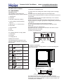
5.2.2 AC122ACERA
Wrap the insulation around the drain hose
connection.(Fig.6)
INSTALLATION PROCEDURE
Install the room air conditioning unit as follows:
(Fig. 6)
PREPARING INDOOR UNIT INSTALLATION
Drain pan
FIRST REMOVE THE INTAKE GRILL
A. FLOOR MOUNTING
Insulation
(Drain hose)
Drain hose
(AC36/42 only suitable for
exposed ceiling mounting)
1. DRILLING FOR PIPING
The piping and drain can exit the
unit in two directions as shown
below in (Fig. 2)
rear
Be sure to arrange the drain hose correctly as shown
in Fig. 7 so that it is lower than the drain hose
connecting point of the indoor unit, if condensate
pump is not fitted to system.
Fig. 7
OK
NO
NO
(Fig. 2)
down
The drain hose must be connected to the right side as
shown in (Fig.3).
Arrange the drain hose
lower than this portion.
(Fig. 3)
Drain hose
CAUTION!
Ensure that the unit is fixed level. Height ‘A’ must be less
than 5 mm.(Fig.8)
Drain hose (Right side)
After the piping and drainage exit has been selected,
drill a 7 cm dia. hole through the wall so that the
hole is slanting downward toward the outside to
ensure good drainage. When the pipe is led out from
the rear, make a hole as Fig.4, at the position shown.
(Fig. 4)
Wall
6mm
Drain hose
A
B. UNDER CEILING MOUNTING
Using the installation template, drill holes for piping
and anchor bolts(for holes).(Fig.9)
7cm
Indoor unit
(Fig. 10)
200mm
2. INSTALLING DRAIN HOSE
The drain hose must be connected to the right side of
the unit (Fig.3)
Insert the drain hose into the drain pan, then secure
the drain hose with a nylon fastener. (Fig.5)
(Fig. 5)
900mm
outdoor unit
Installation
template
Drilling position
for anchor bolt
Ceilling
Wall
Drilling position
for piping
1. DRILLING FOR PIPING
Select piping and drain directions. (Fig.10)
Drain pan
Nylon fastener
(supplied by others)
Fig 10
Drain hose
22
Rear (Install the drain hose
in this direction.)
Commercial Air Conditioner
Model: AU122AEERA AB122ACERA
AC122ACERA AD122ALERA
4. INSTALLING INDOOR UNIT
Reset the hex bolts as shown in Fig.14.
CAUTION
Install the drain hose at the rear; it should not be
installed on the top or right side.
After the piping and drainage exit has been selected,
drill 80mm and 50mm or 150mm dia. hole through the
wall. So that the hole is slanting downward toward the
outside for smooth water flow if a condensate pump is
not fitted to system. Wall
Fig. 14
Hex bolt
8 to 13mm
Indoor unit
6mm
2. DRILLING HOLES FOR ANCHOR BOLTS AND
INSTALLING THE ANCHOR BOLTS
using a masonry drill, drill four 12.5 mm dia.
Holes.(Fig.11)
Apply the indoor unit to the brackets.(Fig.15)
Fig. 15
Fig. 11
Fig. 11
Bracket
Bolt
Indoor unit
12.5mm
Insert the anchor bolts into the drilled holes, and drive
the pins completely into the anchor bolts with a
hammer. (Fig. 12)
Now, securely tighten the hex bolts in both sides.
Fig. 12
5. INSTALL THE DRAIN HOSE
The drain hose will be connected to the right side.(Fig.3)
Insert the drain hose into the drain pan, then secure the
drain hose with a nylon fastener.(Fig.5)
Wrap the insulation (drain hose)around the drain hose
connection. (Fig.9)
Be sure to arrange the drain hose correctly so that it is
lower than the drain hose connecting port of the indoor
unit (Fig.16) if condensate pump is not fitted to system.
3. INSTALLING BRACKETS
Install the brackets with nuts, washers and spring
washers.(Fig. 13)
Fig. 16
Remove the hole cover.
Fig. 13
Arrange the drain hose
lower than this portion
Spring washer
OK
Bracket
Special nut
381
26.5
16 21 28
5
4-R
7.5
68
18
10
2-R2.5
232
232
26.5
10
18
26.5
7.5
2-R2.5
5
4-R
26.5
28 21 16
68
381
23
Drain hose
NO
Commercial Air Conditioner
Model: AU122AEERA AB122ACERA
AC122ACERA AD122ALERA
Wiring
(2) Pull out the electrical component box.
ELECTRICAL WIRING
Fig. 27
CAUTION
(1) Match the terminal block numbers and connection
cable colours with those of the outdoor unit.
Incorrect wiring may cause damage to the electrical
parts.
(2) Connect the connection cables firmly to the terminal
block. Incorrect installation may result in a fire.
Electrical component box
(3) Always fasten the outside covering of the connection
cable with the cable clamp.(If the insulation is chafed,
a short curcuit may occur.)
(3) Remove the electrical component box cover.
Fig. 28
(4) Always connect the earth wire.
1. INDOOR UNIT SIDE
(1) Remove the electrical component box.
Base
Fig. 25
Electrical component box cover
Remove the three tapping screws
CAUTION
Be careful not to pinch the wiring
between the electric component box
and base.
Electrical component box
(4) Wiring
See wiring diagrams for indoor unit.
ELECTRICAL WIRING
INDOOR UNIT SIDE
Fig. 26
WARNING
Electrical component box
(1) Ensure all wiring complies with current regulations.
(2) It is recommended that a MCB of the correct rating is used
to protect the system.
(3) Always use a circuit breaker that can trip all the poles of the
wiring is fitted and has an isolation distance of at least 3mm
between the contacts of each pole.
CUSTOMER GUIDANCE
Explain the following to the customer in accordance with
the operating manual:
(1) Starting and stopping method, operation switching,
temperature adjustment, timer, air flow switching, and
other remote control unit operations.
(2) Air filter removal and cleaning, and how to use air
louvres.
(3) Give the operating and installation manuals to the
customer.
Remove the four self
tapping screws.
CAUTION
Do not remove the screws. If the screws
are removed, the electrical component
box will fall.
24
Commercial Air Conditioner
Model: AU122AEERA AB122ACERA
AC122ACERA AD122ALERA
5.2.4 AD122ALERA
GbghU``Uh]cb gdUWY
Q\Y ]bXccf ib]h g\U`` VY ]bghU``YX Uh `cWUh]cbg k\YfY Wc`X UbX \ch U]f Wci`X YjYb`m W]fWi`UhYX2
Q\Y Zc``ck]b[ `cWUh]cbg g\ci`X VY Ujc]XYX>
M`UWYg k]h\ f]W\ gU`h -gYUg]XY UfYU.2
M`UWYg k]h\ d`Ybhm cZ [Ug gi`Z]XYg -aU]b`m ]b kUfa gdf]b[ UfYUg k\YfY h\Y WcddYf hiVY UbX VfUnY kY`X
]g YUgm hc Wcffcg]cb.2
IcWUh]cbg k]h\ aiW\ c]` -]bW`iX]b[ aYW\Ub]WU` c]`. UbX ghYUa2
IcWUh]cbg ig]b[ cf[Ub]W gc`jYbhg2
M`UWYg k\YfY h\YfY UfY aUW\]bYg [YbYfUh]b[ FD Y`YWhfcaU[bYh]W kUjYg2
Mcg]h]cbg UX^UWYbh hc Xccf cf k]bXck ]b WcbhUWh k]h\ \][\1\ia]X]hm YlhYfbU` U]f2 -CUgm hc [YbYfUhY XYk.2
IcWUh]cbg ZfYeiYbh`m ig]b[ gdYW]U` UYfcgc`g2
Q\Y Zc``ck]b[ dc]bhg g\ci`X VY hU_Yb WUfY cZ>
52 PY`YWh gi]hUV`Y d`UWYg h\Y cih`Yh U]f WUb VY gYbh hc h\Y
Ybh]fY fcca0 UbX WcbjYb]Ybh hc `Um cih h\Y WcbbYWh]cb
d]dY0 WcbbYWh]cb k]fY UbX h\Y XfU]bU[Y d]dY hc cihXccf2
62 Q\Y WY]`]b[ ghfiWhifY aigh VY ghfcb[ Ybci[\ hc giddcfh
h\Y ib]h kY][\h2
72 Q\Y WcbbYWh]b[ d]dY0 XfU]b d]dY UbX WcbbYWh]cb k]fY
w*~ t
g\U`` VY UV`Y hc [c h\ci[\ h\Y Vi]`X]b[ kU`` hc WcbbYWh
VYhkYYb h\Y ]bXccf UbX cihXccf ib]hg2
82 Q\Y WcbbYWh]b[ d]dY VYhkYYb h\Y ]bXccf UbX cihXccf ib]hg Ug kY`` Ug h\Y XfU]b d]dY g\U`` VY Ug g\cfh
Ug dcgg]V`Y2 -PYY D][ifY 5.
92 GZ ]hg bYWYggUfm hc UX^igh h\Y Z]``]b[ Uacibh cZ h\Y fYZf][YfUbh0 d`YUgY fYZYf hc h\Y ]bghU``Uh]cb aUbiU`
UhhUW\YX k]h\ h\Y cihXccf ib]h2
:2 Q\Y WcbbYWh]b[ Z`Ub[Y g\ci`X VY dfcj]XYX Vm h\Y igYf \]agY`Z2
;2 Q\Y ]bXccf ib]h \Ug hkc kUhYf cih`Yhg cbY cZ k\]W\ ]g cVghfiWhYX Uh h\Y ZUWhcfm -k]h\ U fiVVYf WUd.2 Lb`m
h\Y cih`Yh bch cVghfiWhYX -`]ei]X ]b`Yh UbX cih`Yh g]XY. k]`` VY [YbYfU``m igYX Xif]b[ ]bghU``Uh]cb2 GZ
Udd`]WUV`Y0 Vch\ h\Y cih`Yhg g\ci`X VY igYX hc[Yh\Yf2
KchY> Q\Y UWWYgg \c`Y aigh VY dfcj]XYX Xif]b[ ]bghU``Uh]cb cZ ]bXccf ib]h Zcf aU]bhYbUbWY2
8?K>I J>C><KBE@ KA> BEJK;CC;KBFE JG;<>6| GIF<>>= KA> ?FCCFMBE@ JK>GJ7
74 Djadd Y `gd] af l`] oYdd Yf\ afk]jl l`] [gff][laf_ hah] Yf\ oaj] l`jgm_` Y PVC oYdd3
l`jgm_` lmZ] hmj[`Yk]\ dg[Yddq4 T`] oYdd `gd] k`Ydd Z] oal` Y gmloYj\ \gof kdgh] g^ Yl
d]Ykl 757664 /S]] Fa_mj] 80
84 B]^gj] \jaddaf_ [`][c l`Yl l`]j] ak fg hah] gj j]af^gj[af_ ZYj bmkl Z]`af\ l`] \jaddaf_
hgkalagf4 Djaddaf_ k`Ydd Ynga\ Yl hgkalagfk oal` ]d][lja[ oaj] gj hah]4
94 Mgmfl l`] mfal gf Y kljgf_ Yf\ `gjargflYd Zmad\af_ jgg^4 I^ l`] ZYk] ak fgl ^aje2 al oadd
[Ymk] fgak]2 naZjYlagf gj d]YcY_]4
:4 Smhhgjl l`] mfal ^ajedq4
;4 C`Yf_] l`] ^gje g^ l`] [gff][lagf hah]2 [gff][lagf oaj] Yf\ \jYaf hah] kg l`Yl l`]q
[Yf _g l`jgm_` l`] oYdd `gd] ]Ykadq4
25
Fa_ 8
Commercial Air Conditioner
Model: AU122AEERA AB122ACERA
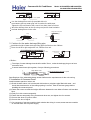
AC122ACERA AD122ALERA
CUW\ cZ h\Y U]f gYbX]b[ XiWh UbX U]f fYhifb XiWh g\U`` VY Z]lYX cb h\Y dfYZUVf]WUhYX dUbY` cZ h\Y Z`ccf
Vm h\Y ]fcb VfUW_Yh2
Q\Y fYWcaaYbXYX X]ghUbWY VYhkYYb h\Y YX[Y cZ h\Y U]f fYhifb XiWh UbX h\Y kU`` ]g cjYf 594aa2
Q\Y [fUX]Ybh cZ h\Y WcbXYbgUhY kUhYf d]dY g\U`` _YYd cjYf 5,2
Q\Y WcbXYbgUhY kUhYf d]dY g\U`` VY h\YfaU` ]bgi`UhYX2
T\Yb ]bghU``]b[ h\Y WY]`]b[ AcbWYU`YX hmdY ]bXccf ib]h0 h\Y U]f fYhifb XiWh aigh VY XYg][bYX UbX
]bghU``YX -Ug Z][ifY g\ckb.2
@i]`X]b[ fccZ cZ ]bghU``Uh]cb
U]f fYhifb Vcl
?]f cih`Yh [f]``Y
524a -igY k\]hY achcf d`i[.
924a-igY fYX achcf d`i[.
?]f gidd`m
v
WY]`]b[
ib]h
U]f fYhifb Vcl
U]f fYhifb
U]f gidd`m
Q\YfY g\ci`X VY
bc cVghUW`Yg
k]h\]b 5a
ib]h
U]f fYhifb
KchY> T\Yb WcbbYWh]b[ h\Y g\cfh XiWhg0 igY h\Y `ck ghUh]W hYfa]bU`g0 k\]W\ Wc`cf ]g k\]hY2
Q\Y X]ghUbWY I Zfca h\Y U]f cih`Yh cZ h\Y XiWh hc h\Y U]f cih`Yh cZ h\Y g]f WcbX]h]cbYf g\U`` VY bc acfY h\Ub 5 a2
PigdYbX]b[ \cc_
BfU]b d]dY
?]f cih XiWh
?]f fYhifb XiWh
QfUbg]h]cb XiWh
?]f fYhifb V`]bX
Q]Y1]b cZ U]f
X]ghf]VihUfm
?]f X]ghf]VihUfm
Q\Y g_YhW\ aUd cZ `cb[ XiWh
KchY> T\Yb WcbbYWh]b[ h\Y `cb[ XiWhg0 igY h\Y a]XX`Y ghUh]W hYfa]bU`g0 k\]W\ Wc`cf ]g fYX2
Q\Y X]ghUbWY I Zfca h\Y U]f cih`Yh cZ h\Y XiWh hc h\Y U]f cih`Yh cZ h\Y g]f WcbX]h]cbYf g\U` VY bc acfY h\Ub 9 a2
J< k]XY YldUbg]cb Vc`h
J< gigdYbXYf gWfYk
?]f WcbX]h]cbYf
J< k]XY `cW_ kUg\Yf
J< gWfYk bih
GbghU``Uh]cb cZ ]bXccf ib]h XiWh
52 GbghU``Uh]cb cZ U]f gYbX]b[ XiWh
Q\]g ib]h igYg fcibXYX XiWh0 h\Y X]UaYhYf cZ h\Y XiWh ]g 5<4aa2
Q\Y fcibXYX XiWh bYYXg hc UXX U hfUbg]h]cb XiWh hc WcbbYWh k]h\ h\Y U]f1gYbX]b[ XiWh cZ ]bXccf ib]h0
h\Yb WcbbYWh k]h\ fYgdYWh]jY gYdUfUhcf2 ?g D][2 5 g\ckb0 U`` h\Y ZUb gdYYX cZ Ubm cZ h\Y gYdUfUhcfrg
U]f cih`Yh g\U`` VY UX^ighYX Uddfcl]aUhY`m h\Y gUaY hc aYYh h\Y fYei]fYaYbh Zcf h\Y fcca U]f WcbX]h]cbYf2
GbXccf ib]h
Z`Yl]V`Y ^c]bh
QfUbg]h]cb XiWh
OcibXYX XiWh
Q]Y1]b cZ U]f
X]ghf]VihUfm
?]f X]ghf]VihUfm
D][2 5
Rb]h> aa
Commercial Air Conditioner
Model: AU122AEERA AB122ACERA
AC122ACERA AD122ALERA
62 GbghU``Uh]cb cZ U]f fYhifb XiWh
RgY f]jYh hc WcbbYWh h\Y U]f fYhifb XiWh cb h\Y U]f fYhifb ]b`Yh cZ h\Y ]bXccf ib]h0 h\Yb WcbbYWh h\Y ch\Yf YbX k]h\
h\Y U]f fYhifb V`]bX2 ?g D][2 6 g\ckb2
?]f fYhifb V`]bX
?]f fYhifb XiWh
GbXccf ib]h
f]jYh
D][2 6
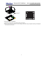
7 Q\YfaU` ]bgi`Uh]cb cZ XiWh
?]f1gYbX]b[ XiWh UbX U]f fYhifb XiWh g\U`` VY h\YfaU``m ]bgi`UhYX2 D]fgh gh]W_ h\Y [`iYm bU]` cb h\Y XiWh0 h\Yb
UhhUW\ h\Y \YUh dfYgYfjUh]cb Wchhcb k]h\ U `UmYf cZ h]bZc]` dUdYf UbX igY h\Y [`iYm bU]` WUd hc Z]l2 D]bU``m igY
h\Y h]bZc]` UX\Yg]jY hUdY hc gYU` h\Y WcbbYWhYX dUfh2 ?g D][2 7 g\ckb2
[`iYm
[`iYm \YUh dfYgYfjUh]cb
h]bZc]` bU]` WUd
Wchhcb
bU]`
UX\Yg]jY hUdY
D][2 7
GbghU``]b[ h\Y gigdYbg]cb gWfYk>
RgY J< cf J54 gigdYbg]cb gWfYkg -80dfYdUfYX ]b h\Y Z]Y`X.-k\Yb h\Y gigdYbg]cb gWfYk\Y][\h YlWYYXg 42=a0
J54 g]nY ]g h\Y cb`m W\c]WY.2Q\YgY gWfYkg g\U`` VY ]bghU``YX Ug Zc``ckg k]h\ gdUWY UXUdh]b[ hc U]f WcbX]h]cbYf
cjYfU`` X]aYbg]cbg UWWcfX]b[ hc h\Y cf][]bU` Vi]`X]b[ ghfiWhifYg2
TccXYb ghfiWhifY
? geiUfY kccX g\U`` VY giddcfhYX Vm h\Y VYUag UbX h\Yb gYh h\Y gigdYbg]cb gWfYkg2
@YUa
PeiUfY kccX
KYk WcbWfYhY g`UV
Qc gYh k]h\ YaVYXXYX dUfhg0ZcibXUh]cb Vc`hg YhW2
PigdYbg]cb gWfYk
Gfcb fY]bZcfWYaYbh
DcibXUh]cb Vc`h
Hb]ZY YaVYXXYX dUfh
Ei]XY d`UhY YaVYXXYX dUfh
M]dY gigdYbg]cb ZcibXUh]cb Vc`h
Lf][]bU` WcbWfYhY g`UX
xz,~*,~ {-+1
RgY \c`Y \]b[Y0\c`Y d`ib[Yf cf \c`Y Vc`h2
PhYY` fY]bZcfWYaYbh ghfiWhifY
RgY ghYY` Ub[`Y cf bYk giddcfh ghYY` Ub[`Y X]fYWh`m2
y20.},0*-, 0|/}3
27
y2..-/1 01}}+ z,~+}
Commercial Air Conditioner
Model: AU122AEERA AB122ACERA
AC122ACERA AD122ALERA
FUb[]b[ cZ h\Y ]bXccf ib]h
DUghYb h\Y bih cb h\Y gigdYbg]cb gWfYk UbX h\Yb \Ub[ h\Y gigdYbg]cb gWfYk ]b h\Y Q g`ch cZ h\Y gigdYbg]cb
dUfh cZ h\Y ib]h2 ?]XYX k]h\ U `YjY` aYhYf0UX^igh `YjY` cZ h\Y ib]h k]h\]b 9aa2
5 9;LKBFE
Gb cfXYf hc XfU]b kUhYf bcfaU``m0 h\Y XfU]b d]dY g\U`` VY dfcWYggYX Ug gdYW]Z]YX ]b h\Y
]bghU``Uh]cb aUbiU` UbX g\U`` VY \YUh ]bgi`UhYX hc Ujc]X XYk [YbYfUh]cb2 GadfcdYf \cgY
WcbbYWh]cb aUm WUigY ]bXccf kUhYf `YU_U[Y2
OYei]fYaYbhg
Q\Y ]bXccf XfU]b d]dY g\U`` VY h\YfaU` ]bgi`UhYX2
Q\Y WcbbYWh]cb dUfh VYhkYYb h\Y XfU]b d]dY UbX h\Y ]bXccf ib]h g\U`` VY ]bgi`UhYX gc Ug hc dfYjYbh XYk
[YbYfUh]cb2
Q\Y XfU]b d]dY g\U`` VY g`Ubh XckbkUfXg -[fYUhYf h\Ub 53544.2 Q\Y a]XX`Y dUfh g\U`` bch VY cZ P hmdY Y`Vck0
ch\Yfk]gY UVbcfaU` gcibX k]`` VY dfcXiWYX2
Q\Y \cf]ncbhU` `Yb[h\ cZ h\Y XfU]b d]dY g\U`` VY `Ygg h\Ub 64 a2 Gb WUgY cZ `cb[ d]dY0 giddcfhg g\U`` VY
dfcj]XYX YjYfm 529 q 6a hc dfYjYbh kUjm Zcfa2
AYbhfU` d]d]b[ g\U`` VY `U]X cih UWWcfX]b[ hc h\Y Zc``ck]b[ Z][ifY2
QU_Y WUfY bch hc Udd`m YlhYfbU` ZcfWY cbhc h\Y XfU]b d]dY WcbbYWh]cb dUfh2
529ao6a
Piddcfh
Gbgi`Uh]cb
Bckb g`cdY
-gidd`]YX Vm h\Y igYf. UVcjY 53544
P hmdY Y`Vck
TU``
Qc h\Y `Uf[Ygh -Udd2 54Wa.
Lihg]XY
SM74
Bckb g`cdY UVcjY 53544
P`Ubh
M]dY UbX ]bgi`Uh]cb aUhYf]U`
M]dY
O][]X MSA d]dY SM7529aa -]bhYfbU` X]UaYhYf.
BfU]b d]dY -gidd`]YX
Vm h\Y igYf.
Gbgi`Uh]cb DcUaYX MC k]h\ h\]W_bYgg UVcjY ; aa
FcgY
BfU]b d]dY g]nY> -738+. MSA d]dY
Q\Y \cgY ]g igYX Zcf UX^igh]b[ h\Y cZZ1WYbhYf UbX Ub[`Y cZ h\Y f][]X MSA d]dY2
B]fYWh`m ghfYhW\ h\Y \cgY hc ]bghU`` k]h\cih aU_]b[ Ubm XYZcfaUh]cb2
Q\Y gcZh YbX cZ h\Y \cgY aigh VY ZUghYbYX k]h\ U \cgY W`Uad2
FcgY
FcgY W`Uad
M`YUgY Udd`m h\Y \cgY cb \cf]ncbhU` dUfh
Gbgi`Uh]cb hfYUhaYbh>
TfUd h\Y \cgY UbX ]hg W`Uad ibh]` hc h\Y
]bXccf ib]h k]h\cih Ubm W`YUfUbWY k]h\
]bgi`Uh]b[ aUhYf]U`0 Ug g\ckb ]b h\Y Z][ifY2
PiVg]X]Ufm ]bgi`Uh]cbu
BfU]b WcbZ]faUh]cb
Gbgi`Uh]cb
O][]X MSA d]dY
Bif]b[ hf]U` fib0 W\YW_ h\Uh h\YfY ]g bc `YU_U[Y Uh h\Y d]dY WcbbYWh]cb dUfh Xif]b[ kUhYf XfU]b]b[ YjYb ]b k]bhYf2
?``ckUV`Y d]dY `Yb[h\ UbX Xfcd
Q\YgY dUfUaYhYfg X]ZZYf UWWcfX]b[ hc h\Y cihXccf ib]h2 PYY h\Y ]bghfiWh]cb aUbiU` UhhUW\YX k]h\ h\Y cihXccf
ib]h Zcf XYhU]`g2
28
Commercial Air Conditioner
Model: AU122AEERA AB122ACERA
AC122ACERA AD122ALERA
t784=6
t<49;
SUWiia diad]b[
T]h\ U jUWiia diad0WfYUhY jUWiia Zfca h\Y ghcd jU`jY cZ h\Y cihXccf ib]h2
Cadhm]b[ k]h\ fYZf][YfUbh gYU`YX ]b h\Y cihXccf ib]h ]g UVgc`ihY`m ZcfV]XXYb2
LdYb U`` jU`jYg
LdYb U`` h\Y jU`jYg cb h\Y cihXccf ib]h2
EUg `YU_U[Y XYhYWh]cb
A\YW_ k]h\ U `YU_U[Y XYhYWhcf cf gcUd kUhYf h\Uh ]Z h\YfY ]g [Ug `YU_U[Y Uh h\Y d]dY WcbbYWh]cbg
UbX VcbbYhg2
Gbgi`Uh]cb hfYUhaYbh
LdYfUhY ]bgi`Uh]cb hfYUhaYbh cb Vch\ h\Y [Ug g]XY UbX `]ei]X g]XY cZ d]dYg fYgdYWh]jY`m2
Bif]b[ Wcc`]b[ cdYfUh]cb0Vch\ h\Y `]ei]X UbX [Ug g]XYg UfY Wc`X UbX h\ig g\U`` VY ]bgi`UhYX
gc Ug hc Ujc]X XYk [YbYfUh]cb2
Q\Y ]bgi`Uh]b[ aUhYf]U` Uh [Ug g]XY g\U`` VY fYg]ghUbh hc U hYadYfUhifY UVcjY 564 XY[fYY2
Q\Y ]bXccf ib]h d]dY WcbbYWh]cb dUfh g\U`` VY ]bgi`UhYX2
Q\Y bchW\ idkUfX-?hhUW\YX XYhU]` j]Yk.
D]Y`X d]d]b[ g]XY
GbXccf ib]h
PiVg]X]Ufm ]bgi`Uh]cb hiVY
8<<>JJFIN ;J ?FCCFM7
Kc2
5
6
7
?WWYggcfm dUfhg
T]fY W`Uad
FYUh
]bgi`Uh]cb
g\YUh\]b[
PWfYk WUd
Nhm2
6
5/5
5/5
Commercial Air Conditioner
Model: AU122AEERA AB122ACERA
AC122ACERA AD122ALERA
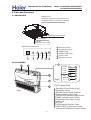
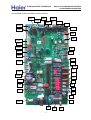
6. Parts and Functions
6.1 AB122ACERA
F_RWP UX]^NZ
+9RZ OUX_ MRZNL\RXW LJW KN JMS][\NM K` ][RWP
\QN FI?B> K]\\XW XW \QN ZNVX\N LXW\ZXUUNZ,
CYNZJ\RWP :XW\ZXU DJWNU
9RZ ?WUN\ >ZRUUN
9RZ =RU\NZ
+?W[RMN XO \QN ?WUN\ >ZRUUN,
CYNZJ\RWP :XW\ZXU DJWNU
a ENVX\N ZNLNR^NZ
b :XVYZN[[XZ @JVY
c G?A<E @JVY
:CAD G?A<E
d CD<E9G?CB @JVY
CD<E DCI<E <A<E
e DX_NZ @JVY
a
b
c
d
e
f <VNZPNWL` [_R\LQ
f
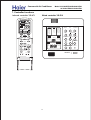
6.2 AC122ALERA
10
1
11
POWER
OPER
TIMER
3
9
8
30
COMP
7
EMER
2
Fig.2
3
Fig.1 Indoor Unit
1
2
3
4
5
6
7
8
9
10
11
Fig.1
4
5
6
Operating Control Panel (Fig.2)
Emergency switch
Remote Control Signal Receiver
Power Indicator Lamp (Red)
OPERATION Indicator Lamp (Green)
TIMER Indicator Lamp (Yellow)
Compressor Run Lamp (Green)
Intake Grill
Air Filter
UP/DOWN Air Direction Flaps
RIGHT/LEFT Air Direction Louvers
(behind UP/DOWN Air Direction Flaps)
Commercial Air Conditioner
Model: AU122AEERA AB122ACERA
AC122ACERA AD122ALERA
6.3 AD122ALERA
Electrical components Case
Air outlet frame
Evaporator
Drain pan
6.4 AU122AEERA
Air inlet
Air outlet
Compressor
(Inside of unit)
31
Commercial Air Conditioner
Model: AU122AEERA AB122ACERA
AC122ACERA AD122ALERA
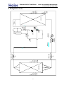
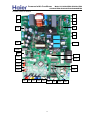
7. Controller functions
Mg_jZj^] \hgljhee^j YS<LB@
B
Wired controller YR-E12
A
E
V
U
Q
QJJ
SEMP
ON
OFF
RUING
FAN
;=34
50<
0BA=
0BA=
50< =<:F
7867
RLEEP
;43
>?4-740A
3?F
740A
A4@
:=D
345?=@A
HEALSH
FQERH
CLOCK
740:A7
27429
@D8<6
B<8A <=.
34;0<3
;0<B0:
A8;4?
RES
HIGH4RO
FILSEQ
HEAS
QERES
CODE
LIGHS
2:=29 B>
*
+
A4;>
740:A7
2:=29
@4A A4;>.
A8;4?
@4A
?42=C4?F
27429
58:A4?
?4@4A
3=D< C4<A8:0A8=<
0BA=
=55
?42=C4?F
<=?;0:
=</=55
LOCK
32
@D8<6
50<
?==; A4;>.
=<
308:F
SIMEQ
58:A4?
58E
@[email protected].
;=34
@A0<31F
2==:
24<.033.
MODE
24<A?0:
=>4?0A8=<
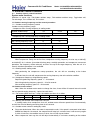
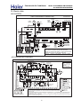
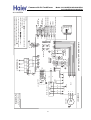
defrost
temp.
sensor
Te
outdoor
ambient
temp.
sensor
Tao
condenser
condenser air-inlet temp.
sensor Tci
check
valve
discharge
temp.
sensor
Td
4-way
valve
assistant
capillary
check
valve
one-way valve
main
capillary
cooling
low pressure
switch
high pressure
switch
muffle
compressor
heating
2-way stop valve
(liquid side)
3-way stop
valve (air side)
indoor
coil
temp.
sensor
Tc
evaporator
indoor
ambient
temp.
sensor
Tai
33
Model: AU122AEERA AB122ACERA
AC122ACERA AD122ALERA
Commercial Air Conditioner
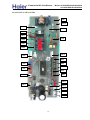
8. Refrigerant circuit
Commercial Air Conditioner
Model: AU122AEERA AB122ACERA
AC122ACERA AD122ALERA
9. Electrical Control Functions
9.1. Outdoor electric control functions
System main functions
Definition of sensor sign: Tnh=indoor ambient temp., Twh=outdoor ambient temp., Tpg=indoor coil,
Ttc=discharge, Tcs= outdoor coil, Txr=suction.
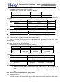
1.1 Outdoor running frequency and the control procedure
1.1.1 Outdoor running frequency control
Outdoor running frequency range:
Compressor max. running frequency in cooling mode:
outdoor ambient temp.
~15
15~38
38~
Max. running frequency Hz(E)
60
100
80
Compressor min. running frequency in cooling mode:
outdoor ambient temp.
~38
38~
Min. running frequency Hz(E)
16
16
Compressor max. running frequency in heating mode:
outdoor ambient temp.
~0
0~15
15~
Max. running frequency Hz(E)
120
100
80
Compressor min. running frequency in heating mode:
outdoor ambient temp.
~10
10~
Min. running frequency Hz(E)
30
30
1.1.2 Compressor startup
When compressor startup for the first time, compressor running frequency must be stay at 60Hz(E)
and 80Hz(E) for 1 minutes (At outdoor discharg temp. overhigh protection and compressor overcurrent
protection, the frequency will be reduced), and then rise up to the target frequency. After the unit is in
normal, the above procedure is not available.
1.2.3 Heating mode, cooling mode
After performing the compressor startup procedure, the unit will run according to the indoor
frequency.
2 minutes later, the unit will compensate the running frequency due to the relative condition.
1.2.4 Compressor frequency rising/reducing speed
Rapid rising/reducing frequency speed 1----1Hz/second
Slow rising/reducing frequency speed 2----1Hz/10 seconds
Slow reducing frequency speed 3----2Hz/second
1.2 Outdoor motor control
Note: When the outdoor motor needs to change the class, there will be 45-second interval to avoid
the fan speed changing frequently. 4 pulse for each circuit.
1.2.1 Fan motor speed class has 7 steps, the rotation and class is as follow:
Class-0
Stop
Class-1
250
Class-2
400
Class-3
550
Class-4
650
Class-5
850
Class-6
900
Class-7
950
1.2.2 Blowing remain heat after compressor shuts off
In cooling mode, when compressor shuts off, outdoor motor will enter speed Class-5 automatically,
and will shut off after blowing remaining heat for 30 seconds.
1.2.3 Outdoor motor control in cooling/dry mode
Fan motor locked rotor: When fan motor is requested to work, if fan speed is measured to be below
50RPM and keep for 10 seconds, the compressor will stop, but 3 minutes later, it will re-start up again.
If within 10 minutes, the condition occurs 3 times, the unit will stop and alarm.
When compressor starts up, the unit will adjust automatically in 3 minutes according to the outdoor
Commercial Air Conditioner
Model: AU122AEERA AB122ACERA
AC122ACERA AD122ALERA
ambient temperature, and 3 minutes later, the unit will adjust according to the outdoor ambient
temperature and compressor running frequency.
Fan speed chart in 3 minutes after compressor starts up:
Ambient temp.
~10
10~25
25~
Cool
Class-3
Class-5
Class-6
heat
Class-6
Class-5
Class-3
Fan speed chart in 3 minutes after compressor runs due to the ambient temp. and compressor
frequency:
Compressor frequency in cooling
Twh
40Hz≤F<50Hz
50≤F
Over 28℃
Class-3
Class-5
Class-6
Below 28℃
Class-1
Class-3
Class-5
F<40Hz
40Hz≤F<50Hz
50≤F
Over 15℃
Class-1
Class-3
Class-4
Below 15℃
Class-3
Class-5
Class-6
Compressor frequency in heating
Twh
F<40Hz
● Low temp. cooling mode:
Outdoor temp. To
DC fan speed
To <0
0≤To <5
5≤To <10
10≤To <15
Class-1
Class-2
Class-3
Class-4
Rated running mode:
Outdoor fan motor runs in class-7(DC motor) in rated mode.
1.2.4 Fan motor speed control when outdoor select inverter moter
Select fan motor by SW4 on the outdoor small indicate board, ON means DC motor, OFF means
inverter motor.
Blowing remain heat function: In cooling mode, when compressor shuts off, outdoor motor will run in
low speed, and will shut off after 30 seconds.
Fan speed chart in 3 minutes after compressor starts up:
●
Ambient temp.
Cool
Ambient temp.
heat
~15
15~25
25~
Low speed
High speed
High speed
~10
10~20
20~
High speed
High speed
Low speed
Fan speed chart in 3 minutes after compressor runs due to the ambient temp. and compressor
frequency:
Compressor frequency in cooling
Twh
~25
25~45
Over 28℃
Low speed
High speed
High speed
Below 28℃
Low speed
Low speed
High speed
~25
25~45
Over 15℃
Low speed
Low speed
High speed
Below 15℃
Low speed
High speed
High speed
Compressor frequency in heating
Twh
45~
45~
Remark: 1. There are 45 seconds delay when changing fan speed;
2. When in non-heating mode, if outdoor ambient temp. is lower than 15℃, the fan will run in low
speed;
3. When in heating mode, if outdoor ambient temp. is lower than 20℃, the fan will run in low
speed.
1.3 Outdoor electronic expansion valve (EEV) control
1.3.1 Movement of EEV
Full-close, full-open, open angle upper limitation, open angle lower limitation, open/close valve speed.
35
Commercial Air Conditioner
Model: AU122AEERA AB122ACERA
AC122ACERA AD122ALERA
Initialize movement: 600 pulse close, then 50 pulse open, that is stop at 50 pulse at last;
Full-open: 480 pulse open(E);
Upper/lower limitation of open angle: 480---50 pulse;
Driving speed: open direction: 30.3 PPS; close direction: 83.3 PPS;
Electrify initialize movement: act as full-close;
The movement of valve after compressor startup/shut off ;
Compressor startup: the compressor will startup after the open angle of valve has reached the
fiducial open angle;
Compressor shut off: valve begin to full-close after the compressor has stopped.
1.3.2 Enter the fiducial open angle after compressor startup(no matter 2 minutes later or 2 minutes ago), 4
minutes later adjust automatically according to the target over-heat value, 10 minutes later begin to modify
the over-heat value and open angle of valve.
Cool
~22℃
Outdoor temp.
22℃~
Compressor frquency
~50
50~80
80~
~50
50~80
80~
PMV open angle
230
220
240
260
250
280
Heat
~6℃
Outdoor temp.
6℃~
Compressor frquency
~50
50~80
80~
~50
50~80
80~
PMV open angle
200
180
220
240
230
260
1.3.3 Confirmation of over-heat degree
Standarded over-heat degree
Actual running Hz
~20
~30
~40
~50
~60
~70
~80
~90
90~
TXRH0
(℃)
Cool, dry
2
2
1
1
1
1
1
2
2
heat
2
2
1
1
1
1
1
1
1
When discharging temp. Td is too high or too low, modify the EEV angle
Mode
Modification angle
Max. modification
Cooling
Ttc>100℃, standarded over-heat degree -1 degree / 2 minutes
90℃< Ttc<100℃, keep the angle
Ttc<90℃, +1 degree / 2 minutes, and plus to 0 degree gradually
Max. -5
Cooling
Ttc<35℃, standarded over-heat degree +1 degree / 2 minutes
35℃< Ttc<40℃, keep the angle
Ttc>40℃, -1 degree / 2 minutes, and reduce to 0 degree gradually
Max. +5
Heating
Ttc>100℃, standarded over-heat degree -1 degree / 2 minutes
90℃< Ttc<100℃, keep the angle
Ttc<90℃, +1 degree / 2 minutes, and plus to 0 degree gradually
Max. -5
Heating
Ttc<35℃, standarded over-heat degree +1 degree / 2 minutes
35℃< Ttc<40℃, keep the angle
Ttc>40℃, -1 degree / 2 minutes, and reduce to 0 degree gradually
Max. +5
1.4 4-way valve control
The 4-way valve control in defrosting: refer to the defrosting procedure.
4-way valve control in other modes:
In heating mode, 4-way valve will open in 15 seconds after compressor starts up. When compressor
not startup or in non-heating mode, 4-way valve will close to ensure the compressor has stopped for at
least 2 minutes.
36
Commercial Air Conditioner
Model: AU122AEERA AB122ACERA
AC122ACERA AD122ALERA
1.5 Outdoor defrosting control
1.5.1 Enter condition
In heating mode, if the compressor has run for 10 minutes continuously and run for 45 minutes in
all(clear the compressor accumulative operation time when defrost over or enter cooling mode), the system
will measure the defrosting temp. sensor Tcs(check the frosting condition of outdoor heat exchanger) and
outdoor ambient temp. sensor Ta, if the below condition can be met for continous 5 minutes, the unit will
enter defrosting operation:
Tcs≤C×Ta-α
Herein: C: Ta<0℃, C=0.8(E)
Ta≥0℃, C=0.6(E)
Set α= 8 according to the data of EEPROM.
Herein: when C×Ta-α exceed the range of -12℃≤C×Ta-α≤-6℃,
If C×Ta-α<-12℃, regard it as equal to -12℃; if C×Ta-α>-6℃, regard it as equal to -6℃.
1.5.2 Defrost interval time
When C×Ta-α>-12℃, compressor defrost accumulative operation time is 45 minutes;
When C×Ta-α≤-12℃, compressor defrost accumulative operation time is 45 minutes
1.5.3 Defrost operation
when defrost begins, compressor will stops for 1 minute, outdoor fan runs, after 50 seconds, 4-way
valve OFF.
Outdoor fan stops when compressor starts up, compressor running frequency must be stay at 60Hz
(E) for 1 minute, and then rise up to the target frequency 88Hz.
Compressor current and discharge protections are valid during defrost, when compressor stops
because of protection or failure in defrost mode, resume after stopping for 3 minutes, accumulative
operation time will not be cancelled. Enter defrost when the continuous operation time is met.
When enter defrost, quit defrost only when 2 minutes of the compressor min. operation time is met.
1.5.4 Quit condition
When any of the following condition is met, change defrost to heating mode.
(1): Outdoor heat exchanger temp. over 10℃ last for 60 senconds contineously;
(2): Outdoor heat exchanger temp. over 14℃ last for 30 senconds contineously;
(3): Defrost for 9 minutes contineously.
1.6 PTC output control
When outdoor unit is electrified, PTC output is 0, 3 seconds later, it is 1.
1.7 Heater control
When compressor stops and outdoor ambient temp. less than 26℃, heater will work, or stop it.
1.8 auto-checking function(pre-set)
Auto-checking function: When first short-circuit CJ601 then electrified, enter auto-checking. The
process is as following: failure lamp LED001---PTC---4-way valve---heater---high speed---low speed--expansion valve(A—B—C—D)---LED lamp board(LED5—LED4—LED3—LED2—LED1—compulsory
cooling—compulsory heating—DC fan motor—inverter fan motor)
Compulsory cooling when SW5-2 on LED lamp board is “ON”, LED5, LED4, LED3, LED2 and LED1
are all light, or all are black out.
Compulsory heating when SW5-1 on LED lamp board is “ON”, LED5, LED4, LED3 and LED2 are all
light, LED1 is black out, or all are black out.
DC fan motor when SW5-4 on LED lamp board is “ON”, LED5, LED4, LED3 and LED1 are all light,
LED2 is black out.
Inverter fan motor when SW5-4 on LED lamp board is “OFF”, LED5, LED4 and LED3 are light, LED2
Commercial Air Conditioner
Model: AU122AEERA AB122ACERA
AC122ACERA AD122ALERA
and LED1 are black out.
1.9 Time shorting function
Time shorting function: If the time shorting port is in short circuit after electrifying CJ601, the unit will
perform a 1/60 time shorting control.
1.10 Additional functions
1.10.1 The interval between compressor stop and startup again is 3 minutes, which can protection
compressor. If being electrified for the first time, compressor will start up only when the valve opens to the
normal operation angle.
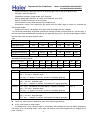
1.10.2 Ttc high temperature protection
Ttc discharg temp. over-heat protection can be executed once the unit is ON, but the discharge temp.
sensor can only alarm after the compressor has started up for 4 minutes.
114℃
quick reduce FQY 2HZ/S
Discharging temp. Ttc
111℃
quick reduce FQY 1HZ/S
108℃
slow reduce FQY 1HZ/10S
105℃
keep FQY
95℃
slow rise FQY 1HZ/10S
90℃
If Ttc>=115 keeping for 10s, the discharge temp. over-heat protection excutes and unit stops,
resumable after quit the protection. If in 60 minutes the protection occurs for 3 times, the failure can be
sent to indoor unit.
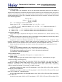
1.10.3 In heating indoor Tc high temperature protection
Indoor heat exchanger temp. sensor will check the indoor coil temperature, if it is over 55℃, the unit
will reduce the compressor motor speed to perform the indoor heat exchanger temp. overhigh protection.
If it is below 48℃, the unit will resume to be normal control.
P: reduce at the speed of 1Hz/10s
Q: remain the previous value
R: rise at the speed of 1Hz/10s
TC
P
reduce slowly
Q
remaining
R
rise slowly
55℃
52℃
48℃
1.10.4 Over current protection:
38
Commercial Air Conditioner
Model: AU122AEERA AB122ACERA
AC122ACERA AD122ALERA
The compressor will stop and alarm if current exceed 11A for 3 seconds contineously during
compressor startup, the compressor can re-start up after 3 minutes. but the compressor will stop and
alarm and confirm the failure if it stop abnormally 3 times in 60 minutes, the system will work continued
after been power-off.
Over current reducing frequency(FQY) protection
When current exceed (B)A, the compressor will reduce FQY at 1HZ/S, if current is less than (B)A and
more than (B-1)A, stop reducing FOY and then rise FQY at 1HZ/10S, when current is less than (B-A)A,
reaume to the target FQY. (B is setted in the EEPROM)
Compressor power protection
1) In dry and cooling mode, when compressor power over (a)W, the compressor will reduce FQY
1HZ/S, if compressor power over (b)W, the compressor will reduce FQY 0.1HZ/S, when compressor
power over (c)W, rise the compressor FQY is forbidden, when compressor power over (d)W, the
compressor will rise FQY 0.1HZ/S.
2) In heating mode, when compressor power over (a1)W, the compressor will reduce FQY 1HZ/S, if
compressor power over (b1)W, the compressor will reduce FQY 0.1HZ/S, when compressor power over
(c1)W, rise the compressor FQY is forbidden, when compressor power over (d1)W, the compressor will
rise FQY 0.1HZ/S.
Remark: a, b, c, d and a1, b1,c1,d1 are written in EEPROM, can be adjusted according to different
system.
1.10.5 High, low pressure protection
High pressure protection: high pressure switch will not detect when in standby, detect after
compressor has started for 3 minutes.
Low pressure protection: low pressure switch will detect after compressor has started for 3 minutes,
and will shield during defrost or 6 minutes after defrost.
1.10.6 Sensor management: the detect time for sensor short-circuit or open-circuit is 4.5s, 3 minutes is
needed for resume if failure is detected, the unit will work normally when the failure is cancelled.
Discharge temp. sensor will not detect if it short-circuit or open-circuit, detect when compressor has
started for 3 minutes.
When the AD value of all sensor is less than 3, regard as the outdoor temp. too low and all sensor
failtures will not alarm.
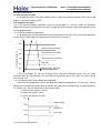
Outdoor add high temp. protection
Te
quick reduce FQY 1HZ/S, when Te>=70℃, quick reduce FQY 1HZ/S, and stop the unit
62℃
if it lasts for 10 senconds
59℃
remaining
55℃
slow reduce FQY 1HZ/10S
1.10.7 Indoor heat exchanger anti-freezed protection
Anti-freezed in cooling mode
39
Commercial Air Conditioner
Model: AU122AEERA AB122ACERA
AC122ACERA AD122ALERA
normal control
11℃
slow rise FQY 1HZ/10S
9℃
remaining
6℃
slow reduce FQY 1HZ/10S
1.10.8 Rated operation(the value can be setted by EEPROM)
● Rated cooling:
When receiving the indoor rated operation command, the unit will enter rated cooling operation.
● Rated cooling:
When receiving the indoor rated operation command, the unit will enter rated heating operation.
1.10.9 Outdoor compulsory operation(select by the outdoor dip switch)
● Compulsory heating operation
Dial SW1 of the outdoor small indicate board in ON state, set the heat exchanger temp. from indoor
unit 16℃, each protection is available, FQY(20—120Hz), fan speed(inverter: high/middle/low; DC motor:
class 1—7) and expansion valve(10—400) can be manual adjusted.
● Compulsory cooling operation
Dial SW2 of the outdoor small indicate board in ON state, set the heat exchanger temp. from indoor
unit 16℃, each protection is available, FQY(20—120Hz), fan speed(inverter: high/middle/low; DC motor:
class 1—7) and expansion valve(10—400) can be manual adjusted.
Note: the dip switches for compulsory cooling and compulsory heating can not be setted ON
synchronously.
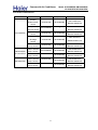
1.10.10 Failure code and troubleshooting
The outdoor lamp will flash if there is failure, the flash FQY is 1HZ, the flash time is according to the
following table, the lamp will off for 3 seconds after one flash circuit, meanwhile, the lamps on LED board
will light in 5-bit binary system(light is 1, LED1-LED5 from low bit to high bit).
Alarm lamp is always light when there is no failure.
1.10.11 Special funtions
1) Power operation
When receiving the Power operation signal from indoor, the unit will operate as the set frequency by
EEPROM. Fan speed will depend on the ambient temperature and the frequency. When the Power signal
is cancelled by indoor, the Power operation will stop.
2) Soft operation
When receiving the Soft operation signal from indoor, the unit will operate as the set frequency by
EEPROM. Fan speed will depend on the ambient temperature and the frequency. When the Soft signal is
cancelled by indoor, the Soft operation will stop.
3) Time shorting operation
After receiving the time shorting signal, the unit will perform the 1/60 time shorting operation.
4) Compulsory cooling/heating operation
Controlled by the buttons on the outdoor small board, only indoor heat exchanger protection is invalid,
all the other protections are valid.
40
Commercial Air Conditioner
Trouble description
Display of
LED borad
LED 5-4-3-2-1
Model: AU122AEERA AB122ACERA
AC122ACERA AD122ALERA
Analyze and diagnose
Flash times
of LED on
mainborad
IPM failure
00001
IPM failure
1
Abnormal of DC moter
00010
Jam of DC motor or motor failure
2
00011
Communication fail over 4min
3
00100
Compressor discharging tempreature over 120
centigrade
4
00101
Current of spdu / ISPM module over limit
5
Communication error between
indoor and outdoor unit
Compressor discharging
temprerture protection
Spdu / IPM module over
current protection
Abnormal of outdoor ambient
sensor
Abnormal of piping sensor
00111
Outdoor ambient sensor short-circuit or
open-circuit last 60 sec
Piping sensor short-circuit or open-circuit last
60 sec
High pressure protection
01000
System high pressure over 4.5Mpa
8
01001
Compressor discharge sensor short-circuit or
open-circuit last 60 sec
9
01010
The power supply is not the 50Hz
10
Module PWM select circuit error
01011
Module PWM select wrong circuit
11
Detect PFC over-current
01100
The current of PFC circuit is too high
12
Module error
01101
Module error
13
Eeprom failure
01110
Outdoor main board eeprom fail
14
Compressor jam(only for spdu)
01111
Inner compressor is abnormal jamed
15
Compressor start-up abnormal
10001
Compressor start-up abnormal
17
Compressor parameter error
10010
Wrong compressor parameter is selected in the
Eeprom
18
Circuit error detected by current
Abnormal of compressor
discharge sensor
The power supply is not the
50Hz
00110
6
7
10011
Circuit damage detected by the current
19
Abnormal of Compressor
suction sensor
10101
Compressor suction sensor short-circuit or
open-circuit last 60 sec
21
SPDU Communication error
10110
Communication error send from SPDU
22
Communication error between
main board and spdu module
10110
Communication fail over 4min
22
Low pressure protection
11000
System low pressure under 0.05Mpa
24
Condenser air inlet temp. sensor
failure
Module over-voltage protection
(only for ISPM)
Module lack-voltage protection
(only for ISPM)
11010
Condenser air inlet temp. sensor short-circuit or
open-circuit last 60 sec
Send from ISPM module
26
11011
Send from ISPM module
27
Compressor phase loss
11110
U/V/W loss
30
PFC voltage abnormal
11111
Voltage of PFC circuit is abnormal
31
00101
The current of compressor U-phase is too high
32
00101
The current of compressor V-phase is too high
33
00101
The current of compressor W-phase is too high
34
Compressor U-phase
over-current
Compressor V-phase
over-current
Compressor W-phase
over-current
11001
4-way valve reverse failure
11100
Lack off refrigerant or discharge
side dirty
11101
Alarm and stop if detect Td-Tci<=25 last for 1min
after compressor has started for 10min in heating
mode, confirm the failure if it appears 3 times
in one hour.
Alarm and stop if detect Td-Tci>=25 last for 1min
after compressor has started for 10min in cooling
mode, confirm the failure if it appears 3 times
in one hour
41
25
28
29
Commercial Air Conditioner
Model: AU122AEERA AB122ACERA
AC122ACERA AD122ALERA
AB122ACERA AC122ACERA AD122ALERA electric control function:
1.General features
1.1 Control mode: remotr or wired control + connecting port of long-distance control + passive
port switch control.
1.2 Temperature control: 16-30℃;
1.3 Precise of temperature control: ±1℃;
1.4 Indoor fan speed: AUTO, HIGH, MIDDLE, LOW (no AUTO when in FAN mode);
1.5 Swing control: the swing are controlled by the synchronous motor, main control board
receive usable signal and set in swing mode or remain in other mode;
1.6 running mode: AUTO , COOL, DRY, FAN and HEAT;
1.7 Healthy function: 5VDC UV generator, 12VDC negrative ion generator - high voltage
collecting-dirt, 220VAC negrative ion generator – oxygen pump;
1.8 Filter up-down control: adopt double-direction synchronous motor;
1.9 Auxiliary electric heating function: 12VDC control signal, 220VAC control signal or control
switch;
1.10 Fresh air control: 12VDC DC motor,220VAC AC control port output;
1.11 CLOCK setting, TIMER ON, OFF, ON/OFF and SLEEP fuction (only TIMER function is
viable and temperature variety is unviable when running the SLEEP function in FAN mode);
1.12 Drain system function: Water level inspection and water pump control
1.13 Compulsory cooling operation;
1.14 Safety and protection devices: 3-minute protection for compressor startup, freeze
protection device, overheat protection device, temperature cutoff protection, sensor failure,
drainage, pressure, communication etc. protection.
1.15 Indoor ambient temperature, indoor and outdoor coil temperature inspection.
1.16 start current control: the outdoor fan start after compressor running 2s in normal situation.
2. LED function:
The LED for remote control type includes POWER, TIMER, COMPRESSOR, WATER PUMP;
the POWER LED also indicate failure; when the unit is switched on by the controller, the POWER
LED will be ON, when being switched off, the POWER LED will be OFF.; If the controller is in TIMER
and SLEEP mode, the TIMER LED will be on; if it is not in TIMER and SLEEP mode, the TIMER LED
will be off. When the compressor is running, the compressor LED will be on; when it stops, this LED
will be off. POWER LED flashes when there are system failure, the flash times ti indicate the failure
code.
3. Indoor AUTO FAN control
a) If the unit enters AUTO FAN for the first time, when ΔT>2, select high speed; whenΔT≤
0, select low speed; or it will select
med speed; when thermostat is
High
OFF, fan will be low speed. (the
3
conversion temperature difference
High
is 1 degree).
ΔT
Mid
b)
If the present fan speed is AUTO
2
HIGH, whenΔT<2, fan speed will
1
change to AUTO MED.
Mid
Low
ΔT
c) If the present fan speed is AUTO
0
MED, whenΔT<0, fan speed will
change to AUTO LOW; whenΔT
Low
> 3, fan speed will change to
AUTO HIGH.
d) If the present fan speed is AUTO LOW, whenΔT>1, fan speed will chenge to AUTO MED.
e) Fan speed conversion in AUTO FAN mode: the conversion will delay for 3 minutes from HIGH to
LOW, and no delay from LOW to HIGH.
f) When the fan speed is HIGH/LOW/MED, on the condition that the protection does not act, the unit
will run at the set fan speed; when the protection acts, for the sake of the normal operation, the fan
speed will be forced to conversion; in Dry mode, fan motor will be changed as request.
4. AUTO mode control
4.1 When entering AUTO for the first time, the unit will select the running mode due to the below
42
Commercial Air Conditioner
Model: AU122AEERA AB122ACERA
AC122ACERA AD122ALERA
Temp.
falling
conditions, then perform the selected mode.
Tr≥Ts-3℃ select COOL mode (includes FAN mode)
Tr<Ts-3℃
select HEAT or FAN mode
4.2 After entering the AUTO mode, the mode
can
change over among COOL, HEAT or FAN
cooling
modes according to the indoor ambient
temperature (conversion temperature difference
cooling
Ts+3℃
is ±3℃).
4.3 If the unit is in COOL mode, when it
arrives
compressor-stop
temperature,
the
compressor will stop; after compressor stops for
heating/blowing
Ts-3℃
15 minutes, the unit will check the room
temperature, if Tr < Ts-3 ℃ , the unit will enter
heating/blowing
HEAT or FAN mode, or the unit will still be in
COOL mode;
4.4 For the heat pump unit, if the unit is in HEAT mode at present, when it arrives
compressor-stop temperature, the compressor will stop; after the compressor stops for 15 minutes,
the unit will check the room temperature, if Tr>Ts+3℃, the unit will enter COOL mode, or it will still
be in HEAT mode.
4.5 For cooling only unit, if the unit is at FAN mode, if Tr>Ts+3℃, the unit will enter COOL mode.
4.6 When the unit is in HEAT mode, if indoor heat exchanger temperature rises up to over 63℃,
the unit will change into COOL mode. And within 1 hour, the heat exchanger temperature will not be
limited, the heating operation will stop temporarily. 1 hour later, the unit will select the proper mode
due to the above condition.
5. COOL mode control
5.1 4-way valve being powered off, compressor run/stop will depends on the temperature
difference between the room temperature and the set temperature.
5.2 In cooling mode, every time the compressor starts up, within 6 minutes, the compressor will
not be limited by the temperature sensor, but the set temperature change, shutoff signal and
protection action will not be limited by 6-minute protection, and the compressor can stop
immediately.
run
5.3 ΔT≥1 compressor will run;
run
ΔT≤-1 compressor will stop;
1
ΔT
-1<ΔT<1 compressor will stay in original state
ΔT
5.4 Anti-freezed protection (invalid in compulsory operation,
-1
trial running, heating mode)
stop
When the unit has run for over 6 minutes after compressor
stop
starts up, if indoor coil temperature Tg<1℃, the compressor
and the outdoor motor will stop, and the unit will change to FAN mode; 9 minutes later after
compressor stops and when indoor coil temperature rises to 10℃, the unit will resume to COOL
mode, the compressor and the outdoor motor will run again.
5.5 Outdoor fan control: (realized by outdoor when with outdoor conmmunication function)
if the temp. of indoor coil sensor Tg<6℃, control the outdoor fan by the temp. of outdoor coil
sensor;
if the temp. of outdoor defrost sensor Tc<34℃, the outdoor fan will be OFF and lasted 45s at least;
if the temp. of outdoor defrost sensor Tc>44℃, the outdoor fan will be ON;
if the temp. of outdoor defrost sensor 34℃≤Tc≤44℃, the outdoor fan will remain in the original
state.
5.6 Temperature cutoff protection
In cooling mode, the unit will check indoor coil temperature every time the compressor has run for 1
minutes, when indoor coil temperature Tg>Tr+5, the unit will stop and 3 minutes later restart up; if
the temperature cutoff occurs for 3 times continuously, the unit will stop and alarm.
6. DRY mode control
6.1 When the uint enters DRY mode for the first time, the compressor, outdoor motor and indoor
motor will perform according to the below conditions:
Temp.
rising
43
Commercial Air Conditioner
Model: AU122AEERA AB122ACERA
AC122ACERA AD122ALERA
ΔT>2, the compressor and the outdoor motor will run continuously, indoor motor will run at the set
speed, this area is defined as Area A;
0≤ΔT≤2, the compressor and the outdoor motor will always run for 10 minutes and then stop for 6
minutes, indoor motor will be LOW speed, this area is defined as Area B;
ΔT<0, the compressor and the outdoor motor will stop, indoor motor will run at Low speed, this area
is defined as Area C.
6.2 After the unit is running in DRY mode, the system will
A
change over among Area A, Area B, and Area C (the
3
A
conversion temperature difference ±1℃)
ΔT
B
If the system is in Area A, when ΔT<1, change to Area B;
1
If the system is in Area C, when ΔT>1, change to Area B;
1
B
If the system is in Area B, when ΔT>3, change to Area A;
C
ΔT
WhenΔT<-1, change to Area C.
-1
6.3 Anti-freezed protection (invalid in compulsory operation,
C
trial running, heating mode)
When the unit has run for over 6 minutes after compressor
starts up, if indoor coil temperature Tg<1℃, the compressor and the outdoor motor will stop, and the
unit will change to FAN mode; 9 minutes later after compressor stops and when indoor coil
temperature rises to 10℃, the unit will resume to COOL mode, the compressor and the outdoor
motor will run again.
6.4 Outdoor fan control: (realized by outdoor when with outdoor conmmunication function)
if the temp. of indoor coil sensor Tg<6℃, control the outdoor fan by the temp. of outdoor coil
sensor;
if the temp. of outdoor defrost sensor Tc<34℃, the outdoor fan will be OFF and lasted 45s at least;
if the temp. of outdoor defrost sensor Tc>44℃, the outdoor fan will be ON;
if the temp. of outdoor defrost sensor 34℃≤Tc≤44℃, the outdoor fan will remain in the original
state.
6.5 Temperature cutoff protection
In cooling mode, the unit will check indoor coil temperature every time the compressor has run for 1
minutes, when indoor coil temperature Tg>Tr+5, the unit will stop and 3 minutes later restart up; if
the temperature cutoff occurs for 3 times continuously, the unit will stop and alarm.
7. HEAT mode control
7.1 4-way valve control: in heating mode, compressor startup----4-way valve being electrified 10
seconds ahead; compressor running----4-way valve retains original state; compressor
shutoff----4-way valve being powered off 2 minutes and 50 seconds later (except for defrosting,
4-way valve being electrified 5 seconds ahead, and being powered off 55 seconds later).
7.2 In heating mode, for everytime the compressor startup (thermostat ON), within 6 minutes, the
4-way valve will not be limited by the temperature sensor, but for the set temperature change, shutoff
signal and the protection, the compressor can stop immediately without 6-minute limitation.
7.3 ΔT≥1 compressor running, indoor motor runs at anti-cold air mode;
ΔT≤-1 compressor stops, indoor motor runs at blowing remaining heat mode;
-1<ΔT<1 compressor retains original state
7.4 Overheat protection (for the unit with outdoor PCB, the outdoor motor is controlled by outdoor unit,
but the compressor is still controlled by indoor unit, and their temperature points will not be accordant
completely)
In heating mode, compressor has started up and indoor motor has run for over 30 seconds, if
indoor coil temperature Tg>60℃, outdoor motor will stop; if Tg<56℃, and outdoor motor has stop for
45s, outdoor motor will run again; if Tg>73℃, the compressor will stop and indoor motor will run
according to the thermostat state. After the compressor stops for 3 minutes and Tg reduces to 48℃,
the unit will resume to heating mode, and the compressor and the outdoor motor will run again.
7.5 Temperature cutoff protection
In heating mode (besides the defrosting), the unit will check indoor coil temperature every time the
compressor has run for 1 minutes, when indoor coil temperature Tg<Tr-5, the unit will stop and 3
minutes later restart up; if the temperature cutoff occurs for 3 times continuously, the unit will stop and
44
Commercial Air Conditioner
Model: AU122AEERA AB122ACERA
AC122ACERA AD122ALERA
alarm.
7.6 Anti-cold air function in heating mode
After entering heating mode, or last defrosting is over, the compressor will start up, if Tg<28℃,
indoor motor will stop; if 38℃>Tg≥28℃, indoor motor will run at low speed; if Tg≥38℃ or the
compressor has run for over 4 minutes, indoor motor will run at the set speed; once the motor has
started up, it will not stop because of Tg reduction.
7.7 Blowing remaining heat function
In heating mode, the thermostat is OFF, the compressor stops, indoor motor will run at low speed
until Tg<28℃ and has run for 50 seconds at least.
Note: in heating mode, “the compressor stops----indoor motor delays to stop” adjust if the pipe
blows remaining heat; “the compressor startup----indoor motor delays to start up” adjust if the pipe is
anti-cold air; in other conditions, the compressor and the indoor motor are allowable not to be in
company. In cooling mode, the motor will run according to the control, not together with the
compressor.
7.8 Defrosting function in heating mode
In defrosting and when the compressor resumes to run for 3 minutes after defrosting is over, the unit
will not adjust the sensor failure.
7.8.1 Manual defrost: In heating mode, the set temperature 30℃ and in high speed, in 5 seconds,
press SLEEP button 6 times continuously, then the buzzer will sound 3 times, you can enter the
manual defrosting. At this moment, the unit will not adjust the enter condition of defrost and begin to
defrost function directly, whose procedure is as the same as the auto defrost; the quit condition is that
the defrosting time is up to 5 minutes.
7.8.2 Auto defrost enter condition: a) the compressor has run for 45 minutes continuously or for 75
minutes in all and has run for over 10 minutes continuously. b) the compressor and outdoor fan
running normally. c) the temp. of indoor coil sensor lower than 45℃, d) the defrosting temp. lower
than –8 ℃ (use the defrosting start signal from outdoor in the condition of with outdoor
communication ).
7.8.3 Auto defrost quit condition: The defrosting temp. over 14℃ or the defrosting time is over 12
minutes (use the defrosting end signal from outdoor in the condition of with outdoor communication )
7.8.4 Defrost process : a) enter defrosting mode, the compressor, outdoor and indoor fan motor stops;
b) 55 seconds later, 4-way valve will be reverse, after more 5 sensonds, compressor begins to run; c)
defrosting is over, compressor stops, outdoor fan running at high speed; d) 55 seconds later, 4-way
valve runs and compressor starts up. The indoor fan motor will run at anti-cold air condition.
7.8.5 For the unit with auxiliary electric heating function:
a. If the auxiliary electric heating function is working when the defrosting condition is met, please
stop electric heater firstly, 20 seconds later, defrosting can begin;
b. After defrosting, the unit will adjust the working state of electric heater according to the setting
before defrosting.
7.9 Auxiliary electric heating function (valid in heating mode or heating state in AUTO mode)
Enter condition: 1) ΔT>1; 2) Thermostat ON and running for 1 minute; 3) Tr<26℃; 4) Indoor motor
running; 5) Electric heating function start signal available (cancelled); 6) The system working in
heating mode or in heating state of AUTO mode; 7) Tg<48℃
If the above conditions can all be met, the electric heating function will work.
Quit condition: 1) ΔT≤1; 2) Thermostat OFF; 3) Tr>26℃; 4) Indoor motor stops; 5) Electric heating
function start signal not available (cancelled); 6) The system in non-heating operation; 7) Tg>52℃
If one of the above conditions can be met, the electric heater will stop.
8. FAN mode control
The compressor and the outdoor motor will stop running, indoor motor can be set at
high/med/low speed, the fan blade can swing or stay at one position. In this mode, you can set the
TIMER and SLEEP function.
9. CLOCK setting and TIMER function
The unit can set 24-hour TIMER ON/OFF, and the min. unit is 1 minute, after being set, the timer
lamp of indoor will be on, and after the timer is over, the timer lamp will be off.
TIMER ON: RUN LED is off, compressor LED is off, and TIMER LED is on, the unit is in stop state.
45
Commercial Air Conditioner
Model: AU122AEERA AB122ACERA
AC122ACERA AD122ALERA
When timer is over, the unit begins to run, and the timer LED is off. The unit operation begins from
receiving the timer signal for the last time. The SLEEP function only can be set before the TIMER ON
begins.
TIMER OFF: the unit running, the timer LED on, while the timer is over, timer LED off, the unit will
stop, the sleep can be set, the sleep time will replace the original time of TIMER ON/OFF.
TIMER ON/OFF set at the same time: when the timer on/off is set, the timer LED will be off; the
SLEEP function can be set, the sleep time will replace the original time of TIMER ON/OFF.
10 SLEEP function (energy saving function at night)
101 Standard sleep function: in cooling or dry mode, after
Ts+2
running at SLEEP mode for 1 hour, the set temperature will
Ts+1
rise 1℃, another 1 hour later, the set temperature will rise
Ts
another 1℃; the unit continues running for 6 hours, then the
unit will stop.
10.2 Standard sleep function: in heating mode, after
running at SLEEP mode for 1 hour, the set temperature
Ts
reduces 2℃, another 1 hour later, the set temperature will
reduce 2℃, and another 3 hours later, the set temperature
Ts-2
rises 1℃; the unit continues running for 3 hours, then the
Ts-3
Ts-4
unit will stop.
10.3 Non-standard SLEEP function: the sleep function
can realize 1~8 hours sleep mode when being combined with the TIMER function.
1) When in Auto mode, the unit will make SLEEP operation due to the setting.
2) After setting SLEEP function, the clock can not be adjusted.
3) If sleep time is no more than 8 hours, when the time arrives, the unit wil shut off.
4) If sleep function is set after setting TIMER OFF function, the unit will execute as the SLEEP
function.
5) If SLEEP function is set, the TIMER function can not be set.
6) If sleep function is set after setting TIMER ON function, the sleep function only can be set
befroe the TIMER ON time arrives.
7) After setting sleep function, press CLOCK button to check the clock; press TEMP button to
display the set temperature, and press again to change the set temperature.
11 Water level inspection and water pump control
1) In COOL (including cooling state of AUTO mode and the compulsory cooling) and DRY mode, as
long as the compressor runs, water pump will work; and once the compressor stops, water pump will
stop 5 minutes later;
2) In standby state of cooling mode, heating mode and fan mode (including auto fan mode), after
water tank is full, the float switch will disconnect, if the controller detects this signal for 2 seconds,
the water pump will begin to work. After the float resets, water pump will continue working and
stops 5 minutes later;
3) If the water-full signal is detected for over 5 minutes, the compressor will stop; water pump will
work for 5 minutes and stop for 5 minutes, then repeat as a cycle, until the float resets, the water
pump will stop 5 minutes later; if water pump has repeated for 4 cycles, the float can not reset,
and the unit will alarm water drainage abnormal. And the water pump will continue the cycle.
12. System protection
12.1 3-minute protection for compressor startup
After the compressor stops, at least 3 minutes later, the compressor can restart up; the compressor
can restart up. Being electrifed for the first time, there is 3-minute delay protection.
12.2 Time shorting function
If the time shorting port is in short circuit, the unit will perform a 1/60 time shorting control.
12.3 High pressure protection
After compressor is running for 3 minutes, the unit will check the pipe pressure, when the pipe
pressure is too high, 30 seconds later, compressor and outdoor fan motor will stop, and then 3
minutes later, the unit will be normal. Within 30 minutes, if the compressor stops and will send
failure because of too high pressure for 3 times.
12.4 Low pressure protection
46
Commercial Air Conditioner
Model: AU122AEERA AB122ACERA
AC122ACERA AD122ALERA
After compressor is running for 3 minutes, the unit will check the pipe pressure, when the pipe
pressure is too low and low pressure switch is running for 30 senconds, compressor and outdoor
fan motor will stop and will send failure
13. Trouble code
The remote receiver, wired controller and indoor PCB indicator all can indicate the failure code.
Remote
Wired
Central
control
controll
controll
indoor
Fault description
Possible cause
Remedy
er
er
PCB flash
display
display
times
Fault
in
drain Float switch is open 25m or due to the signal,
10
08(08H) 21D
system
Indoor
ambient
temp. sensor failure
1
01(01H)
01D
2
02(02H)
02D
Indoor pipe temp.
sensor failure
3
74(4AH)
11D
Outdoor
ambient
temp. sensor failure
4
73(49H)
12D
Outdoor pipe temp.
sensor failure
5
72(48H)
10D
Overcurrent
6
83(53H)
14D
7
71(47H)
22D
High
pressure
malfunction
Power failure
8
07(07H)
06D
9
06(06H)
05D
11
11(0BH)
30D
12
03(03H)
20D
13
13(0DH
)
76(4CH
)
31D
15
05(05H)
17D
16
84(54H)
26D
17
80(50H)
15D
18
12(0CH
)
23D
Fault in operation
mode
19
75(4BH)
18D
20
77(4DH
15D
Outdoor
coil
B(suction
sensor-multi)
Outdoor
14
15D
longer
sensor broken down or short
circuit for more than 2m
continuously
sensor broken down or short
circuit for more than 2m
continuously
sensor broken down or short
circuit for more than 2m
continuously
sensor broken down or short
circuit for more than 2m
continuously
Detector CT current is above
the limit 3 times within 30m.
High pressure switch acts for
3 times in 30m
resumable
due to the signal,
resumable
due to the signal,
resumable
due to the signal,
resumable
due to the signal,
resumable
communication abnormal for
more than 4m continuously
Need
to
be
checked, reset
Need
to
be
checked, reset
Need
to
be
checked, reset
due to the signal,
resumable
communication abnormal for
more than 4m continuously
due to the signal,
resumable
External alarm is cut out for
10s or longer
sensor broken down or short
circuit for more than 2m
continuously
Directional valve malfunction
repeats 3 times
sensor broken down or short
circuit for more than 2m
continuously
due to the signal,
resumable
due to the signal,
resumable
EEPROM error
EEPROM data loss
Default
operation
Low
pressure
malfunction
Compressor
overheat
low pressure
activated
Communication
failure
between
wired controller and
indoor unit
Communication
failure
between
indoor and outdoor
units
External
alarm
signal input
Fault in coil/suction
line temp. sensor
Temperature
shut-off
Fault in discharging
temp. sensor
47
Wrong
phase,
failure or loss
phase
switch
Need
to
be
checked, reset
due to the signal,
resumable
is
Need
to
be
checked, reset
Detected temperature of
discharge line is higher
than 120℃
Indoor units operate in
different modes
Resrorable
when
lower
than 100℃
Resrorable in
same operation
sensor broken down or short
circuit for more than 2m
continuously
sensor broken down or short
mode
due to the signal,
resumable
due to the signal,
Commercial Air Conditioner
)
Model: AU122AEERA AB122ACERA
AC122ACERA AD122ALERA
discharge B (oil
temp.
sensor-multi)
circuit for more than 2m
continuously
resumable
Module overheat, overcurrent,
short-circuit
due to the signal,
resumable
due to the signal,
resumable
21
20(32D)
07D
Module failure
22
36(54D)
08D
Fault in zero-load
Current sensor failure or
compressor is not started
14 Jumper selection (√shows jumper connected, ON; ×shows jumper disconnected, OFF; *
shows no limitation)
J1
J2
J3
J4
Wired control/ infrared √/×
*
*
*
control
Temp.
compensation *
*
*
√/×
available/not available
With/no outdoor PCB
*
*
*
√/×
Cooling only/heat pump
*
*
*
√/×
J5
J6
Time shorting switch
*
*
*
√/×
Forced or not
*
*
*
√/×
Ornarment or not
*
*
*
×/√
Oxygen or not
*
*
*
×/√
J7
J8
J9
J10
Other/2P convertible
*
*
*
√/×
single split/ multi split
*
*
*
√/×
Indoor unit address *
*
*
√/×
0/other
2P convertible /single *
*
*
√/×
blade
15. Network address selection (√shows jumper connected, ON; ×shows jumper disconnected,
OFF)
SW1
address
1
2
3
4
5
6
……
126
127
128
1
×
√
×
√
×
√
√
×
√
2
×
×
√
√
×
×
……
×
√
√
3
×
×
×
×
√
√
……
√
√
√
4
×
×
×
×
×
×
……
√
√
√
48
1
×
×
×
×
×
×
……
√
√
√
2
×
×
×
×
×
×
……
√
√
√
SW2
3
×
×
×
×
×
×
……
√
√
√
4
× shows
passive port
switch
control AND
√ showes
passive port
switch
control – the
later
entering in
priority
Commercial Air Conditioner
Model: AU122AEERA AB122ACERA
AC122ACERA AD122ALERA
10. Electric data
AB122ACERA
CIRCUIT DIAGRAM OF INDOOR UNIT
M
PUMP
MOTOR
Y
N1
BR
N
BL
M
LED3
CN3
ON
1234
SIGNAL
CN1
ON
1234
BM4
L
STEPMOTOR
CN17
PUMP
FUSE1
T3.15A/250VAC
ON
12
BM3
BM1
CN16
ON
1234
CN13
CN14
BM2 PIPE ROOM CONTROLLER
LED2 LED1
CN4
CN21
TRANS.-I CN20
MID CN22 CN6 RECEVIER ALARM
LOW
CN15
CN7
HIGH
N2
R
W
B
R Y BL
W
M
FAN
MOTOR
Y/G
Y/G
1 2 3
W B R Y/G
L N
BR BL Y/G Y/G
TRANSFORMER
Y
CN18
CN2
PIPING TEMP.
SENSOR
WIRED
CONTROLLER
ROOM
TEMP.
SENSOR
STEP
MOTOR
0010576979
REMOTE
FLOAT
CN11
CN10
CN8
RECEIVE
BOARD
CN12
TRANS.-II
Itophome
REMOTE
CENTRALIZED
CONTROLLER
FLOAT
SWITCH
NOTE:
1.THE PARTS IN DASHED FRAME ARE OPTIONAL
2.REFER TO OPERATION MANUAL TO SET BM3 AND BM4
3.USER SHOULD NOT TO SET BM1 AND BM2
W:WHITE
B:BLACK BR:BROWN BL:BLUE R:RED
Y:YELLOW Y/G:YELLOW/GREEN TEMP.:TEMPERATURE
MOTOR
CAPACITOR
POWER SUPPLY TO OUTDOOR UNIT
AC122ACERA AD122ALERA
0010576546
CIRCUIT DIAGRAM OF INDOOR UNIT
FUSE T2.0A/250VAC
M
R B BL B
CN1
(12V/ALM)
7
M
B R B
@
W
SWING
MOTOR
@
1 2 3 N L
Y/G
W B R BL BR Y/G
TO OUTDOOR UNIT POWER SUPPLY
(H)
P14
BL
W
CN12
(ALARM)
CN11
(DOOR)
13 CN15
(FLOAT)
10
FLOAT
SWITCH
SW5
SW4
ON ON
12 1234
Y
P13
(M)
P12
(L)
P11
(PUMP)
(SWING)
P9 P10
(HUMI)
P8
(HEAT)
P7
OR
OR
CN19
(CONTROLLER)
P16 CN21
P17 SW3
1
(ROOM/PIPE) (FREEZE) SW2
CN8
CN6
SW1
CN20
P15
(L')
(N')
NOTE:
1. PARTS 1 2 3 ARE NOT
AVAILABLE
2. PARTS 4 5 6 ARE
OPTIONAL, AND THE LINE
9
12
Y Y
11
MARKED 13 ONLY AVAILABLE
Y/G
M
M
FAN
IN CONVERTIBLE TYPE
M
PIPING TEMP.
ROOM
MOTOR
3. PART 7 NOT AVAILABLE
SENSOR
SWING MOTOR TEMP.
PUMP
IN DUCT TYPE
MOTOR
SENSOR
FAN CAP.
4. PARTS AND CONNECTED
WIRES IN DASHED FRAME 8
ONLY FOR AB14/182ACBEA
5.PARTS AND CONNECTED WIRES IN DASHED FRAME 9 10 ARE NOT AVAILABLE IN AD14/182AMBEA, AND IN CONVERTIBLE TYPE,
CORRESPONDINGLY THERE IS A CLIP ON PCB. PARTS AND CONNECTED WIRES IN DASHED FRAME 11 ONLY FOR
? AC142/182/242ACBEA/AC242ACEAA TYPE .PARTS AND CONNECTED WIRES IN DASHED FRAME 12 DETERMINED BY
PRODUCTS TYPE.
6. IN AC242ACBEA/AC242ACEAA, DASHED LINES MARKED @ CONNECTED TO "1 , 2" ON TERMINAL BLOCK, AND THERE ARE NO
LINES BETWEEN "1 AND L" , "2 AND N". IN *******BIA OR ******ERA TYPE,THE POWER SUPPLY COME FROM OUTDOOR UNIT,
AND THE FUSE TYPE IS T3.15A/250VAC
7.ABOUT THE TERMINAL BLOCK,MARK "BL" IS EQUAL "B" AND THE "BR" IS EQUAL "W".REFER TO OPERATION MANUAL TO SET SW1-SW5
P5(N3)
P1(L)
W
2
(OXYGEN)
(FRESH)
FUSE
T6.3A/250VAC
T3.15A/250VAC
P2(N)
5
3
CN7
CN5
WIRED
CONTROLLER P4(N2)
B
A
CN16
(REMOTE)
CN13
(RECEIVE
BOARD)
ON ON ON
1234 1234 1234
CN4
P3(N1)
CN14
(UP-DOWN)
CN17
CN1
P
CN2
FILTER
MOTOR
W:WHITE B:BLACK
R:RED
Y:YELLOW
OR:ORANGE BL:BLUE
BR:BROWN
Y/G:YELLOW/GREEN
TRANS.:TRANSFORMER
6
MC1 MC2 COM N FG L
M
4
W
8
(COMM)
TRANS.
REMOTE
CENTRALIZED
CONTROLLER
REMOTE
RECEIVER
P6(N4)
R
M
49
Commercial Air Conditioner
Model: AU122AEERA AB122ACERA
AC122ACERA AD122ALERA
0010452325E for AB122ACERA
CN2
CN18
CN4
CN1
CN15
CN17
CN3
CN20
CN21
CN22
CN16
CN6
BM4
BM3
CN7
CN19
CN8
BM1
BM2
CN10
CN14
CN11
LED2
CN13
LED1
CN12
50
Commercial Air Conditioner
Model: AU122AEERA AB122ACERA
AC122ACERA AD122ALERA
0010451690E for AC122ACERA and AD122ALERA
CN11
SW5
CN15
CN21
SW3
SW4
SW2
CN12
SW1
CN16
CN8
CN6
CN13
LED1
CN14
P16
CN17
P17
CN20
P15
CN19
P14
P13
P12
LED5
P11
LED4
P10
CN7
P6
P9
CN5
P8
CN4
P5
P7
P1
CN1
P4
51
P3
P2
LED1
LED2 ON
LED3 1 2 3 4
LED4
LED BOARD
LED5
COMPRESSOR SUCTION SENSOR
DEFROST TEMP.SENSOR
AMBIENT TEMP. SENSOR
COMPRESSOR DISCHARGE SENSOR
HIGH PRESSURE
SWITCH 3
P
P
CONDENSER INLET TEMP. SENSOR
LOW PRESSURE
SWITCH
4
NOTES:
THIS TWO FAN MOTOR
CN5
CN6
CN7
CN10
CN8
CN17
CN18
EEV
M
CN3
SW2
SW1
6
4-WAY
VALVE
CN13
1
P6 P5
CN1
CN2
3
R
Ground
P1
Y/G
AC FAN MOTOR
M
CN12
FUSE101
P4
B
N
2
TO INDOOR UNIT
1
W
L
P3
T25A /250VAC
COM
P2
MAIN BOARD
7
P6
P7
CRANKCASE
HEATER
SW4
SW3
CN11
WIRING DIAGRAM OF OUTDOOR UNIT
CN16
CN15
5
1.DASHED PARTS 1 2 ARE JUST CAN SELECT ONE BETWEEN
2.PARTS IN DASHED FRAMES 3 4 5 6 ARE OPTIONAL
3. THE LED1-5 ON LED BOARD ARE USED FOR ERROR ALARM
4.PLEASE DO NOT PRESS SW1-4 IN DASHED FRAME 7
5.PLEASE DO NOT CHANG THE DIP SWITCH ON LED BOARD
CN5
CN3
R
BL
R
U
V
R
B
W
M
COMPRESSOR
C(T)
S(W)
R
0150501661
N
BL
W
N(OUT-) P
P(OUT+)
SPDU
LX1 LX2
REACTOR
CON23
CON21
CAPACITOR BOARD
CON22
CON24
CN20
2
DC FAN MOTOR
M
BL
R
L(IN) N(IN)
Y/G
Y/G
W:WHITE B:BLACK R:RED
OR:ORANGE BL:BLUE
Y/G:YELLOW/GREEN
TEMP.:TEMPERATURE
52
Model: AU122AEERA AB122ACERA
AC122ACERA AD122ALERA
Commercial Air Conditioner
AU122AEERA
Commercial Air Conditioner
Model: AU242AGERA AB242ACERA
AC242ACERA AD242ALERA AD242AMERA
Outdoor PCB 0151800037
P2
P5
P3
P1
P4
P8
CN16
P6
P7
CN1
CN13
LED001
CN2
CN15
CN24
CN12
CN19
CN20
CN18
SW1
CN17
SW4
CN5
CN6
CN7
CN10
CN8
CN11
53
CN3
SW3
SW2
Commercial Air Conditioner
Model: AU122AEERA AB122ACERA
AC122ACERA AD122ALERA
10.3 Sensor characteristic
Model
Name
Code
Sub-part code
0010450192
001A3800082
001A3900062
/
0010450194
001A3800093
0010450196
001A3800096
0010451307
001A3800093
001A3900005
001A3900003
Outdoor
ambient temp.
sensor
Compressor
sunction sensor
AU122AEERA
Outdoor defrost
sensor
Compressor
discharge
sensor
Condenser inlet
temp. sensor
Indoor ambient
AB122ACERA
temp. sensor
AC122ACERA
Indoor coil
001A3900006
temp. sensor
Indoor ambient
AD122ALERA
0010451323
temp. sensor
Indoor coil
001A3900006
temp. sensor
54
001A3900004
001A3900003
001A3900004
characteristic
R25=10KΩ±2.5%
B25/50=4200K±3%
R25=10KΩ±3%
B25/50=3700K±3%
R25=10KΩ±3%
B25/50=3700K±3%
R80=50KΩ±3%
B25/80=4450K±3%
R25=10KΩ±3%
B25/50=3700K±3%
R25=23KΩ±2.5%
B25/50=4200K±3%
R25=10KΩ±3%
B25/50=3700K±3%
R25=23KΩ±2.5%
B25/50=4200K±3%
R25=10KΩ±3%
B25/50=3700K±3%
Commercial Air Conditioner
R25=10KΩ±3%
B25/50=3700K±3%
Model: AU122AEERA AB122ACERA
AC122ACERA AD122ALERA
R25=23KΩ±2.5%
B25/50=4200K±3%
T(℃)
Rnom(KΩ)
T(℃)
Rnom(KΩ)
-20℃
90.79
24
10.43
68
2.09
-20℃
281.34
24℃
24.12
-19
85.72
25
10
69
2.03
-19℃
263.56
25℃
23
-18
80.96
26
9.59
70
1.96
-18℃
247.04
26℃
21.94
-17
76.51
27
9.21
71
1.9
-17℃
231.66
27℃
20.94
-16
72.33
28
8.84
72
1.85
-16℃
217.35
28℃
19.99
-15
68.41
29
8.48
73
1.79
-15℃
204.02
29℃
19.09
-14
64.73
30
8.15
74
1.73
-14℃
191.61
30℃
18.23
-13
61.27
31
7.83
75
1.68
-13℃
180.04
31℃
17.42
-12
58.02
32
7.52
76
1.63
-12℃
169.24
32℃
16.65
-11
54.97
33
7.23
77
1.58
-11℃
159.17
33℃
15.92
-10
52.1
34
6.95
78
1.54
-10℃
149.77
34℃
15.22
-9
49.4
35
6.68
79
1.49
-9℃
140.99
35℃
14.56
-8
46.86
36
5.43
80
1.45
-8℃
132.78
36℃
13.93
-7
44.46
37
5.6
-7℃
125.11
37℃
13.34
-6
42.21
38
5.59
-6℃
117.93
38℃
12.77
-5
40.08
39
5.73
-5℃
111.22
39℃
12.23
-4
38.08
40
5.52
-4℃
104.93
40℃
11.71
-3
36.19
41
5.32
-3℃
99.04
41℃
11.22
-2
34.41
42
5.12
-2℃
93.52
42℃
10.76
-1
32.73
43
4.93
-1℃
88.35
43℃
10.31
0
31.14
44
4.9
0℃
83.5
44℃
9.89
1
29.64
45
4.58
1℃
78.94
45℃
9.49
2
28.22
46
4.42
2℃
74.67
46℃
9.1
3
26.4
47
4.26
3℃
70.65
47℃
8.74
4
25.61
48
4.11
4℃
66.88
48℃
8.39
5
24.41
49
3.97
5℃
63.33
49℃
8.05
6
23.27
50
3.83
6℃
60
50℃
7.73
7
22.2
51
3.7
7℃
56.86
51℃
7.43
8
21.18
52
3.57
8℃
53.91
52℃
7.14
9
20.21
53
3.45
9℃
51.13
53℃
6.86
10
19.3
54
3.33
10℃
48.51
54℃
6.6
11
18.43
55
3.22
11℃
46.04
55℃
6.34
12
17.61
56
3.11
12℃
43.72
56℃
6.1
13
16.83
57
3.11
13℃
41.52
57℃
5.87
14
16.09
58
2.9
14℃
39.45
58℃
5.65
15
15.38
59
2.81
15℃
37.5
59℃
5.44
16
14.71
60
2.72
16℃
35.66
60℃
5.24
17
14.08
61
2.63
17℃
33.92
18
13.48
62
2.54
18℃
32.27
19
12.9
63
2.49
19℃
30.72
20
12.36
64
2.38
20℃
29.25
21
11.84
65
2.3
21℃
27.86
22
11.34
66
2.23
22℃
26.54
23
10.87
67
2.16
23℃
25.3
55
Commercial Air Conditioner
R80=50KΩ±3%
B25/80=4450K±3%
T(℃)
Rnom(KΩ)
-30
11600
13
933.4
56
127.3
-29
10860
14
886.4
57
122.1
-28
10170
15
841.9
58
117.2
-27
9529
16
800
59
112.5
-26
8932
17
760.8
60
108
-25
8375
18
722.8
61
103.8
-24
7856
19
687.3
62
99.68
-23
7372
20
653.8
-22
6920
21
622
-21
6498
22
592
-20
6104
23
553.6
-19
5736
24
536.6
-18
5392
25
511.1
-17
5071
26
486.9
-16
4770
27
464
-15
4488
28
442.3
-14
4225
29
421.7
-13
3978
30
402.1
-12
3747
31
383.6
-11
3531
32
366
-10
3328
33
349.3
-9
3138
34
333.5
-8
2960
35
318.4
-7
2793
36
304.1
-6
2636
37
290.5
-5
2489
38
277.6
-4
2351
39
265.3
-3
2221
40
253.6
-2
2099
41
242.5
-1
1984
42
232
0
1877
43
221.9
1
1775
44
212.3
2
1680
45
203.2
3
1590
46
194.5
4
1506
47
186.3
5
1426
48
178.4
6
1351
49
170.9
7
1280
50
163.7
8
1214
51
155.9
9
1151
52
150.4
10
1092
53
144.2
11
1036
54
138.3
12
983.2
55
132.7
56
Model: AU122AEERA AB122ACERA
AC122ACERA AD122ALERA
Commercial Air Conditioner
Model: AU122AEERA AB122ACERA
AC122ACERA AD122ALERA
11. Troubleshooting
1) Sensor failure
Alarm condition: ambient temperature sensor is in short circuit or open circuit
check if the wiring is
correct according to
wiring diagram
if sensor is fixed
well
no
reconnect
no
Relocate
yes
Is sensor resistance
acceptable?
no
Replace sensor
yes
yes
Is sensor short-circuit
or open-circuit?
Replace sensor
no
Replace PCB
2) Outdoor power module failure
The following troubleshooting is available for:
a. IPM failure(00001)
b. Compressor U-phase,V-phase and W-phase over-current(00101), total unit over-current(00101)
c. Compressor start-up abnormal(10001), Compressor jam(01111), Compressor phase loss(11110), Module
lack-voltage protection(11011), Detect PFC over-current(01100), PFC voltage abnormal(11111)
outdoor indicator indicate
the above failure
Check if the power
normal
no adjust the power supply
as 220-230VAC, 50Hz
yes
check if the any current among
compressor input port U-V-W is
over high
yes
check if the system is
blocked
no
check if module bottom temperature
is over high, more than 90degree
yes if ventilation beside the
module radiator is good
yes if the total load
is too big
no
no
improve the ventilation
condition
yes
compressor startup procedure is
abnormal, and vibrates seriously
no
yes if the refrigerant
is normal
stop the unit, restart up until power
module temperature has reduced
if the total unit
operate normally
no
yes
if compressor wiring is
correct
no
wiring correctly
compressor can
not start up
57
yes
if compressor winding is normal, and
the each phase resistor is in balance
no
replace compressor
replace the
module
Commercial Air Conditioner
Model: AU122AEERA AB122ACERA
AC122ACERA AD122ALERA
3) Outdoor DC motor abnormal
Alarm condition: outdoor DC motor is blocked rotor or broken, abnormal.
outdoor indicator LED indicate DC motor abnormal
yes
Check if the outdoor unit fan
blade is blocked by some objects
adjust fan blade to make it run normally
no
Check if the lead wire of DC motor
is broken or short-connected
yes
adjust lead wire of fan motor
no
Replace motor
Warning: For outdoor DC fan motor, forbidden to pull off the plug when being electrified.
4) Communication error between indoor and outdoor units
indoor unit troubleshooting
compressor can not startup after unit is switched on
for 4 minutes, indoor failure indicator flashes 9 times
yes
if indoor unit alarms other failure codes
eliminate other faults
no
check if wiring between indoor and
outdoor is correct, power supply is 50Hz
no
adjust wiring and power supply,
note not connect the outdoor
connecting port 1/2 wrong
yes
check if the indoor PCB worked normally
no
check the indoor wires, confirm the
normal operation of indoor PCB
yes
check if the failure is eliminated
no
Replace outdoor PCB
5) Compressor discharging temperature protection
Alarm condition: Within one hour after compressor is running, compressor discharging temperature is
over 115degree for 3 times continously.
outdoor indicator indicate the above failure
check if refrigerant is too much or too less
yes
adjust refrigerant
no
check if the system piping is blocked
yes
adjust piping
no
check if discharging temp. sensor resistance is normal
no
yes
replace PCB
58
replace sensor
Commercial Air Conditioner
Model: AU122AEERA AB122ACERA
AC122ACERA AD122ALERA
6) Outdoor high pressure protection
Alarm condition: When compressor running, high pressure is over 4.5 MPa for 30 seconds continously
outdoor failure indicator indicate high pressure failure
yes
check if the refrigerant is too much
or less by the pressure gauge
adjust refrigerant
no
check if the piping is blocked
no
if high pressure switch is normal
yes
adjust piping
yes
replace sensor
7) Outdoor power supply is abnormal
Alarm condition: if power supply is not 50Hz as standard, which will affect the normal communication and
cause air conditioner bad operation.
outdoor indicator shows power faliure
check if the wiring between
indoor and outdoor is correct
no
adjust wiring
yes
check if power supply is normal
no
yes
adjust power supply as
50HZ,220-230VAC
Replace the outdoor PCB
8) EEPROM failure(01110), Compressor parameter error(10010)
Alarm condition: EEPROM is fault or data is missing
outdoor indicator shows the above failures
check if EEPROM welded points on
outdoor PCB is in good condition
no
adjust EEPROM
welded point
yes
EEPROM data is missing, replace PCB
9) Circuit error detected by current(10011), Module error(01101), Module PWM select circuit error(01011)
Alarm condition: when compressor is running, the unit will be abnormal or stop
outdoor indicator shows the above failures
when compressor starting up, unit stops
abnormally and can not start up normally
yes
replace the outdoor module
59
Commercial Air Conditioner
Model: AU122AEERA AB122ACERA
AC122ACERA AD122ALERA
10) Communication failure between outdoor PCB and module
outdoor indicator flashes 22 times
no
compressor not start up, outdoor alarms, check if there is other failure
yes
eliminate other failures
no
adjust wiring
check if the wiring between outdoor PCB and module is correct
yes
replace PCB
no
if problem is solved
replace module
11) Outdoor low pressure abnormal
Alarm condition: outdoor system pressure is lower than 0.05MPa
outdoor indicator flashes 24 times
measure actual pressure by a pressure gauge to adjust the output failure
no
replace pressure switch
yes
low pressure abnormal
check if high pressure is low,too
no
check if piping is blocked
yes
yes
Lack of refrigerant, charge additional refrigerant
and check if piping leaks, if yes, replace piping
dredge piping
(12) 4-way valve reversing failure, systerm lack of refrigerant or discharging side dirty and blocked
Alarm condition: alarm and stop the unit when Td-Tci<=25 and lasts for 1 minute after the compressor has
started for 10 minutes check in heating mode, confirm the failure if it occurs 3 times in 1 hour
outdoor failure lamp indicates 28
check if the direction of 4-way valve is correct
yes
check if the 4-way valve
port of PCB output 230V
yes
no
relpace outdoor PCB
repair 4-way valve
check if outdoor pressure is normal
no
yes
no
check if indoor evaporator or
outdoot condenser is too dirty
refrigerant charging amount is not appropriate,
recharging or remove some refrigerant
yes
clean indoor/outdoor heat exchanger
(13) systerm lack of refrigerant or discharging side dirty and blocked
Alarm condition: alarm and stop the unit when Td-Tci>=25 and lasts for 1 minute after the compressor
has started for 10 minutes in cooling mode, confirm the failure if it occurs 3 times in 1 hour
outdoor failure lamp indicates 29
yes
check if outdoor pressure is normal
no
refrigerant charging amount is not appropriate,
recharging or remove some refrigerant
yes
check if indoor evaporator or
outdoot condenser is too dirty
yes
clean indoor/outdoor heat exchanger
60
Model: AU122AEERA AB122ACERA
AC122ACERA AD122ALERA
Commercial Air Conditioner
12. Noise level
Sound pressure level DB
Sound pressure level DB
54
50
Noise level-AB122ACERA
0
0
0
0
0
0
0
0
0
0
0
0
0
0
0
0
0
50
63
80 100 125 160 200 250 315 400 500 630 800 000 250 000 000
1
1
2
16
Third octave band frequency Hz
0
40
0
50
0
0
80
0
10
00
12
50
16
00
20
00
Noise level-AD122ALERA
63
25
00
31
50
40
00
50
00
63
00
80
00
10
00
0
12
50
0
16
00
00
20
00
0
heating low
heating middle
super heating high
heating high
heating middle
heating low
fan high
fan middle
fan low
heating high
46
5
31
5
cooling low
0
25
0
42
80
0
20
0
38
63
0
16
0
cooling middle
50
5
12
5
40
34
40
0
10
0
31
cooling high
25
.5
31
80
25
30
26
22
18
14
10
53
49
45
63
20
cooling high
fan low
super cooling high
17
super fan high
fan high
fan middle
9
Third octave band frequency Hz
13
21
25
29
cooling low
41
50
16
cooling middle
40
12
37
.5
10
33
25
31
Model: AU122AEERA AB122ACERA
AC122ACERA AD122ALERA
Commercial Air Conditioner
Sound pressure level DB
Sound pressure level DB
50
46
42
38
34
0
40
0
50
0
0
0
0
0
0
0
0
0
0
0
0
0
0
0
80 100 125 160 200 250 315 400 500 630 800 000 250 000 000
1
1
2
16
Noise level-AC122ACERA
0
63
Third octave band frequency Hz
heating low
heating middle
heating high
cooling low
cooling middle
5
31
30
0
25
cooling high
0
20
26
0
16
fan low
80
5
12
22
63
0
10
Noise level-AU122AEERA
80 00 25 60 00 50 15 400 500 630 800 000 250 600 000 500 150 000 000 300 000 000 500 000 000
1
1
1
2
2
3
1
1
1
2
2
4
3
5
6
8 10 12 60 20
1
Third octave band frequency Hz
fan high
fan middle
fan low
cooling high
cooling middle
cooling low
heating high
heating middle
heating low
fan middle
50
63
fan high
40
50
18
25
.5
31
40
14
10
67
63
59
55
51
47
43
39
35
31
27
23
19
15
11
7
25 1.5
3
Commercial Air Conditioner
Model: AU122AEERA AB122ACERA
AC122ACERA AD122ALERA
Sincere Forever
Haier Group
Haier Industrial Park, No.1, Haier Road
266101, Qingdao, China
http://www.haier.com