1
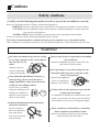
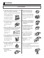
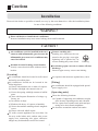
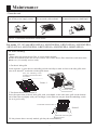
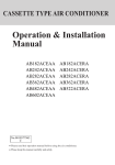
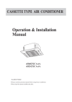
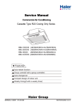
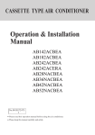
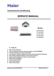
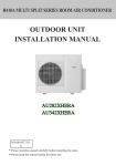
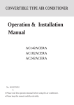
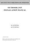
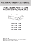
CASSETTE TYPE AIR CONDITIONER Operation & Installation Manual AB122ACEAA AB182ACEAA AB242ACEAA AB242AEEAA AB282ACEAA AB282AEEAA AB362ACEAA AB422AEEAA AB482ACEAA AB482AEEAA AB602ACEAA AB122ACERA AB182ACERA AB242ACERA AB242AEERA AB282AEERA AB362ACERA AB362AEERA AB482AEERA AB602ACERA No.0010577963 F Please read this operation manual before using the air conditioner. Please keep this manual carefully and safely. Contents Cautions ........................................................................................... 1-5 Unit Appearance................................................................................ 6 Maintenance................................................................................... 7-10 Trouble Shooting .......................................................................... 11-12 When Trouble Happens.................................................................. 13-15 Customer Need-to-know...................................................................... 16 Installation Procedure .................................................................... 17-26 Cautions Disposal of the old air conditioner Before disposing an old air conditioner that goes out of use, please make sure it's inoperative and safe. Unplug the air conditioner in order to avoid the risk of child entrapment. It must be noticed that air conditioner system contains refrigerants, which require specialized waste disposal. The valuable materials contained in a air conditioner can be recycled. Contact your local waste disposal center for proper disposal of an old air conditioner and contact your local authority or your dealer if you have any question. Please ensure that the pipework of your air conditioner does not get damaged prior to being picked up by the relevant waste disposal center, and contribute to environmental awareness by insisting on an appropriate, anti-pollution method of disposal. address of the waste materials collecting centers and waste paper disposal services nearest to your house. Safety Instructions and Warnings Before starting the air conditioner, read the information given in the User's Guide carefully. The User's Guide contains very important observations relating to the assembly, operation and maintenance of the air conditioner. The manufacturer does not accept responsibility for any damages that may arise due to non-observation of the following instruction. Damaged air conditioners are not to be put into operation. In case of doubt, consult your supplier. Use of the air conditioner is to be carried out in strict compliance with the relative instructions set forth in the User's Guide. Disposal of the packaging of your new air conditioner Installation shall be done by professional people, don't install unit by yourself. All the packaging materials employed in the package of your new air conditioner may be disposed without any danger to the environment. For the purpose of safety, the air conditioner must be properly grounded in accordance with specifications. The cardboard box may be broken or cut into smaller pieces and given to a waste paper disposal service. The wrapping bag made of polyethylene and the polyethylene foam pads contain no fluorochloric hydrocarbon. Always remember to unplug the air conditioner before opening inlet grill. Never unplug your air conditioner by pulling on the power cord. Always grip plug firmly and pull straight out from the outlet. All electrical repairs must be carried out All these valuable materials may be taken to a by qualified electricians. Inadequate repairs waste collecting center and used again after may result in a major source of danger for adequate recycling. the user of the air conditoiner. Consult your local authorities for the name and 1 Cautions Do not damage any parts of the air conditioner that carry refrigerant by piercing or perforating the air conditioner's tubes with sharp or pointed items, crushing or twisting any tubes, or scraping the coatings off the surfaces. If the refrigerant spurts out and gets into eyes, it may result in serious eye injuries. Do not obstruct or cover the ventilation grille of the air conditioner. Do not put fingers or any other things into the inlet/outlet and swing louver. Do not allow children to play with the air conditioner. In no case should children be allowed to sit on the outdoor unit. Specifications The refrigerating circuit is leak-proof. The machine is adaptive in following situation 1. Applicable ambient temperature range: For EAA series : DB C WB C Cooling outdoor DB C WB C Indoor DB C Heating WB C outdoor DB C WB C Indoor Rated Maximum Minimum 27 32 18 19 23 14 35 43 10 24 26 6 20 27 15 14.5 --7 24 -7 6 18 -- 2. If the supply cord is damaged, it must be replaced by the manufacturer or its service agentor a similar qualified person. 3. If the fuse on PC board is broken please change it with the type of T 3.15A /250VAC. 4. The wiring method should be in line with the local wiring standard. 5. The power and connecting cable are selfprovided, For series 122, AB182ACEAA, The requirement of the power cable: H05RN-F 3G 2.5mm2 . The requirement of connecting cable: H05RN-F 3G 2.0mm2 +H05RN-F 1x0.75mm2. For other series, refer to outdoor operation manual to select the power cable and connecting cable. 6. The breaker of the air conditioner should be all-pole switch; and the distance between its two contacts should be no less 3mm. Such means for disconnection must be incorporation in the fixed wiring. 7. The waste battery shall be disposed properly. 8. The indoor unit installation height is at least 2.5m. 9. The air breaker and the power switch should installed the conveniently reachable pleace for user. 10.For models AB242AEEAA,AB242AEERA, AB282AEEAA,AB282AEERA, the emergency switch on panel is not available. For ERA series: Rated Maximum Minimum 32 18 DB C 27 Indoor 23 14 WB C 19 Cooling DB C 35 43 -5 outdoor WB C 24 26 -27 15 Indoor DB C 20 Heating --WB C 14.5 7 24 -15 DB C outdoor 18 -WB C 6 2 Cautions Safety cautions Carefully read the following information in order to operate the airconditioner correctly. Below are listed three kinds of Safety Cautions and Suggestions. WARNING! Incorrect operations may result in severe consequences of death or serious injuries. CAUTION! Incorrect operations may result in injuries or machine damages; in some cases may cause serious consequences. INSTRUCTIONS: These information can ensure the correct operation of the machine. Be sure to conform with the following important Safety Cautions. The Safety Cautions should be at hand so that they can be checked at any time when needed. If the conditioner is transferred to the new user, this manual should be as well transferred to the new user. WARNING! Don't blow the human body with the cooling air too long, and don't let the room temperature decrease too low either. Please let the dealer be responsible for installing the conditioner. Incorrect installation may cause water leak, electrical shock and fire hazard. Otherwise the one will feel unpleasant or harm ones' health. Don't put fingers or any other things into the inlet/outlet and swing louver while the conditioner is in operation. Because the highspeed fan is very dangerous and may cause injuries. If any abnormal phenomena is found (e. g. smell of firing), please cut off the power supply immediately, and contact the dealer to find out the handling method. In such case, to continue using the conditioner will switch damage the conditioner, off and may cause electrical shock or fire hazard. Call the dealer to take measures to prevent the refrigerant from leaking. If conditioner is installed in a small room be sure to take every measure in order to prevent suffocation accident even in case of refrigerant leakage. When need maintenance and repairment, call dealer to handle it. Incorrect maintenance and repairment may cause water leak, electrical shock and fire hazard. When conditioner is deinstalled or reinstalled dealer should be responsible for them. Incorrect installation may cause water leaking, electrical shock and fire hazard. 3 Cautions CAUTIONS! Don't operate the air-conditioner with damp hands. Otherwise will be shocked. Conditioner should not be used for any other purpose other than airconditioning. Don't use air-conditioner for any other special purposes, e.g. the preservation and protection of food, animals, plants, pecision apparatus as well as work of art, otherwise the qualities of these stuffs may be damaged. Only use correctly-typed fuse. May not use wire or any other materials replacing fuse, otherwise may cause faults or fire accidents. Don't place any burning unit in the air flow of air-conditioner, which may cause incomplete combustion. Don't dismantle the outlet of the outdoor unit. The exposure of fan is very dangerous which may harm human beings. No inflammable spray fluid should be permitted to be placed or used near to airconditioner otherwise may cause fire accidents. When air-conditioner is co-used with other heat-radiator the frequent replacement of room atmosphere should be required. Inefficient ventilation may cause suffocation. Air-conditioner should be cleaned only after power supply is cut off to keep from shock or hurt. After a long time use of air-conditioner the base should be checked for any damages. If the damaged base is not repaired, the unit may fall down and cause accidents. Don't clean air-conditioner with water. Otherwise may cause shock. No goods or nobody is permitted to placed on or stand on outdoor unit. The falling of goods and people may cause accidents. When use the fumigating insecticide don't open air-conditioner. Otherwise the poisonous chemicals may settle in air-conditioner which harm the health of chemical-allergic people. Pets and plants should not be blowed directly in the air flow. Otherwise will suffer damage. 4 Cautions Installation Please ask the dealer or specialist to install, never try by the users themselves. After the installation please be sure of the following conditions. WARNING ! Please call dealer to install the air-conditioner. Incorrect installation may cause water leaking, shock and fire hazard. CAUTION ! Air-conditioner can't be installed in the environment with inflammable gases because the inflammable gases near to air-conditioner may cause fire hazard. Connect earthing wire. Earthing wire should not be connected to the gas pipe, water pipe, lightning rod or phone line, incorrect earthing may cause shock. Installed electrical-leaking circuit breaker. It easily cause electrical shock without circuit breaker. Earthing Use discharge pipe correctly to ensure efficient discharge. Incorrect pipe use may cause water leaking. [Location] Air-conditioner should be located in well-vented and easily-accessible place. Air-conditioner should not be located in the following places: (a) Places with machine oils or other oil vapours. (b) Seaside with high salt content in the air. (c) Near to hot spring with high content of sulfide gases. (d) Area with frequent fluctuation of voltage e.g. factory, etc. (e) In vehicles or ships. (f) Kitchen with heavy oil vapour or humidity. (g) Near to the machine emitting electric-magnetic waves. (h) Places with acid, alkali vapuor. TV, radio, acoustic appliances etc are at least 1 m far away to the indoor unit, outdoor unit, power supply wire, connecting wire, pipes, otherwise images may be disturbed or noises be created. As required, take measures against heavy snow. [Wiring] Air-conditioner should be equipped with special power supply wire. [Operating noise] Chose the following locations: (a) Capable of supporting air-conditioner weight, don't increase operating noise and vibration. (b) Hot vapour from outdoor unit outlet and operating noise don't disturb neighbour. No obstacles around the outdoor unit outlet. 5 Unit Appearance AB122ACEAA - AB122ACERA - AB182ACEAA AB182ACERA AB242ACEAA - AB242ACERA - AB282ACEAA AB282AEERA - AB362ACEAA -AB362AEERA AB422AEEAA - AB482AEEAA - AB482AEERA AB242AEEAA - AB242AEERA - AB282AEEAA AB362ACERA - AB482ACEAA - AB602ACEAA AB602ACERA 6 Maintenance Clean the unit Turn off the power supply switch Do not touch with wet hand. Do not use hot water or volatile liquid ON OFF NOTE: For detailed information consult dealer. For series 122, 182 and AB242AEEAA, AB242AEERA, AB282AEEAA, AB282AEERA, AB362ACEAA, AB362AEERA, AB422AEEAA, AB482AEERA, AB482AEEAA Air filter washing Manual: Please don't tear down the air filter, or it may lead to trouble. If the environment where the air-con works is full of dust, the air filter should be wash more times than ever ( it is usually twice a week). 1.Get the air inlet grille Look at picture 1, press the two embeding switch vertically to make it close to the side grille, then o raise it for about 45 to take the air inlet grille down. Press the embeding switch according to the direction of the arrowhead. Picture 1 Get the air inlet grille. 2. Tear down the air filter (Picture 2) Press the outer brim of the air inlet grille with your thumb, at the same time, pull out the bottom rim of the filter net slightly with your forefinger, so the filter net can part from the embeding switch for us to get it easily. The bottom rim of the filter net Picture 2 The brim of air inlet grille PS: the pictures above are only models, pls obey the real machinery. 7 Maintenance For series 602 and AB242ACEAA, AB242ACERA, AB282ACEAA, AB362ACERA, AB482ACEAA Clean the air filter Instructions : When not for cleaning, do not dismantle the air filter, otherwise it may cause trouble. When the air conditioner is used in a dusty environment, the air filter should be cleaned more often (generally once every two weeks). Open 1. Open air inlet grille Pull the two handles at the same time, slowly draw them out. (when closing it, the procedure is reversed.) 2.Dismantle the air filter Pull the two side handles at the back of the air inlet grille, lift the air filter to dismantle it. 3. Clean Notice Do not use the hot water over 50 C to clean to avoid discoloration or deformation. Do not dry the unit on fire, the filter may be burnt. Use cleaner or water to clean to remove dust. Open and remove (A) Use cleaner to remove dust. (B) When the dust is too much, use soft brush and neutral detergent. (C) Throw the water off, then put it in the shadow for airing. 4. Install air filter (1).Put the air filter into those extruding parts at the top of the air inlet grille. (2).Draw the handles at the back of the air inlet grille inwards to fix the air filter. 5. Close air inlet grille Referring to procedure 1. 8 Maintenance Clean the air inlet grille 1. Open air inlet grille Pull the two handles at the same time, slowly draw them out. (when closing it, the procedure is reversed.) 2. Remove air filter Open Referring to Clean the air filter. 3. Remove the air inlet grille Open the air inlet grille for 45 , the lift it up. 4. Clean Notice Do not use the hot water over 50 C to clean to avoid discoloration or deformation. Use soft brush, water and neutral detergent to clean, then throw the water off. Instruction When there is too much dust Use ventilation fan or directly spray the detergent special for kitchen ware on the air inlet grille, 10 minutes later use water to clean. 5. Install air inlet grille Referring to procedure 3. 6. Install the air filter Referring to Clean the air filter 7. Close air inlet grille Referring to procedure 1. 9 Maintenance Seasonal Reserve Post-season Care Operate the unit with FAN mode on a fair day for about half a day to dry the inside of the unit well. Stop operation and turn off the power supply switch .Electric power is consumed even the air conditioner is in stop. Clean the air filter, indoor unit and outdoor unit,and cover the unit with dustcoat. Pre-season Care See that there is no obstacles blocking the air inlet and air outlet of both indoor and outdoor unit to avoid reduce the working efficiency. Be sure to install the air filter, ensure that the air filter is not dirty. Otherwise may result in machine damages or cause malfunciton due th dust inside the unit To prevent compressor when start in HEAT mode, please cut in the power supply switch 12 hours before starting run,furthermore, always keep the power supply switch on during the using senson. NOTE 1. The inner part of indoor unit must be cleaned. Consult dealer, because clean must be done by technician. 2. In cooling operation, discharging system discharge water in room. 10 Trouble Shooting The followings are not malfuncition When the air conditoner is started, when the compressor starts or stops during operation or when the air conditioner is stopped,it sometimes sounds Bi- Bi- or Godo-Godo. It is the flowing sound of the refrigerant , not a malfunction. Water flowing sound is heard Hua Hua Cracking sound is heard This is caused by heat expansion or contraction of plastics It smells. Air blown out from the indoor unit sometimes smells. The smell results from smells of furniture, paint , tobacco absorbed by indoor unit. During operation, white fog comes out of indoor unit. When in COOL or DRY mode, a thin water fog can be seen blown out of unit ,this is the condensed fog because the suddenly cooled indoor air is blown out. Automatically switch into FAN mode during cooling. To prevent frost from being accumulated on the indoor unit heat exchanger, it sometimes automatically switched into the FAN mode,but it will soon back to the cooling mode. The air conditioner cannot be restarted soon after it stops. Air conditioner does not start? This is because of the self-protection function of the system, therefore,it cannot be restarted for about three minutes after it stops. Please wait for three minutes 11 Trouble Shooting Air does not blow or the fan speed cannot be changed during drying. In DRY mode, when room temperature becomes 2 C higher than temperature setting, unit rill run intermittently at LO speed regardless of FAN setting This happens when the frost accumulated on the outdoor unit is removed (during defrosting operation). Water or vapor generated from the outdoor unit during heating. Defrosting operation During heating,indoor fan is still running even unit is stopped. To get ride of the excess heat, indoor fan will continue running for a while after unit automatically stops. Please check the following things about your air conditioner before making a service call. Unit fails to start. Is the power supply switch on ? Is city supply power normal ? Is the earth leakage breaker in action ? **? ON OFF Power supply switch is not in ON position. Be sure to turn off the power supply switch immediately and contact the sales dealer. 12 When Trouble Happens Insufficient cooling or heating The operation controller adjusted as required Any obstacle exists at the air inlet or outlet? Air filter too dirty ? Horizontal swing louver upward ? (in HEAT mode) Door or window left opened ? Insufficient cooling Any other heat sources in the room? Sunlight direct into the room ? Too crowed in the room ? Cooled air blown out ( when heating) When the air conditioner does not operate properly after you have checked the above-mentioned items or when following phenomenon is observed,stop the operation of the air conditioner and contact your sales dealer. 1)The fuse or breaker often shuts down. 2)Water drops off during cooling or drying operation. 3)There is an irregularity in operation or abnormal sound that is audible. 13 14 72(48H) 83(53H) 71(47H) 07(07H) 06(06H) 08(08H) 11(0BH) 03(03H) 13(0DH) 76(4CH) 05(05H) 84(54H) 80(50H) 12(0CH) 75(4BH) 77(4DH) 20(32D) 5 6 7 8 9 10 11 12 13 14 15 16 17 18 19 20 21 23D 18D 15D 07D 05D 21D 30D 20D 31D 15D 17D 26D 15D 10D 14D 22D 06D 01D 02D 11D 12D Communication abnormal for more than 4m continuously Communication abnormal for more than 4m continuously Float switch broken down for more than 25m continuously Outside signal broken down for more than 10s Sensor broken down or short circuit for more than 2m continuously Solenoid valve act incorrectly 3 times continuously Sensor broken down or short circuit for more than 2m continuously EEPROM data missing Low pressure switch acts in normal running The discharging temperature is higher than 120degree CT check abnormal 3 times in 30m High pressure switch acts 3 times in 30m Fault phase, short of phase, out of balance greatly Sensor broken down or short circuit for more than 2m continuously Sensor broken down or short circuit for more than 2m continuously Sensor broken down or short circuit for more than 2m continuously Sensor broken down or short circuit for more than 2m continuously Reason Abnormal mode Indoor operation mode is different with the running indoor unit. Outdoor coil B(suction temp sensor-for MRV II) Sensor broken down or short circuit for more than 2m continuously Outdoor discharging B(oil temp sensor-for MRV II) Sensor broken down or short circuit for more than 2m continuously Spdu module temperature is too high SPDU module temperature protection Over-current protection High pressure abnormal Power supply abnormal Communication between wired controller and indoor abnormal Communication between indoor and outdoor abnormal Drainage system abnormal Outside alarm signal input Gas pipe temp. sensor abnormal Temperature protection malfunction Discharging temp. sensor abnormal EEPROM abnormal Pressure abnormal(low pressure) Compressor overheat Indoor ambient temp. sensor failure Indoor coil temp. sensor failure Outdoor ambient temp. sensor failure Outdoor coil temp. sensor failure shows resumable fault, shows it is not resumable fault. 01(01H) 02(02H) 74(4AH) 73(49H) Failure code For central Failure description control, on wired failure code controller For remote type, flash times 1 2 3 4 Resumable if lower than 100 degree Remarks When Trouble Happens Error display ( For ERA series ) 15 83(53H) 07(07H) 06(06H) 08(08H) 11(0BH) 03(03H) 13(0DH) 05(05H) 80(50H) 12(0CH) 75(4BH) 77(4DH) 6 8 9 10 11 12 13 15 17 18 19 20 shows resumable fault, 23D 18D 15D 05D 21D 30D 20D 31D 17D 15D 06D Communication abnormal for more than 4m continuously Float switch broken down for more than 25m continuously Outside signal broken down for more than 10s Sensor broken down or short circuit for more than 2m continuously Solenoid valve act incorrectly 3 times continuously EEPROM data missing The discharging temperature is higher than 120degree Abnormal mode Indoor operation mode is different with the running indoor unit. Outdoor coil B(suction temp sensor-for MRV II) Sensor broken down or short circuit for more than 2m continuously Outdoor discharging B(oil temp sensor-for MRV II) Sensor broken down or short circuit for more than 2m continuously Communication between wired controller and indoor abnormal Communication between indoor and outdoor abnormal Drainage system abnormal Outside alarm signal input Gas pipe temp. sensor abnormal Temperature protection malfunction EEPROM abnormal Compressor overheat Sensor broken down or short circuit for more than 2m continuously Sensor broken down or short circuit for more than 2m continuously Sensor broken down or short circuit for more than 2m continuously Sensor broken down or short circuit for more than 2m continuously Indoor ambient temp. sensor failure Indoor coil temp. sensor failure Outdoor ambient temp. sensor failure Outdoor coil temp. sensor failure/Compressor discharging temp. sensor abnormal Over-current protection / Power supply abnormal High/Low pressure abnormal CT check abnormal 3 times in 30m / Fault phase, short of phase, out of balance greatly High pressure switch acts 3 times in 30m/Low pressure switch acts in normal running Communication abnormal for more than 4m continuously Reason Failure description shows it is not resumable fault. 10D 72(48H) 5 14D For central control, failure code 01D 02D 11D 12D For remote Failure code type, flash on wired times controller 1 01(01H) 2 02(02H) 3 74(4AH) 4 73(49H) Resumable if lower than 100 degree Remarks When Trouble Happens Error display ( For EAA series ) Customer Need-to-know Customer Need-to-know Please install the air conditioner according to the requirements specified in this manual to ensure the air conditioner work well. Be careful not to scratch the surface of the case during moving the air conditioner. Please keep the installation manual for future reference when maintenance and changing installation place. After installation ,please use the air conditioner according to the specification in the operation manual. Using Directions Avoid direct sunlight and airflow Adjust suitable airflow direction Keep the proper indoor temperature. Too cool or hot is not good for your health. Furthermore,it will result in excessive consumption of electric power. Effectively use timer. Using TIMER mode, you can make the room temperature reach a suitable temperature when you wake up or back home. Optimal temperature 16 Installation Procedure CAUTIONS: To ensure proper installation, read "Cautions" carefully before working. After installation, start the unit correctly and show customers how to operate and maintain the unit. Meanings of Warning and Cautions: Warning! Serious injury or even death might happen, if it is not observed. Caution! Injury to people of damages to machine might happen, if it is not observed. WARNING! Installation shall be done by professional people, don't install unit by yourself. Incorrect installation will cause water leakage, electric shock or fire. Install unit as per the Manual. Incorrect installation will cause water leakage, electric shock or fire accident. Be sure to use specified accessaries and parts. Otherwise, water leakage, electric shock, fire accident or unit falling down may happen. Unit should be placed on a place strong enough to hold the unit. Or, unit will fall down causing injuries. When install the unit, take in consideration of storms, typhoom, earthquake. Incorrect installation may cause unit to fall down. All electric work shall be done by experienced people as per eocal code, regulations and this Manual. Use exclusive wire for the unit. Incorrect installation or undersized electric wire may cause electric shock or fire accident. All the wires and circuit shall be safe. Use exclusive wire firmly fixed. Be sure that external force will not affect terminal bolck and electric wire. Poor contact and installation may cause fire accident. Arrange wire correctly when connectin indoor and outdoor power supply. Fix terminal cover firmly to avoid overheat, electric shock or even fire accident. In case retrigerant leakage occurred during unit installation, keep a good ventilation in the room. Poisonous gas will occur when meet with fire. Check the unit upon installation. Be sure there is no leakage. Refrigerant will induce poisonous gas when meet heat source as heater, oven, etc. Cut power supply before touching terminal bolck. CAUTION! Unit shall be grounded. But grounding shall not be connected to gas pipe water pipe, telephone line. Poor grounding will cause electric shock. Be sure to install a leakage breaker to avoid electric shock. Earthing Arrange water drainage according to this Manual. Cover pipe with insulation materials in case dew may occur. Unproper installation of water drainage will cause water leakage and wer your furniture. To maintain good picture or reduce noise, keep at least 1 m from T.V. radio, when install indoor and ou tdoor unit, connecting wire and power line. (If the radio wave is relatively strong, 1 m is not enough to reduce noise). Don't install unit in following places: (a) Oil mist or oil gas exists, such as kitchen, or, plastic parts may got aged, or water leakage. (b) Where there is corrosive gas. Copper tube and welded part may be damaged due to corrosion, causing leakage. (c) Where there is strong radiation. This will affect unit's control system, causing malfunction of the unit (d) Where flamable gas, dirt, and volatile matter (thinner, gasoline) exist, These matter might cause fire accident. Refer to paper pattern when installing unit. Cautions for the installation personnel Don't fail to show customers how to operate unit. 17 Installation Procedure 1 BEFORE INSTALLATION 1. <Don't discard any accessories until comp> Determine the way to carry unit to installation place. Don't remove packing until unit reaches installation place. If unpacking is unkavoidable, protect unit properly. 2 SELECTION OF INSTALLATION PLACE 2. Air outlet 1500 Over 2500 Over H (1) Installation place shall meet the following and agreed by customers: Place where proper air flow can be ensured. No block to air flow. Water drainage is smpoth. Place strong enough to support unit weight. Place where inclination is not evident on ceiling. Enough space for mainenance. Indoor and outdoor unit piping length is within limit. (Refer to Installation Manual for outdoor unit.) Indoor and outdoor unit, power cable, inter unit cable are at least 1 m away fromT.V. radop. This is helpful to avoid picture disturbance and noise. (Even if 1 m iskept, noise can still appear if radio wave is strong) (2) Ceiling height Indoor unit can be installed on ceiling of 2.5-3m in height. (Refer to Foeld setting and Installation Manual of ornament panel.) (3) Install suspending bolt. Check if the installation place is strong enough to hold weight. Take necessary measures in case it is not safe. (Distance between holes are marked on paper pattern. Refer to paper pattern for place need be reinforced) Installation space Model H Air inlet Air outlet 1500 Over Series 122, 182 AB282AEERA,AB362ACEAA,AB362AEERA, AB362ACERA,AB422AEEAA,AB482ACEAA, AB482AEERA,AB482AEEAA,AB602ACERA 310 Series 242 AB282ACEAA,AB282AEEAA 280 3 PREPARATION FOR THE INSTALLATION 3. (1) Position of ceiling opening between unit and suspending bolt. 1280(Ceiling opening) 1070 (Distance between suspending bolts) 515 Suspending bolts 780(Distance between suspending bolts) 840(Indoor unit) Distance between suspending bolts 535mm Indoor unit 570mm Ceiling opening 650mm Ornament panel 700mm 515 950(Ornament panel) Suspending bracket Suspending bolts Note: Dimension of ceiling opening marked with * can be as large as 910mm, but the matching part of ceiling with ornament panel shall be over 20mm. Ceiling Ornament panel 60 320mm Ceiling 20 Over 60mm 150mm 140 Overlap between ceiling and ornament panel shall be 25mm 890(Ceiling opening) 860(Ceiling opening) Refrigerant pipe For series 602 and AB362ACERA, AB482ACEAA 780 (Distance between suspending bolts) 780 (Distance between suspending bolts) 840(Indoor unit) 890(Ceiling opening) 950(Ornament panel) Ornament panel 700mm series 242 and AB282ACEAA, AB282AEEAA Indoor unit 570mm Ceiling opening 650mm series 122,182 18 Installation Procedure AB282AEERA, AB362ACEAA, AB362AEERA, AB422AEEAA, AB482AEERA, AB482AEEAA 50 0 860-890(ceiling hole) 950 ov er 1 690 (Hanging position) Wall or barrier ov 790 ov er 15 00 er 15 00 35 150 134 35 below 3000 over 1000 60 164 149 88 85 149 287 00 ov 35 950 840 346 35 840 346 860-890 er 15 Barrier Ground (2) Cut an opening in ceiling for installation if necessary. (when ceiling already exists.) Refer to paper pattern for dimension of ceiling hole. Connect all pipings (refrigerant, water drainage), wirings (inter unit cable) to indoor unit, before installation. Cut a hole in ceiling, may be a frame should be used to ensure a smooth surface and to prevent vibration. Contact your real estate dealer (3) Install a suspending bolt. (Use a M10 bolt) To support the unit weight, anchor bolt shall be used in the case of already exists ceiling. For new ceiling, use built-in type bolt or parts prepared in the field. Before going on installing adjust space between ceiling. 50~100 <Installation example> Roof Anchor bolt Long nut Suspending bolt Ceiling Note: All the above mentioned parts shall be prepared in field. 19 Installation Procedure 4 INSTALLATION OF INDOOR UNIT 4. In the case of new ceiling (1) Install unit temporally Put suspending bracket on the suspending bolt. Be sure to use nut and washer at both ends of the bracket. (2) As for the dimensions of ceiling hole, see paper pattern. Ask your real estate dealer for details. Center of the hole is marked on the paper pattern. Center of the unit is marked on the card in the unit and on the paper pattern. Mount paper pattern 5 onto unit using 3 screws 6 . Fix the corner of the drain pan at piping outlet. < After installation on the ceiling > (3) Adjust unit to its right position. (Refer to preparation for the installation-(1)) (4) Check unit's horizontal level. Watert pump and flating switch is installed inside indoor unit, check four corners of the unit for its level using horizontal compartor or PVC tube with water. (If unit is tilting against the direction of water drainage, problem may occur on floating switch, causing water leakage.) (5) Remove the washer mounlting 2 , and tighten the nut above. (6) Remove the paper pattern. Nut (Prepare in feild) Washer (Prepared in feild) In the case of ceiling already exists (1) Install unit temporally Put suspending bracket on the suspending bolt. Be sure to use nut and washer at both ends of the bracket. Fix the bracket firmly. (2) Adjust the height and position of the unit. (Refer to preparation for the installation (1) ). (3) Proceed with 3 and 4 of "In the case of new ceiling". Suspending bolts Fasten (double nuts) Insert Washer fixing pad (prepared in feild) [ secure the washer firmly] Level Polythene pipe Screws at the piping outlet is fixed at the corner of drain pan. Center of ceiling hole Paper pattern Screw (accessory) [Fix the paper pattern] 20 Paper pattern 5 Screw (accessory) Installation Procedure 5 REFRIGERANT PIPING (As for outdoor piping, please refer to installation Manual of outdoor unit.) 5. Outdoor is precharged with refrigerant. Be sure to see the Fig.1, when connecting and removing piping from unit. For the size of the flare nut, please refer to Table 1. Apply refrigerant oil at both inside and outsid of lflare nut. Tighten it band tight 3-4 turns then tighten it. Use torque specified in Table 1. (Too much force may damage flare nut, causing gas leakage). Check piping joints for gas leakage. Insulate piping as shown in Fig. below. Cover joint of gas piping and insulator 7 with seal. Table 1 Pipe size Medium size seal pad 11 (accessory) (Cover the piping joint with seal pad.) Torque spanner 9.52 3270~3990N.cm 12.0~12.4 (333~407kgf.cm) spanner Gas pipe Liquid pipe Flare nut Flare shape A(mm) 6.35 1420~1720N.cm 8.3~8.7 (144~176kgf.cm) Clamp 3 Piping joing Tighten torque Insulator (accessory) (For liquid pipe) 8 Insulator (accessory) (For gas pipe) 7 15.88 6180~7540N.cm 18.6~19.0 (630~770kgf.cm) 19.05 9720~11860N.cm 22.9~23.3 (990~1210kgf.cm) 90 0.5 45 2 A Apple refrigerant oil R0.4 ~ 0.8 6 INSTALLATION OF WATER DRAINAGE PIPE 6. (1) Install water drainage pipe Pipe dia, shall be equal or larger than that of unit piping.(pipe of polyethylent; size: 25mm; O.D:32mm) Drain pipe should be short, with a downward slope at least 1/100 to prevent air bag from happening. If downward slope can't be made, take other measures to lift it up. Keep a distance of 1-1.5m between suspending brackets, to make water hose straight. 1-1.5m Slope over 1/100 Use the self-provided stiff pipe and clamp 1 with unit. Insert water pipe into water plug until it reaches the white tape. Tighten the clip until head of the screw is less than 4mm from hose. Wind the drain hose to the clip using seal pad 9 . Large size seal pad 10 Insulate drain hose in the room. (accessory) Clamp Clamp (accessory) Tape (White) Self-provided stiff pipe <Cautions for the drain water lifting pipe> Installation height shall be less than 280mm. There should be a right angle with unit, 300mm from unit. 500 below drain water lifting pipe Self-provided stiff pipe (accessory) 75 below Suspending bracket 500 below 1~1.5m 220 280 below 300mm below Drain hose (accessory) 4mm below Clamp (accessory) (Note) Over 100 The slope of water drain hose (1) shall be within 75mm, don't apply too much force on it. If several water hoses join together, do as per following proceedures. Connect water hoses with a T joint. Specifieations of the water hoses shall meet the requirements for the unit running. (2) Check if water drainage is smooth after installation. 21 Installation Procedure For series 122,182 and AB242AEEAA, AB242AEERA, AB282AEEAA, AB282AEERA, AB362AEERA, AB362ACEAA, AB422AEEAA, AB482AEEAA Check whether indoor unit is horizontal with leveler or polythene pipe filled with water , and check that the dimension of the ceiling opening is correct. Take off the lever gauge before install the ornament panel. Fasten the screws to make the height difference between the two sides of indoor unit less than 5mm. First fix it with screws temporally. Fasten the two temporally fixing screws and other two, and tighten the four screws. Connect the wires of synchro-motor. Connect the wire of signal. If no response of remote controller, check whether the wiring is correct, restart remote controller 10 seconds after shut off power supply. Electric control box <Limits of panel board installation> Install the panel board in the direction shown in the figure. The incorrect direction will result in water leakage, meanwhile swing and signal receiving are displayed that cannot be connected. AB122ACEAA, AB122ACERA, AB182ACEAA POWER SUPPLY: 1PH,220-230V~,50Hz INDOOR UNIT TERMINAL BLOCK OUTDOOR UNIT TERMINAL BLOCK 1 2 3 Y/G 1 2 3 Y/G L N 22 Installation Procedure For series AB242ACEAA, AB242ACERA, AB282ACEAA, AB482ACEAA, AB482AEERA, AB602ACEAA, AB602ACERA Charge, through air outlet or inspecting hole, 1200ccd water to see water drainage. After wiring Check water drainage in cooling operation. When wiring is not complete Remove cover of control box, connect 1PH power to terminal 1 and 2 on terminal block.,use remote controller to operate the unit. Note, in this operation, fan will be running. Upon confirmation of a smooth water drainage, be sure to cut off power supply. Method of water charging 3 Connect with outdoor unit 2 D Water drainage port for maintenance 1 Maintenance Self-provided stiff pipe Inspecting hole Terminal block (Drain water from this hole) PCB on indoor unit Terminal block Charge water from inspecting hole 100mm Watering can of plastic pipe should be about 100 mm long Charge water from air outlet Cover of controll box For series 242, 282, 362,AB182ACERA) INDOOR UNIT TERMINAL BLOCK OUTDOOR UNIT TERMINAL BLOCK LN 1 2 3 For series 422, 482, 602 INDOOR UNIT TERMINAL BLOCK Y/G 1 2 3 OUTDOOR UNIT TERMINAL BLOCK 1 2 3 Y/G R S T N 1 2 3 Y/G Y/G POWER SUPPLY: 1PH,220-230V~,50Hz POWER SUPPLY: 380-400V,3N~,50Hz 23 Installation Procedure 7. 7 WIRING All supplied parts. materials and wiring operation must in appliance with local code and regulations. Use copper wire only. When make wiring, please refer to wiring diagram also. All wiring work must be done by qualified electricians. A circuit breaker must be installed, which can cut power supply to all system. See Installation Manual of outdoor unit for specifications of wires, circuit breaker, switches and wiring etc. Connecting of unit Remove cover of switch box (1) , drag wires into rubber tube A, then, after proper wiring with other wires, tighten clamp A. Connect wires of correct pole to the terminal block inside. Wind seal 12 around wires. (Be sure to do that, or, dew may occur). Upon connecting, replace control box cover (1) and (2). Terminal block Cover of control box(2) * Grounding lead Rubber tube A Cover of control box(1) Don't fail to seal it, or water may come in. Rubber tube Note: Have it sealed, leaving no space. Seal pad (small size 12 ) (Wind around wire) In Out <<WARNING>> Attach seal pad Field wiring Connect wires of the Obscrve the following when connecting power supply same specifications at two sides. terminal block: Don't connect wires of different specifications to the same terminal block. (Loose wire may cause overheating of circuit) Connect wires of same specifications as shown in right Fig. Don't connect wires of the same specifications at one side. Don't connect wires of the different specifications. 8 WIRING EXAMPLE 8. As for outdoor unit circuit, please see Installation Manual of outdoor unit. Note: All electric wires have their own poles, poles must match that on terminal block. 9 INSTALLATION OF ORNAMENT PANEL 9. Bar Cautions for the installation Fig. 1 Be sure to show customers Operation Manual and guide them how to operate unit correctly. Before installation. read also the Installation Manual of indoor unit. With this ornament , 2 or 3 air flow direction is not available. Suitable height is 3 m. Accessory Pad Pad 1. Prepare ornament panel Handling of ornament panel Ornament panel shall not be placed face down or against wall, neither on an uneven object. Don' t bend carelessly the swing flap, or, problem may occur. (1) Remove air inlet grill from ornament panel * 1 Push in the bar on inlet grill and lift it up. (Refer to Fig. 1) 2 Lift it up for about 45 degree and remove it from ornament. Tear off adhesive tape fixing air filter on the back of the air inlet grill. (Refer to Fig. 2) (2) Remove cover plate at corner Tear off the adhesive tape, and slide it off. (Refer to Fig. 3) 24 Adbesive tape 45 Fig. 2 Slide Fig. 3 Installation Procedure 2. Mounting on high ceiling (1) Ornament panel can be mounted on ceiling as high as 3 m. (2) Please install pad as accessary. 1 Cut open the pad along cutting ling. Use part a only and discard part b . (Refer to Fig. 4) 2 Install part a of the pad on the place shown in Fig. 5. Refer to Fig. 6. Cutting line Leave no space. Place it on the frame. a 50 100 b Part a of the pad Fig. 4 Fig. 6 Part a of the pad Side of ornament panel Swing flap motor (3)Wiring on ornament panel Connecting of wiring of the swing flap motor on ornament panel. (2 places) (Refer to Fit . 10) Fig. 5 If connecting is not made, error code (A7) appears on remote controller. So, make proper connecting. Fig. 10 Side of indoor unit Wiring diagram 3. Install ornament panel on indoor unit. For indoor unit installation, please refer to Installation Manual. (1) As shown in Fig.7,match the position of swing flap motor with that of the indoor unit piping hole , so that ormament panel can be placed on to indoor unit. (2) Installation of ornament panel 1 Place the holding ring on swing flao motor side teporarily on hooks of the indoor unit. (2 pcs) 2 Put the other two holding rings on the hooks at both side of the indoor unit. (Care should be taken not to push wiring of swing flap motor into seals). 3 Screw in all 4 screws under holding ring for about 15mm. (Pancl will rise). 4 Adjust the ornament panel as per Fig. 7 to cover opening on the ceiling. 5 Tighten screws to redrce the thickness of seals between ornament and indoor unit to 5-8mm. If screws are not tighten tight, problems in Fig, 8 might occur. Tighten screws properly. Gas leakage. Gas leakage from roof. Contamination Mist exists and drop down. Fig. 8 Holding ring 2 Piping hole position 2 Swing flap motor 3 4 Fig. 7 Indoor unit Ceiling material Seal 5 _ 8mm Ornament panel Caution If there are still space after tightening of screws, please readjust the height of indoor unit. (Refer to Fig. 9) Leave no space. Hook 1 Fig. 9 25 If indoor unit is at horizontal level and water drainage is smooth, then, indoor unit height can be adjusted throrgh holes at corners of ornament panel. Installation Procedure 4. Installation of inlet grill and cover plate (1) Installation of inlet grill Install in reversed order of "Prepare ornament pandl". Inlet grill can be adjusted into four directions by turning inlet grill. Inlet grill position can be adjusted as per customers request. When installing inlet grill, take care not to twist wiring of swing flap motor. (2) Install cover plate on the corner 1 As shown in Fig. 11 tie the 2 cover plate onto the bolt on ornament plate. Install cover plate onto ornament plate. (Refer to Fig. 12) Slide all five hold rings to let them drop in holes Fig. 11 on ornament plate, Fig. 12 Pay special care to the following and check after installation Item to the checked Unproper installation may cause Is indoor unit firmly installed? Unit might fall down, make vibration or noise. Is gas leakage check performed? This may lead to gas shortage. Is unit properly insulated? Dew or water drop may occur. Is water drainage smooth? Dew or water drop may occur. Is power voltage meet that stipulated on the nameplate? Problem may occur or parts got burned. Is wiring and piping correctly arranged? Problem may occur or parts got burned. Is unit safely grounded? There might be a danger of electric shock. Is wire size correct? Problem may occur or parts got burned. Are there any obstacles on air inlet and outlet grill of indoor and outdoor unit? This may cause poor cooling. Is record made for piping length and refrigerant charging amount? It is hard to control refrigerant charging amount. Check ATTENTION: after finishing installation,confirm no refrigerant leakage. 26 HAIER GROUP Qingdao Haier Air Conditioner Electric Co., Ltd. Address: Haier Garden ,Qianwangang Road , Economic Development Zone, Qingdao ,Shandong 266500, P.R.China Web Site: http://www.haier.com